Loading ...
Loading ...
Loading ...
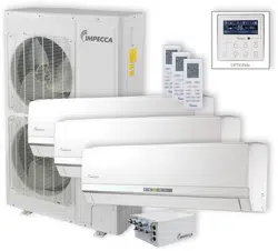
BU Module
21
line to the N(1), 2 terminals with the sign of BU module.
7) Connect the power cable of the indoor unit to the N(1), 2 and 3 terminals with the sign of
Indoor unit A (B, C, D and E) and as well as the ground screw.
8) Fix the power cable and transmission line firmly by cable fixing clip.
9) Screw the electrical equipment plate.
CAUTION
1) The transmission line and the power cable must be separated with an interval of at least 2cm (3/4inch);
otherwise it may be result in communication problem.
2) Confirm the each cable connected to the terminal screw is exactly and securely after finishing the
electric work.
3) Fix each ground wire separately with the ground screw.
4) When connecting indoor units, make sure to connect refrigerant pipes and power cables to the same
connection ports marked with matching signs (A, B, C ,D and E).
5) If the connecting wire is connected to the terminal incorrectly, the unit will not work normally.
6) The refrigerant pipe should be supported by brackets, that is, don’t let the unit withstand the weight of
it.
7) For the Flex+ system, each pipe should be labeled to tell which system it belongs to avoid
mistaken inaccurate piping.
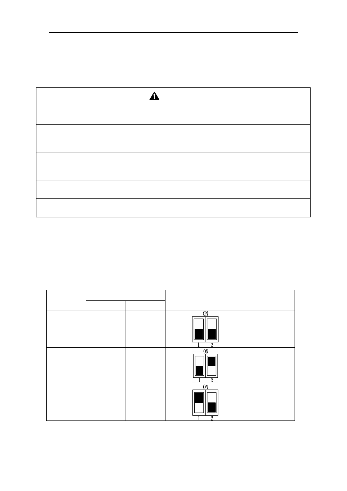
6.7 Instructions for DIP Switch
2 digits DIP is adopted to assign the address when using multi-BU modules and the address
cannot be repeated in the same unit.
One outdoor unit can connect to no more than 3 BU modules.
“ON” side means "ON" and the opposite side represents "OFF".
NOTICE!: The black part is lever.
Table 12
Number
DIP Code
Icon Address
DIP 1 DIP 2
1 OFF OFF BU 1
2 OFF ON
BU 2
3 ON OFF BU 3
Loading ...
Loading ...
Loading ...