Loading ...
Loading ...
Loading ...
page 7
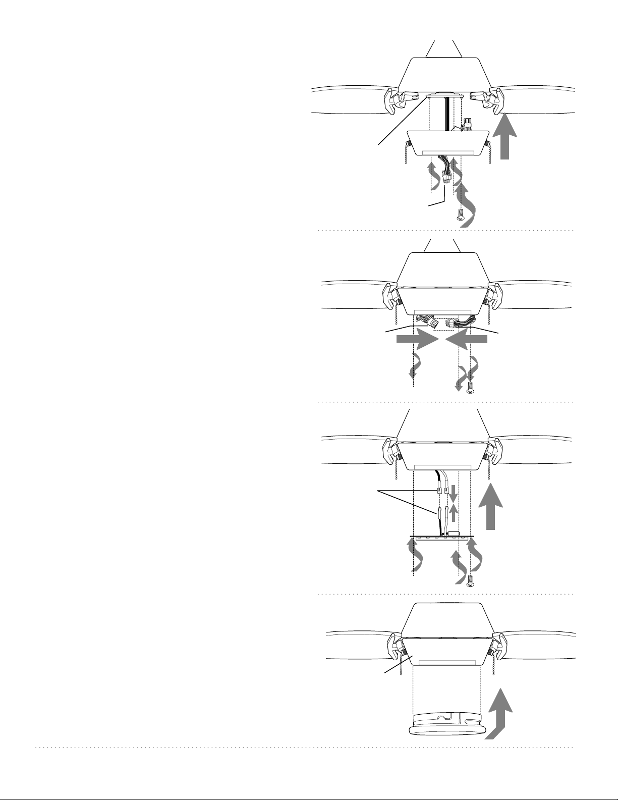
9. Light Kit Assembly.
Remove 1 screw from motor plate on
underside of motor housing and partially
loosen the other 2 screws. Align slotted
holes in center of switch housing with
loosened screws in motor plate, allowing
male plug from motor housing to come
through hole in middle of switch housing.
Twist switch housing to lock. Re-insert
screw that was just removed and securely
tighten all 3 screws with a Phillips
screwdriver. [Refer to diagram 1.]
Remove 3 screws on next level of the
underside of the switch housing.
Connect male plug from motor housing to
female plug from switch housing, matching
up the colors on the male plug with the
colors on the female plug for correct fit. Be
sure that plugs connect securely. [Refer to
diagram 2.]
Connect WHITE wire from LED light plate to
WHITE wire from switch housing. Connect
BLACK wire from LED light plate to BLACK
(or BLUE) wire from switch housing. Be sure
molex connections snap together securely.
[Refer to diagram 3.]
Carefully arrange wiring within switch
housing. Align holes in switch housing with
holes in LED light plate. Re-insert screws
that were previously removed and tighten
all 3 screws securely. [Refer to diagram 3.]
To attach glass shade, align grooves on
glass shade with nodules on inside of
switch housing and push up gently on glass
shade. Then, turn glass shade to the RIGHT
(clockwise) until it no longer turns. [Refer to
diagram 4.]
motor plate
male plug
motor
housing
glass shade
switch housing
female
plug
male
plug
LED light plate
diagram 1
diagram 4
molex
connections
diagram 2
diagram 3
motor
housing
motor
housing
switch
housing
Loading ...
Loading ...