SKU NUMBER: 351-8738
MODEL NUMBER: MND5770A
Questions, problems, missing parts?
Before returning to your retailer, call our customer service at 1-800-645-3184,
Monday - Friday, 7: 0 a.m. - 4:00 p.m., CST.0
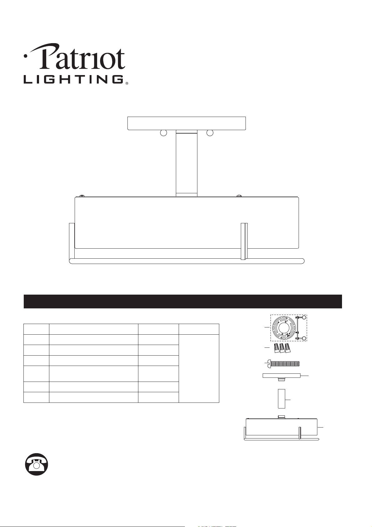
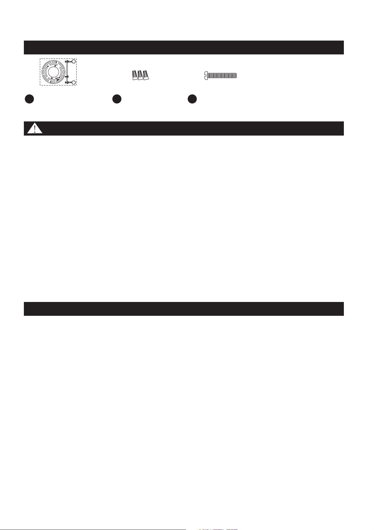
PACKAGE CONTENTS
1
REVISED 2021-04-26
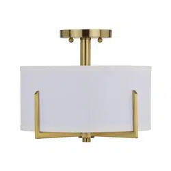
LED SEMI FLUSH MOUNT
PART
DESCRIPTION
QUANTITY
A
1 pc
A
BB
CC
AA
B
B
Stock Part#
AA
BB
CC
Crossbar Assembly
(Pre-assembled to Ceiling Canopy)
Wire Connector
Outlet Box Screw
1 pc
3 pcs
2 pcs
Socket Assembly
1 pc
Ceiling Canopy
C
1pc
Center Column
N/A
C
2
SAFETY INFORMATION
Please read and understand this entire manual before attempting to assemble, operate or install the
product.
WARNING:
● Turn off electricity at main fuse box (or circuit breaker box) before beginning installation by removing
fuse (or switching off circuit breaker).
● Be careful not to damage or cut the wire insulation (covering) during fixture installation. Do not permit
wires to contact any surface having a sharp edge. To do so may damage or cut the wire insulation,
which could cause serious injury or death from electric shock
CAUTION:
● All electrical connections must be in agreement with local codes, ordinances or the national electric
code (NEC). Contact your municipal building department to learn about your local codes, permits
and/or inspections.
● Risk of fire – most dwellings built before 1985 have supply wire rated for 140°F/60ºC. Consult a
qualified electrician before installation.
● Do not connect this fixture to an electrical system that does not provide a means for equipment
grounding. Never use a fixture in a two-wire system that is not grounded. If you are not sure your
lighting system has a grounding means, do not attempt to install this fixture. Contact a qualified,
licensed electrician for information with regards to proper grounding methods as required by the local
electrical code in your area.
● If a dimmer control switch is used with this fixture, obtain professional advice to determine the correct
type and electrical rating required.
Before beginning assembly, installation or operation of product, make sure all parts are present. Compare
parts with package contents list and diagram on previous page. If any part is missing or damaged, do not
attempt to assemble, install or operate the product. Contact customer service for replacement parts
Bulb Recommended: LED-30W
Tools equired for ssembly (not included): Screwdriver, Phillips Screwdriver, Pliers, Electrical Tape,ra
Safety Glasses, Ladder.
PREPARATION
HARDWARE CONTENTS Note: Hardware is not shown to actual size.
Crossbar Assembly
x 1
Wire Connector
x 3
Outlet Box Screw
x 2
AA BB CC
ASSEMBLY INSTRUCTIONS
3
Outlet Box
STEP :2
a. Secure the crossbar assembly (AA) to the outlet
box (not included) with the outlet box screws (CC).
b. Tighten until snug.
Note:
The preassembled mounting screws on the
crossbar assembly (AA) should protrude outward.
AA
CC
STEP :3
a. Fit the ceiling canopy (A) to the crossbar assembly
(AA) and secure with the mounting balls.
Note: The ceiling canopy should be snug against
the ceiling and the mounting balls.
If this does not work, adjust the length of the
mounting screws on the crossbar assembly (AA)
by unscrewing the preassembled hex nuts.
Then, screw the mounting screws in or out of the
crossbar until the desired length is achieved.
Once the ceiling canopy (A) is secure, remove the
mounting balls and ceiling canopy (A) and proceed
to Step .4
Mounting
Screw
Mounting Ball
Hex Nut
AA
A
B
C
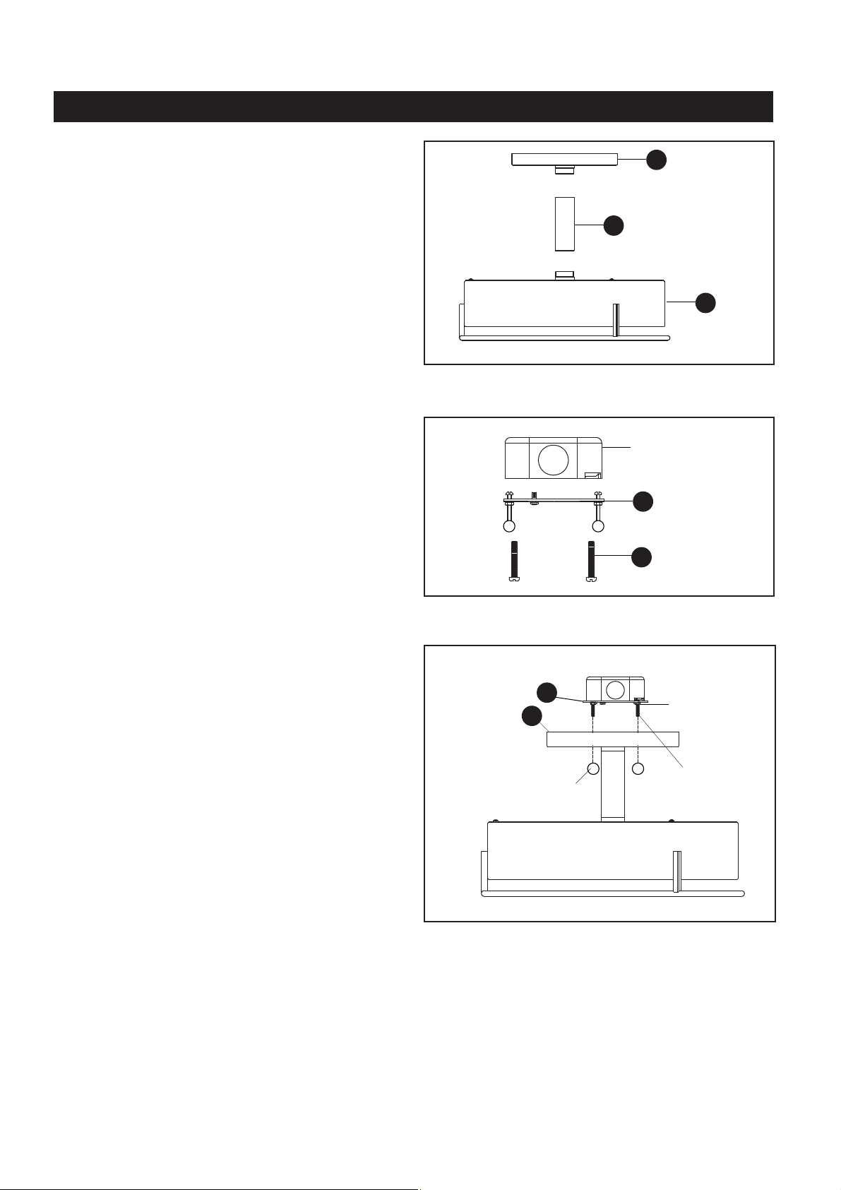
STEP 1:
a. Remove the mounting balls and the crossbar
assembly (AA) from the ceiling canopy (A). Refer
to the diagram in .Step 3
b Pass the supply wires and the ground wires.
through the ceiling canopy (A) and the center
column (B).
c. Thread the ceiling canopy (A), the center column
(B) and the socket assembly (C) together as
shown. Hand-tighten until snug.
A
STEP 1
STEP 2
STEP 3
ASSEMBLY INSTRUCTIONS
4
STEP :5
a. Re-attach the ceiling canopy (A) to the crossbar
assembly (AA).
b. Secure with the previously removed mounting
balls.
Mounting Ball
AA
A
Your installation is now complete! Restore electricity and save this sheet for future reference.
WHITE WIRE
BLACK (OR RED) WIRE
BLACK WIRE
FROM SUPPLY
FROM SUPPLY
FROM FIXTURE
FROM FIXTURE
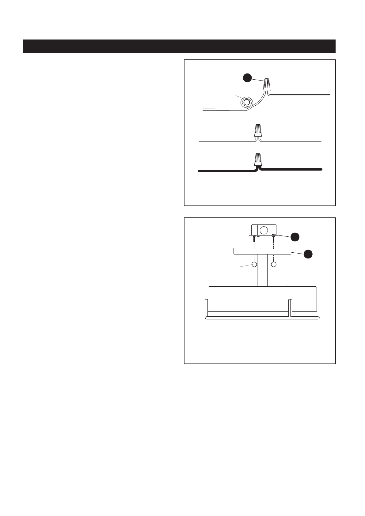
STEP :4
* Use the ire onnectors ( ) to connect thewc BB
wires.
a) Ground Wire:
1. Wrap the supply around theground wire green
ground screw on the mounting bracket, no less
than 2 inches from the end of the wire. Tighten the
ground screw.
2. Connect the fixture to theground wire supply
ground wire with a wire connector (BB).
b) Supply Wire:
1. Connect the to thesupply white wire white
fixture supply wire with a wire connector (BB).
2. Connect the wire to thesupply black (or red)
black fixture supply wire with a wire connector
(BB).
3. Wrap each connection with approved electrical
tape and carefully insert all of the connected
wires into the outlet box.
GROUND WIRE
GROUND WIRE
FROM SUPPLY
FROM FIXTURE
GREEN GROUND SCREW
WHITE WIRE
BB
STEP 4
STEP 5
CARE AND MAINTENANCE
TROUBLESHOOTING
• To clean, turn off and wipe with a damp, non-abrasive cloth.
Questions, problems, missing parts?
Before returning to your retailer, call our customer service at 1-800-645-3184,
Monday - Friday, 7: 0 a.m. - 4:00 p.m., CST.0
5
1) The lights will not turn on:
a) Make sure the wall switch and circuit breaker are on.
b) Make sure the wiring is correct.
2) Fuse blows or circuit trips when light is turned on.
a) Check for crossed wires, ensure wiring is correct.
If unable to fix any of the above issues, please consult a certified electrician.