SEARS
OWNER'S
MANUAL
MODELNO.
390.2519
390.2522
CAUTION:
Read and Fallow
All Safety Rulesand
Operating Instructions
BeforeFirstUseof
ThisProduct.
Save ThisManual For
FutureReference.
@
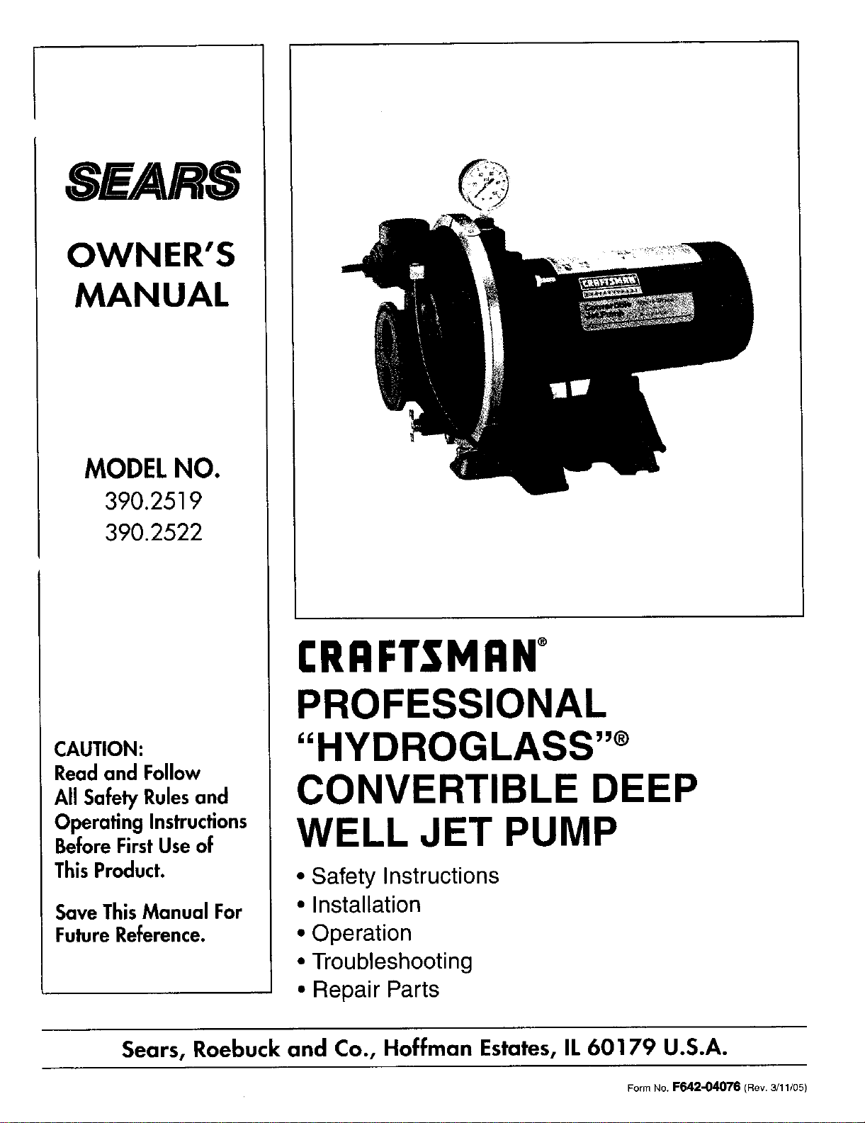
I:RRFTSMRN°
PROFESSIONAL
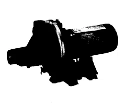
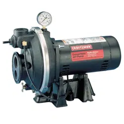
"HYDROGLASS ''®
CONVERTIBLE DEEP
WELL JET PUMP
• Safety Instructions
• Installation
• Operation
• Troubleshooting
• Repair Parts
Sears, Roebuck and Co., Hoffman Estates, IL 60179 U.S.A.
Form No. F642-04076 (Rev. 3/11/05)
READ AND FOLLOW SAFETY INSTRUCTIONS!
A
WARNING 1
A CAUTION 1
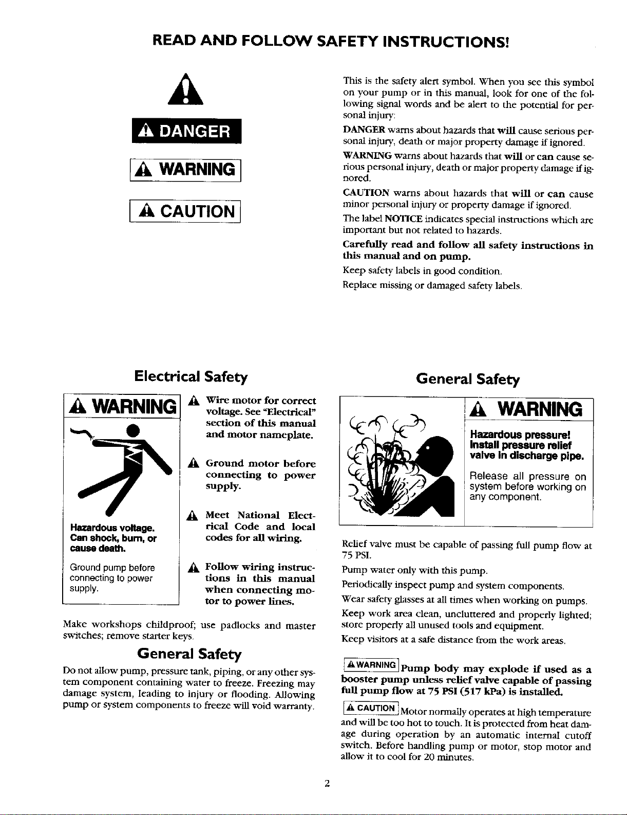
This is the safety alert symbol. When you see this symbol
on your pump or in this manual, look for one of the fol-
lowing signal words and be alert to the potential for per-
sonal injury:
DANGER warns about hazards that will cause serious per-
sonal injury, death or major property damage if ignored.
WARNING warns about hazards that will or can cause se-
rious personal injury, death or major property damage if ig-
nored.
CAUTION warns about hazards that will or can cause
minor personal injury or property damage if ignored.
The label NOTICE indicates special instructions which are
important but not related to hazards.
Carefully read and follow all safety instructions in
this manual and on pump.
Keep safety labels in good condition.
Replace missing or damaged safety labels.
Electrical Safety
A WARNING
Hazardous voltage.
Can shock, bum, or
cause death.
Ground pump before
connecting to power
supply.
_k Wire motor for correct
voltage. See "Electrical"
section of this manual
and motor nameplate.
_k Ground motor before
connecting to power
supply.
Meet National Elect-
rical Code and local
codes for all wiring.
Follow wiring instruc-
tions in this manual
when connecting mo-
tor to power lines.
Make workshops childproof; use padlocks and master
switches; remove starter keys.
General Safety
Do not allow pump, pressure tank, piping, or any other sys-
tem component containing water to freeze. Freezing may
damage system, leading to injury or flooding. Allowing
pump or system components to freeze v_dl void warranty.
General Safety
WARNING
Hazardous pressure!
Install pressure relief
valve In discharge pipe.
Release all pressure on
system before working on
any component.
Relief valve must be capable of passing full pump flow at
75 PSI.
Pump water only with this pump.
Periodically inspect pump and system components.
Wear safety glasses at all times when working on pumps.
Keep work area clean, tmclunered and properly lighted;
store properly all unused tools and equipment.
Keep visitors at a safe distance from the work areas.
AWARNINGIPump body may explode if used as a
I
booster pump unless relief valve capable of passing
full pump flow at 75 PSI (517 kPa) is installed.
[_ CAUTION]Motor normally operates at high temperature
and will be too hot to touch. ]t is protected from heat dam-
age during operation by an automatic internal cutoff
switch. Before handling pump or motor, stop motor and
allow it to cool for 20 minutes.
2
CONTENTS
Safety .................................................................................. 2
Warranty/Introduction ....................................................... 3
Installation ....................................................................... 4-8
Electrical ........................................................................ 9-10
Operation ......................................................................... 11
Maintenance ..................................................................... 11
Service ......................................................................... 12-13
Troubleshooting .......................................................... 14-15
Pump Performance .......................................................... 15
Repair Parts ................................................................. 16-19
INTRODUCTION
We suggest you take a few minutes to read the instructions
contained in this manual before installing and using your
pump. This viifi help you obtain the full benefits of the qual-
ity and convenience built into this equipment. It will also
help you avoid any needless service expense resulting from
causes beyond our control which naturally cannot be cov-
eredinourwarranty.
of charge.
During the Second year and third year from purchase date, a free pump part will be supplied for a defective one.
You must pay the labor cost if you wish to have it installed.
Warranty service is available by returning this product to place of purchase for replacement, or by calling
1-800-4-MY-HOME ®to arrange for part replacement or product repair.
This warranty is VOID if this pump is used for commercial or rental purposes.
Sears is not liable for loss or damage to property, nor for any incidental or consequential loss or expense from
property damage, that results directly or indirectly from the use of this product.
This warranty gives you specific legal rights, and you may also have other fights which vary from state to state.
Sears Roebuck and Co., Dept. 817WA, Hoffman Estates, IL 60179
RULES FOR SAFE INSTALLATION AND OPERATION
1. Read the Owners Manual and Rules for Safe Operation
and Installation Instructions careflifiy. Failure to follow
these Rules and Instructions could cause serious bodily
injury, and/or property damage.
2. Check your local electrical wiring codes before installa-
tion. ffyour local codes are not followed, your pump will
not work to its full rated capacity. If in doubt, contact
your local Power Company.
3. Be certain your pump installation meets all local plumb-
hag, pump and well codes.
4. While installing the pump, always keep the well covered
to prevent leaves and foreign matter from falling into the
well and contaminating the water and/or causing possi-
ble serious damage to the mechanical operation of the
pump.
5. Always test the well water for purity before using. Check
with local health department for testing procedure.
6. Before installing or servicing your pump, BE CERTAIN
pump power source is disconnected.
7. Be sure your pump electrical circuit is properly gruunded.
8. Complete pump and piping system MUST be protected
against below freezing temperature. Failure to do so could
cause severe damage and voids the Warranty.
9. Make sure the line voltage and frequency of the electrical
circuit supply agree with the motor wiring. If motor is
dual voltage type, BE SURE it is wired correctly for your
power supply.
10. The correct fusing and wiring sizing is essential to proper
motor operation. Recommended flWmg and v/ire size data
is in the manual.
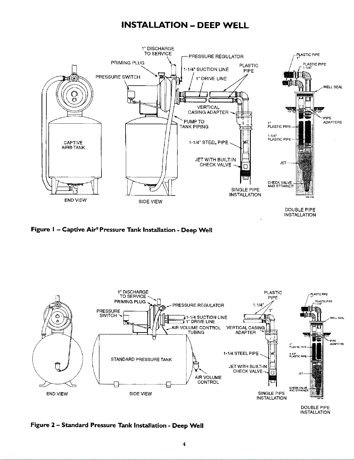
INSTALLATION - DEEP WELL
1" DISCHARGE
TO SERVICE
IE REGULATOR
\
PRIMING PLUG
PLASTIC
_ 1-1/4" SUCTION LINE PIPE
PRESSURE SWITCH !
LINE
\
1,
PLASTIC PIPE
WELLSEAL
CAPTIVE
AIR_ TANK
1-1/4"
CHECK\
1.
PLASTIC PIPE--
1-1/4"
PLASTIC PIP
ADAPTERS
END VIEW
SIDE VIEW
SINGLE PIPE
INSTALLATION
CHECKVALVE_
AND STRAINER
DOUBLE PIPE
INSTALLATION
Figure I - Captive Air'Pressure Tank Installation - Deep Well
1" DISCHARGE
PRIMING PLUG
PRESSURE
SWITCH
STANDARD PRESSURE TANK
D
TO SERVICE _.
-_ "_H_ _- PRESSURE REGULATOR 1-1/4"
_IMING PLUG
1-1/4 SUCTION LINE
_._--IJl !II_:_E==_1"DRIVE LINE
.,_-AIR VOLUME CONTROL VERTICALCASING
_AIR VC TUBING ADAPTER
_AIG 1-1/4 STEEL PIP
JET WITH BUILT-In
CHECK VALVE
AIR VOLUME
ONTROL
END VIEW SIDE VIEW
PLASTIC
PIPE
SINGLE PIPE
INSTALLATION
Figure 2 - Standard Pressure Tank Installation - Deep Well
DOUBLE PIPE
INSTALLATION
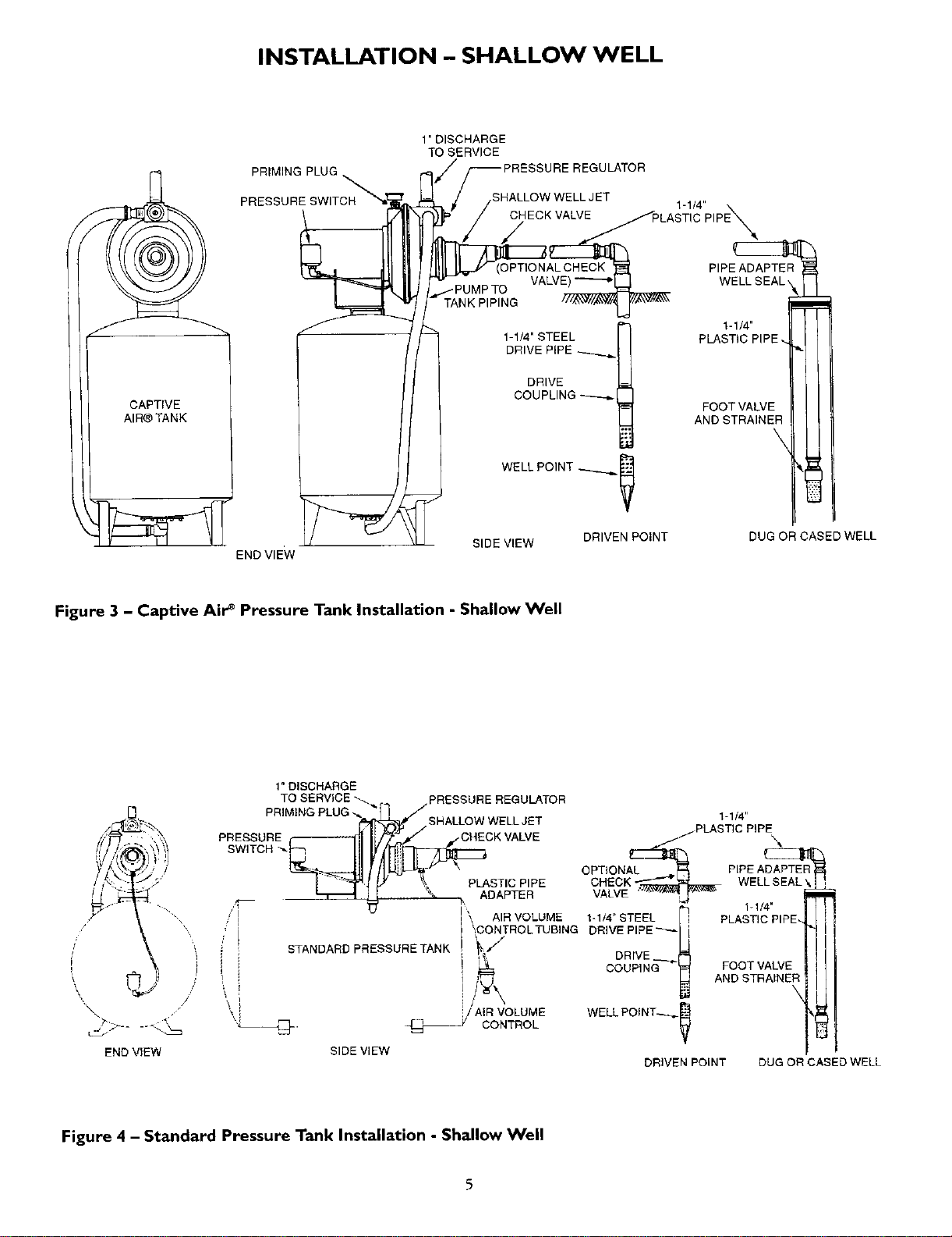
INSTALLATION - SHALLOW WELL
CAPTIVE
AIR®TANK
PRIMING PLUG
PRESSURE SWITCH
END VIEW
1" DISCHARGE
TO SERVICE
ULATOR
L JET
CHECK VALVE
VALVE)
PING
1-1/4' STEEL
DRIVE PiPE
DRIVE
COUPLING
WELL POINT _._
SIDE VIEW DRIVEN POINT
'-"4"p,pE',
PIPE ADAPTER
I
'-"4"l
PLASTIC PIPE. •
FOOT VALVE
AND STRAIN
DUG OR CASED WELL
Figure 3 - Captive Air _ Pressure Tank Installation - Shallow Well
1" DISCHARGE
TO SERVICE _.. PRESSURE REGULATOR
PRIMING
PLUG
_[_f/SHALLOW WELL JET
PRESSURE _SNA:OHWE_K VALVE
SWITCH "__
,-, PLASTIC PIPE
ADAPTER
'I
AIR VOLUME
1-1!4" STEEL i
i CONTROLTUBING DRIVE PIPE_
STANDARD PRESSURE TANK _;; DRIVE __
i_ COUPING
END VIEW SIDE VIEW
/ AiR VOLUME
CONTROL
I-1/4"
j. PLASTIC PIPE,
OPTIONAL 4p PIPE ADAPTER
CHECK
VALVE
1-1/4'
PLASTIC PIPE.
FOOT VALVE
AND STRAINER
WELL POINT--_
DRIVEN POINT DUG OR CASED WELL
Figure 4 - Standard Pressure Tank Installation - Shallow Well
5
INSTALLATION
NOTICE: Use Teflon tape supplied with the pump or Plasto-
Joint Stikl for making all pipe-thread connections to the
pump itself. To avoid stress-cracking, do not use pipe joint
compounds on the pump.
1. Wrap male pipe threads being attached to pump with one
or two layers of Teflon tape. Cover entire threaded por-
tion of pipe.
2. Do not overtighten threaded fittings in the plastic pump.
Be sure you do not try to tighten joint past thread stop in
pump port!
3. If leaks occur, remove fittings, clean off old tape, rewrap
with one to two layers of tape and remake the connec-
tion. If joint still leaks, replace the fittings (fittings may be
undersized).
4. Be sure to support all piping connected to the System.
MAJOR COMPONENTS AND WHAT
THEY DO
Tank and Air Volume Control
The tank serves two functions. It provides a reservoir of
water, some of which can be drawn through the house fix-
ture before the pump must start, and it maintains a cushion
of air under pressure.
When Captive Air +Tanks are used, no air volume control is
necessary. This tank contains a permanent pre-charge of air.
When a Standard Tank is used, an air volume control adds
air to the tank when it is needed. See instructions included
with Air Volume Control for details on installation and op-
eration.
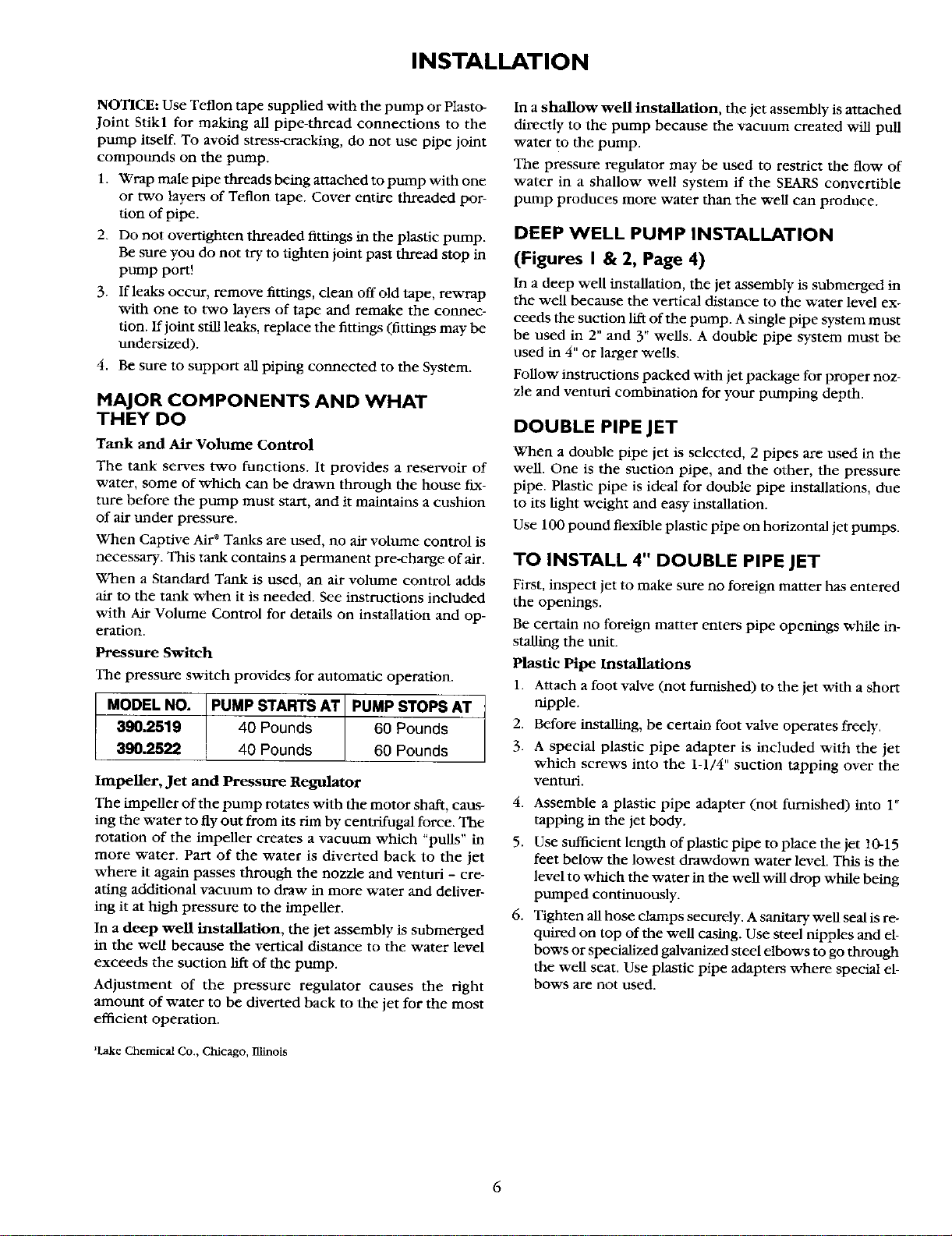
Pressure Switch
The pressure switch provides for automatic operation.
MODEL NO. PUMP STARTS AT PUMP STOPS AT
390.2519 40 Pounds 60 Pounds
390.2522 40 Pounds 60 Pounds
Impeller, Jet and Pressure Regulator
The impeller of the pump rotates with the motor shaft, caus-
ing the water to fly out from its rim by centrifugal force. The
rotation of the impeller creates a vacuum which "puns" in
more water. Part of the water is diverted back to the jet
where it again passes through the nozzle and venturi - cre-
ating additional vacuum to draw in more water and deliver-
ing it at high pressure to the impeller.
In a deep well installation, the jet assembly is submerged
in the well because the vertical distance to the water level
exceeds the suction lift of the pump.
Adjustment of the pressure regulator causes the fight
amount of water to be diverted back to the jet for the most
efficient operation.
_Lake Chemical Co., Chicago, Blinois
In a shallow well installation, the jet assembly is attached
directly to the pump because the vacuum created will pull
water to the pump.
The pressure regulator may be used to restrict the flow of
water in a shallow well system if the SEARS convertible
pump produces more water than the well can produce.
DEEP WELL PUMP INSTALLATION
(Figures I & 2, Page 4)
In a deep well installation, the jet assembly is submerged in
the well because the vertical distance to the water level ex-
ceeds the suction lift of the pump. A single pipe system must
be used in 2" and 3" wells. A double pipe system must be
used in 4" or larger wells.
Follow instructions packed with jet package for proper noz-
zle and venturi combination for your ptmaping depth.
DOUBLE PIPE JET
When a double pipe jet is selected, 2 pipes are used in the
well. One is the suction pipe, and the other, the pressure
pipe. Plastic pipe is ideal for double pipe installations, due
to its light weight mid easy installation.
Use 100 ponnd flexible plastic pipe on horizontal jet pumps.
TO INSTALL 4" DOUBLE PIPE JET
First, inspect jet to make sure no foreign matter has entered
the openings.
Be certain no foreign matter enters pipe openings while in-
stalling the unit.
Plastic Pipe Installations
1. Attach a foot valve (not furnished) to the jet with a short
nipple.
2. Before installing, be certain foot valve operates freely.
3. A special plastic pipe adapter is included with the jet
which screws into the 1-1/4" suction tapping over the
venturi.
4. Assemble a plastic pipe adapter (not furnished) into 1"
tapping in the jet body.
5. Use sufficient length of plastic pipe to place the jet 10-15
feet below the lowest drawdown water level. This is the
level to which the water in the well will drop while being
pumped continuously.
6. Tighten all hose clamps securely. A sanitary well seal is re-
quired on top of the well casing. Use steel nipples and el-
bows or specialized galvanized steel elbows to go through
the well seat. Use plastic pipe adapters where special el-
bows are not used.
6
INSTALLATION
STEEL PIPING INSTALLATIONS
When steel pipe is used to install the jet, be sure all pipes
are clean and the ends are reamed. Screw both 1-1/4" NPT
suction pipe and 1" NPT drive pipe directly into the jet body.
The special adapter nipple furnished with the jet is not used
on steel pipe installations, and should be discarded. Add suf-
ficient piping, using pipe thread compound on the joints
until proper depth is reached.
NOTICE: Pipe compound can damage plastic components
in pump. Use only Teflon tape or Plasto-Joint Stik' when con-
necting pipe to pump.
SINGLE PIPE JETS - 2" OR 3" WELLS
Before installing jet in well, it is necessary to soften jet
leathers by soaking in water for a minimum of one hour.
Single pipe jets must be installed with steel suction piping
in the well. Make sure all pipes are clean and ends are
reamed before lowering any piping into the well. Look
through pipe to make certain there are no obstructions.
During the process of lowering pipe into the well, always in-
stall coupling on top end of pipe and above clamp. This will
prevent accidental dropping of pipe into well.
Attach the jet to the first length of suction pipe 1-1/4" (NF1).
Use turned couplings (furnished) on 2" wells. Standard cou-
plings may be used for suction piping on 3" wells. Use pipe
compound on male threads only.
Tighten each length of pipe as it is lowered into the well.
Lower it to proper depth which is 10-15 feet below the
drawdown water level. This is the level to which the water
will drop while the well is being pumped continuously.
NOTICE: Due to normal irregularities in the leather of the
cup seals and the inner walls of the drop pipe, 2" packer jets
do not form a perfect seal. In a dormant system, water will
leak back into well over time and pump will normaUy start
and cycle to maintain system pressure level.
PRIMING PIPE (OR PIPES) IN WELL
Fill piping in well with water as each length is added, or after
piping is complete in well. This serves to double check for
leaks in piping and foot valve, and simplifies final priming of
pump.
INSTALLING CASING ADAPTER
Slide adapter on to well casing as far as it will go. Tighten
three bolts to seal the adapter to the casing. Place a 1" nip-
ple of proper length in the drive pipe opening in the casing
adapter, and tighten top nuts. This will seal the glands on to
both suction and drive piping. Add elbows and flexible pipe
adapters for horizontal installations.
'Lake Chemical Co., Chicago, Illinois.
SHALLOW WELL INSTALLATION
AND OPERATION
Installing the Pump on a shallow Well
A shallow well jet is available for use when the SEARS jet
pump is installed on wells 20 feet or less to drawdown water
level.
Install this jet as follows:
a. Loosen the stainless steel clamp until it fits over the flange
on the jet body.
b. Place O-Ring in circular groove on face of suction-drive
line flange. If necessary, use petroleum jelly to hold in
place.
c. Venturi that protrudes from the jet body must be inserted
in top (1-1/4" NV_ tapping. For ease of assembly, lubri-
cate the small O-Ring on the end of the venturi and push
the shallow well jet assembly into place.
d. Align lugs on jet body with slots in pump.
e. Place clamp over the flanges and tighten securely.
For standard tank installations, an air volume control is nec-
essary and is connected to the 1/8" tapping in the jet body.
Connect as shown in installation drawing, Figure 4, Page 5.
PIPING IN THE WELL
A shallow well jet pump can be installed on a dug well,
drilled well or with a driven point. SEARS shallow well jet
pumps have a built-in check valve. In a dug or cased well, a
foot valve and strainer is recommended and should be in-
stalled 5 to 10 feet below the lowest level to which the water
will drop while the pump is operating (pumping water
level). See Figure 4, Page 5. Your well driller can furnish this
information. The strainer should not be too close to the bot-
tom, or sediment may clog it. Before installing foot valve,
check to see if it works freely.
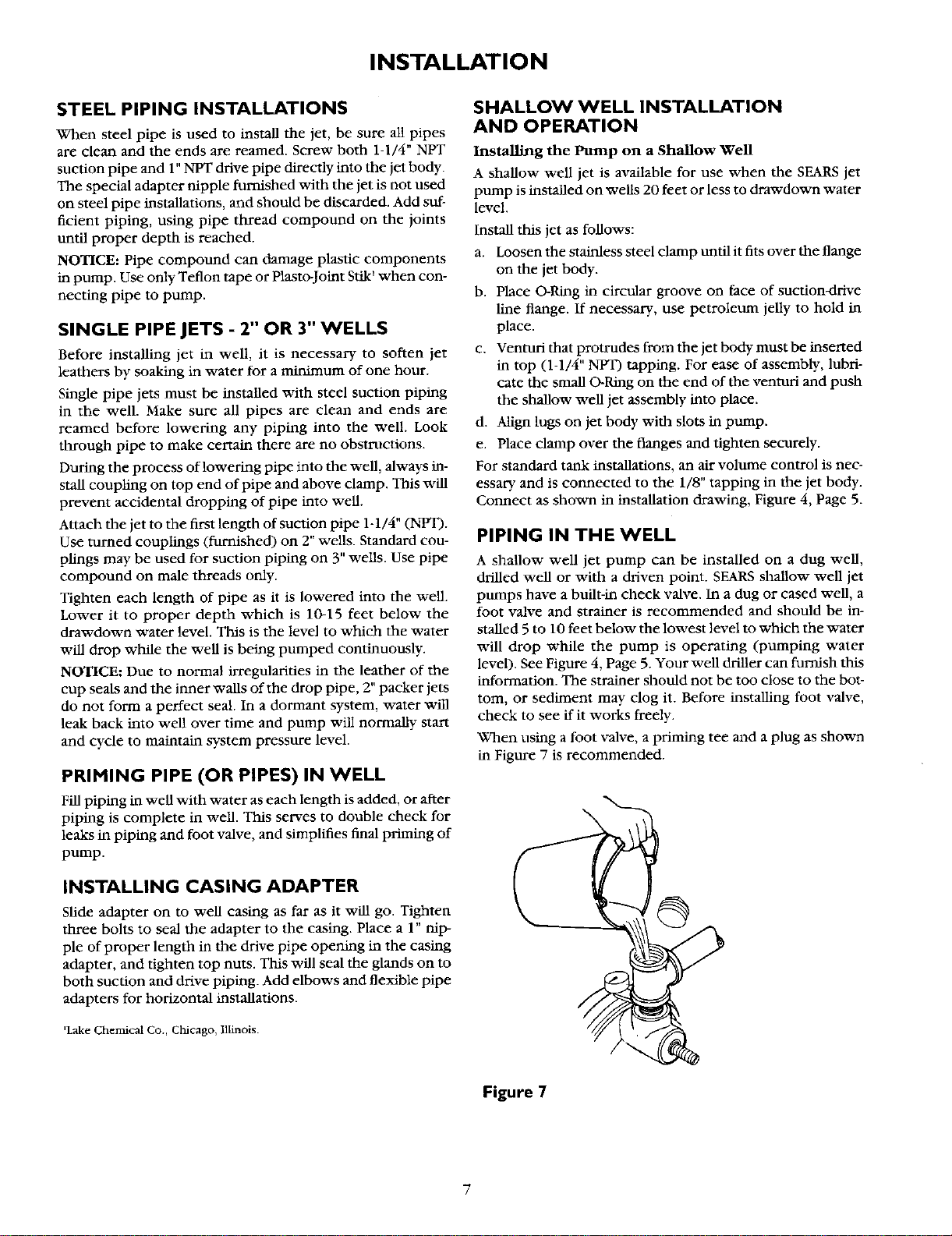
When using a foot valve, a priming tee and a plug as shown
in Figure 7 is recommended.
Figure 7
INSTALLATION
i"_ CAUTION ]NEVER run pump dry. Running pump with-
out water may overheat unit, damaging seals and possibly
burning persons handling pump.
l 1
[_WARNINGJNEVER run pump against closed dis-
charge. To do so can boil water inside pump, causing haz-
ardous pressure in unit and possible scalding to persons
handling pump.
Be sure the total lift from the pumping water level to the
pump does not exceed 20 feet ff the pump is over the well,
or less if the pump is offset from the well. Both figures are
for sea level - the maximum lift at which the pump can op-
erate satisfactorily, decreases with the elevation at the ap-
proximate rate of 1 foot per 1,000 feet of elevation; thus, ff
the lift is 17 feet and your elevation is 3,000 feet above sea
level, you would then be pumping 17 plus 3 or 20 feet,
which is still satisfactory for shallow well pumping.
Horizontal Piping From Well To Pump
On well point installations where the horizontal piping is
more than 25 feet, a check valve should be installed as
shown in Figures 3 and 4, Page 5.
When the pump is offset more than 25 feet from the well,
horizontal piping should be increased in size to reduced fric-
tion losses. In no case should the offset piping be smaller
than the suction tapping of the pump.
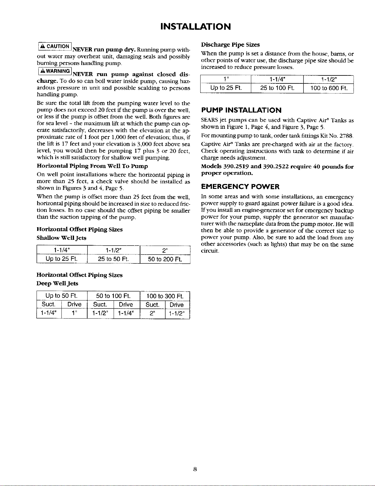
Horizontal Offset Piping Sizes
Shallow Well Jets
1-1/4" 1-1/2" 2"
Up to 25 Ft. 25 to 50 Ft. 50 to 200 Ft.
Horizontal Offset Piping Sizes
Deep Well Jets
Discharge Pipe Sizes
When the pump is set a distance from the house, barns, or
other points of water use, the discharge pipe size should be
increased to reduce pressure losses.
1" 1-1/4" 1-1/2"
Up to 25 Ft. 25 to 100 Ft. 100 to 600 Ft.
PUMP INSTALLATION
SEARS jet pumps can be used with Captive Air s Tanks as
shown in Figure 1, Page 4, and Figure 3, Page 5.
For mounting pump to tank, order tank fittings Kit No. 2788.
Captive Air* Tanks are pre-charged with air at the factory.
Check operating instructions with tank to determine if air
charge needs adjustment.
Models 390.2519 and 390.2522 require 40 pounds for
proper operation.
EMERGENCY POWER
In some areas and with some installations, an emergency
power supply to guard against power failure is a good idea.
If you install an engine-generator set for emergency backup
power for your pump, supply the generator set manufac-
turer with the nameplate data from the pump motor. He will
then be able to provide a generator of the correct size to
power your pump. Also, be sure to add the load from any
other accessories (such as lights) that may be on the same
circuit.
Up to 50 Ft.
Suct. Drive
1-1/4 1"
50 to 100 Ft.
Suct. Drive
1-1/2" 1-1/4"
100 to 300 Ft. I
Suct. Drive
2 1-1/2
8
ELECTRICAL
Disconnect power before working on pump, motor, pressure switch, or wiring.
Motor Switch Settings
If the motor can operate at either 115 or 230 volts, it is set
at the factory to 230 volts. Do not change motor voltage
setting if line voltage is 230 volts, or if you have a single
voltage motor.
NOTICE: Never wire a 115 volt motor to a 230 volt line.
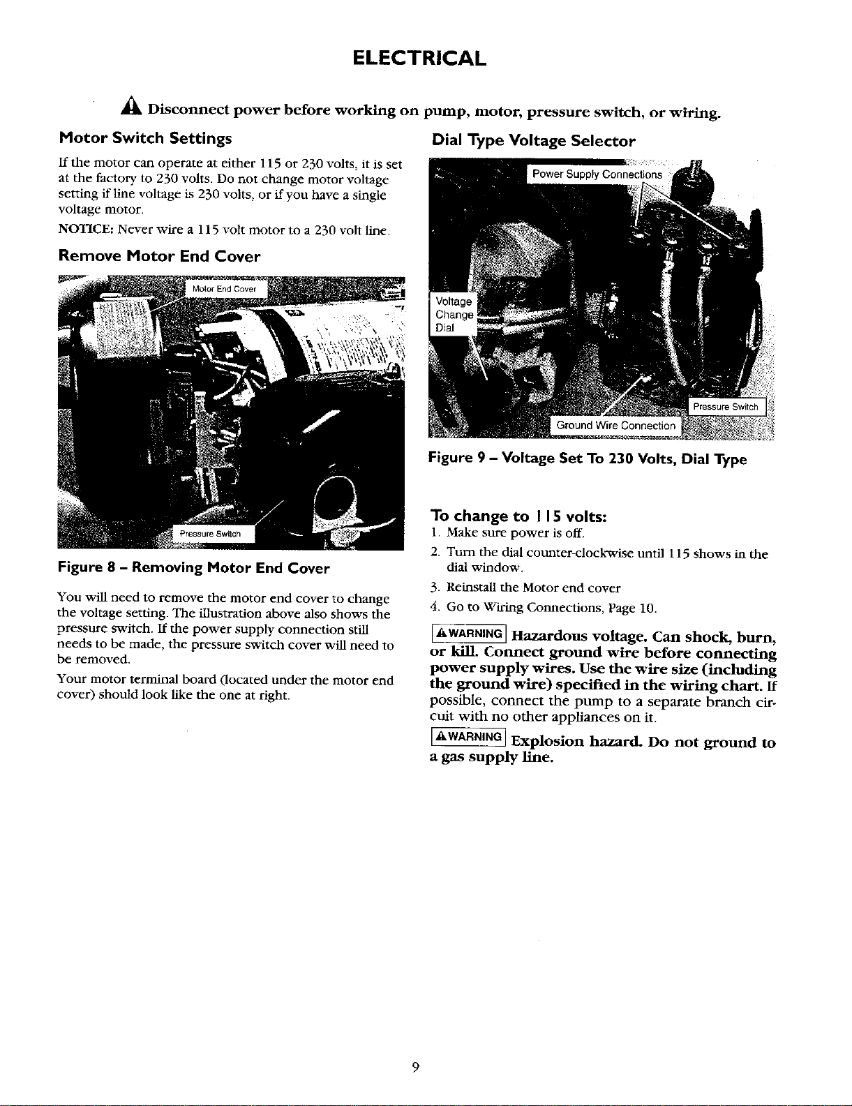
Remove Motor End Cover
Figure 8 - Removing Motor End Cover
Dial Type Voltage Selector
You will need to remove the motor end cover to change
the voltage setting. The illustration above also shows the
pressure switch. If the power supply connection still
needs to be made, the pressure switch cover will need to
he removed.
Your motor terminal board (located under the motor end
cover) should look like the one at right.
Figure 9 - Voltage Set To 230 Volts, Dial Type
To change to I 15 volts:
1. Make sure power is off.
2. Turn the dial counter-clockwise until 115 shows in the
dial window.
3. Reinstall the Motor end cover
4. Go to Wiring Connections, Page 10.
[_kWARNING]Hazardous voltage. Can shock, burn,
or kill. Connect ground wire before connecting
power supply wires. Use the wire size (including
the ground wire) specified in the wiring chart. If
possible, connect the pump to a separate branch cir-
cuit with no other appliances on it.
[,_kWARNING_Explosion hazard. Do not ground to
a gas supply line.
9
ELECTRICAL
Wiring Connections
[*_.WARNING ] Fire hazard. Incorrect voltage can cause
a fire or seriously damage the motor and voids the war-
ranty. The supply voltage must be within _+10% of the
motor nameplate voltage.
NOTICE: Dual-voltage motors are factory wired for
230 volts. If necessary, reconnect the motor for 115
volts, as shown. Do not alter the wiring in single volt-
age motors.
Install, ground, wire, and maintain your pump in com-
pliance with the National Electrical Code (NEC) or the
Canadian Electrical Code (CEC), as applicable, and
with all local codes and ordinances that apply. Consult
your local building inspector for code information.
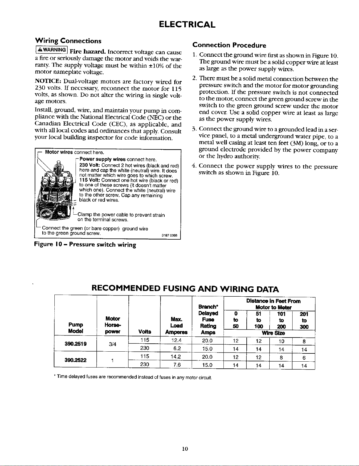
Motor wires connect here.
-Power supply wires connect here.
230 Volt: Connect 2 hotwires (black and red)
here and cap the white (neutral) wire. it does
not matter which wire goes to which screw.
115 Volt: Connect one hot wire (black or red)
to one of these screws (it doesn't matter
which one). Connect the white (neutral) wire
to the other screw. Cap any remaining
black or red wires.
prevent strain
on the terminal screws.
Connect the green (or bare copper) ground wire
tothe green ground screw. 31870398
Figure I0 - Pressure switch wiring
Connection Procedure
1.
2.
.
.
Connect the ground vdre first as shown in Figure 10.
The ground wire must be a soEd copper wire at least
as large as the power supply wires.
There must be a solid metal connection between the
pressure switch and the motor for motor grounding
protection. If the pressure switch is not connected
to the motor, connect the green ground screw in the
switch to the green ground screw under the motor
end cover. Use a solid copper vdre at least as large
as the power supply wires.
Connect the ground wire to a grounded lead in a ser-
vice panel, to a metal undergrotmd water pipe, to a
metal well casing at least ten feet (3/7I) long, or to a
ground electrode provided by the power company
or the hydro authority.
Connect the power supply wires to the pressure
switch as shown in Figure 10.
Pump
Model
390.2519
390.2522
RECOMMENDED FUSING AND WIRING DATA
Motor
Horse-
power
3/4
Volts
115
23O
115
230
Max.
Load
Amperes
12.4
6,2
14,2
7.6
Branch*
Delayed
Fuse
Rating
Amps
20.0
15.0
20.0
15.0
Distancein Feet From
Motorto Meter
0 51 101 201
to to to to
50 100 200 300
Win_Size
12 12 10 8
14 14 14 14
12 12 8 6
14 14 14 14
* Time delayed fuses are recommended instead of fuses in any motor circuit.
10
OPERATION MAINTENANCE
PRIMING THE SHALLOW WELL PUMP
TO PREVENT DAMAGE TO INTERNAL PARTS, DO NOT
START MOTOR UNTIL PUMP HAS BEEN FILLED WITH
WATER.
1. Be sure pressure regulator located on pump body is open
at all times during priming and running. Turn counter-
clockwise all the way.
2. Remove priming plug. Fill pump with water. Replace
priming plug. ff a priming tee and plug have been pro-
vided for a long horizontal run, be sure this line is filled
and the plug replaced, using pipe compound on plug
threads. See Figure 7, Page 7.
3. Start the pump and run for approximately thirty (30) sec-
onds. Stop pump, remove prime plug and refill with
water. Replace prime plug and gauge and restart pump.
Water will be pumped in a few minutes, the time de-
pending on the depth to water and length of horizontal
run. If pump does not prime, check for a possible leak on
the suction side of pump. Check to be sure suction lift -
distance from water level to pump - does not exceed
twenty (20) feet.
PRIMING THE DEEP WELL PUMP
TO PREVENT DAMAGE TO INTERNAL PARTS, DO NOT
START MOTOR UNTIL PUMP HAS BEEN FILLED WITH
WATER.
1. Remove the priming plug. Open pressure regulator (turn
counter-clockwise) located on the pump body. Fill pump
and piping with water and replace plug and tighten only
until it seals.
NOTICE: For location of pressure regulator, see Installation
Diagrams on Pages 4 and 5.
2. Close the pressure regulator (turn clock-vflse).
3. Open several fancets in the house or near the tank to pre-
vent pressure build up in tank.
4. Start pump. Pressure should build up rapidly as the jet and
pump prime. Pressure vddl be in excess of 60 pounds. If
this fails to happen, repeat 2 and 3 above.
5. Once unit has primed on pressure has stabilized, slowly
open (turn cotmter-clockw'tse) the pressure regulator and
water vdfll begin to be pumped into tank.
6. Continue to open pressure regulator until pressure falters
(becomes erratic). At this point, close (turn clockwise)
the pressure regulator slightly until pressure stabilizes.
Close faucets and allow pump to pressurize the tank and
shut off.
7. To insure pump is operating properly, alternately open
and close faucets in system. With faucets open, pressure
will drop until pressure switch starts pump; and with
faucets closed, pressure will build up until pressure
switch shuts off pump.
8. There are certain conditions of deep well operation
whereby the pressure regulator can be completely open
without any faltering of pressure and ff so, pump should
be operated in this manner.
LUBRICATION
It is not necessary to lubricate the pump or its motor. The
motor has two bali bearings lubricated for life. The me-
chanical shaft seal in the pump is water lubricated mad self-
adjusting.
DRAINING FOR WINTER
When the pump is to be disconnected from service, or is in
danger of freezing, it should be drained. The pump has a
drain cock which must be opened. Remove the priming
plug to vent the pump. Drain the pressure tank. Drain all pip-
ing to a point below the freeze line.
To drain an air volume control, remove AVC tnbing and turn
(loosen) it 180 ° on the 1/4" pipe fitting in the tank. This vdll
permit any water remaining in the air volume control to
drain back into the tank.
DISASSEMBLY AND ASSEMBLY OF PUMP
The SEARS Hydroglass* pump is designed for ease in servic-
ing and maintenance.
1. Disassemble pump as follows:
A. Disconnect power.
B. Drain pump by opening drain cock on bottom of
pump body and remove pressure switch tubing from
fitting on top of pump body. This will allow air to re-
place the water in the pump.
C. Remove clamp, Key No. 11, Page 16, which holds the
two pump halves together.
D. Remove pump base mounting bolts. Motor assembly and
back half of pump can now be pulled away from pttmp
front half. Carefully remove O-Ring and place in a clean
area. Inside of pump is now accessible for service.
2. Reassembly of pump.
A. With a clean cloth, wipe out all foreign material from
the large O-Ring groove on the pump back half. Also
wipe clean the large O-Ring and also the small O-Ring,
Key No. 6, Page 16 on the difflaser, Key No. 10, Page
16. This will insure a good tight seal.
B. Lubricate O-Rings with petroleum jelly for ease of as-
sembly. Place large O-Ring in groove.
C. Pump halves can now be slid together tmtil they are
parallel and are as close together as possible.
D. BE SURE inside of clamp is clean. Place clamp on
pump halves and snug up. Alternately tighten clamp
screw and tap around outside of clamp with a plastic
mallet. This will insure proper seating of O-Ring and
clamp.
E. Assemble base mounting bolts. Reconnect pressure
switch tubing and tighten drain cock.
F. Reprime pump and turn on power.
11
SERVICE
REMOVING MOTOR FOR SERVICE
AND REPLACING SHAFT SEAL
Should repair or replacement of motor or seal be necessary,
the pump need not be disconnected from the piping.
(If it is necessary to repair or replace the motor, ALWAYS re-
place the shaft seal, Key No. 7, Page 16. Therefore, we sug-
gest that you order this item and have on hand for future
use).
Remove motor as follows:
1. Disassemble pump per disassembly instruction on Page 11.
2. Remove diffuser and impeller, Key Nos. 8 and 9, Page 16,
from pump back half.
Remove Impeller as follows:
1. Loosen two-machine screws and remove the motor
canopy, Key No. 1A, Page 16.
2. Partially unscrew capacitor clamp and move capacitor to
one side.
3. Place a 7/16" open end wrench on the motor shaft flat.
4. To remove, turn the impeLler counterclockwise (when
facing impeller).
The seal consists of two parts, a rotating member and a float-
ing seat.
NOTICE: The highly polished and lapped faces of the sea! are
easily damaged. Read instructions careful!y.
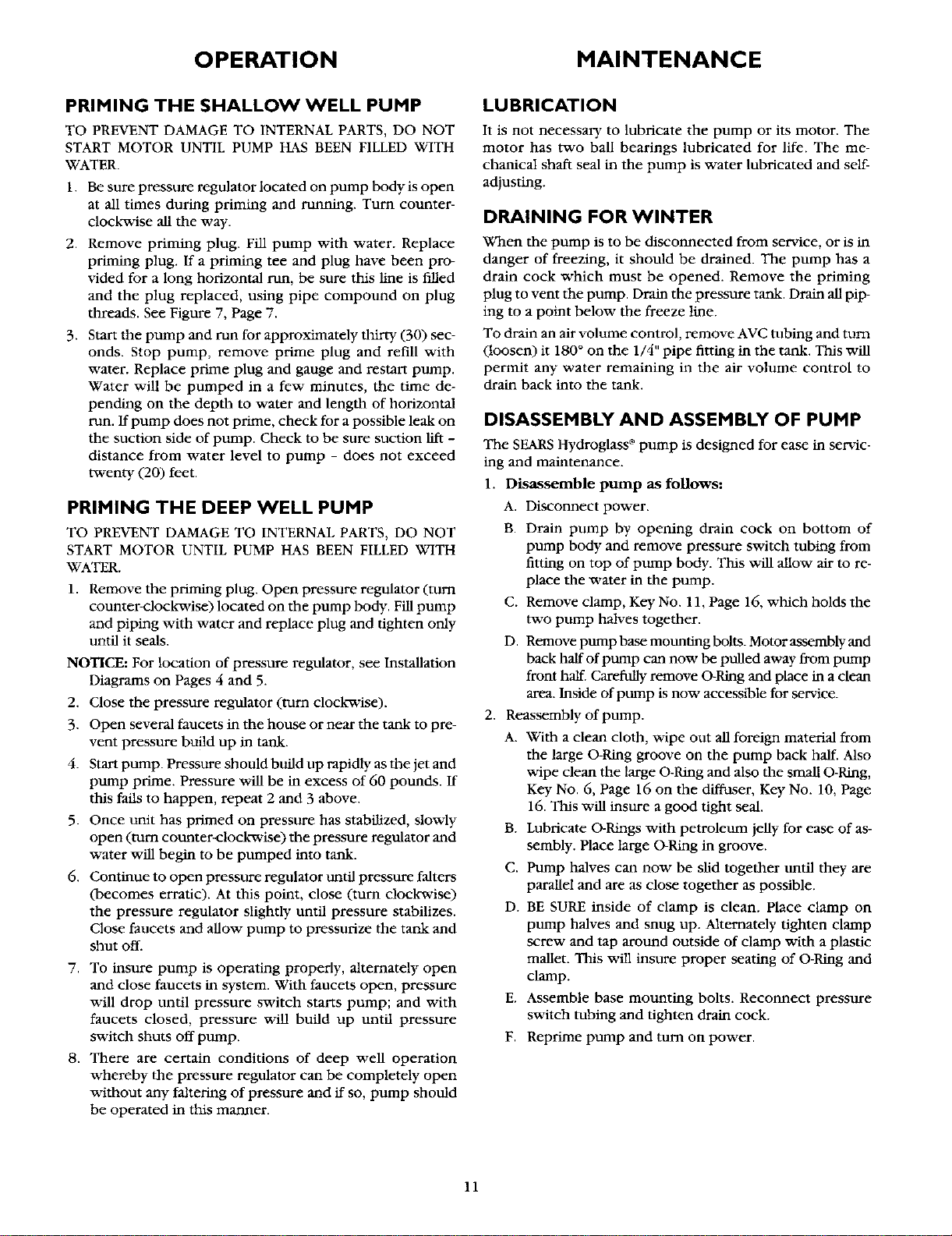
5. Remove pump back half from motor by unscrew'rag four
(4) nuts, Key No. 20, Page 16, and pry back half off of
motor by inserting two (2) screwdrivers between the
back pump half and the motor flange. Rotating portion of
seal vdll now come off of shaft. Motor is now separated
from pump (see Figure 11).
6. Lay back half of pump (large surface down) on a flat clean
surface and tap out ceramic seat. Clean seal cavity from
which seal was removed and clean motor shaft.
Install New Seal As Follows:
1. Clean polished surface of floating seat with clean cloth.
2. Wet the outer edge of the O-Ring on the stationary seat
with soap solution.
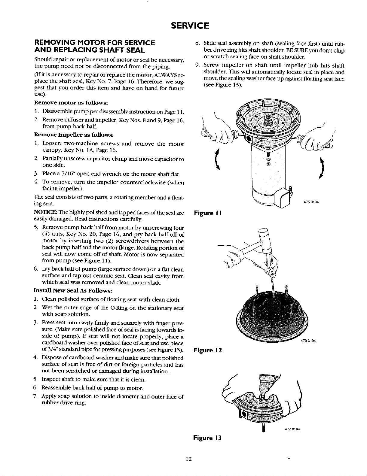
3. Press seat into cavity firmly and squarely with finger pres-
sure. (Make sure polished face of seal is facing towards in-
side of pump). If seat will not locate properly, place a
cardboard washer over polished face of seat and use piece
of 3/4" standard icdlpefor pressing purposes (see Figure 13)-
4. Dispose of cardboard washer and make sure that polished
surface of seat is free of dirt or foreign particles and has
not been scratched or damaged during installation.
5. Inspect shaft to make sure that it is dean.
6. Reassemble back half of pump to motor.
7. Apply soap solution to inside diameter and outer face of
rubber drive ring.
8. Slide seal assembly on shaft (sealing face first) until rub-
ber drive ring hits shaft shoulder. BE SURE you don't chip
or scratch sealing face on shaft shoulder.
9. Screw impeller on shaft until impeller hub hits shaft
shoulder. This v_tll automatically locate seal in place and
move the sealing washer face up against floating seat face
(see Figure 13).
)
Figure II
475 0194
Figure 12
479 0194
Figure 13
477 0194
12
SERVICE
CLEANING IMPELLER
1. Disassemble pump per disassembly instruction on Page 11.
2. Remove diffuser and impeller from pump.
3. Clean impeller and reassemble,
CLEANING SHALLOW WELL JET
To remove a stone or other foreign matter from venturi or
nozzle, proceed as follows:
1. Disconnect power, and release all pressure on system.
2. If pump has an air volume control, unscrew compression
nut from fitting in lower portion of jet body. Tube will not
pull out of fitting.
3. Remove suction piping from pump.
4. Remove stainless steel clamp and remove the jet assem-
bly by pulling it STRAIGHT out and away from the pump
body.
5. Turn venturi counter-clockwise and remove it. Tile noz-
zle is now exposed and should also be removed by using
a 5/8" Hex socket wrench with extension. Turn counter-
clockwise. If socket wrench is not available, insert an ice
pick, or other similar pointed tool carefully into the noz-
zle. This will dislodge foreign material.
6. Flush foreign material out by running water through the
nozzle in the smue direction as the dislodging tool was in-
serted. Jet body should be in a horizontal position for
flushing.
7. Replace nozzle and venturi.
8. Replace jet assembly as explained under "Installing the
pump on a shallow well," Page 7.
CLEANING DEEP WELL JET
1. Disconnect power.
2. Disconnect piping and well seal or well casing adapter.
Of pitless adapter is used, piping does not have to be dis.
connected).
3. Withdraw jet assembly from well.
4. Unscrew and remove the venturi. Remove nozzle with a
socket wrench, if possible, and clean. If nozzle cannot be
removed, clean as explained in steps 5, 6, and 7 reader
Cleaning Shallow Well Jet section above.
HOW TO AVOID OVER-PUMPING
A SHALLOW WELL
In the section on Priming The Shallow Well Pump, Page
10, the instructions were to open the pressure regulator all
the way after the pump starts to deliver water. If you are
over-pumping your well, however, you can partially close
the pressure regulator on your SEARS jet pump to increase
the pressure and reduce the delivery.
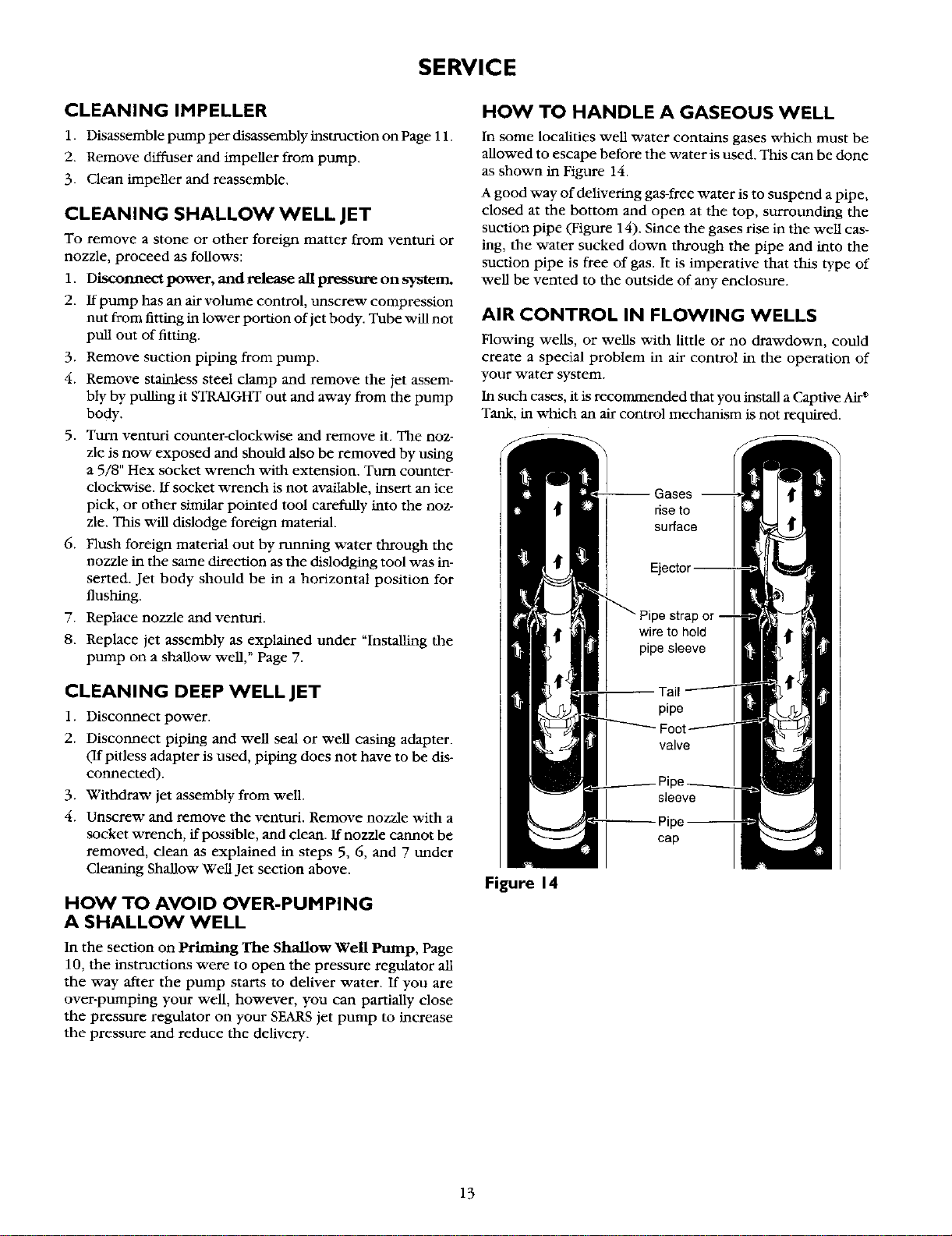
HOW TO HANDLE A GASEOUS WELL
In some localities well water contains gases which must be
allowed to escape before the water is used. This can be done
as shown in Figure 14.
A good way of delivering gas-free water is to suspend a pipe,
closed at the bottom and open at the top, surrounding the
suction pipe (Figure 14). Since the gases rise in tile well cas-
ing, the water sucked clown through the pipe and into the
suction pipe is free of gas. It is imperative that this _'pe of
well be vented to the outside of any enclosure.
AIR CONTROL IN FLOWING WELLS
Flowing wells, or wells with little or no drawdown, could
create a special problem in air control in the operation of
your water system.
In such cases, it is recommended that you install a Captive
Tank, in which an air control mechanism is not required.
strap or
cap
Figure 14
13
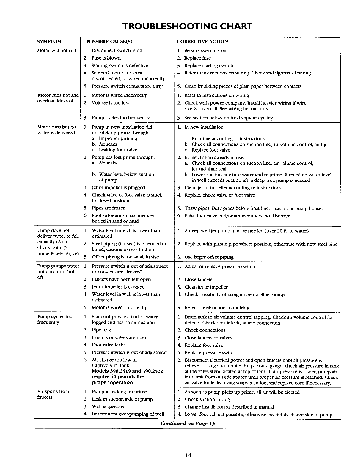
TROUBLESHOOTING CHART
SYMPTOM POSSIBLE CAUSE(S) CORRECTIVE ACTION
Motor will not run 1. Disconnect switch is off 1. Be sure switch is on
2. Fuse is blown 2. Replace fuse
3. Starting switch is defective 3. Replace starting switch
4. Wires at motor are loose, 4. Refer to instructions on wiring. Check and tighten all wiring.
disconnected, or wired incorrectly
Pressure switch contacts are dirty 5. Clean by sliding pieces of plain paper between contacts
Motor is v_lred incorrectly 1. Refer to instructions on wiring
Voltage is too low 2. Check with power company. Install heavier wiring if wire
size is too small. See wiring instructions
Pump cycles too frequently 3. See section below on too frequent cycling
1. In new installation:
5.
Motor runs hot and 1.
overload kicks off 2.
3.
Motor runs but no 1.
water is delivered
2.
3.
4.
5.
6.
pump does not 1.
deliver water to full
capacity (Also 2.
check point 3
inlmediately above) 3.
Pump pttmps water 1.
but does not shut
i off 2.
3.
4.
5.
Pump cycles too 1.
frequently
2.
3.
4.
5.
6.
] Air spurts from 1.
faucets 2.
3.
4.
Pump in new installation did
not pick up prime through:
a, Improper priming
b. Air leaks
c. Leaking foot valve
Pump has lost prime through:
a. Air leaks
b. Water level below suction
of pump
Jet or impeller is plugged
Check valve or foot valve is stuck
in closed position
Pipes are frozen
Foot valve and/or strainer are
buried in sand or mud
Water level in well is lower than
estimated
Steel piping (if used) is corroded or
limed, causing excess friction
Offset piping is too small in size
Pressure switch is out of adjustment
or contacts are "frozen"
Faucets have been left open
Jet or impeller is clogged
Water level in well is lower than
estimated
Motor is wired incorrectly
Standard pressure tank is water-
logged and has no air cushion
Pipe leak
Faucets or valves are open
Foot valve leaks
Pressure switch is out of adjustment
Air charge too low in
Captive Air* Tank
Models 390.2519 and 390.2522
require 40 pounds for
proper operation
Pump is picking up prime
Leak in suction side of pump
Well is gaseous
intermittent over-pumlYmg of well
1.
2.
3.
4.
Continued on Page 15
a. Re-ptime according to instructions
b. Check all connections on suction line, air voltlme control, and jet
c. Replace foot valve
2. In installation already in use:
a. Check all connections on suction line, air volume control,
jet and shaft seal
b. Lower suction line into water and re-prime. If receding water level
in well exceeds suction lift, a deep well pump is needed
3. Clean jet or impeller according to instructions
4. Replace check valve or foot valve
5. Thaw pipes. Bury pipes below frost line. Heat pit or pump house.
6. Raise foot valve and/or strainer above well bottom
1. A deep well jet pump may be needed (over 20 ft. to water)
2. Replace with plastic pipe where possible, otherwise with new steel pipe
3. Use larger offset piping
1. Adjust or replace pressure switch
2. Close faucets
3. Clean jet or impeller
4. Check possibility of using a deep well jet pump
5. Refer to instructions on wiring
1. Drain tank to air volume control tapping. Check air volume control for
defects. Check for air leaks at any connection
2. Check connections
3. Close faucets or valves
4. Replace foot valve
5. Replace pressure switch
6. Disconnect electrical power and open faucets until all pressure is
relieved. Using automobile tire pressure gauge, check air pressure in tank
at the valve stem located at top of tank. If air pressure is lower, pump air
into tank from outside source until proper air pressure is reached. Check
air valve for leaks, using soapy solution, and replace core if necessary.
As soon as pump picks up prime, all air will be ejected
Check suction piping
Change installation as described in manual
Lower foot valve if possible, otherwise restrict discharge side of pump
14
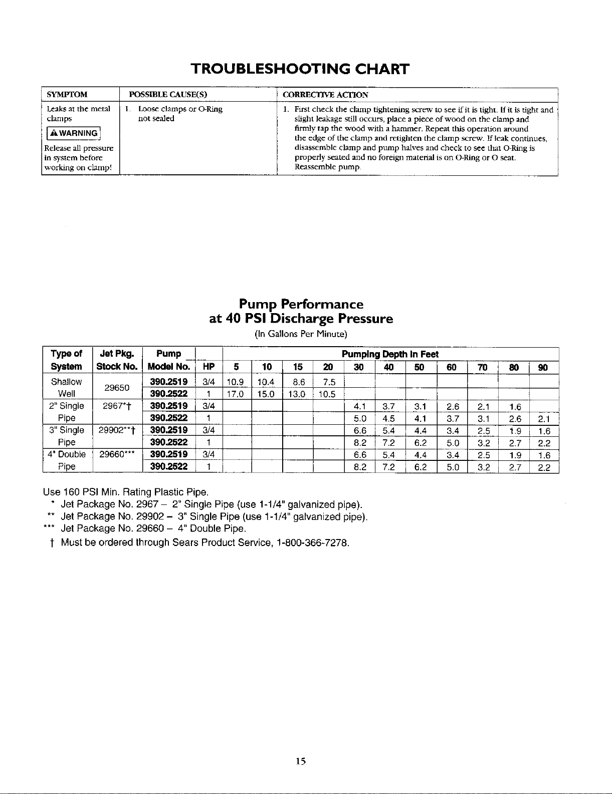
TROUBLESHOOTING CHART
SYMPTOM CORRECTIVE ACTION
Leaks at the metal
clamps
[.WARNING]
Release all pressure
in system before
working on clamp!
POSSIBLE CAUSE(S)
I. Loose damps or O-Ring
not sealed
1. First check the clamp tightening screw to see flit is tight, flit is tight and
slight leakage still occurs, place a piece of wood on the clamp and
firmly tap the wood with a hammer. Repeat tlxis operation around
the edge of the clamp and retighten the clamp screw. If leak continues,
disassemble clamp and pump halves and check to see that O-Ring is
properly seated and no foreign material is on O-Ring or O seat.
Reassemble pump.
Pump Performance
at 40 PSI Discharge Pressure
(In Gallons Per Minute)
Type of Jet Pkg. Pump _ Pumping Depth In Feet
System Stock No. Model No. HP 5 10 15 20 30 40 50 60 70 80 90
Shallow 390.2519 3/4 10.9 10.4 8.6 7.5
29650
Well 390.2522 1 17.0 15.0 13.0 10.5
2" Single 2967"t 390.2519 3/4 4,1 3.7 3.1 2.6 2.1 1.6
Pipe 390.2522 1 5.0 4.5 4.1 3.7 3.1 2.6 2.1
3" Single 29902"*t 390.2519 3/4 6.6 5.4 4.4 3.4 2.5 1.9 1.6
Pipe 390.2522 1 8.2 7.2 6.2 5.0 3.2 2.7 2.2
4" Double 29660*** 390.2519 3/4 6.6 5.4 4.4 3.4 2.5 1.9 1.6
Pipe 390.2522 1 8.2 7.2 6.2 5.0 3.2 2.7 2.2
Use 160 PSI Min. Rating Plastic Pipe.
* Jet Package No. 2967 - 2" Single Pipe (use 1-1/4" galvanized pipe).
** Jet Package No. 29902 - 3" Single Pipe (use 1-1/4" galvanized pipe).
*** Jet Package No. 29660 - 4" Double Pipe.
t Must be ordered through Sears Product Service, 1-800-366-7278.
15
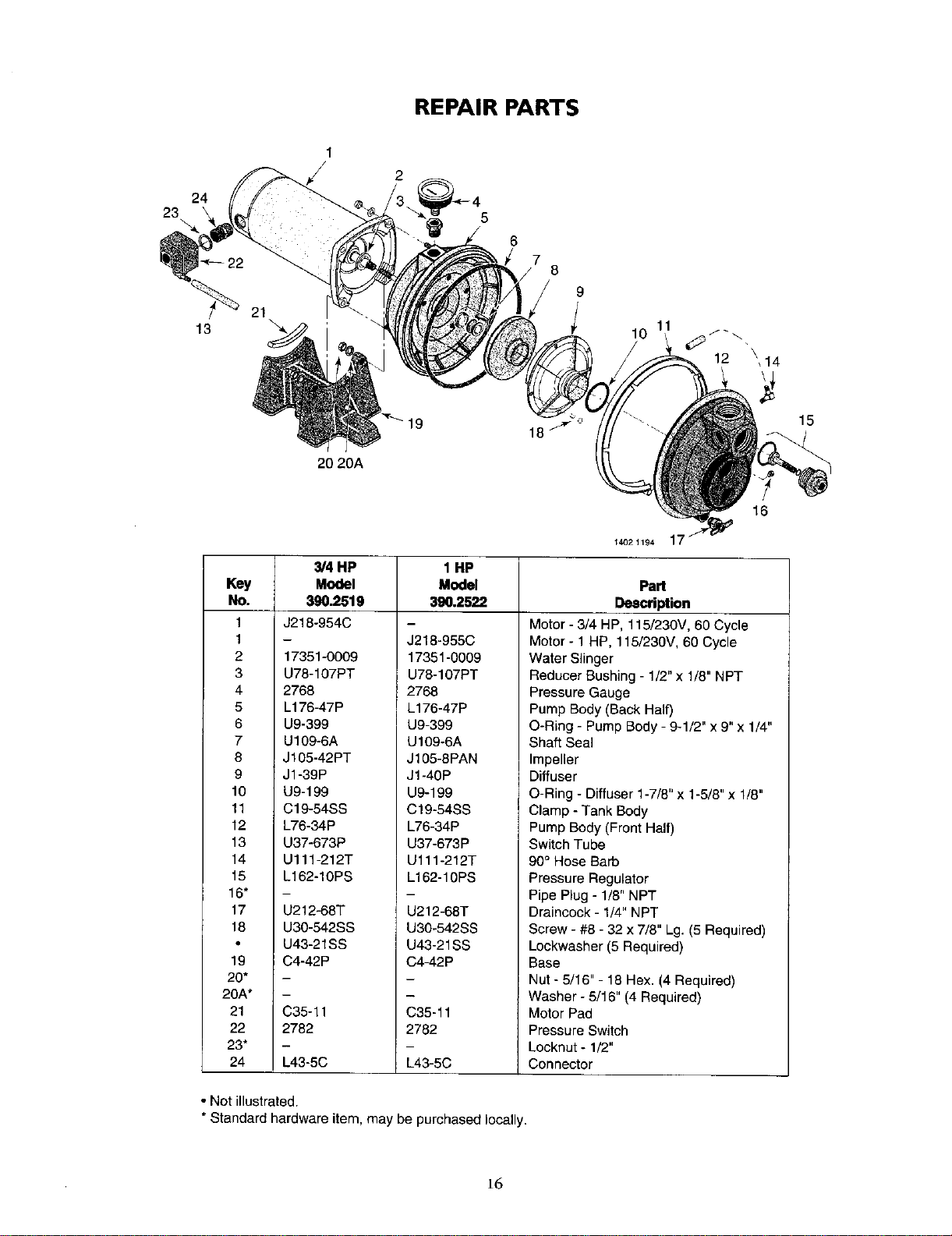
REPAIR PARTS
23
24
22
13
21
\
5
6
/7 8
9
10
11
12 \,14
15
16
Key
No.
1
1
2
3
4
5
6
7
8
9
10
11
12
13
14
15
16"
17
18
19
20*
20A*
21
22
23*
24
14021194 1
3/4 HP 1 HP
Model Model
390.2519 390.2522
J218-954C
17351-0009
U78-107PT
2768
L176-47P
U9-399
U109-6A
J105-42PT
J1-39P
U9-199
C19-54SS
L76-34P
U37-673P
U111-212T
L162-10PS
U212-68T
U30-542SS
U43-21SS
C4-42P
C35-11
2782
m
L43-5C
J218-955C
17351-0009
U78-107PT
2768
L176-47P
U9-399
U109-6A
J105-8PAN
J1-40P
U9-199
C19-54SS
L76-34P
U37-673P
U111-212T
L162-10PS
U212-68T
U30-542SS
U43-21SS
C4-42P
C35-11
2782
L43-5C
Part
Description
Motor - 3/4 HP, 115/230V, 60 Cycle
Motor - 1 HP, 115/230V, 60 Cycle
Water Slinger
Reducer Bushing - 1/2"x 1/8" NPT
Pressure Gauge
Pump Body (Back Half)
O-Ring - Pump Body - 9-1/2" x 9" x 1/4"
Shaft Seal
Impeller
Diffuser
O-Ring - Diffuser 1-7/8" x 1-5/8" x 1/8"
Clamp - Tank Body
Pump Body (Front Half)
Switch Tube
90° Hose Barb
Pressure Regulator
Pipe Plug - 1/8" NPT
Draincock - 1/4" NPT
Screw - #8 - 32 x 7/8" Lg. (5 Required)
Lockwasher (5 Required)
Base
Nut - 5/16"- 18 Hex. (4 Required)
Washer - 5/16" (4 Required)
Motor Pad
Pressure Switch
Locknut- 1/2"
Connector
• Not illustrated.
* Standard hardware item, may be purchased locally.
16
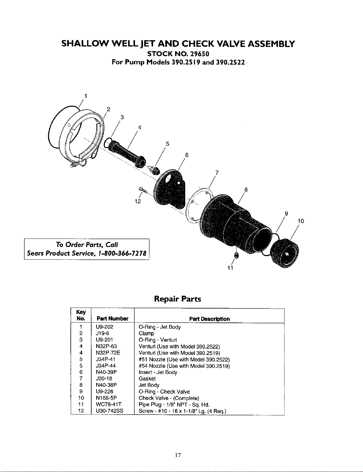
SHALLOW WELL JET AND CHECK VALVE ASSEMBLY
STOCK NO. 29650
For Pump Models 390.2519 and 390.2522
1
/
2
3
/
12
To Order Parts, Call
Sears Product Service, 1-800-366- 7278
4
5
/
7
/
/
11
8
g
10
/
Key
No. Part Number
1 U9-202
2 J19-6
3 U9-201
4 N32P-63
4 N32P-72E
5 J34P-41
5 J34P-44
6 N40-39P
7 J20-18
8 N40-38P
9 U9-226
10 N166-5P
11 WC78-41T
12 U30-742SS
Repair Parts
Part Description
O-Ring - Jet Body
Clamp
O-Ring - Venturi
Venturi (Use with Model 390.2522)
Venturi (Use with Model 390.2519)
#51 Nozzle (Use with Model 390.2522)
#54 Nozzle (Use with Model 390.2519)
Insert - Jet Body
Gasket
Jet Body
O-Ring - Check Valve
Check Valve - (Complete)
Pipe Plug - 1/8" NPT - Sq. Hd.
Screw - #10 - 16 x 1-1/8" Lg. (4 Req.)
1"7
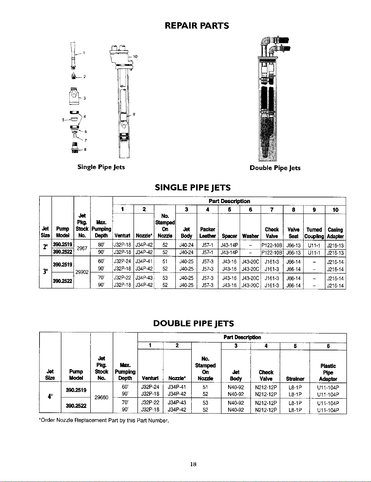
REPAIR PARTS
Single Pipe Jets
Double Pipe Jets
SINGLE PIPE JETS
Part Description
1 2 3 4 5 6 7 8 g 10
Jet No.
Pkg. Max. Stamped
Jet Pump Stock Pumping On Jet Packer Check Valve Turned Casing
Size Modat No. Depth Venturl Nozzle* Nozzle Body Leather Spacer Washer Valve Seat CouplingAdapter
2" 390,2519 2967 80' J32P-18 J34P-42 52 J40-24 J57-1 J43-14P IP122-10B J66-13 Ul1-1 J216-13
390.2522 90' J32P-18 J34P-42 52 J40-24 J57-1 J43-14P _122-10B J66-13 Ul1-1 J216-13
60' J32P-24 J34P-41 51 J40-25 J57-3 - J216-14
390.2519
90' J32P-18 J34P-42 52 J40-25 J57-3 - J216-14
3" -- 29902
70' J32P-22 J34P-43 53 J40-25 J57-3 - J216-14
380,2522
90' J32P-18 J34P-42 52 J40-25 J57-3 - J216-14
J43-16 J43-20C J161-3 J66-14
J43-16 J43-20C J161-3 J66-14
J43-16 J43-20C J161-3 J66-14
J43-16 J43-20C J161-3 J66-14
DOUBLE PIPE JETS
Jet
Pkg. Max.
Jet Pump Stock Pumping
S_e Model No. Depth
60'
390.2519
90'
4" 29660
70'
390.2522
90'
Venturl
J32P-24
J32P-18
J32P-22
J32P-18
Now.le*
J34P-41
J34P-42
J34P-43
J34P-42
NO,
stam_
On
Nozzle
51
52
53
52
PartDascrl_on
3 4
Jet Check
Body Valve
N40-92 N212-12P
N40-92 N212-12P
N40-92 N212-12P
N40-92 N212-12P
5
81tainer
L8-1P
L8-1P
L8-1P
L8-1P
*Order Nozzle Replacement Part by this Part Number.
6
Plastic
_pe
Adapt_
U11-104P
U11-104P
U11-104P
U11-104P
18
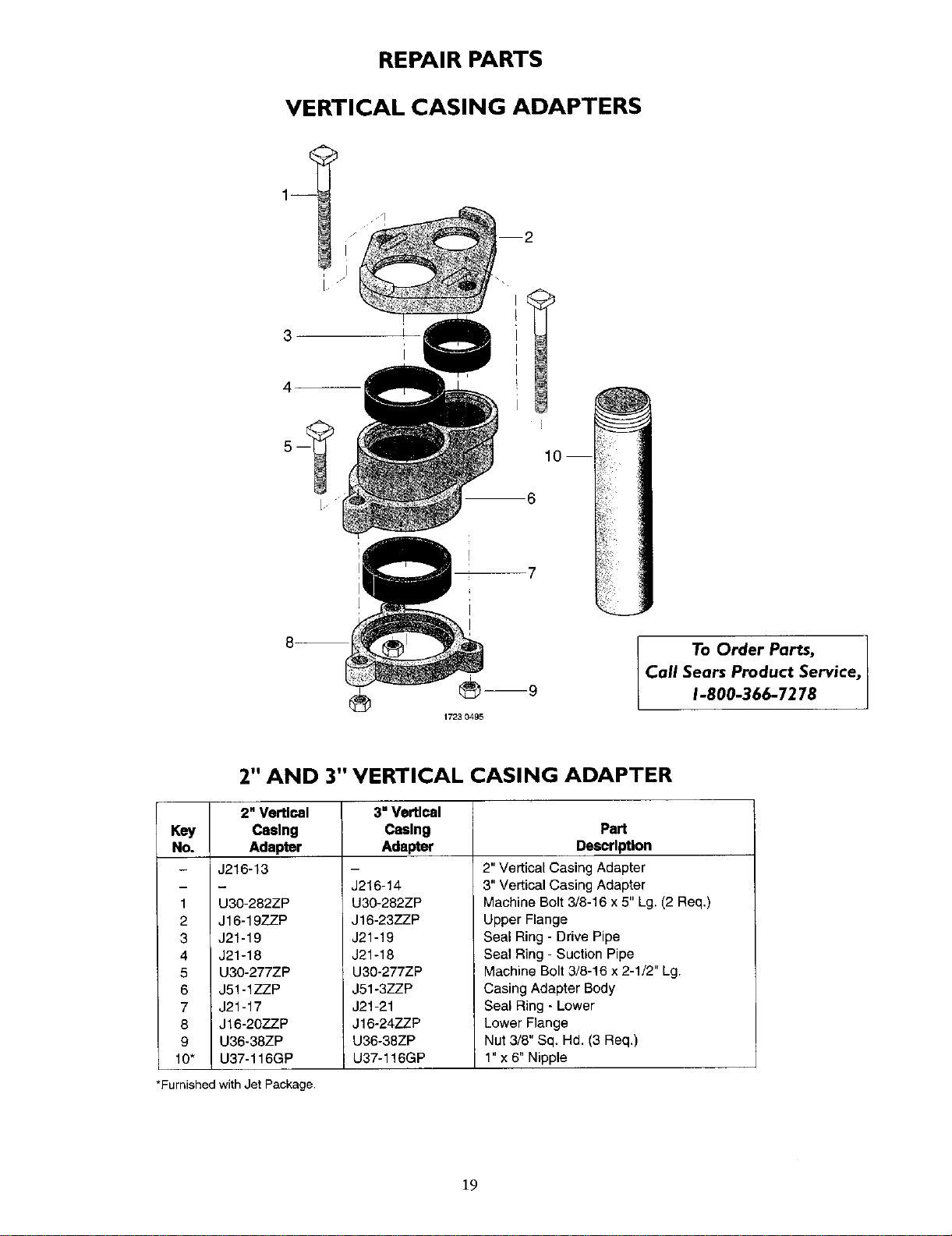
REPAIR PARTS
VERTICAL CASING ADAPTERS
7
_m9
17230495
Call
To Order Parts,
Sears Product Service,
1-800-366-7278
2" AND 3" VERTICAL CASING ADAPTER
2" Vertical 3" Vertlcal
Key Casing Casing Part
No. Adapter Adapter Descrlpt|on
- J216-13
1 U3O-282ZP
2 J16-19ZZP
3 J21-19
4 J21-18
5 U3O-277ZP
6 J51-1ZZ.P
7 J21-17
8 JJ16-20ZZP
9 U36-38ZP
10" U37-116GP
J216-14
U30-282ZP
J16-23ZZP
J21-19
J21-18
U30-277ZP
J51-3ZZP
J21-21
J16-24ZZP
U36-38ZP
U37-116GP
2" Vertical Casing Adapter
3" Vertical Casing Adapter
Machine Bolt 3/8-16 x 5" Lg. (2 Req,)
Upper Flange
Seal Ring - Drive Pipe
Seal Ring - Suction Pipe
Machine Bolt 3/8-16 x 2-1/2" Lg.
Casing Adapter Body
Seal Ring - Lower
Lower Flange
Nut 3/8" Sq. Hd. (3 Req,)
l"x 6" Nipple
*Furnished with Jet Package.
19
Your Home
For repair-in your home-of all major brand appliances,
lawn and garden equipment, or heating and cooling systems,
no matter who made it, no matter who sold it!
For the replacement parts, accessories and
owner's manuals that you need to do-it-yourself.
For Sears professional installation of home appliances
and items like garage door openers and water heaters.
1-800-4-MY-HOME ® (1-800-469-4663)
Call anytime, day or night (U.S.A. and Canada)
www.sears.com www.sears.ca
Our Home
For repair of carry-in items like vacuums, lawn equipment,
and electronics, call or go on-line for the location of your nearest
Sears Parts & Repair Center.
1-800-488-1222
Call anytime, day or night (U.S.A. only)
www.sears.com
To purchase a protection agreement (U.S.A.)
or maintenance agreement (Canada) on a product serviced by Sears:
1-800-827-6655 (U.S.A.) 1-800-361-6665 (Canada)
Au Canada pour service en francq_is:
1-800-LE-FOYER _C
(1-800-533-6937)
www.sears.ca
Para pedir servicio de reparacion
a domicilio, y para ordenar piezas:
1-888-SU-HOGAR _
Sesir-s
® Registered Trademark / TM Trademark / sMService Mark of Sears, Roebuck and Co.
TM S_
® Marca Registrada / Marca de F_brica / Marca de Servicio de Sears, Roebuck and Co.
MCMarque de commerce / MOMarque d6pos6e de Sears, Roebuck and Co. © Sears, Roebuck arid Co.