
USER MANUALUSER MANUAL
AIRTITAN SERIES
CRAWLSPACE AND BASEMENT VENTILATION FANS


3
WELCOME
Thank you for choosing AC Infinity. We are committed to product quality and friendly customer service.
If you have any questions or suggestions, please don’t hesitate to contact us. Visit www.acinfinity.com
and click contact for our contact information.
EMAIL
support@acinfinity.com
WEB
www.acinfinity.com
LOCATION
Los Angeles, CA

4
PRODUCT
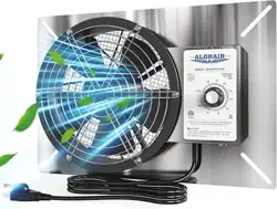
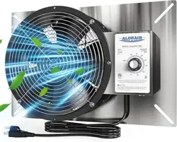
AIRTITAN T3
AIRTITAN T7
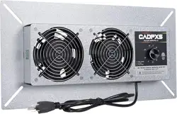
AIRTITAN T8
AIRTITAN T8-N
MODEL
AC-ATT3
AC-ATT7
AC-ATT8
AC-ATT8-N
UPC-A
00819137020467
00819137020474
00819137020481
00819137020498
MANUAL CODE AT2010X2

5
MANUAL INDEX
Manual Index .................................................................................
Key Features .................................................................................
Product Contents ...........................................................................
Mounting ........................................................................................
Powering ........................................................................................
Programming .................................................................................
FAQ ................................................................................................
Other AC Infinity Products .............................................................
Warranty ........................................................................................
Page 5
Page 6
Page 7
Page 8
Page 10
Page 12
Page 20
Page 22
Page 23
6
KEY FEATURES
INGRESS PROTECTION
Fans are sealed to be
dust proof and high water
resistance. Can receive water
splashes and high pressure
water jets.
HEAVY DUTY BUILD
The fan system features a
galvanized steel or aluminum
mounting frame with fan
guards. Fans are enclosed in
steel or plastic.
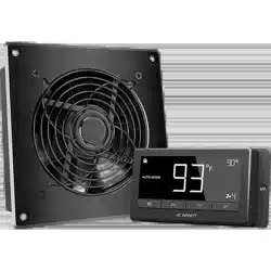
SMART CONTROLLER
Digital controller can be set
to trigger fans at high and low
temperature and humidity.
Features alarms and fan
speed control.
THERMAL PROBE
The corded precision sensor
probe constructed of stainless
steel ensures an accurate
temperature and humidity
reading.
QUIET PWM MOTOR
PWM-controlled motor
features precise speed
control, reduced rotor noise,
and runs on energy efficient
DC voltage.
DUAL BALL BEARINGS
Each fan contains long-life
ball bearings rated at 67,000
hours. This bearing system
enables fans to be mounted in
any direction.
7
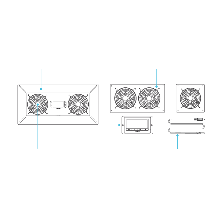
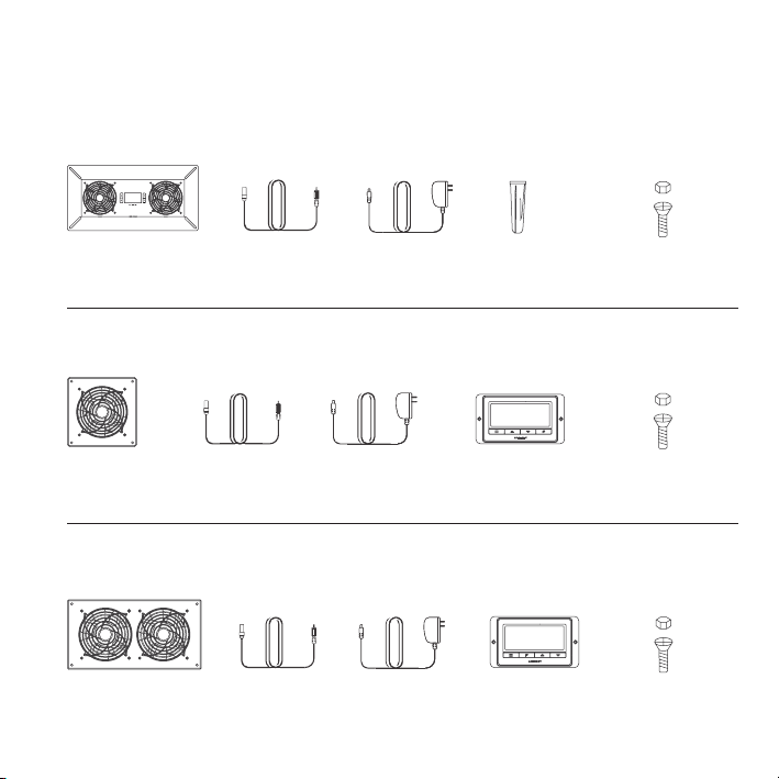
PRODUCT CONTENTS
AIRTITAN T8
AIRTITAN T8-N
AIRTITAN T3
AIRTITAN T7
AC-ATT8
AC-ATT8-N
AC-ATT3
AC-ATT7
THERMAL
PROBE (x1)
THERMAL
PROBE (x1)
POWER
ADAPTER (x1)
POWER
ADAPTER (x1)
FAN
SYSTEM (x1)
FAN
SYSTEM (x1)
UNIVERSAL
CONTROLLER (x1)
FAN
SYSTEM (x1)
WALL
ANCHORS (x4)
THERMAL
PROBE (x1)
POWER
ADAPTER (x1)
MACHINE
SCREWS (x4)
MACHINE
SCREWS (x4)
MACHINE
SCREWS (x4)
UNIVERSAL
CONTROLLER (x1)
8
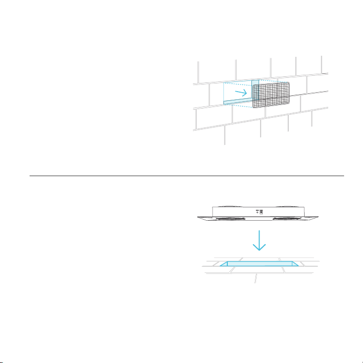
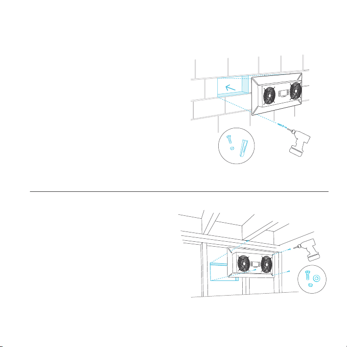
MOUNTING
STEP 1
Remove any existing grilles, vents, or covers
on ventilation opening where you wish to install
the fan unit.
STEP 2
Position the fan unit over the ventilation
opening. Depending on the model, the unit may
be facing towards or away from the wall. Please
be sure to check the airflow direction prior to
installation.
9
MOUNTING
STEP 3 (Wall and Surface Mounting)
If installing the unit onto a cabinet, wall, wood
header, rim joist, or mesh on an existing crawl
space vent, please use the unit or plastic
template to determine the mounting location.
Secure the mounting frame onto the surface
with the included wood screws. If using a
machine screw with nuts, you may need to drill
a hole. Note that models T8 and T8-N do not
include a plastic template.
STEP 3 (Foundation Block Mounting)
To install the unit onto a foundation brick or
block, mark the mounting hole locations using
the four corners of the metal face plate. Then
drill 5/16" holes with a drill bit. Install wall
anchors into openings and secure the unit into
the wall with four screws. Note that the models
T3 and T7 are designed for cabinet and wall
mounting, and do not include wall anchors and
larger type screws.
AIRTITAN T8, T8N Illustration shown above.
AIRTITAN T8, T8N Illustration shown above.
10
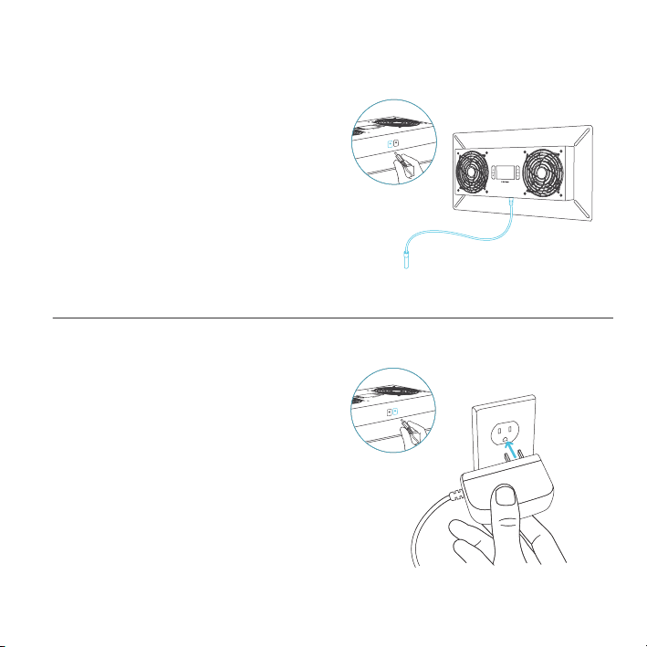
POWERING
STEP 1
To set up temperature monitoring, plug the
male connector of the thermal probe into the
designated probe port located at the bottom
side of the fan unit.
STEP 2
To power the unit plug in the power, plug the
male connector of the corded power adapter
into the designated power port located at
the bottom side of the fan unit. Then plug the
adapter head into an outlet.
AIRTITAN T8 T8-N
11
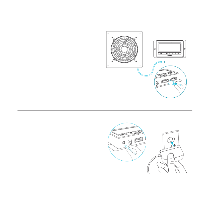
POWERING
STEP 2
To power the unit plug in the power, plug the
male connector of the corded power adapter
into the designated power port located at the
bottom side of the controller. Then plug the
adapter head into an outlet.
STEP 1
Plug the fan's male molex connector into one
of the two designated probe ports located at
the bottom side of the controller.
AIRTITAN T3 T7
12
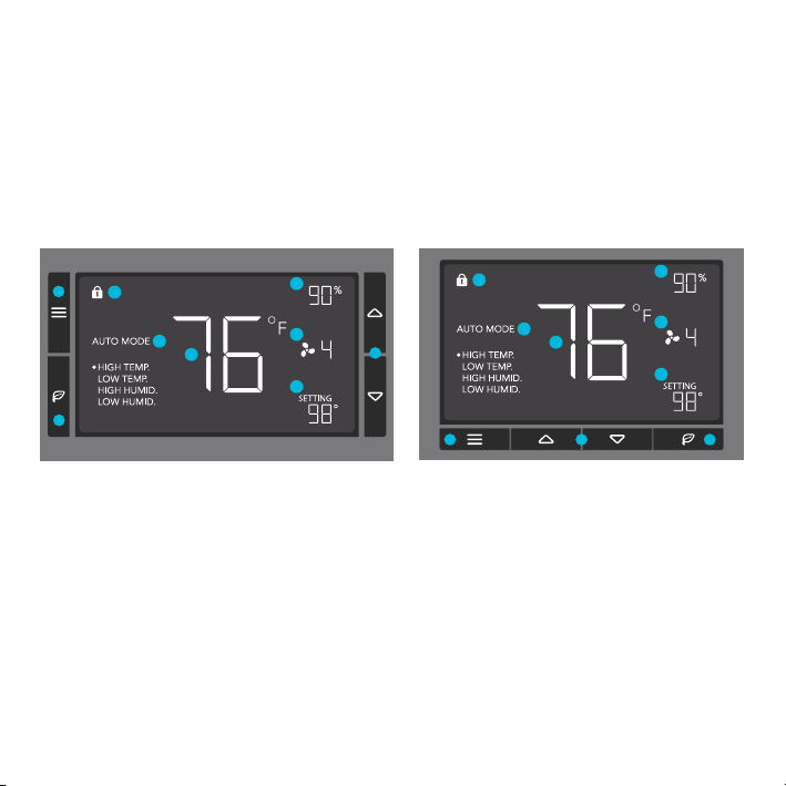
PROGRAMMING
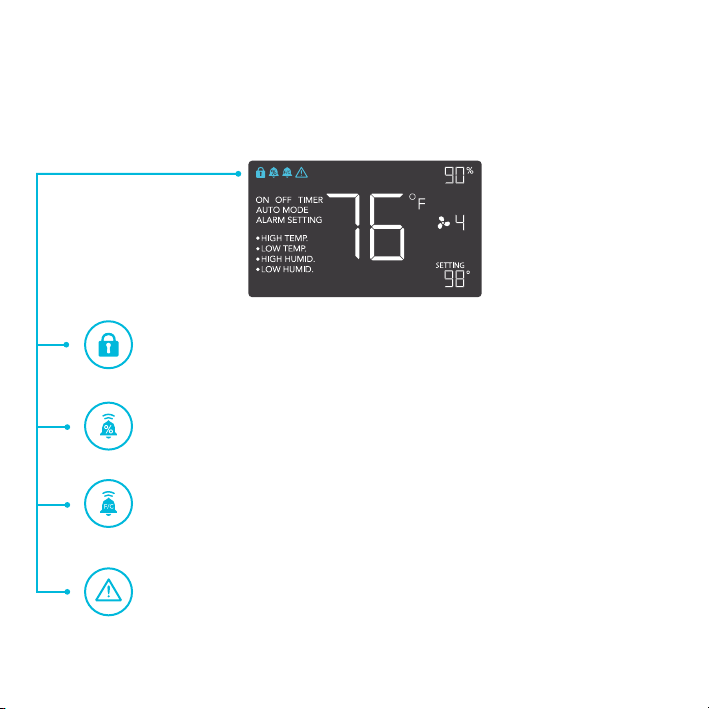
1. MODE BUTTON
This button cycles through
each of the controller's
modes: ON, OFF, TIMER,
AUTO (4 triggers), and
ALARM (4 settings).
4. PROBE TEMP.
Displays the current tempera-
ture that the corded sensor
probe is measuring. Shows
“- -” if no probe is plugged in.
8. FAN SPEED
Displays the current speed
the fan is running at, or what
speed it should be running at
if no fans are plugged in.
6. ALERT ICONS
This area displays the alerts
and statuses from the
controller including alarms
and screen lock.
9. SETTING
Displays the value you
have set for the current
mode. Press the up or
down button to change.
7. PROBE HUMIDITY
Displays the current humidity
that the corded sensor probe
is measuring. Shows “- -” if
no probe is plugged in.
5. CONTROLLER MODE
This area displays the mode
that the controller is currently
in. Press the Mode Button to
cycle through the modes.
3. LEAF BUTTON
This turns the display off
while programs run in the
background. Hold for two
seconds to lock or unlock
the display.
2. UP / DOWN BUTTON
The up and down buttons
adjusts the settings of the
mode that you are in. Up
button increases and
down button decreases.
1
4
7
8
9
6
5
2
3
(AIRTITAN T8, T8N Screen Display)
1 2 3
4
7
8
9
6
5
(AIRTITAN T3, T7 Screen Display)
13
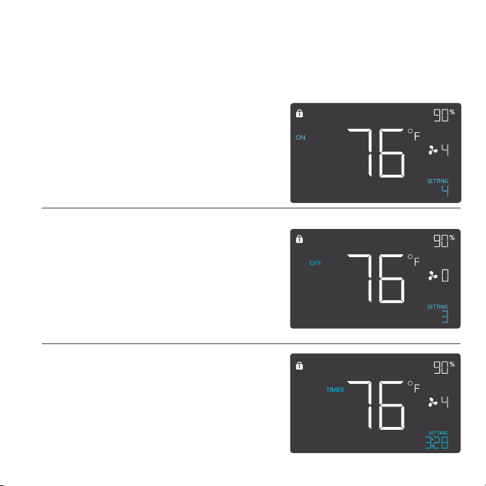
ON MODE
In this mode, the fans will run continuously
regardless of temperature or humidity. The
speed set in this mode will be the max speed
the fans can reach in AUTO Mode.
OFF MODE
In this mode, the fans will not run regardless
of temperature or humidity. While in this mode,
pressing the up or down button will change the
display’s brightness. There are four settings for
brightness, (Setting:1/2/3/A3). On setting A3,
if the device is left unattended for 30 seconds,
the display will automatically dim its brightness
back to setting 1. Holding up or down button
will change the display’s units F or C.
PROGRAMMING
MODE SETTING
Press the Mode button to cycle through the controller’s available programming modes and settings:
ON Mode, OFF Mode, TIMER Mode, AUTO Mode (4 triggers), ALARM Settings (4 settings).
TIMER MODE
In this mode, press the up or down button to set
a time for the timer. The fans will run at the speed
set in ON Mode until the timer’s clock runs out,
in which the fans will stop running. The clock will
begin counting down if no buttons are pressed
for 3 seconds. Leaving the timer mode while the
countdown is running will pause the clock until you
return to this mode.
14
PROGRAMMING
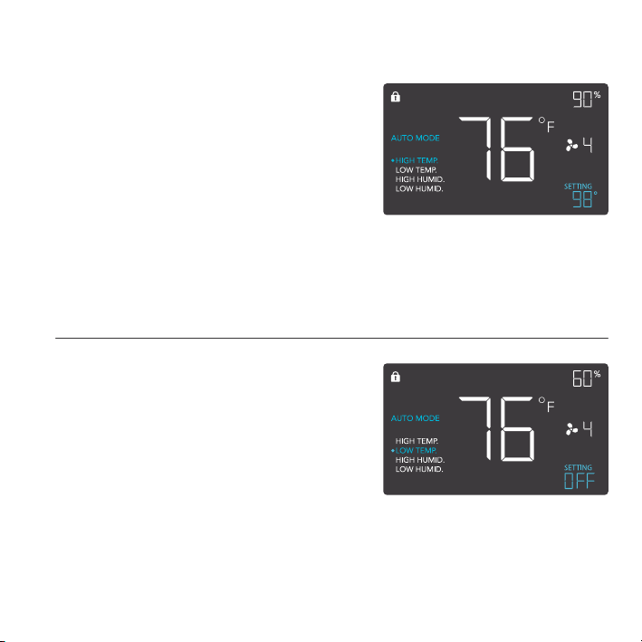
AUTO MODE: HIGH TEMP.
In this mode, press the up or down button to set a
high temperature trigger. The fans will activate if the
probe’s measured temperature exceeds the tem-
perature you have set in this mode. The activated
fans will slowly increase in speed until it reaches
the speed set in ON Mode. Whenever the measured
temperature falls below your set temperature, the
fans will slowly decrease in speed until the fans
stop. You may also hold the up and down button
simultaneously to turn off this trigger, in which the
digits under settings will show OFF for off. Note that
this trigger can activate to run as long as you are in
AUTO Mode, even if you are in setting up the other
AUTO Mode triggers.
AUTO MODE: LOW TEMP.
In this mode, press the up or down button to set
a low temperature trigger. The fans will activate
if the probe’s measured temperature falls below
the temperature you have set in this mode. The
activated fans will slowly increase in speed until
it reaches the speed set in ON Mode. Whenever
the measured temperature rises above your set
temperature, the fans will slowly decrease in speed
until the fans stop. You may also hold the up and
down button simultaneously to turn off this trigger, in
which the digits under settings will show OFF for off.
Note that this trigger can activate to run as long as
you are in AUTO Mode, even if you are in setting up
the other AUTO Mode triggers.
15
PROGRAMMING
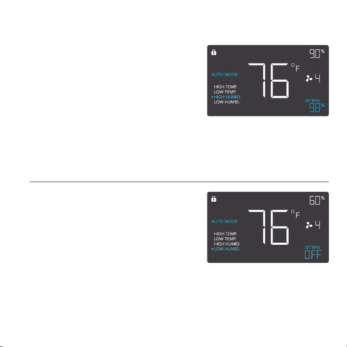
AUTO MODE: HIGH HUMID.
In this mode, press the up or down button to set a
high humidity trigger. The fans will activate if the
probe’s measured humidity exceeds the humidity
you have set in this mode. The activated fans will
slowly increase in speed until it reaches the speed
set in ON Mode. Whenever the measured humidity
falls below your set humidity, the fans will slowly
decrease in speed until the fans stop. You may also
hold the up and down button simultaneously to turn
off this trigger, in which the digits under settings
will show OFF for off. Note that this trigger can
activate to run as long as you are in AUTO Mode,
even if you are in setting up the other AUTO Mode
triggers.
AUTO MODE: LOW HUMID.
In this mode, press the up or down button to set
a low humidity trigger. The fans will activate if the
probe’s measured humidity falls below the humidity
you have set in this mode. The activated fans
will slowly increase in speed until it reaches the
speed set in ON Mode. Whenever the measured
humidity rises above your set temperature, the
fans will slowly decrease in speed until the fans
stop. You may also hold the up and down button
simultaneously to turn off this trigger, in which the
digits under settings will show OFF for off. Note
that this trigger can activate to run as long as you
are in AUTO Mode, even if you are in setting up the
other AUTO Mode triggers.
16
PROGRAMMING
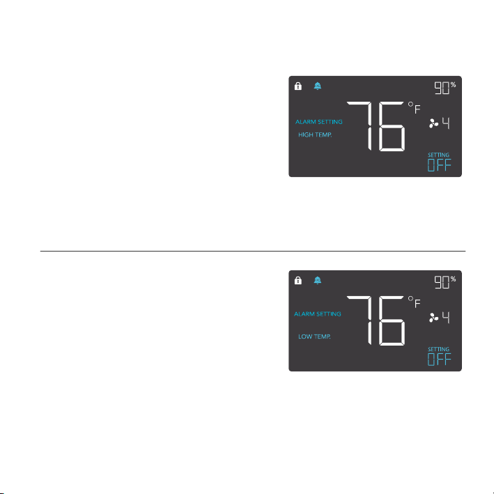
ALARM SETTING: HIGH TEMP.
In this settings mode, press the up and down
button to set a high temperature alarm. The
alarm will activate if the probe’s measured
temperature exceeds the temperature you have
set in this mode. When the alarm triggers, the
fan will start spinning gradually to max speed
regardless of your other settings. You may also
hold the up and down button simultaneously
to turn off this alarm, in which the digits under
settings will show OFF. You will need to be in
AUTO, ON, or TIMER mode for this alarm to be
able to activate.
ALARM SETTING: LOW TEMP.
In this settings mode, press the up and down
button to set a low temperature alarm. The
alarm will activate if the probe’s measured
temperature falls below the temperature you
have set in this mode. When the alarm triggers,
the fan will start spinning gradually to max
speed regardless of your other settings. You
may also hold the up and down button simulta-
neously to turn off this alarm, in which the digits
under settings will show OFF. You will need to
be in AUTO, ON, or TIMER mode for this alarm
to be able to activate.
17
PROGRAMMING
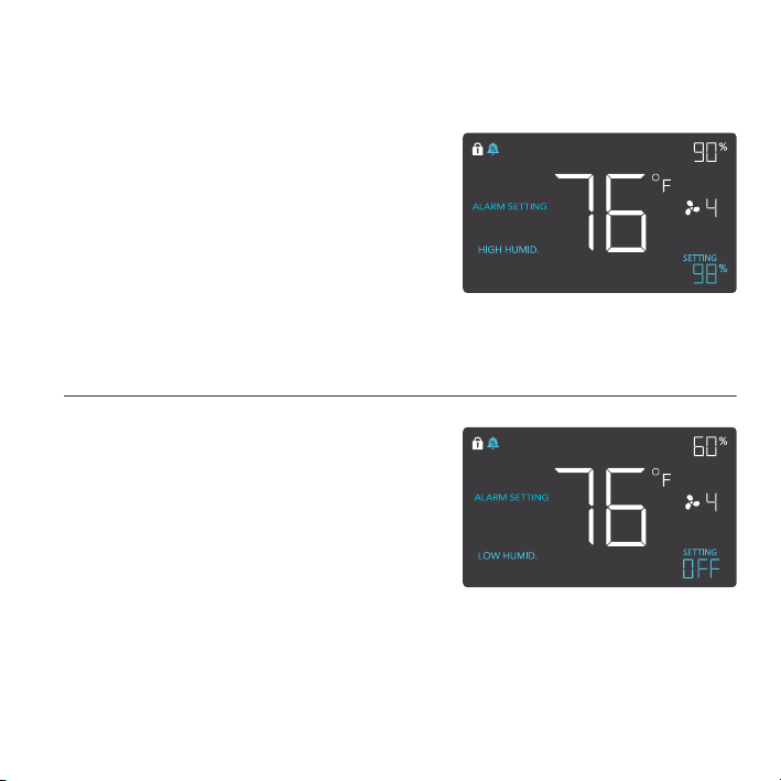
ALARM SETTING: HIGH HUMID.
In this settings mode, press the up and down
button to set a high humidity alarm. The alarm
will activate if the probe’s measured humidity
exceeds the humidity you have set in this
mode. When the alarm triggers, the fan will
start spinning gradually to max speed regard-
less of your other settings. You may also hold
the up and down button simultaneously to turn
off this alarm, in which the digits under settings
will show OFF. You will need to be in AUTO,
ON, or TIMER mode for this alarm to be able
to activate.
ALARM SETTING: LOW HUMID.
In this settings mode, press the up and down
button to set a low humidity alarm. The alarm
will activate if the probe’s measured tempera-
ture falls below the temperature you have set
in this mode. When the alarm triggers, the
fan will start spinning gradually to max speed
regardless of your other settings. You may also
hold the up and down button simultaneously
to turn off this alarm, in which the digits under
settings will show OFF. You will need to be in
AUTO, ON, or TIMER mode for this alarm to be
able to activate.

18
PROGRAMMING
DISPLAY BRIGHTNESS
To adjust the brightness of the display, please set the controller to OFF Mode, then press the up or
down button to increase or decrease the brightness level. Four brightness settings are available.
FAHRENHEIT OR CELSIUS
To change to displayed units between Fahrenheit and Celsius, please set the controller to OFF
Mode, then hold the up button for Fahrenheit (°F) or hold the down button for Celsius (°C).
ECO-MODE
The controller can be put into ECO display in which the screen will be turned off but all programs,
settings, and alarms will be running in the background. This can be done by pressing the LEAF
button. You may also do this while the controller is locked. To exit ECO display, simply press any
buttons.
TEMPERATURE CALIBRATION
To adjust the temperature that the probe sensor is measuring, please press the MODE and UP
button simultaneously. This can be done while the controller is any mode or setting. The calibration
cycle ranges from -8°F to 8°F (or -4°C to 4°C) and will be applied to the probe sensor’s measure-
ments.
HUMIDITY CALIBRATION
To adjust the humidity that the probe sensor is measuring, please press the MODE and DOWN
button simultaneously. This can be done while the controller is any mode or setting. The calibration
cycle ranges from -8% to 8% and will be applied to the probe sensor’s measurements.
CONTROLLER LOCK
To lock the controller to prevent settings to be changed accidently, hold the LEAF button for two
or more seconds. While the display is locked, you will not be able to switch modes or changes any
settings. You will only be able to put the controller in ECO display by pressing the LEAF button.
Holding the LEAF button for two or more seconds will unlock the controller.
19
PROGRAMMING
CHECK FAN ALERT
This icon will flash when the fan’s sensor detects interference to its operation.
Please check the fan for possible issues. If the fan is rotating, it may just be static
pressure resistance and operating as intended. If the fan is not rotating, please
see the warranty page for replacement information. (This feature is only available
on certain model.)
TEMPERATURE ALARM ALERT
This icon will flash when the high or low temperature alarm that you have set has
been triggered.
HUMIDITY ALARM ALERT
This icon will flash when the high or low humidity alarm that you have set has been
triggered.
DISPLAY LOCK ALERT
This icon is visible when the controller has been locked. The icon will flash to alert
you that the controller is locked if you try to change the mode or settings.
ALERT ICONS
On the top left of the display is the alert icon section. Icons may flash when the controller wishes to
alert you that a particular function or alarm is being triggered.

20
AIRTITAN FAQ
Q: Can I mount this crawlspace fan vertically?
A: Yes. The AIRTITAN can be mounted in any orientation, including vertically.
Q: Can I splice the cables to extend them or use my own probe?
A: We do not recommend hardwiring or splicing our fan's power wires. Such modifications may
compromise electrical safety and will void this product's warranty.
Q: How do I reverse the airflow of my crawlspace fan?
A: To flip the fan blades, unscrew the bolts from the steel plate and the body. Flip the fans within
the body and screw the bolts back in.
Q: How far can I mount the controller from the fan?
A: The fan to controller cable is six feet long, which is the distance you can mount the controller
from the fan.
Q: Does the controller retain its settings after power is shut off?
A: Yes. If the controller's power is cut off and is powered on afterwards, your settings will remain.
Q: What connector does the controller use?
A: This fan's controller uses a 4-pin molex cord to connect with the fan.

21
AIRTITAN FAQ
Q: Does this fan include grilles for outside installation or duct tubes for wall installation?
A: This product does not come included with ducting or grilles as accessories.
Q: Is this fan waterproof?
A: The AIRTITAN is IP44 rated for resistance against splashing water.
Q: Will this fan help with Radon mitigation?
A: Yes. The AIRTITAN will ventilate your crawlspace to exhaust radon gas emitting from soil.
Q: Do I need to use both an intake and an exhaust model?
A: In most cases, you will at least need to use an exhaust fan for crawlspace applications. Intake
fans are optional.
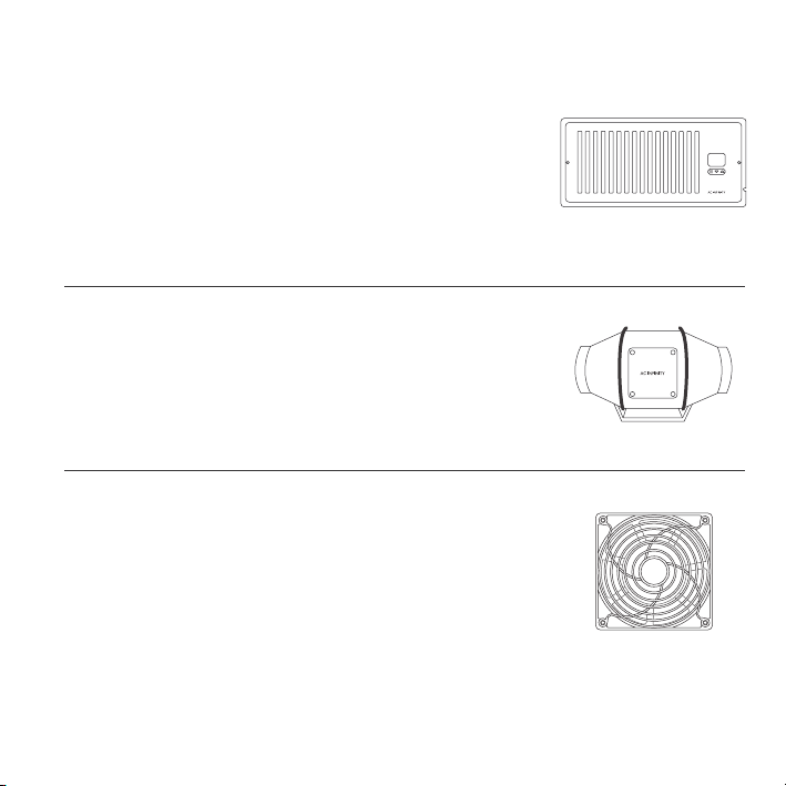
AC INFINITY PRODUCTS
Register Booster Fans
The AIRTAP series is a line of register booster fans designed to
quietly increase airflow coming from your central heat and air
conditioning systems, increasing comfort for your home. Features a
thermal controller with intelligent programming that will automatically
adjust airflow strength in response to heating and cooling
temperatures you have set.
Duct Fans
The CLOUDLINE series is a line of duct fans designed to quietly ven-
tilate AV rooms and closets, as well as various DIY air circulation and
exhaust projects. Features a thermal controller with intelligent pro-
gramming that will automatically adjust duct fan speeds in response
to changing temperatures.
Project Muffin Fans
The AXIAL series fan kit is designed for various DIY projects that
requires cooling or ventilation; or as a replacement fan for many prod-
ucts on the market. Each fan kit includes fan guards and everything
needed to mount the unit onto a wall and power it through a wall
outlet. S-series models include a speed controller.
Discover the latest innovations in cooling and ventilation at acinfinity.com

COPYRIGHT © 2021 AC INFINITY INC. ALL RIGHTS RESERVED
No part of the materials including graphics or logos available in this booklet may be copied,
photocopied, reproduced, translated or reduced to any electronic medium or machine
readable form, in whole or in part, without specific permission from AC Infinity Inc.
WARRANTY
If you have any issues with this product, contact us and we’ll
happily resolve your problem or issue a full refund!
This warranty program is our commitment to you, the product sold by AC Infinity will be free from
defects in manufacturing for a period of two years from the date of purchase. If a product is found
to have a defect in material or workmanship, we will take the appropriate actions defined in this
warranty to resolve any issues.
The warranty program applies to any order, purchase, receipt, or use of any products sold by AC
Infinity or our authorized dealerships. The program covers products that have become defective,
malfunctioned, or expressively if the product becomes unusable. The warranty program goes into
effect on the date of purchase. The program will expire two years from the date of purchase. If your
product becomes defective during that period, AC Infinity will replace your product with a new one
or issue you a full refund.
The warranty program does not cover abuse or misuse. This includes physical damage,
submersion of the product in water, incorrect Installation such as wrong voltage input, and misuse
for any reason other than intended purposes. AC Infinity is not responsible for consequential loss
or incidental damages of any nature caused by the product. We will not warrant damage from
normal wear such as scratches and dings.
For more information about our dealers and distributors, please contact our customer service at
support@acinfinity.com or (626) 923-6399 Monday to Friday (9:00 am to 5:00 pm PST).

www.acinnity.com