Loading ...
Loading ...
3
Operating Instructions and Parts Manual 24338
4/18
2018 OEMTOOLS
™
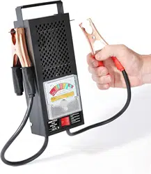
100A BATTERY TESTER
WARNING: ALWAYS wear eye protection and protective
clothing when working with or in the vicinity of a lead-acid
battery. It is recommended that you have fresh water, soap
and baking soda in the immediate vicinity of the workspace.
If battery acid contacts your eyes, skin or clothing,
wash immediately with water and soap; contact medical
professionals. Neutralize any lead acid spills with baking
soda prior to clean-up.
TESTING PREPARATION INSTRUCTIONS
WARNING: To prevent overheating, allow the tester to
cool for 5 minutes between tests.
NOTE: This product does not require assembly.
NOTE: You may notice a slight burning smell during the first
few uses of this product. This is normal and will fade.
1. Turn the ignition OFF. Turn OFF all accessories that may
place load on battery.
2. Clean the battery terminals.
3. Clip the Red Clamp to the Positive (+) battery terminal.
4. Clip the Black Clamp to the Negative (-) battery terminal.
6V BATTERY TESTING INSTRUCTIONS
1. After the proper preparation steps have been taken, read
the meter and confirm battery voltage is in the green “OK”
area. See image of meter below.
2. Press and hold the load switch ON for a maximum of 10
seconds. Read the meter while the load switch is ON. The
needle should remain in the green area.
12V BATTERY TESTING INSTRUCTIONS
1. Check the Cold Cranking Amps (CCA) of the battery being
tested.
2. Connect the tester as described in the Testing Preparation
Instructions.
3. Press and hold the load switch ON for a maximum of 10
seconds. Read the meter while the load switch is ON.
Refer to Battery Analysis Table in this manual or on the
back of the unit.
BATTERY ANALYSIS TABLE
TESTING THE CHARGING SYSTEM
WARNING: Be cautious of moving parts while the
engine is running.
1. Connect the tester as described in the Testing Preparation
Instructions.
2. Turn off all lights and electrical accessories. Run the
engine at 1,200 to 1,500 RPM.
NOTE: DO NOT press the load switch.
3. Read the meter voltage. Meter should be within the green
“OK” band.
4. Turn on the high beams and turn the A/C blower on high.
Meter should remain within the green “OK” band.
5. If the meter does not read within the green “OK” band, the
charging system is not operating correctly.
STARTER MOTOR TEST
NOTE: The engine must be at normal operating temperature
to perform this test.
1. Perform the battery load test; if the battery is in weak or
bad condition, this test cannot be performed. Record the
exact voltage of the load test.
2. Determine the minimum cranking voltage using the voltage
recorded in step 1.
Starter Test Voltage
LOAD VOLTAGE 10.2 10.4 10.6 10.8 11.0 11.2 11.4
MINIMUM CRANKING
VOLTAGE
7.7 8.2 8.7 9.2 9.7 10.2 10.6
NOTE: If possible, disable the vehicle’s ignition system. The
starter motor test is most accurate if the starter cranks for
2-5 seconds.
3. Crank the engine and record the voltage reading.
4. If the cranking voltage is below the minimum cranking
shown in the Start Test Voltage Table, the starter current
draw is excessive. This may be due to bad connections or
a failing starter motor.
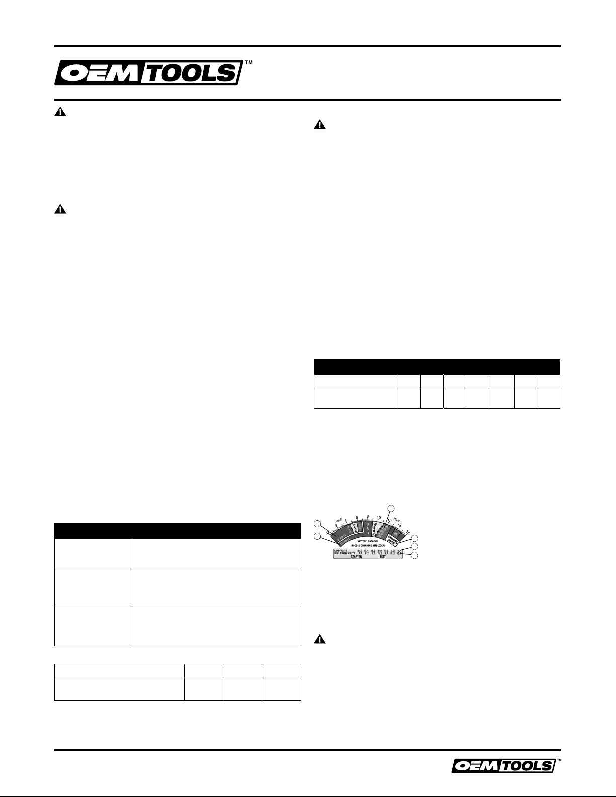
METER
PRODUCT STORAGE
Always store the battery tester in a well-protected area where
it will not be exposed to inclement weather, corrosive vapors,
abrasive dust, fire, or any other harmful elements.
PRODUCT MAINTENANCE
WARNING: DO NOT attempt to repair or disassemble
the tester. Contact customer service or a qualified service
professional.
1. Disconnect from battery and allow the unit to cool.
2. Use a clean, dry cloth to wipe the outer surfaces of the
battery tester clean.
DISPOSAL
At the end of the useful life of the OEMTOOLS
™
24338 100A
Battery Tester, dispose of the components in accordance
with all federal, state and local regulations.
Indication Battery Condition
GREEN OK - Battery may or may not be fully charged.
Check the specific gravity of the battery to
determine charge level, recharge if necessary.
YELLOW / RED
(STEADY NEEDLE)
WEAK - Battery capacity is not satisfactory.
Check the specific gravity of the battery. If full
charge cannot be reached after attempting
recharge, the battery should be replaced.
YELLOW / RED
(FALLING NEEDLE)
WEAK OR DEFECTIVE - Release the load
switch. If immediate voltage recovery (to
12V or above) is noted, the battery may be
defective. Check the specific gravity.
BATTERY TEMPERATURE +20°F 0°F -20°F
DECREASE BATTERY RATING
BY (CRANKING AMPS)
200 400 600
TEMPERATURE COMPENSATION
1. Range for 6 Volt battery load testing
2. Range for 12 Volt battery load testing
3. Cold cranking amps range
4. Charging system test range
5. Voltage scale
6. Starter voltage test table
1
3
5
4
6
2
Loading ...