
Installation Instructions
for T
opload Washers
Original Instructions
Keep These Instructions for Futur
e Reference.
(If this machine changes ownership, this manual must accompany machine.)
www.alliancelaundry.com
Part No. 203031R3
January 2017


Table of Contents
Washer Dimensions and Specifications....................................................4
Installation............................................................................................. 5
Before You Start............................................................................................. 5
Supplies..................................................................................................... 5
Order of Installation Steps............................................................................5
Parts Included............................................................................................. 5
Position Washer Near Installation Area............................................................. 5
Remove the Shipping Brace and Shipping Plug................................................. 5
Wipe Out Inside of Washtub............................................................................ 6
Connect Fill Hoses..........................................................................................6
Water Supply Requirements......................................................................... 6
Connecting Hoses....................................................................................... 7
Connect Drain Hose to Drain Receptacle.......................................................... 8
Standpipe Installation.................................................................................. 8
Low Standpipe Installation...........................................................................8
Wall Installation.......................................................................................... 8
Laundry Tub Installation..............................................................................9
Position and Level the Washer......................................................................... 9
Connect the Washer to Electrical Power.......................................................... 10
Electrical Requirements............................................................................. 10
Earth/Ground Instructions.......................................................................... 11
Add Water to the Washer............................................................................... 11
Check Lid Switch..........................................................................................11
Recheck Steps 1-9.........................................................................................11
Installer Checklist.................................................................................12
©
Copyright 2017, Alliance Laundry Systems LLC
All rights reserved. No part of the contents of this book may be reproduced or transmitted in any form or by any means without the expressed
written consent of the publisher.
©
Copyright, Alliance Laundry Systems LLC -
DO NOT COPY or TRANSMIT
3 Part No. 203031R3
Washer Dimensions and Specifications
Maximum spin speed of washer is 710 RPM.
TLW2075N_SVG
JI
H
G
F
E
D
C
B
A
*With leveling legs turned into base.
A 711 mm [28 in.]
B 562 mm [22.13 in.]
C *1346 mm [53 in.]
D *1022 mm [40.25 in.]
E 660 mm [26 in.]
F 10 mm [0.4 in.]
G 651 mm [25.63 in.]
H *737 mm [29 in.]
I *1092 mm [43 in.]
J *914 mm [36 in.]
Washer Dimensions and Specifications
©
Copyright, Alliance Laundry Systems LLC -
DO NOT COPY or TRANSMIT
4 Part No. 203031R3
Installation
Before You Start
Supplies
For most installations, the basic supplies you will need are:
TLW2218N_SVG
3
4
5
6
7
2
1
1. Safety Glasses
2. Wood Block
3. Gloves
4. Wrench
5. Screwdriver
6. Pliers
7. Level
Figure 1
NOTE: If the washer is delivered on a cold day (below
freezing), or is stored in an unheated room or area dur-
ing the cold months, do not attempt to operate it until
the washer has had a chance to warm up.
NOTE: Install dryer before washer. This allows room for
attaching exhaust duct.
NOTE: This appliance is suitable for use in countries
having a warm, damp climate.
Order of Installation Steps
The proper order of steps must be followed to ensure correct in-
stallation. Refer to the list below when installing your unit.
1. Position washer near installation area.
2. Remove the shipping brace and shipping plug.
3. Wipe out the inside of the washtub
4. Connect the fill hoses.
5. Connect the drain hose to the drain receptacle.
6. Position and level the washer.
7. Connect the washer to electrical power.
8. Add water to the washer.
9. Check the lid switch.
10. Recheck steps 1-9.
Parts Included
An accessories bag has been shipped inside your washer. It in-
cludes:
• Two fill hoses with washers and filter screens
• Four rubber feet
• Beaded strap
• Installation Instructions
• User’s Guide
• Installer Checklist
Position Washer Near Installation Area
Remove the Shipping Brace and
Shipping Plug
1. Remove the shipping brace from under the lid.
2. The shipping plug will be released from the base of the wash-
er when removing the cardboard base from the washer. Refer
to Figure 2 .
The shipping brace and plug should be saved and must be rein-
stalled whenever washer is moved or transported to a new loca-
tion. This will prevent damage to washer components.
Do not tilt washer to front or sides when moving.
Refer to the User's Guide for instructions on reinstalling the ship-
ping materials.
Installation
©
Copyright, Alliance Laundry Systems LLC -
DO NOT COPY or TRANSMIT
5 Part No. 203031R3
TLW1975N_SVG
2
1
3
1. Shipping Brace
2. Shipping Plug
3. Cardboard Base
Figure 2
Wipe Out Inside of Washtub
Prior to first wash, use an all purpose cleaner or a detergent
and water solution and a damp cloth to remove shipping dust
from inside of washtub.
TLW2009N_SVG
Figure 3
Connect Fill Hoses
WARNING
Under certain conditions, hydrogen gas may be pro-
duced in a hot water system that has not been used
for two weeks or more. HYDROGEN GAS IS EXPLO-
SIVE. If the hot water system has not been used for
such a period and before using the washer, turn on
all hot water taps and let the water flow from each for
several minutes. This will release any accumulated
hydrogen gas. The gas is flammable. Do not smoke
or use an open flame during this time.
W029
Water Supply Requirements
Water supply taps must fit standard 19 mm [3/4 inch] female gar-
den hose couplings. DO NOT USE SLIP-ON OR CLAMP-ON
CONNECTIONS.
NOTE: Water supply taps should be readily accessible
to permit turning them off when washer is not being
used.
Recommended cold water temperature is 10° to 24° Celsius [50°
to 75° Fahrenheit]. Recommended maximum hot water tempera-
ture is 51° Celsius [125° Fahrenheit]. Warm water is a mixture of
hot and cold water. Warm water temperature is dependent upon
the water temperature and the pressure of both the hot and cold
water supply lines.
WARNING
To prevent personal injury, avoid contact with inlet
water temperatures higher than 51° Celsius [125°
Fahrenheit] and hot surfaces.
W748
Water pressure must be a minimum of 138 to a maximum of 827
kPa [minimum of 20 to a maximum of 120 pounds per square
inch] static pressure measured at the tap.
NOTE: Water pressure under 138 kPa [20 pounds per
square inch] will cause an extended fill time in the
washer.
The appliance is to be connected to the water mains using new
hose-sets and the old hose-sets should not be reused.
Turn on the water supply taps and flush the lines for approxi-
mately two minutes to remove any foreign materials that could
clog the screens in the water mixing valve. This is especially im-
portant when installing your washer in a newly constructed or
renovated building. Build-up may have occurred during construc-
tion.
Installation
©
Copyright, Alliance Laundry Systems LLC -
DO NOT COPY or TRANSMIT
6 Part No. 203031R3
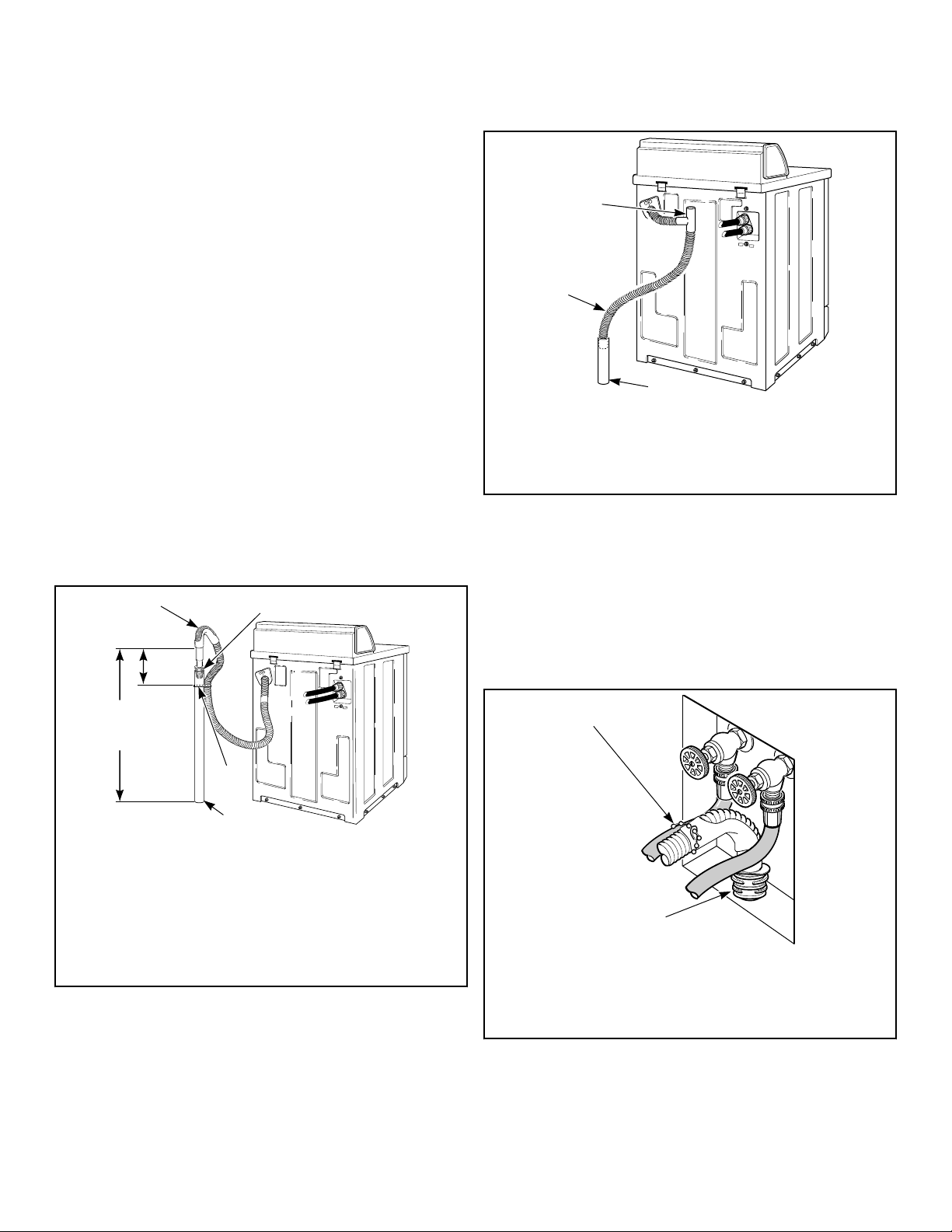
Connecting Hoses
To comply with Australian water regulations and Australian
standard AS/NZS3500.1, an approved dual check valve backflow
prevention device with the watermark must be fitted at the point
of connection(s) between the supply and the fitting. Refer to Fig-
ure 5 .
Figure 4
Connections should be supplied by a hot and a cold water line per
national and local codes and in accordance with AS/NZS 3500.1.
1. Insert rubber washers and filter screens (from accessories
bag) in water fill hose couplings (two hoses supplied with
washer). The filter screen must be facing outward.
NOTE:
If using black rubber hoses with black and brass cou-
plings: Insert filter screens into the BLACK colored
hose couplings (BSPP thread). Insert rubber washers
into the brass colored hose couplings (Garden Hose
Thread [GHT]).
If using gray braided hoses with silver hose couplings
(one with hex nut): Insert filter screens into the hex nut
shaped hose couplings (BSPP thread). Insert rubber
washers into the knurled, round shaped hose cou-
plings (GHT).
2. Connect fill hose couplings with filter screens to water supply
taps.
3. Connect the other hose couplings to the hot and cold valve
connections at the rear of the washer.
NOTE:
If using black rubber hoses with black and brass cou-
plings: Connect the BLACK colored hose coupling
(BSPP thread) end of the fill hoses (with filter screens)
to the water supply taps. Then connect end of hoses
with the brass colored hose couplings (GHT) to the hot
and cold water mixing valve connections at rear of
washer.
If using gray braided hoses with silver hose couplings
(one with hex nut): Connect the hex nut shaped hose
couplings (BSPP thread, with filter screens) to the wa-
ter supply taps. Then connect couplings with knurled,
round shaped couplings (GHT) to the hot and cold wa-
ter mixing valve connections at rear of washer.
4. Make sure the hose from the hot water tap goes to the water
mixing valve marked “H” and the hose from the cold tap goes
to the valve marked “C”.
5. Thread hose couplings onto valve connections finger tight.
Then turn 1/4 turn with pliers.
IMPORTANT: DO NOT cross thread or overtighten
couplings. This will cause them to leak.
6. Turn water on and check for leaks.
7. If leaks are found, retighten the hose couplings.
8. Continue tightening and rechecking until no leaks are found.
COLD
HOT
TLW2265N_SVG
C
H
9
3
7
6
5
1
4
8
2
1. Tap
2. Fill Hoses
3. Install this end of hose to valve connections at rear of
washer
4. Plain Rubber Washer
5. Cold Water Connection
6. Hot Water Connection
7. Install this end of hose to water supply tap (Black colored
or hex nut shaped coupling for BSPP thread)
8. Filter Screens
9. Dual Check Valves
Figure 5
IMPORTANT:
Hoses and other natural rubber parts deteriorate after
extended use. Hoses may develop cracks, blisters or
material wear from the temperature and constant high
pressure they are subjected to.
All hoses should be checked on a monthly basis for
any visible signs of deterioration. Any hose showing
the signs of deterioration listed above should be re-
placed immediately. All hoses should be replaced ev-
ery five years.
IMPORTANT: Turn off water supply taps after check-out
and demonstration. Owner should turn off water supply
whenever there will be an extended period of non-use.
Installation
©
Copyright, Alliance Laundry Systems LLC -
DO NOT COPY or TRANSMIT
7 Part No. 203031R3
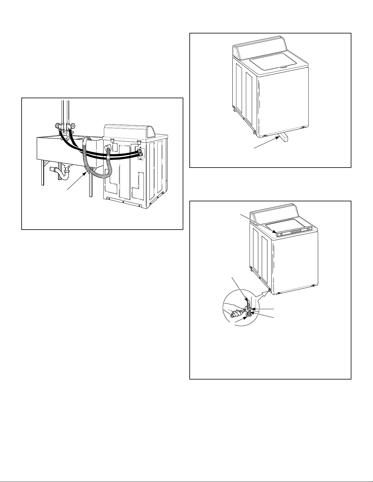
Connect Drain Hose to Drain
Receptacle
1. Remove the drain hose from its shipping position on the rear
of the washer by unhooking the hose from the retainer clamp.
2. Install the drain hose into the drain receptacle (standpipe, wall
or laundry tub) following the instructions below.
NOTE: Drain receptacle must be capable of handling
a minimum of 32 mm [1-1/4 inch] outside diameter
drain hose.
Standpipe Installation
1. Check standpipe height. The recommended height for the
standpipe is 914 mm [36 inches]. Standpipes higher than 1220
mm [4 feet] are not recommended.
2. Place the adapter into the standpipe.
IMPORTANT: To prevent siphoning, do not place
any ribbed portion of the drain hose into the stand-
pipe.
3. Remove the beaded strap from accessories bag and place
around standpipe and drain hose, approximately 300 mm [12
inches] down from the top of pipe. Refer to Figure 6 .
4. Tighten strap to hold hose to standpipe. This will prevent the
drain hose from dislodging from drain receptacle during use.
TLW2220N_SVG
5
6
4
3
2
1
1. Ribbed Portion of Drain Hose
2. Standpipe Adapter
3. Beaded Strap
4. Standpipe - 51mm [2 in.] or 40 mm [1-1/2 in.] Diameter
5. 914 mm [36 in.] Recommended Height
6. 305 mm [12 in.]
Figure 6
Low Standpipe Installation
If standpipe is lower than 914 mm [36 inches], you must install
No. 562P3 Siphon Break Kit. Refer to Figure 7 . This kit is avail-
able (as optional equipment at extra cost) through an authorized
dealer or parts distributor. Installation instructions are supplied
with the kit.
TLW2221N_SVG
2
1
3
1. 562P3 Siphon Break Kit
2. Standpipe
3. Drain Hose
Figure 7
Wall Installation
For installations of this type, the drain hose MUST be secured to
one of the fill hoses using the beaded strap from accessories bag.
Refer to Figure 8 .
NOTE: End of drain hose must not be below height of
cabinet top.
W329I_SVG
2
1
1. Beaded Strap (tape if necessary)
2. Standpipe Adapter
Figure 8
Installation
©
Copyright, Alliance Laundry Systems LLC -
DO NOT COPY or TRANSMIT
8 Part No. 203031R3
Laundry Tub Installation
For this type of installation, the drain hose MUST be secured to
the stationary tub to prevent hose from disloding during use. Re-
fer to Figure 9 . Use the beaded strap (supplied in accessories
bag) to secure hose.
We recommend leaving the standpipe adapter on the drain hose
for this type of installation.
TLW2222N_SVG
1
1. Beaded Strap (tape if necessary)
Figure 9
Position and Level the Washer
1. Position washer so it has sufficient clearance for installation
and servicing.
2. Place washer in position on a clean, dry, and reasonably firm
floor. Installing the washer on any type of carpeting is not rec-
ommended.
NOTE: The openings in the base must not be ob-
structed by a carpet.
3. For easier access to leveling legs, prop up washer with a
wooden block.
TLW2252N_SVG
1
1.
Wood Block
Figure 10
4. Place rubber cups (from accessories bag) on all four leveling
legs.
TLW2168N_SVG1
1
2
3
5
4
1. Level
2. Locknut
3. Leveling Leg
4. Rubber Cup
5. Washer Base
Figure 11
5. Place a level on the cabinet top and check if the washer is lev-
el from side to side and front to back.
6. If washer is not level, tilt washer back to access the front lev-
eling legs. Loosen the locknuts and adjust legs by screwing
into or out of washer base.
Installation
©
Copyright, Alliance Laundry Systems LLC -
DO NOT COPY or TRANSMIT
9 Part No. 203031R3
7. Once adjusted, tilt the washer forward on front legs and lower
back down into position to set the rear self-leveling legs.
8. Washer must not rock. When washer is level and does not
rock, tighten locknuts securely against bottom of washer base.
If these locknuts are not tight, washer will not remain station-
ary during operation.
Improper installation or flexing of weak floor will cause exces-
sive vibration.
Do not slide washer across floor once the leveling legs have been
extended, as legs and base could become damaged.
9. Verify that unit does not rock.
Connect the Washer to Electrical Power
This appliance is to be supplied through a residual current device
(RCD) having a rated residual operating current not exceeding 30
mA.
Electrical Requirements
240 Volt/50 Hertz with 3-Prong Earth/Ground Plug
This appliance is to be supplied through a residual current device
(RCD) having a rated residual operating current not exceeding 30
mA.
NOTE: The wiring diagram is located in the control
hood.
WARNING
To reduce the risk of fire, electric shock, serious in-
jury or death, all wiring and earth/ground connec-
tions MUST conform with the latest edition of the
AS/NZS 2040.2:2005 and such local regulations as
might apply. It is the customer’s responsibility to
have the wiring, fuses and circuit breakers installed
by a qualified electrician to make sure adequate elec-
trical power is available to the washer.
W895
When plugging in the washer:
• DO NOT overload circuits.
• DO NOT use an extension cord.
• DO NOT use an adapter.
• DO NOT operate other appliances on the same circuit.
CAUTION
If this appliance is supplied from a cord extension
set or an electrical portable outlet device, the cord
extension set or electrical portable outlet device
must be positioned so that it is not subject to
splashing or ingress of moisture.
W563
WARNING
To reduce the risk of an electric shock or fire, DO
NOT use an extension cord or an adapter to connect
the washer to the electric power source.
W082
The washer is designed to be operated on a separate polarized
three-wire, earth/ground, 240 Volt, 50 Hertz, single-phase electri-
cal circuit protected by a 10 ampere fuse, equivalent fusetron or
circuit breaker.
The 3-prong earth/ground plug on the power cord should be plug-
ged directly into a polarized three-slot receptacle properly instal-
led and connected to a protective earth/ground and rated 240
Volts AC (alternating current) 10 Amps. Refer to Figure 12 to de-
termine correct polarity of the wall receptacle.
Standard 240 Volt, 50 Hertz, 3 Wire Effective Earth/
Ground Circuit
TLW2166N_SVG
2
1
43
3
1. Power Cord
2. Earth/Ground Prong
3. 240 Volt/50 Hertz
4. 0 Volt
Figure 12
Installation
©
Copyright, Alliance Laundry Systems LLC -
DO NOT COPY or TRANSMIT
10 Part No. 203031R3
Earth/Ground Instructions
This appliance must be properly connected to protective earth/
ground. In the event of malfunction or breakdown, the earth/
ground will reduce the risk of electric shock by providing a path
of least resistance for electric current.
The appliance is equipped with a cord having an equipment earth/
ground conductor and a three-prong earth/ground plug. The plug
must be plugged into an appropriate outlet that is properly instal-
led and connected to a protective earth/ground in accordance with
all local codes and ordinances.
WARNING
Improper connection of the equipment earth/ground
conductor can result in a risk of electric shock.
Check with a qualified electrician or service person if
you are in doubt as to whether the unit is properly
connected to a protective earth/ground.
W893
• DO NOT modify the plug provided with the unit – if it will
not fit the outlet, have a proper outlet installed by a qualified
electrician.
• If the laundry room’s electrical supply does not meet the
above specifications and/or if you are not sure the laundry
room has an effective earth/ground, have a qualified electri-
cian or your local electrical utility company check it and cor-
rect any problems.
WARNING
This unit is equipped with a three-prong (earth/
ground) plug for your protection against shock haz-
ard and should be plugged directly into a protective
earth/ ground three-prong receptacle. Do not cut or
remove the earth/ground prong from this plug.
W823
If the supply cord is damaged, it must be replaced by the manu-
facturer, its service agent, or similarly qualified persons in order
to avoid a hazard.
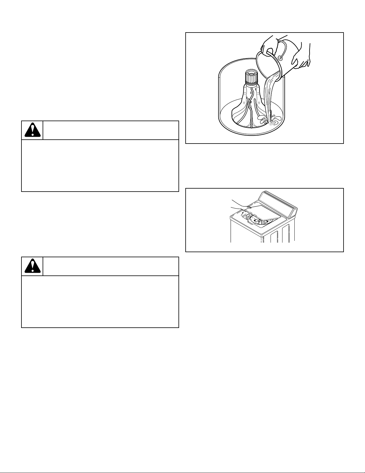
Add Water to the Washer
To prevent damage to pump, do not run washer before adding at
least 0.95 liter [one quart] water to the tub. If the washer is run
before any water is added, the pump seal may overheat, causing
the pump to leak. Once installed, the water retained in the drain
system from the previous cycle will provide sufficient cooling to
prevent pump seal damage.
NOTE: The agitator should not be removed except for
service. The washtub is designed to be self-cleaning.
W391I_SVG
Figure 13
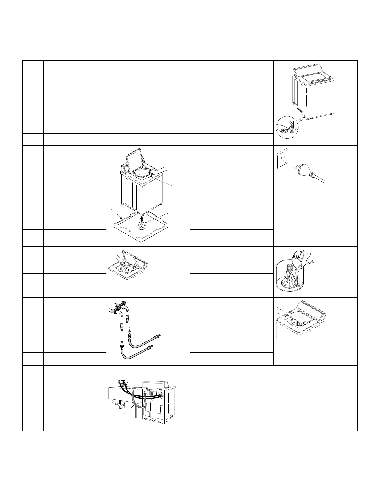
Check Lid Switch
Washer should stop agitating and spinning when lid is opened.
W376I_SVG
Figure 14
Recheck Steps 1-9
1. Refer to Installer Checklist on the back cover of this manual
and make sure that washer is installed correctly.
2. Run washer through one complete cycle to make sure it is op-
erating properly.
Installation
©
Copyright, Alliance Laundry Systems LLC -
DO NOT COPY or TRANSMIT
11 Part No. 203031R3
Installer Checklist
1 Position Washer Near Installation Area. 6 Position and Level
the Washer.
NOTE: Tighten
locknut after final
adjustment.
NOTE: Place rub-
ber feet on all four
leveling legs.
TLW2168N_SVG
CHECK CHECK
2 Remove the Shipping
Brace and Shipping
Plug.
NOTE: Save the
shipping brace and
plug. They must be
reinstalled whenev-
er washer is moved
or transported to a
new location.
TLW1975N_SVG
2
1
3
7 Connect Washer to
Electrical Power
TLW2170N_SVG
CHECK CHECK
3 Wipe Out Inside of
Washtub.
TLW2127N_SVG
8 Add Water to the
Washer to Prevent
Damage to Pump.
W391I_SVG
CHECK CHECK
4 Connect Fill Hoses.
NOTE: Screw black
colored or hex nut
shaped hose cou-
plings onto the wa-
ter taps.
FLW2216N_SVG1
HOT
COLD
9 Check Lid Switch by
Opening Lid During
Agitation Portion of
Wash Cycle.
TLW2128N_SVG
CHECK CHECK
5 Connect Drain Hose to
Drain Receptacle.
W515I_SVG
1
10 Recheck Steps 1-9.
NOTE: Refer to User's Guide for proper opera-
tion.
CHECK CHECK
Installer Checklist
©
Copyright, Alliance Laundry Systems LLC -
DO NOT COPY or TRANSMIT
12 Part No. 203031R3