Loading ...
Loading ...
Loading ...
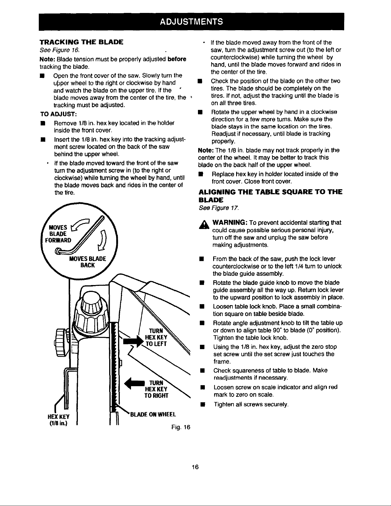
TRACKING THE BLADE
See Figure 16.
Note: Blade tension must be properly adjusted before
tracking the blade.
• Open the front cover of the saw. Slowly turn the
u_per wheel to the right or clockwise by hand
and watch the blade on the upper tire. Ifthe
blade moves away from the center of the tire, the
tracking must be adjusted.
TO ADJUST:
• Remove 1/8 in. hex key located in the holder
inside the front cover.
• Insert the 1/8 in. hex key into the tracking adjust-
ment screw located on the back of the saw
behind the upper wheel.
If the blade moved toward the front of the saw
turn the adjustment screw in (to the right or
clockwise) while turning the wheel by hand, until
the blade moves back and rides in the center of
the tire.
HEXKEY
_ in.)
Fig. 16
If the blade moved away from the front of the
saw, turn the adjustment screw out (to the left or
counterclockwise) while turning the wheel by
hand, until the blade moves forward and rides in
the center of the tire.
• Check the position of the blade on the other two
tires. The blade should be completely on the
tires. If not, adjust the tracking until the blade is
on all three tires.
• Rotate the upper wheel by hand in a clockwise
direction for a few more turns. Make sure the
blade stays in the same location on the tires.
Readjust if necessary, until blade is tracking
properly.
Note: The 1/8 in. blade may not track properly in the
center of the wheel. It may be better to track this
blade on the back half of the upper wheel.
• Replace hex key in holder located inside of the
front cover. Close front cover.
ALIGNING THE TABLE SQUARE TO THE
BLADE
See Figure 17,
,_ WARNING: To prevent accidental starting that
could cause possible serious personal injury,
turn off the saw and unplug the saw before
making adjustments.
• From the back of the saw, push the lock lever
counterclockwise or to the left 1/4 turn to unlock
the blade guide assembly.
• Rotate the blade guide knob to move the blade
guide assembly all the way up. Return lock lever
to the upward position to lock assembly in place.
• Loosen table lock knob. Place a small combina-
tion square on table beside blade.
• Rotate angle adjustment knob to tiltthe table up
or down to align table 90" to blade (0° position).
Tighten the table lock knob.
• Using the 1/8 in. hex key, adjust the zero stop
set screw until the set screw just touches the
frame.
Check squareness of table to blade. Make
readjustments if necessary.
Loosen screw on scale indicator and align red
mark to zero on scale.
Tighten all screws securely.
16
Loading ...
Loading ...
Loading ...