
USER GUIDE & SERVICE MANUAL
5 Class
●
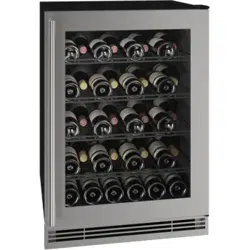
UHWC524
●
24” Wine Captain
®

USER GUIDE
Introduction
u-line.com
WELCOME TO U-LINE
Congratulations on your U-Line purchase. Your product comes from a company with over five decades of premium modular
ice making, refrigeration, and wine preservation experience. U-Line continues to be the American leader, delivering versatility
and flexibility for multiple applications including residential, light commercial, outdoor and marine use. U-Line’s complete
product collection includes Wine Captain
®
Models, Beverage Centers, Clear Ice Machines, Nugget Ice Machines, Crescent Ice
Makers, Glass & Solid Door Refrigerators, Drawer Models, Freezers, Combo
®
Models, and more.
U-Line has captivated those with an appreciation for the finer things with exceptional functionality, style, inspired innovations
and attention to even the smallest details. We are known and respected for our unwavering dedication to product design,
quality and selection. U-Line is headquartered in Milwaukee, Wisconsin and has shipped product to five continents for over
two decades and is proud to have the opportunity to ship to you.
PRODUCT INFORMATION
Looking for additional information on your product? User Guides, Spec Sheets, CAD Drawings, Compliance Documentation,
and Product Warranty information are all available for reference and download at u-line.com.
PROPERTY DAMAGE / INJURY CONCERNS
In the unlikely event property damage or personal injury is suspected related to a U-Line product, please take the following
steps:
1. U-Line Customer Care must be contacted immediately at +1.800.779.2547.
2. Service or repairs performed on the unit without prior written approval from U-Line is not permitted. If the unit has been
altered or repaired in the field without prior written approval from U-Line, claims will not be eligible.
GENERAL INQUIRIES
U-Line Corporation
8900 N. 55th Street
Milwaukee, Wisconsin 53223 USA
Monday - Friday 8:00 am to 4:30 pm CST
T: +1.414.354.0300
F: +1.414.354.7905
Email: sales@u-line.com
u-line.com
SERVICE & PARTS ASSISTANCE
Monday - Friday 8:00 am to 4:30 pm CST
T: +1.800.779.2547
F: +1.414.354.5696
Service Email: onlineservice@u-line.com
Parts Email: onlineparts@u-line.com
CONNECT WITH US
Designed, engineered and assembled in WI, USA
3
USER GUIDE
Integrated Panel Dimensions
u-line.com
Integrated Panel Dimensions
Metric measurements rounded and optimized.
INTEGRATED FRAME
NOTICE
Due to differences in surrounding cabinetry the
panel may not perfectly align with door. The
procedure below is designed to provide a
finished integrated panel that seamlessly
integrates with surrounding cabinetry.
Panel Preparation
A full integrated door panel completely covers the door
frame and provides a built-in appearance.
NOTICE
The door panel must not weigh more than 20 lbs
(10 kg).
It is important to ensure that all drilled holes are
drilled to the correct depth in order to avoid
splits in the wood when hardware is installed.
1. Cut the panels to the dimensions listed in the diagram
below.
2. Optional: Stain or finish panel to desired stain or color.
Be sure to closely follow the instructions provided by
the manufacturer.
3. Optional: Install handles and hardware.
NOTICE
When applying an integrated frame to a unit,
ensure that both sides are finished in order to
prevent warping. In some frame installations,
the panel may be visible through the glass while
the door is open.
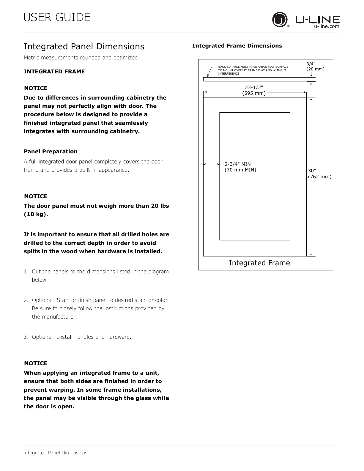
Integrated Frame Dimensions
BACK SURFACE MUST HAVE AMPLE FLAT SURFACE
TO MOUNT OVERLAY FRAME FLAT AND WITHOUT
INTERFERENCE
2-3/4" MIN
(70 mm MIN)
Integrated Frame
3/4"
(20 mm)
23-1/2"
(595 mm)
30"
(762 mm)
4
USER GUIDE
Integrated Panel Dimensions
u-line.com
HANDLELESS INTEGRATED FRAME
The following procedure is designed to provide a finished,
handleless frame for a 24" (600 mm) door that seamlessly
integrates with its surrounding cabinetry.
NOTE: Many cabinet manufacturers provide a ready
solution for a handleless, integrated design that can be
easily applied to your model. Consult your cabinet
manufacturer for applicable design and installation details.
The cabinet manufacturer’s solution to this design and
integration detail will often result in an integrated frame
solution wherein the size of the frame may result in a
height dimension taller than what we specify. This can be
achieved provided the additional height is positioned
above the appliance door.
NOTICE
The integrated frame aligns with the
surrounding cabinetry and, due to differences in
cabinetry, may not align perfectly with the door.
The appliance will need up to 34-1/2" (876 mm)
to the underside of the counter to leave room for
leveling adjustments.
A single prepared frame with insert must not
weigh more than 20 lbs (10 kg).
Integrated Frame Preparation
1. Cut the main panel to the appropriate dimensions
below. For details, see the drawings on the next page.
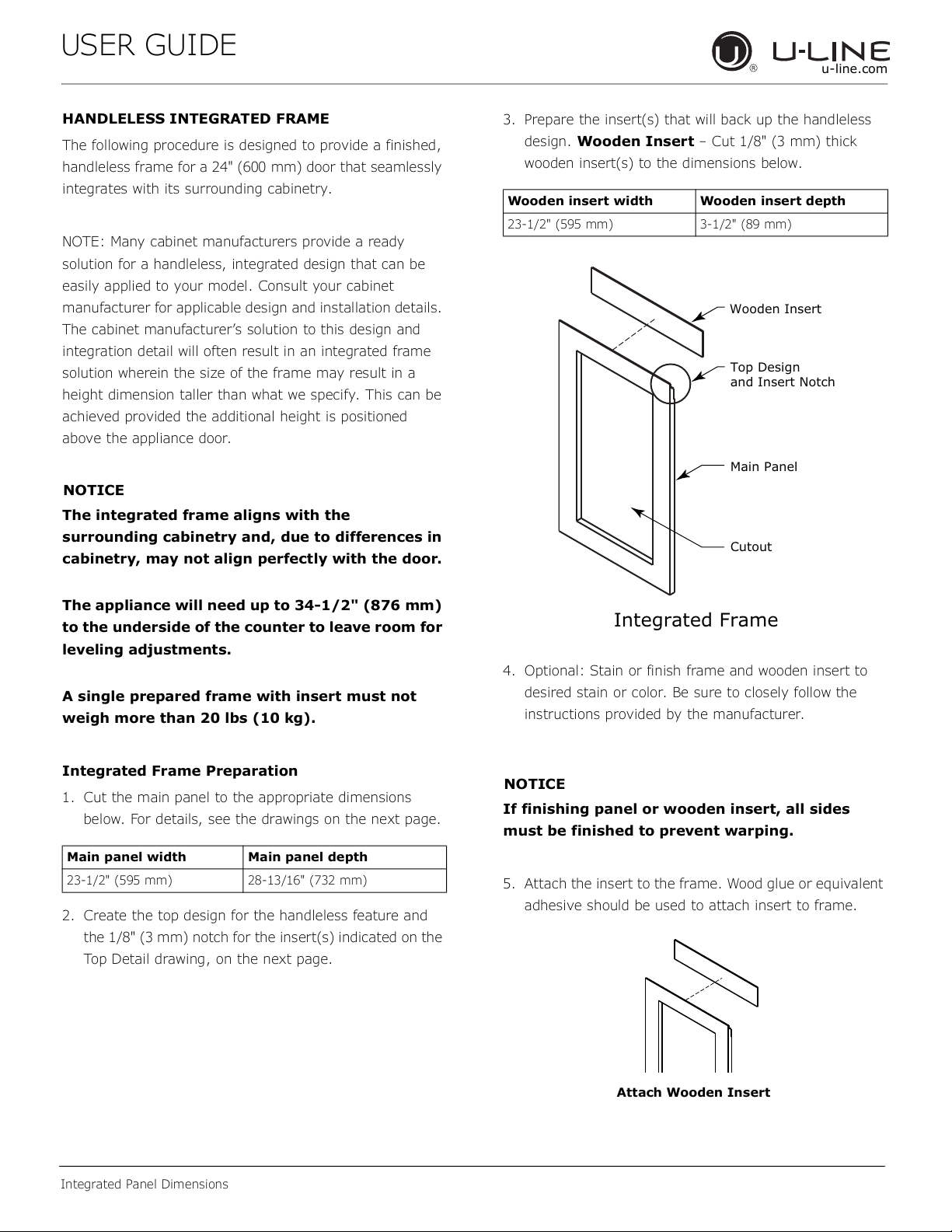
2. Create the top design for the handleless feature and
the 1/8" (3 mm) notch for the insert(s) indicated on the
Top Detail drawing, on the next page.
3. Prepare the insert(s) that will back up the handleless
design. Wooden Insert – Cut 1/8" (3 mm) thick
wooden insert(s) to the dimensions below.
4. Optional: Stain or finish frame and wooden insert to
desired stain or color. Be sure to closely follow the
instructions provided by the manufacturer.
NOTICE
If finishing panel or wooden insert, all sides
must be finished to prevent warping.
5. Attach the insert to the frame. Wood glue or equivalent
adhesive should be used to attach insert to frame.
Main panel width Main panel depth
23-1/2" (595 mm) 28-13/16" (732 mm)
Wooden insert width Wooden insert depth
23-1/2" (595 mm) 3-1/2" (89 mm)
Cutout
Integrated Frame
Main Panel
Wooden Insert
Top Design
and Insert Notch
Attach Wooden Insert
5
USER GUIDE
Integrated Panel Dimensions
u-line.com
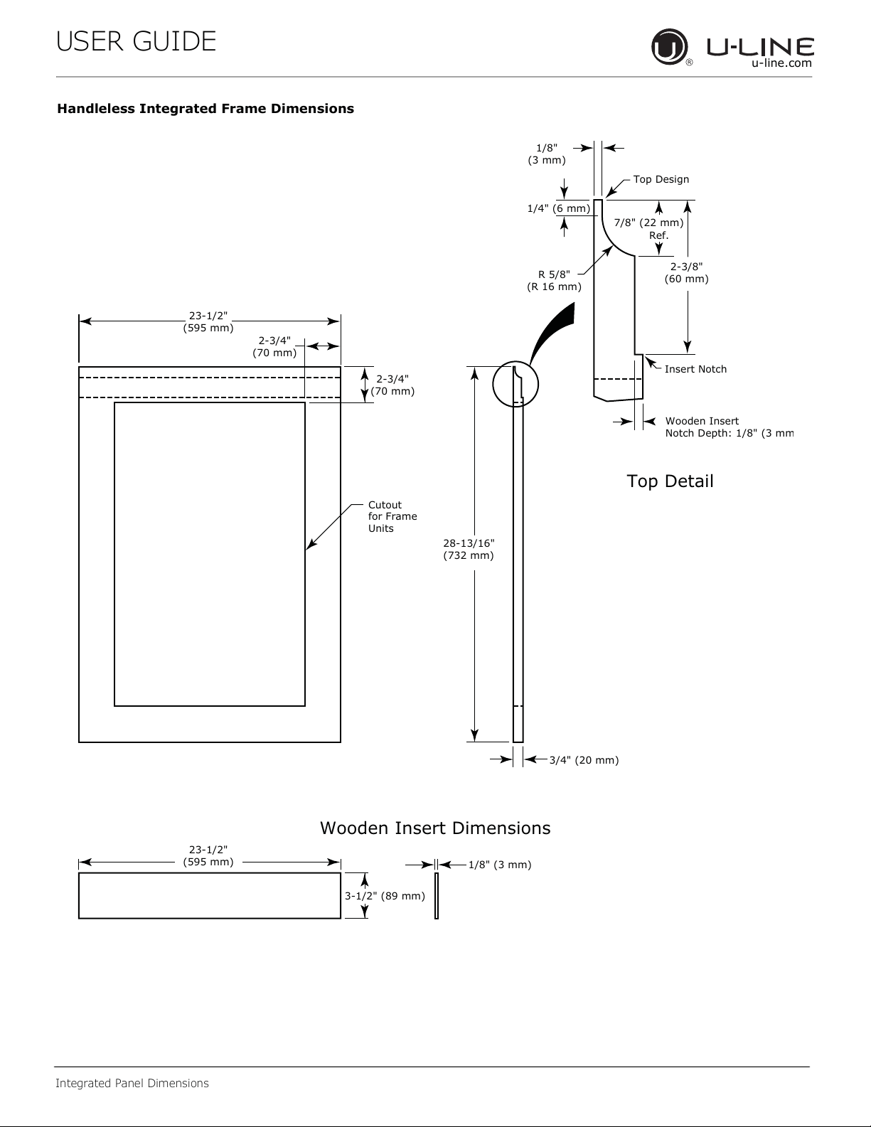
Handleless Integrated Frame Dimensions
3/4" (20 mm)
28-13/16"
(732 mm)
2-3/4"
(70 mm)
2-3/4"
(70 mm)
R 5/8"
(R 16 mm)
1/8"
(3 mm)
1/4" (6 mm)
Wooden Insert
Notch Depth: 1/8" (3 mm
2-3/8"
(60 mm)
7/8" (22 mm)
Ref.
Cutout
for Frame
Units
Top Detail
Insert Notch
Top Design
1/8" (3 mm)
3-1/2" (89 mm)
23-1/2"
(595 mm)
Wooden Insert Dimensions
23-1/2"
(595 mm)
6
USER GUIDE
Integrated Panel Dimensions
u-line.com
EXTENDED INTEGRATED FRAME
NOTICE
Due to differences in surrounding cabinetry the
panel may not perfectly align with door. The
procedure below is designed to provide a
finished panel that seamlessly integrates with
surrounding cabinetry.
Panel Preparation
An extended integrated panel can be used to maintain
alignment with an adjacent extended cabinet height or a
reduced toe-kick/grille application.
1. Cut the panels to the dimensions listed in the
appropriate diagram on the next page.
2. Optional: Stain or finish panel to desired stain or color.
Be sure to closely follow the instructions provided by
the manufacturer.
3. Optional: Install handles and hardware.
NOTICE
The door panel must not weigh more than 20 lbs
(10 kg).
It is important to ensure that all drilled holes are
drilled to the correct depth in order to avoid
splits in the wood when hardware is installed.
Appliance will need up to 34-1/2" (876 mm) to
the under side of the counter to leave room for
leveling adjustments.
When applying an integrated frame to a unit,
ensure that both sides are finished in order to
prevent warping. In some installations, the
panel may be visible through the glass while the
door is open.
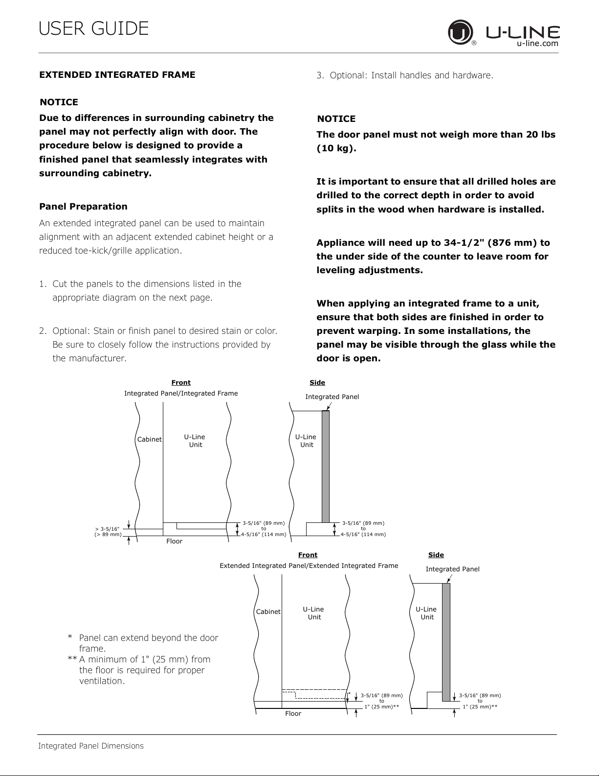
3-5/16" (89 mm)
to
4-5/16" (114 mm)
U-Line
Unit
U-Line
Unit
Integrated Panel
Integrated Panel/Integrated Frame
Front Side
Front Side
3-5/16" (89 mm)
to
4-5/16" (114 mm)
Floor
Cabinet
> 3-5/16"
(> 89 mm)
3-5/16" (89 mm)
to
1" (25 mm)**
U-Line
Unit
Extended Integrated Panel/Extended Integrated Frame
Floor
Cabinet
3-5/16" (89 mm)
to
1" (25 mm)**
*
U-Line
Unit
Integrated Panel
* Panel can extend beyond the door
frame.
** A minimum of 1" (25 mm) from
the floor is required for proper
ventilation.
7
USER GUIDE
Integrated Panel Dimensions
u-line.com
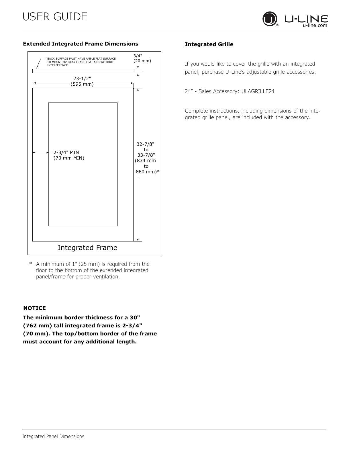
Extended Integrated Frame Dimensions
NOTICE
The minimum border thickness for a 30"
(762 mm) tall integrated frame is 2-3/4"
(70 mm). The top/bottom border of the frame
must account for any additional length.
BACK SURFACE MUST HAVE AMPLE FLAT SURFACE
TO MOUNT OVERLAY FRAME FLAT AND WITHOUT
INTERFERENCE
2-3/4" MIN
(70 mm MIN)
Integrated Frame
3/4"
(20 mm)
23-1/2"
(595 mm)
32-7/8"
to
33-7/8"
(834 mm
to
860 mm)*
* A minimum of 1" (25 mm) is required from the
floor to the bottom of the extended integrated
panel/frame for proper ventilation.
Integrated Grille
If you would like to cover the grille with an integrated
panel, purchase U-Line’s adjustable grille accessories.
24” - Sales Accessory: ULAGRILLE24
Complete instructions, including dimensions of the inte-
grated grille panel, are included with the accessory.
8