Loading ...
Loading ...
Loading ...
Part Number 550-142-302/0520
CGi
SERIES 4 — GAS-FIRED WATER BOILER — Boiler Manual
18
Venting — direct exhaust — installation
3f
1. Do not mix types or manufacturers of vent materi-
als.
2. Clean all joints before sealing. See vent manufac-
turer’s instructions for cleaning and sealing joints.
Use their specified sealant. Do not use screws.
3. Install vent pipe with seams on top of vent horizon-
tal runs. Follow requirements in Section
3e for vent
termination.
4. Maintain minimum 2” clearance from combustible
materials to vent pipe.
5.
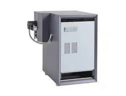
Vertical venting — See Figure 13. Follow vent
manufacturer’s instructions for venting through
roof.
• Vent pipe must extend through roof flashing,
jacket or thimble.
• Vent may pass through floor, inside wall or
concealed space when installed according to
vent manufacturer’s instructions.
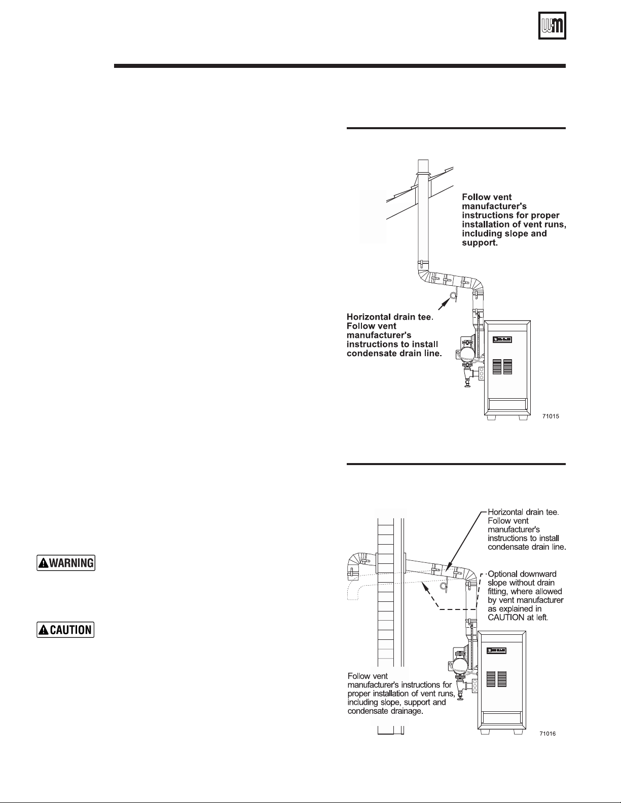
Sidewall venting — See Figures 14 and 15.
Vent must terminate at least one foot above
anticipated snow line. Vent must be termi-
nated only with:
• Tee or elbow with integral screen. (Tee may be
mounted either vertically or horizontally.
DO
NOT
use horizontal tee with CGi-7 or CGi-8.)
• Elbow and termination coupling with screen
(not available for StaR-34).
6. Do not seal vent pipe (slip connector for Saf-T Vent)
to inside or outside plate.
7. If passing through noncombustible wall, provide
hole diameter large enough to insert the vent pipe
(slip connector for Saf-T Vent).
8. Install horizontal drain tee as close as possible to
boiler, in first horizontal run. See
Figures 13 and 14.
9. Do not exceed the maximum vent system length
given in Table 4, page 15.
Condensate drain line — use only silicone tubing rated
for at least 400°F for the first 18” of condensate drain
line, then other non-metallic tubing may be used. Us-
ing any other material could cause flue gas leakage,
potentially resulting in severe personal injury, death or
substantial property damage.
On some installations, the condensate drain fitting may
be omitted, provided:
• Vent manufacturer shows this option in their instruc-
tions.
• Vent is sloped toward termination as shown in dotted
lines in
Figure 14.
• The vent is installed per Weil-McLain and vent
manufacturer’s instructions.
• Condensate drip page from such vents may accumu-
late on the ground below. Consider traffic in the area
to avoid hazard due to ice accumulation.
Figure 13 Direct exhaust vertical venting
Figure 14 Direct exhaust sidewall venting
Loading ...
Loading ...
Loading ...