Please ll in the following information for your NEW unit, carefully
read the instructions in this manual and le it for future reference.
MODEL NO.
SERIAL NO.
PURCHASED FROM
INSTALL DATE
1-800-523-7138
Continental Refrigerator
A Division of National Refrigeration
& Air Conditioning Products, Inc.
539 Dunksferry Road
Bensalem, PA 19020-5908
P 215-244-1400
F 215-244-9579
www.continentalrefrigerator.com
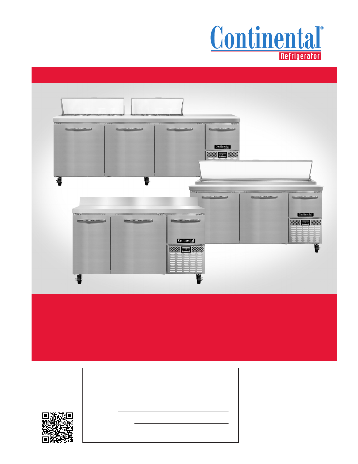
INSTALLATION AND OPERATIONS MANUAL
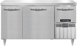
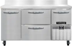
Refrigerated Bases & Pizza Prep Tables
Refrigerators & Freezers
SCAN this code
to download manual

Page
Receiving Your New Model ............................................................................................................................... 3
General Information and Important Operating Facts .................................................................................................. 3
Uncrating Your New Model................................................................................................................................ 3
Installation and Location .................................................................................................................................. 4
Ventilation ....................................................................................................................................................................................4
Floor Loads ..................................................................................................................................................................................4
Installing Casters and Leveling ....................................................................................................................................................5
Installing Legs and Leveling ........................................................................................................................................................5
Condensate Removal ...................................................................................................................................................................6
Door Adjustment ..........................................................................................................................................................................6
Hinge Tension Adjustment ...........................................................................................................................................................6
Removal and Replacement of Doors............................................................................................................................................7
Re-Hinging Doors ........................................................................................................................................................................7
Prep Top Pan Openings ...............................................................................................................................................................8
Interior Accessories ........................................................................................................................................ 8
Initial Cleaning Procedure ................................................................................................................................ 9
Start-Up Procedure ......................................................................................................................................... 9
Electrical Connections ..................................................................................................................................................................9
Start-Up Checklist .......................................................................................................................................................................10
Operation with Mechanical Thermostat ................................................................................................................ 10
Thermometer ..............................................................................................................................................................................11
Refrigeration System and Adjustment ........................................................................................................................................1 1
Defrost System ...........................................................................................................................................................................11
Operation with Electronic Control ....................................................................................................................... 12
Electronic Control Display and Buttons.......................................................................................................................................12
Initial Sequence of Operation ......................................................................................................................................................12
How to Calibrate the Electronic Control ......................................................................................................................................12
How to Change the Set-Point ......................................................................................................................................................12
How to Switch Controller Off/On ................................................................................................................................................13
Anti-Condensate Control (On) .....................................................................................................................................................13
How to Initiate a Manual Defrost ................................................................................................................................................13
How to Change the Defrost Interval ............................................................................................................................................13
High and Low Temperature Alarm ..............................................................................................................................................13
Electronic Control Error Codes ...................................................................................................................................................13
Maintenance ................................................................................................................................................ 14
Periodic Cleaning Procedure .......................................................................................................................................................14
General Preventative Maintenance ..............................................................................................................................................14
Care and Cleaning of Stainless Steel...........................................................................................................................................15
Parts and Service .......................................................................................................................................... 16
Placing a Service Call ..................................................................................................................................................................16
Obtaining Replacement Parts Under Warranty ...........................................................................................................................16
Obtaining Replacement Compressor Under Warranty ................................................................................................................16
End of Life Disposal of Refrigerated Equipment .........................................................................................................................16
Optional Accessories 17
Drawers: Removal and Adjustments ...........................................................................................................................................17
Installing Drawer Cage ................................................................................................................................................................17
Installing Overshelf or Double Overshelf.....................................................................................................................................18
Installing Front Breather Kit .......................................................................................................................................................19
Mounting Caster Support Plates .................................................................................................................................................19
Installing Electric Condensate Heater ..........................................................................................................................................20
Dial Thermometer and Calibration ..............................................................................................................................................20
Digital Thermometer and Calibration ..........................................................................................................................................21
Installing Pan Slide Cage ............................................................................................................................................................21
Remote Set-Up and Installation Guidelines.................................................................................................................................22
Fish File Base Models .................................................................................................................................................................23
Troubleshooting and Servicing Guide .................................................................................................................. 24
Wiring Diagrams ........................................................................................................................................... 26
Limited Extended Protection Warranty ................................................................................................................. 30
TABLE OF CONTENTS
3
OPERATIONS MANUAL
REFRIGERATED BASES & PIZZA PREP TABLES
IMPORTANT NOTE: The model and serial number should
be noted on the front cover of this manual, in the spaces
provided. If parts or service are ever needed for your unit,
this information will be required to verify warranty status
and to properly identify any parts that may be needed.
All cabinets must be given sufficient time to reach normal
operating temperature before placing any food inside cabinet
or pans (if equipped). For refrigerators, approximately 1 hour
of operation is required to lower the cabinet and pan tempera-
ture to 40°F (4°C). During pull-down of open top models, pans
should be in place and top lid should be kept closed. Freezers
require approximately 2 hours of operation to lower the cabinet
temperature to 0°F (-18°C) (see “Operation” section for further
information).
Prior to factory shipping, all products are performance-run
tested for a minimum of 12 hours providing a highly sophis-
ticated temperature recording exclusive to each individual
cabinet. This recording is supplied within this manual packet. A
final evaluation, including analysis of cabinet performance, leak
check, vibration, noise level and visual examination is made by
a qualified quality control team to assure a superior product.
The carrier signs to this effect when they accept the product for
shipping. To insure the maximum in safety and sanitation, all
models are listed under applicable Underwriters Laboratories
and National Sanitation Foundation standards.
CAUTION
RISK OF ELECTRICAL SHOCK
KEEP ELECTRICAL COMPONENTS AND CONTROLS DRY
- DO NOT SPRAY WITH WATER!
FAILURE TO FOLLOW THESE INSTRUCTIONS CAN
CAUSE A HAZARD & VOID FACTORY WARRANTY.
UNCRATING YOUR NEW MODEL
IMPORTANT: Your equipment should never be transport-
ed on legs/casters unless the cabinet bottom is properly
supported. Consult the factory for more information.
The protective packaging should remain on your cabinet to avoid
dents or scratches while transporting to the actual set-up loca-
tion. All shelving, accessories and legs or casters are carefully
packaged and secured inside your cabinet to prevent damage.
After moving unit to its final location, remove all the staples
from around the bottom of the crate using a pry bar. Slide the
cardboard carton up and off the unit, being careful not to rub
against the cabinet. Remove any accessories or boxes on the
skid. Dispose of all packaging materials properly.
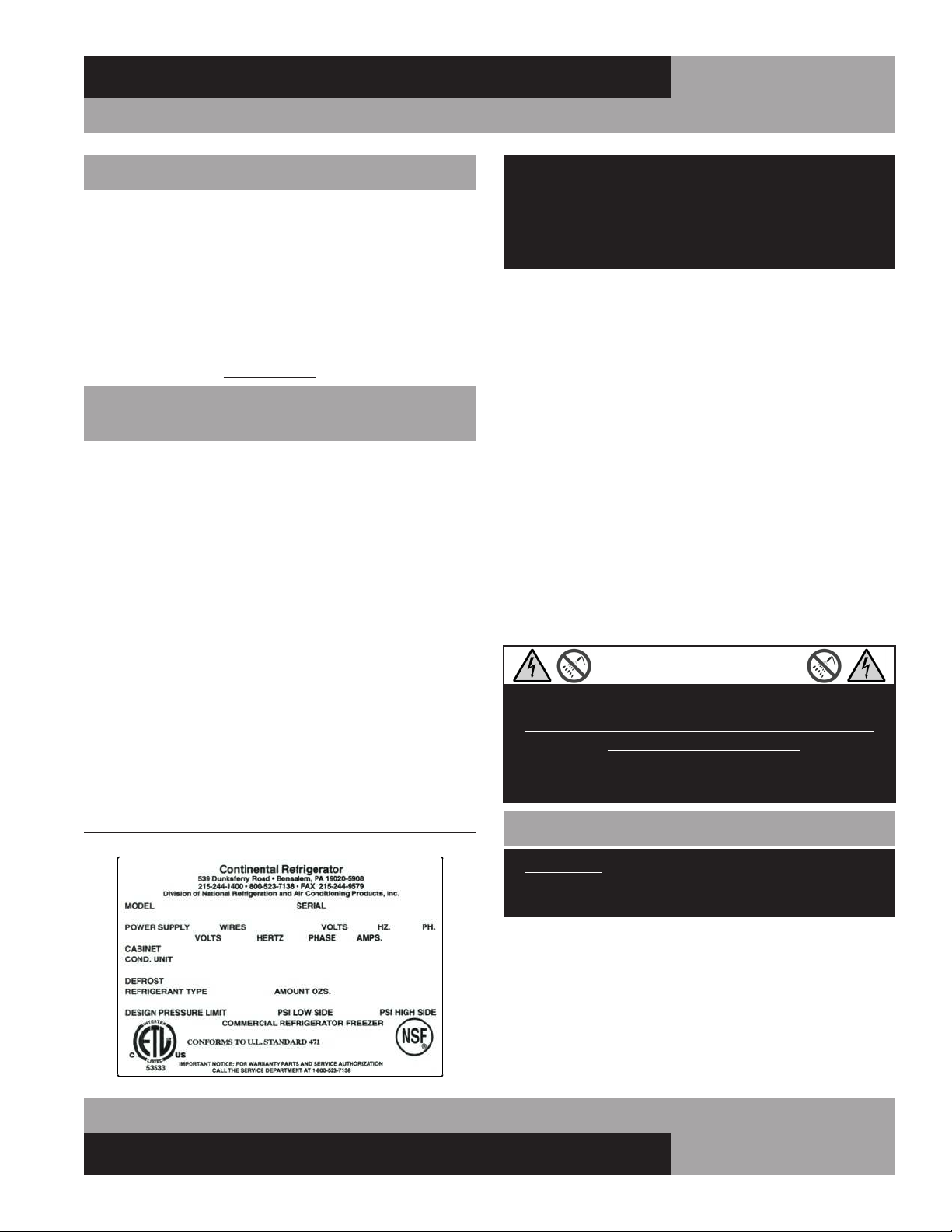
FIGURE 1: Data Tag
RECEIVING YOUR NEW MODEL
Congratulations on your purchase of Continental Refrigerator
superior foodservice equipment! When your shipment arrives,
thoroughly examine the packaging for any punctures, dents or
signs of rough handling. It is in your best interest to partially
remove or open the shipping container to examine the contents
for any missing accessories or concealed damage which may
have occurred during shipment. If the cabinet is damaged, it
must be noted on the carrier’s delivery slip or bill of lading
and a Freight Claim must be filed with the shipping company.
FREIGHT DAMAGE IS NOT COVERED UNDER WARRANTY.
GENERAL INFORMATION AND
IMPORTANT OPERATING FACTS
This manual has been compiled to aid in the installation, opera-
tion and maintenance of your equipment. Please read it and
familiarize yourself with your equipment, its operation and avail-
able accessories, to enjoy optimum performance.
This equipment is prohibited from use in California with
any refrigerants on the “List of Prohibited Substances” for
that specific end-use, in accordance with California Code of
Regulations, title 17, section 95374. This disclosure statement
has been reviewed and approved by NRAC, Inc. and NRAC, Inc.
attests, under penalty of perjury, that these statements are true
and accurate.
SERIAL DATA TAG
A serialized data tag is permanently attached to the inside right-
hand wall of your unit. (see Figure 1). In addition to identifying
the specific product, this label provides important information
regarding electrical requirements and refrigeration charge, as
well as agency listings and factory contacts.
4
REFRIGERATED BASES & PIZZA PREP TABLES
OPERATIONS MANUAL
erating equipment including ovens, fryers, dishwashers, steam
kettles, etc. Do not install in direct sunlight (where temperatures
may exceed 100°F) or in an unheated area (where temperatures
may drop below 55°F).
Air supply to the condensing unit is critical. Restricting airflow
places excessive heat load on the unit, adversely affecting its
operation and may cause premature failure. The condenser coil
must be kept clean and free from obstruction. Condenser air fil-
ters are not recommended, since they hinder airflow, especially
if they are not replaced frequently. Contact our factory Service
Department for more information.
For optimum performance, all models should be installed on
casters or legs (see “Installing Casters” or “Legs”) with a
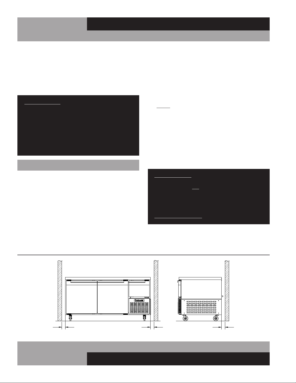
minimum 3” on each side and back of cabinet (see Figure 2).
This spacing will provide sufficient room for proper air circula-
tion and clearance to access components for cleaning and main-
tenance. If any of these conditions cannot be met, the installer
should provide special venting or air ducts, as required.
IMPORTANT NOTE: For maximum efficiency, your new
cabinet must be located where an unrestricted air supply
can circulate above and behind it. Never obstruct the face
of the condenser or the grill area in the front of the cabinet
and never place or store anything inside the cabinet
machine compartment. These rules are essential for long
life. FAILURE TO FOLLOW THESE GUIDELINES MAY
VOID YOUR WARRANTY.
FLOOR LOADS
The floor at the final location site must be level, free of vibration
FIGURE 2: Minimum Clearance Dimensions for Optimum Conditions (Except for Undercounter & Front Breathing Models)
Four (4) bolts secure the cabinet to the wooden skid. The bolts
are located at each end on the underside of the skid. In order
to remove these bolts, tilt the cabinet backwards and place
wooden blocks at each end in order to hold it in its tilted posi-
tion. Using a ¾” socket or open end wrench, remove the bolts
and carefully slide the cabinet off of the skid. After skid removal,
the cabinet should never be moved without dollies or rollers to
avoid damage to the cabinet bottom or floor.
IMPORTANT NOTE: Do not under any circumstances, lay
your new model on its front or sides. For a brief period of
time, you may lay the cabinet on its back, but only when
it’s properly blocked so as not to crush the louvered
venting panel and also to allow provision for your hands,
in order to set it in its upright position without damaging
the cabinet. Do not plug in and operate model for at
least three (3) hours after cabinet is set upright from
being on its back as this can damage the compressor.
INSTALLATION AND LOCATION
Before moving the cabinet to its final point of installation, mea-
sure all doorways or passages to assure clearance. If additional
clearance is needed, you can remove the cabinet doors (see
“Removal of Doors and Door Adjustment”) and lids (when
equipped) (see “Removing Lid and Hood”).
VENTILATION
The final location site of your air cooled refrigerator or freezer
must provide a sufficient quantity of cool, clean air. All refrigera-
tion systems operate more efficiently and trouble-free with cool,
dry air circulation. Avoid locations near heat and moisture gen-
5
OPERATIONS MANUAL
REFRIGERATED BASES & PIZZA PREP TABLES
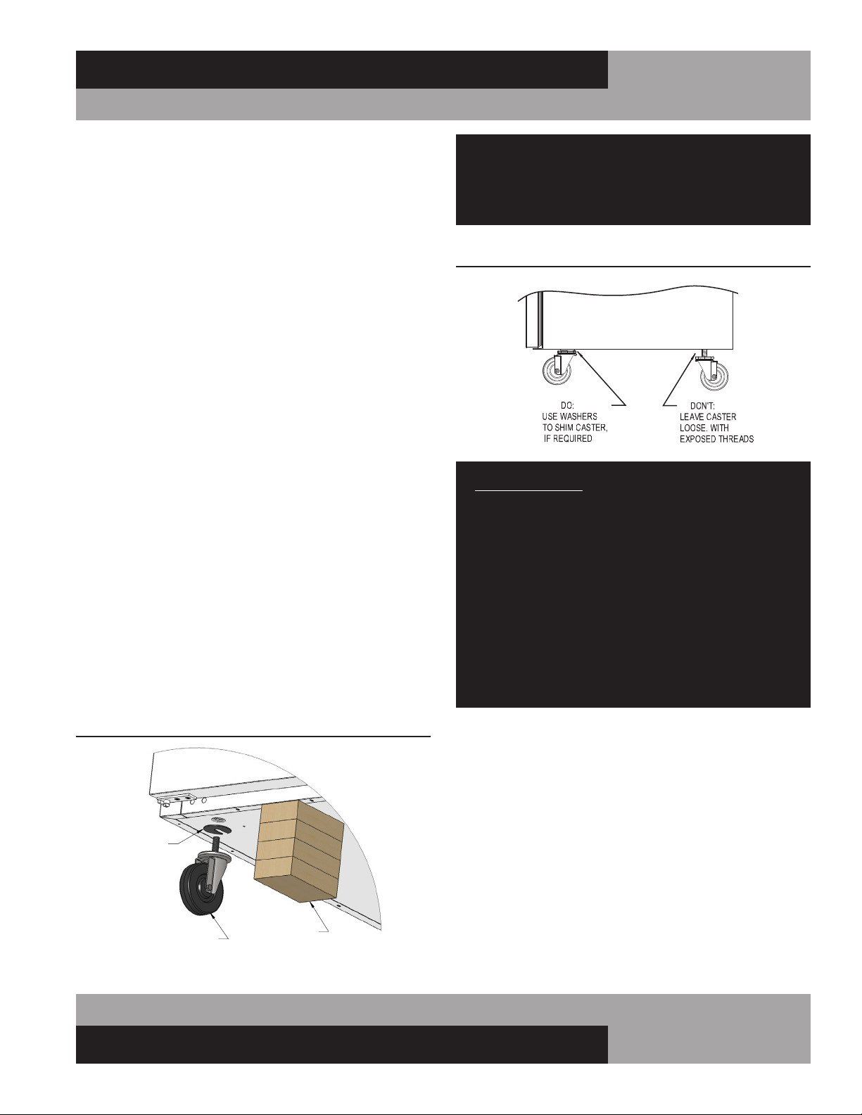
FIGURE 3A: Casters Must be Tight to Cabinet Bottom
Do not attempt to level casters by unscrewing them
from the cabinet and leaving them loose, as this will
cause damage to the cabinet and leg hole threads,
voiding all warranties.
IMPORTANT NOTE: It is extremely important that your
cabinet is perfectly level for proper operation. If it is not
level, the following adverse conditions may occur:
1. The door(s) will not be properly aligned and
consequently will not provide a good seal.
2. Your unit may run excessively.
3. An excessive amount of ice will accumulate inside
the cabinet, around the door opening(s) and on the
finned evaporator coil. If allowed to continue, ice will
eventually block the coil and the unit will fail. This
can result in the loss of all food stored in the cabinet.
4. Defrost water will fail to drain properly and will
overflow the evaporator coil drain pan and into the
cabinet of both refrigerator and freezer models.
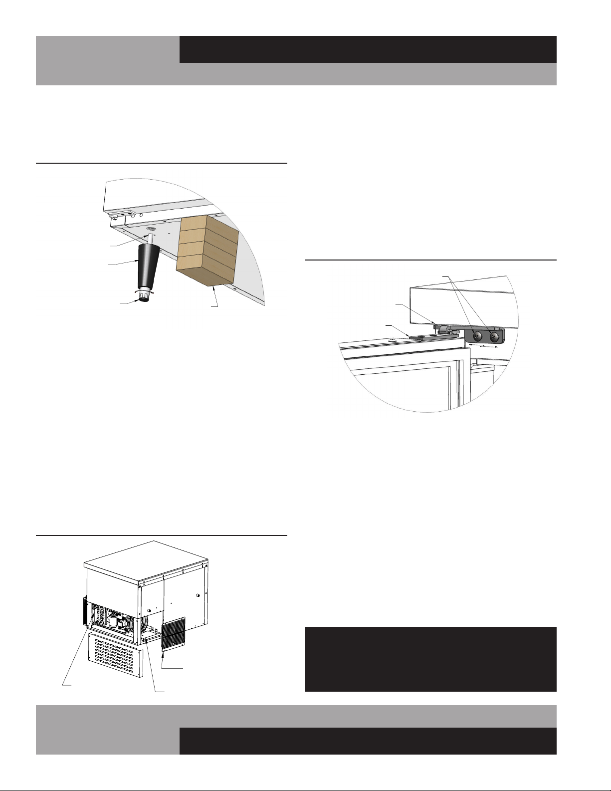
INSTALLING LEGS AND LEVELING
If your new unit is supplied with adjustable legs, they will be
packed in the accessory carton in the cabinet. Your cabinet will
have either four (4) or (6) threaded mounting holes on the bot-
tom of the cabinet (see Figure 4). In order to install the legs,
carefully tip the cabinet back, adding four (4) 2” wood blocks
underneath, and simply screw the threaded leg studs into the
case bottom front leg holes. Repeat this procedure by tilting the
cabinet in the opposite direction and install the remaining legs.
Make sure the legs are tightened extremely well or the entire
model will sway or rock with each opening or closing of the
doors, possibly causing damage to the case bottom. This pro-
cedure should be performed close to the final installation site.
and strong enough to support the total combined weights of
your new model plus the maximum product load which might
be placed into it. Keep in mind that all the weight is concentrated
at the caster or leg locations. To estimate the possible product
weight, assume that each cubic foot of storage space weighs
approximately 35 pounds. Multiply 35 pounds by the amount
of cubic feet in the cabinet to obtain the product load weight.
For example, a 20 cubic foot refrigerator can hold approximately
700 pounds of product (35 x 20). Assuming the cabinet itself
weighs 300 pounds, the total combined weight of cabinet and
product is approximately 1000 pounds. Therefore, the floor in
this example must be able to support up to 1000 pounds.
INSTALLING CASTERS AND LEVELING
If your new unit is supplied with swivel casters, they will be
packed in the accessory box that came with your cabinet.
Casters should be installed only when the cabinet is close to
its final installation site. To install casters on your new model,
place wooden blocks along the back, at each end. Tilt the cabi-
net back, using the wood blocks to help hold the cabinet in its
tilted position. Locate the large threaded holes on the bottom
of the cabinet and screw the threaded caster studs into the
mounting holes, closest to the front of the unit. Repeat this
procedure by tilting the cabinet in the opposite direction and
installing the remaining casters. Make sure the casters are
tightened extremely well (see Figure 3 & 3A). If the casters are
not installed tightly, the cabinet will be unstable and may sway
or rock, which can damage the cabinet.
If the height of a caster needs to be raised, shims must be
installed under the casters which need leveling. Extra large
washers, available at most hardware or furniture stores, can be
used to shim casters, or contact the factory for caster shims.
OPTIONAL
CASTER SHIM
(CM1-2476)
CASTER
BLOCKS
FIGURE 3: Installing Casters
6
REFRIGERATED BASES & PIZZA PREP TABLES
OPERATIONS MANUAL
DOOR ADJUSTMENT
All doors are aligned at the factory, however vibration during
transit may cause them to shift and adjustment may be neces-
sary. If a door requires realignment, carefully open the door
(90°) and loosen, but do not remove the mounting screws
securing both the top (see Figure 6) and bottom (see Figure
8) hinge brackets to the cabinet. Move the door to the desired
position by hand or by gently tapping on the edge with a rubber
mallet. Hold the door firmly in place and tighten all mounting
screws securely, above and below the door. Check alignment
and repeat adjustment if necessary.
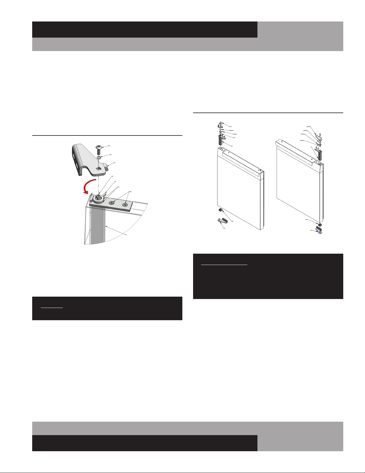
HINGE TENSION ADJUSTMENT
The self-closing doors on your unit have a spring-loaded hinge
cartridge concealed in the door (see Figure 7) with a hold-open
feature and a cushioned stop. When the door is fully opened
(115°) the hinge should be tension free. When the door is
moved between the open and closed position, the spring-loaded
hinge will automatically rotate the door toward the closed posi-
tion. For proper operation, self-closing doors must be installed
with the spring-loaded hinge mechanism set to apply tension in
the proper direction (see Figure 8).
To adjust spring tension, open the door fully (115°) so it stays
in position when released. Remove the mounting screws secur-
ing the cartridge bracket to the cabinet (see Figure 6). The
bracket should stay in position when released, but if it is moved
or bumped, it may snap into the closed position.
THE HINGE CARTRIDGE IS SPRING LOADED AND MAY
SNAP BACK ON FINGERS WHEN BRACKET IS LOOSE.
WEAR WORK GLOVES AND USE CAUTION WHEN
REMOVING MOUNTING SCREWS!!
LEG
BLOCKS
THREADED
END
TURN FOOT CLOCKWISE
TO REDUCE HEIGHT, OR
COUNTERCLOCKWISE
TO INCREASE HEIGHT.
FIGURE 6: Hinge Adjustment
To assure your cabinet is level, all legs are equipped with bullet-
type leveling bolts. These bolts can be turned by hand or by
wrench, clockwise or counterclockwise to level the cabinet.
CONDENSATE REMOVAL
All models utilize a unique hot air condensate water evaporat-
ing system which is completely self-contained and no further
assembly or maintenance is required (see Figure 5). In some
adverse conditions such as high ambient temperature, high
humidity, extremely heavy usage, frequent loading for prolonged
periods of time, or heavy pan loading, the amount of conden-
sate water generated could overflow the pan. If this occurs, the
plastic drain tube from the cabinet can be diverted directly to
a floor drain, bypassing the condensate pan. Alternatively, an
optional electric condensate heater may be purchased as an
accessory. An electric condensate heater is also supplied with
all remote models. To install the electric heater, see “Installing
Electric Condensate Heater” in the “Optional Accessories”
section at the back of this manual.
FIGURE 4: Leg Installation
FIGURE 5: CPA/CRA Components (Rear View)
DC POWER SUPPLY
(WHEN EQUIPPED)
DRAIN PAN
REMOVE SCREWS FROM
ACCESS PANEL AND
LIFT OFF TO REMOVE
FIGURE 5A: CPA/CRA Components
(Rear Veiw)
7
OPERATIONS MANUAL
REFRIGERATED BASES & PIZZA PREP TABLES
hinge cartridge bracket to the cabinet below the door. Lower the
door down carefully, to avoid bumping the cartridge bracket,
and slide it off the pivot pin bracket over the door. To reinstall,
reverse this procedure and follow the instructions above to set
the hinge tension and adjust the door properly.
RE-HINGING DOORS
IMPORTANT NOTE: DOORS ARE FIELD REVERSIBLE,
BUT DIFFERENT HINGE BRACKETS ARE REQUIRED.
HAVE YOUR MODEL AND SERIAL NUMBER READY AND
CONTACT THE FACTORY FOR THE PARTS NEEDED FOR
YOUR UNIT.
Remove the door and hinge cartridge bracket from the cabinet,
as described above (see Figure 7). Remove the pivot bracket,
located at the opposite edge of the door (see Figure 8) by
loosening the (2) mounting screws. Remove the hinge cartridge
from the door by removing the (2) screws and sliding the car-
tridge out. Remove the plastic pivot insert from the opposite end
of the door by carefully prying it out with a flat-blade screwdriver
or putty knife. Remove the remaining “filler screws” from the
face of the cabinet and reinstall them in the threaded holes
where the brackets were originally mounted.
To re-assemble the reverse-hinged door, obtain the correct
cartridge bracket and pivot bracket for the top and bottom of the
“opposite-hand” door (see Figure 8 for parts identification).
Follow the steps above, in reverse order.
Use a hinge cartridge bracket as a wrench by positioning it
upside down with the square hole over the square hub on the
spring mechanism (see Figure 7). Carefully turn the square hub
on the cartridge in the direction shown to tighten the spring.
The mechanism should snap to a neutral position. Remount
the hinge as shown and repeat the procedure described above
until the hinge snaps back when it is moved from the open-door
position towards the closed-door position.
REMOVAL AND REPLACEMENT OF DOORS
If you need to remove a door from your cabinet, first identify
the location of the spring-loaded hinge cartridge (see Figure 8).
Depending on the age of your cabinet, the cartridge is located
either on the top or the bottom of the door.
CAUTION: THE HINGE CARTRIDGE IS SPRING LOADED
AND THE BRACKET MAY SNAP TOWARDS THE DOOR!
For doors with spring cartridge on the top: open the door fully
(115°) and remove the mounting screws (see Figure 6) secur-
ing the hinge cartridge bracket to the cabinet above the door
(the bracket should stay in the open position, but if it is moved
it may snap closed). Pick the door straight up, being careful not
to bump the cartridge bracket, and lift it off the pivot pin bracket
below the door. To reinstall a door, reverse this procedure and
follow the instructions above to set the hinge tension and adjust
the door properly.
For doors with spring cartridge on the bottom: open the door
fully (115°) and remove the mounting screws securing the
FIGURE 7: Spring-Loaded Hinge Mounting
FIGURE 8: Door Hinge Components
8
REFRIGERATED BASES & PIZZA PREP TABLES
OPERATIONS MANUAL
INTERIOR ACCESSORIES
Your new unit is shipped with (1) shelf per section and (4) pilas-
ter clips for each shelf.
SHELVING INSTALLATION
Pilaster strips which support the shelving are secured to the
cabinet walls with special pilaster screws which allow the strips
to be readily removed for cleaning without the use of tools. Shelf
clips are easily installed by inserting them into the pilasters at
the desired shelf location and shelf installation is as simple as
placing the shelf on the clips (see Figure 10).
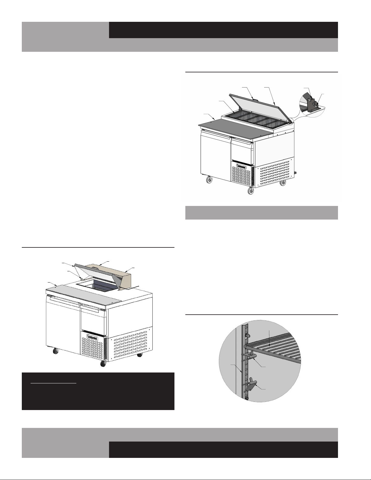
PREP TOP PAN OPENINGS
Sandwich top models are provided with food pans and divider
bars. All pans must be kept in place whenever your unit is oper-
ating and lids should be closed whenever possible for optimum
performance. To remove the lid over the pans (see Figure 9),
lift it 1/2 way up and carefully push in on one end at the bottom
corner, so the pivot pin comes out of the mating hole in the
hood. Swing the end of the lid forward, so it clears the end of
the hood. Slide the entire lid sideways, so the pivot pin on the
opposite end is free from the hood. If you have an insulated lid,
to remove the liner and insulation, take out the screws along
the back edge, let the back of the liner drop down and rotate it
so the front edge of the liner disengages from the front of the
lid. To remove the hood from the cabinet, take out the screws
located inside each end and along the back edge.
Pizza Prep Tables are provided with a flat lid to cover the pan rail.
All pans must be in place when your unit is operating and lids
should be closed whenever possible for optimum performance.
To remove the lid covering the pans on Pizza Prep models (see
Figure 9A) rotate it 1/2 way up and lift the lid forward and up,
so the hinge pins disengage from the hinge bracket. If you need
to disassemble an insulated lid, see instructions above.
IMPORTANT NOTE: The top opening on your sandwich
top must be completely filled with pans at all times, even
if some pans are empty, to maintain air flow for proper
cabinet and pan temperature.
FIGURE 9: Sandwich Top Refrigerator Base Models
FIGURE 9A: Pizza Prep Table Pan Rail
HINGE DETAIL
CUTTING
BOARD
HANDLE
FOOD
PANS
LID
PIVOT
PIN
HINGE
BRACKET
FIGURE 10: Standard Shelf Pilaster
PILASTER
STRIP
PILASTER CLIP
INSTALLED
PILASTER CLIP
INSTALLING
SHELF
INSTALLING
9
OPERATIONS MANUAL
REFRIGERATED BASES & PIZZA PREP TABLES
GFI/GFCI RECEPTACLES
Ground-Fault Circuit Interrupter (GFCI or GFI) devices are not
recommended for most commercial refrigerators and freezers,
since nuisance trips may occur, typically due to moisture. This
can cause temporary loss of power, which may result in high
storage temperatures and potentially unsafe food product.
Building codes in some areas may require certain 115 volt
receptacles to be protected by a GFI. If you need to connect your
equipment to a protected circuit, a properly sized, commercial
grade GFI circuit breaker should be used on a separate, isolated
power supply. Or a qualified electrician may be able to hard wire
your equipment, eliminating the need for a GFI device. Contact
Continental’s Service Department before making any modifica-
tions to your cabinet, to avoid loss of warranty.
NOTE: GFI RECEPTACLES ARE NOT RECOMMENDED,
PRODUCT LOSS OR SERVICE PROBLEMS RESULTING
FROM NUISANCE TRIPS, CONNECTION TO A DEFECTIVE
OR IMPROPER POWER SUPPLY, AND UNAUTHORIZED
MODIFICATIONS TO YOUR EQUIPMENT CAN CAUSE A
HAZARD AND WILL VOID FACTORY WARRANTY.
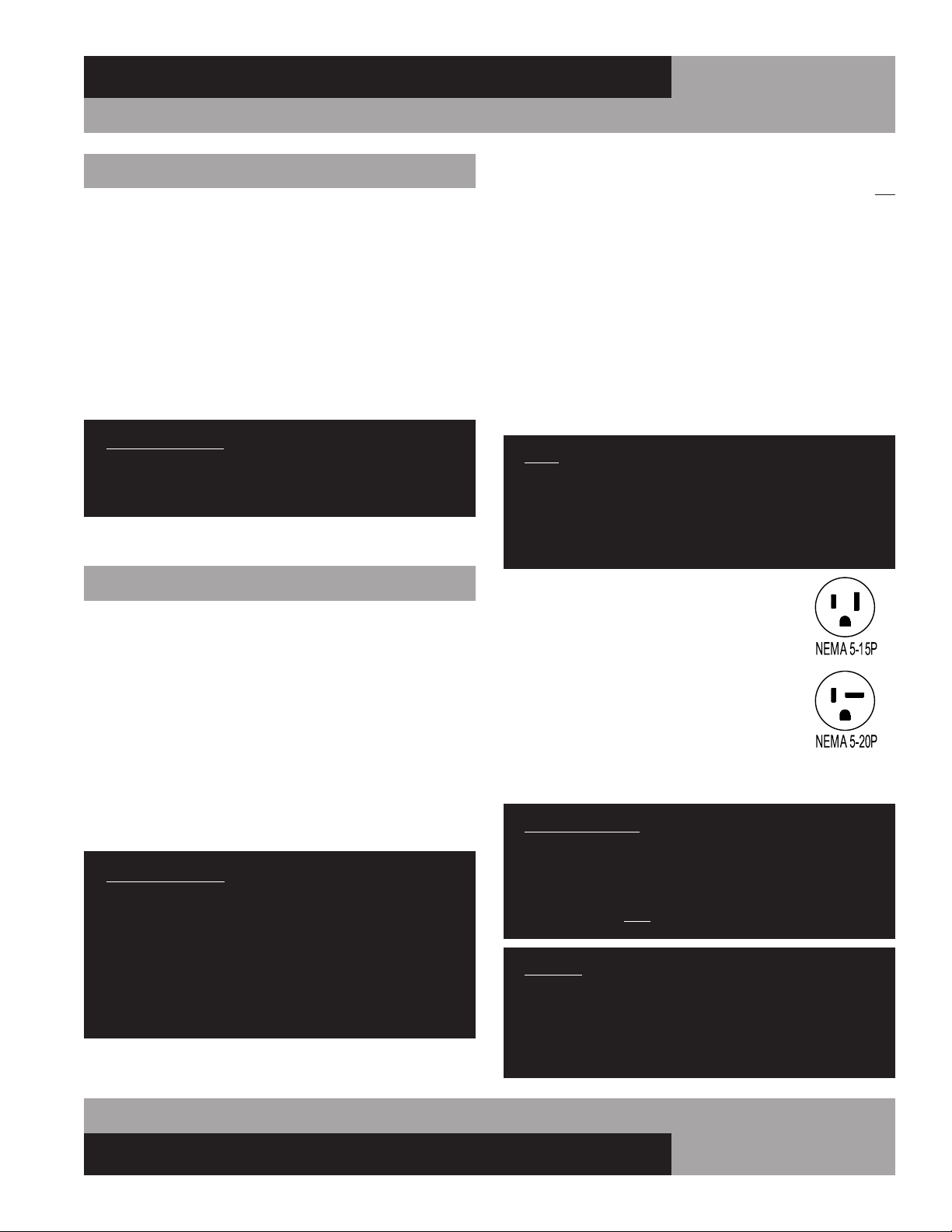
115 VOLT, 60 HZ, 1 PHASE CONNECTION
All 115 volt models are provided with a factory
installed, UL approved 15-amp power cord and
NEMA 5-15P plug, or a 20-amp power cord and
NEMA 5-20P plug. To insure proper operation,
this equipment must be plugged into a NEMA
compatible, grounded receptacle that can sup-
ply the full voltage and amperage stated on the
serial plate (see Figure 1).
Some 115 volt models (including CPA118) require 20 amp sup-
ply power and must be plugged into a NEMA 5-20R receptacle.
IMPORTANT NOTE: A SEPARATE, ISOLATED, PROPERLY
SIZED POWER SUPPLY MUST BE PROVIDED. GFCI
DEVICES AND/OR EXTENSION CORDS SHOULD NOT
BE USED. PRODUCT LOSS, AS WELL AS PROBLEMS
RESULTING FROM NUISANCE TRIPS OR HIGH/LOW
VOLTAGE, ARE NOT COVERED UNDER WARRANTY.
CAUTION: IF UNIT IS UNPLUGGED OR DISCONNECTED
FOR ANY REASON, ALLOW 5-6 MINUTES BEFORE
TURNING THE UNIT BACK ON TO ALLOW THE SYSTEM
TO EQUALIZE. DISREGARDING THIS PROCEDURE
COULD CAUSE AN OVERLOAD AND PREVENT THE UNIT
FROM OPERATING.
09/03/10
INITIAL CLEANING PROCEDURE
Prior to start-up and before placing any product inside of your
new model, the interior of the cabinet should be thoroughly
cleaned. Remove the protective film (which is clear on some
models) from all interior sides, bottom and other internal metal
panels, by working the corner loose and slowly pulling the film
back. Washing with a mild soap and warm water solution is
recommended for cleaning the aluminum and stainless steel
surfaces of your cabinet. This should be followed by cleaning
with a baking soda solution (three (3) tablespoons of baking
soda to each quart of warm water). Wipe down thoroughly with
a damp cloth or sponge that has been soaked in clean water and
wrong out thoroughly, and dry with a clean, soft cloth.
IMPORTANT NOTE: Never use harsh detergents, clean-
ers, scouring powders or chemicals when cleaning your
model. Failure to dry the interior surfaces after cleaning
may result in a streaking or staining of the metal.
Complete cleaning procedures and precautions are listed in the
(“Periodic Cleaning Procedure” under “Maintenance”).
START-UP PROCEDURE
ELECTRICAL CONNECTIONS
To insure proper operation, your new model must be connected
to an individual circuit that can supply the full voltage as stated
on the cabinet serial data plate. For correct voltage, power draw,
and wire accommodations, check the data on the serial data
plate located on the inner right wall of your new model. Verify
that this information exactly matches the electrical character-
istics at the installation location. An electrical wiring diagram,
located on the inside compressor compartment rear, next to
the electrical console box, should also be consulted during
connection. For reference, a copy of each electrical wiring dia-
gram is located towards the back of this manual (see “Wiring
Diagrams” section).
IMPORTANT NOTE: The condensing unit supplied with
all self-contained models is designed to operate within a
range of +/-10% of the voltage indicated on the cabinet
serial data plate. Full voltage of the correct rating, on
an isolated line, not affected by the operation of other
electrical appliances, must be available to the refrigera-
tion unit at all times. Burnout of the compressor due to
exceeding high or low voltage limits is easily detected
and will void the factory warranty.

10
REFRIGERATED BASES & PIZZA PREP TABLES
OPERATIONS MANUAL
SPECIAL VOLTAGE CONNECTIONS
When models are ordered from the factory with special, optional
voltages, connections should be made as required on the electri-
cal wiring diagram provided on the inside compressor compart-
ment rear next to the electrical console box.
START-UP CHECKLIST
After your unit has been installed and electrically connected in
accordance with this manual, please take time to check the fol-
lowing before loading product, to assure trouble free operation:
Sufficient clearance provided (see “Ventilation”)
Separate supply with correct voltage
(see “Electrical Connections”)
Cabinet level and casters/legs tight
(see “Installation and Location”)
Doors close and seal properly
(see “Door Removal and Adjustment”)
Correct cabinet temperature
(see “System and Adjustment”)
Thermometer calibrated (see “Thermometer”)
Refrigeration lines free of kinks and vibration
(see “Refrigeration System”)
All fans rotate freely (see “Refrigeration System”)
Freezers only: defrost clock set
(see “Freezer System and Adjustment”)
Pilaster clips secure and shelves level
(see “Shelving Installation”)
Pizza & Sandwich: All pans and dividers in place
(see “Pizza Prep and Sandwich Top Pan Openings”)
All packaging discarded and cabinet cleaned
(see “Periodic Cleaning”)
The system should run smoothly and quietly in accordance
with generally accepted commercial standards. If any unusual
noises are heard, turn the unit off immediately and check for any
obstructions of the condenser or evaporator fans. Fan motors,
fan blades, or fan housings can be jarred out of position through
rough handling in transit or during installation.
OPERATION WITH MECHANICAL THERMOSTAT
All cabinets must be given sufficient time to reach normal oper-
ating temperature before placing any product inside cabinet.
Refrigerators are designed to maintain an ideal cabinet tem-
perature of 38° to 40°F (3.3° to 4.4°C), approximately 1 hour
of operation is required to reach this temperature. During pull-
down of open top models, pans should be in place and top lid
should be kept closed. Freezers are designed to maintain an ideal
cabinet temperature of -4° to 0°F (-20° to -18°C), approximately
2 hours of operation are required to reach this temperature.
THERMOMETER
Your new model has a non adjustable hanging thermometer
located inside the cabinet, mounted on the coil housing cover
(see Figure 11A). This thermometer is maintenance-free and
needs no further calibration. If your cabinet has a dial or
digital thermometer mounted on the grill, see the “Optional
Accessories” section of this manual for additional information.
All adjustable thermometers are pre-calibrated at the factory, to
accurately show the cabinet temperature. While in transit, your
cabinet will be subjected to more jarring and vibration than at
any other time in its life and the thermometer may require some
adjustment at start-up. During periods of heavy use, when the
cabinet doors are opened repeatedly or remain open for an
extended period of time, the temperature inside your cabinet
may temporarily exceed the “safe” temperature indicated on the
display. This is normal, as warm air outside the cabinet mixes
with the cold air inside the cabinet, or if warm product is loaded
into the cabinet. If your thermometer continues to show a tem-
perature above the “safe” zone for your refrigerator or freezer,
close the doors and make sure they seal tight. Keep the doors
closed for at least 30 minutes and check the display again. If it
still indicates high temperature, see “Optional Accessories”
section of this manual for additional information.
REFRIGERATION SYSTEM AND ADJUSTMENT
All refrigerated storage cabinets are designed for the purpose
of holding pre-chilled or frozen product and although they are
capable of cooling or freezing small quantities of fresh product,
they are not designed to be blast chillers or ice-cream freezers.
Do not attempt to chill or freeze bulk quantities of fresh food,
ice-cream, or other products in your refrigerated storage unit.
Sandwich and Pizza Prep Tables are not intended for overnight
product storage in the top opening or pan rail.
11
OPERATIONS MANUAL
REFRIGERATED BASES & PIZZA PREP TABLES
DEFROST SYSTEM
(Pizza Prep and Freezer Base Models)
All Pizza Prep Tables feature a positive “off-cycle” defrost
system, with a timer that automatically initiates and terminates
compressor off-cycles, to ensure the evaporator remains frost-
free, even under heavy usage. All freezer defrost systems feature
a timer that initiates defrost cycles with a fail-safe cut-off time of
20 minutes, an automatic limit switch that provides temperature
termination of the defrost cycles, and electric heaters for posi-
tive thawing of the evaporator coil and drain pan, for optimum
performance.
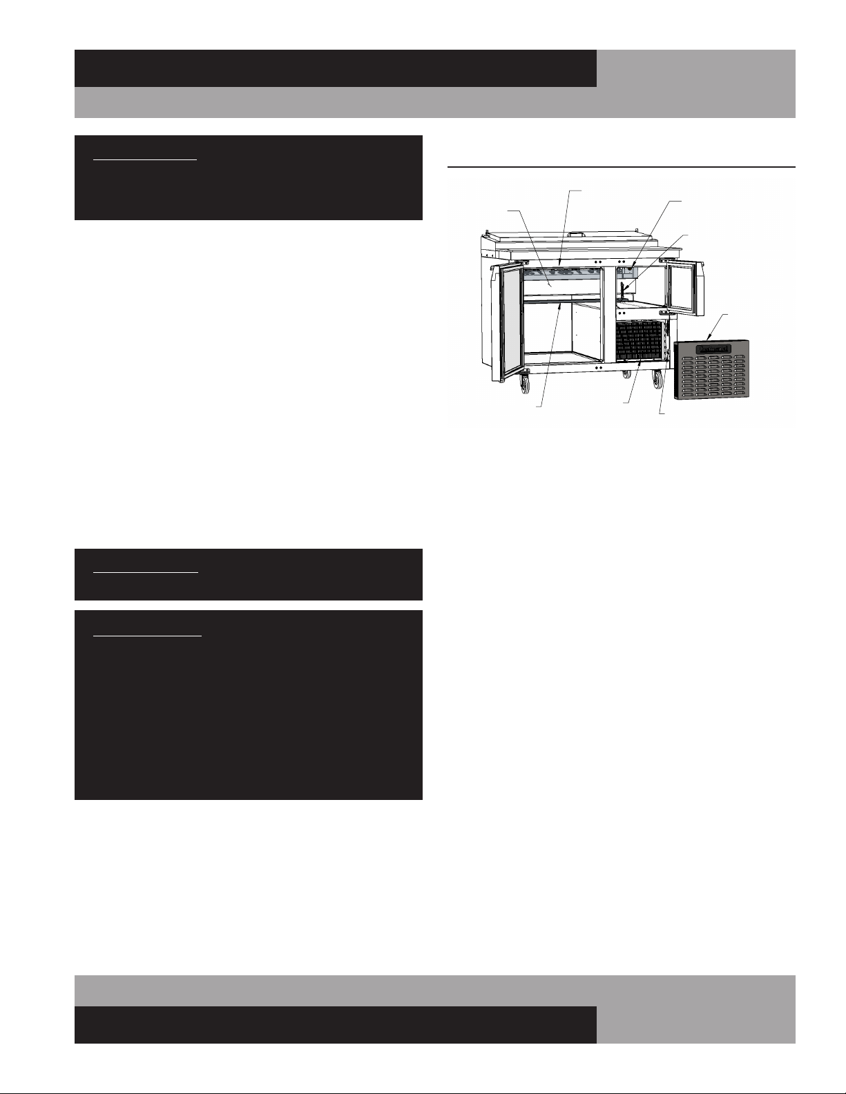
The defrost timer on all pizza prep and freezer base models is
located in the machine compartment, behind the front grill on
CPA & CFA models (see Figure 11). If desired, the start time
for a defrost cycle can be adjusted by turning the knob on the
defrost timer clockwise until defrost cycle begins (compressor
and all fans will terminate). Defrost will begin at this same time
every day at 8-hour intervals. For example, if an 8:00 am defrost
is desired, at 8:00 am turn the timer knob to initiate defrost. A
defrost cycle will start every day at 8:00 am, 4:00 p.m., 12:00
am. If there is a loss of power to the cabinet, the defrost timer
will have to be reset to maintain the same defrost cycle times.
FIGURE 11: CPA/CRA Components (Front View)
EVAPORATOR
COVER
FAN MOTORS
(BEHIND PANEL)
THERMOMETER
TEMPERATURE
CONTROL
EVAPORATOR
DRAIN PAN
DEFROST TIMER
GRILL
(REMOVED)
CONDENSER
(BEHIND GRILL)
IMPORTANT NOTE: Do not attempt to bulk chill or freeze
product in your storage cabinet and do not leave pans
with food in your Sandwich top or Pizza Prep rail over-
night.
All models have an extra large, full length, performance-rated,
plasticized fin coil for extended life, with uniquely directed air
flow distribution that keeps product at uniformly constant tem-
peratures. The evaporator coil and temperature control are easily
accessible from inside the cabinet (see Figure 11).
All self-contained refrigerators and Pizza Prep Tables are
designed and factory set to maintain an average cabinet temper-
ature of 38° to 40°F (3.3° to 4.4°C). All self-contained freezers
are factory set to maintain an average cabinet temperature of -4°
to 0°F (-20° to -18°C). If an adjustment is necessary to maintain
cabinet temperature within these ranges, locate the temperature
control (see Figure 11) and place a screwdriver into the slotted
knob on the temperature control. Turn clockwise no more than
1/4 turn for a colder cabinet temperature or counterclockwise for
a warmer cabinet temperature. Allow the cabinet to stabilize for
at least 30 minutes and recheck the temperature. Further adjust-
ments out of the factory design temperature range should only
be made by a qualified refrigeration mechanic.
IMPORTANT NOTE: Turning a thermostat fully counter-
clockwise turns the refrigeration compressor “off.”
IMPORTANT NOTE: All refrigerators and Pizza Prep
Tables are designed with an automatic, “off-cycle”
defrost system which means that defrosting occurs auto-
matically when the compressor is not operating during an
off-cycle. Do not set the thermostat too cold where the
cabinet temperature will fall below 35°F (1.7°C) because
the evaporator will become blocked by ice since the com-
pressor off-cycle will be considerably shortened. This
will result in loss of product stored within the cabinet and
require service to defrost the evaporator and re-adjust
the thermostat.
12
REFRIGERATED BASES & PIZZA PREP TABLES
OPERATIONS MANUAL
3. The control may be preprogrammed to initiate a defrost by
time interval.
HOW TO CALIBRATE THE ELECTRONIC CONTROL
The controller temperature display can be calibrated if required.
Before attempting to calibrate the temperature display, check the
display by placing a pre-calibrated temperature sensing device in
the center of the refrigerated compartment and keep the doors
closed for at least 15 minutes. The temperature display should
read the same temperature as the sensing device, within +/-2°F.
If not, follow these instructions to calibrate.
1. Press and HOLD the “SET” button until “PS” appears flash-
ing in the display. Release the “SET” button.
2. Press the “UP” button until “/C1” appears in the display.
Release the “UP” button.
3. Press and release the “SET” button. The current value of the
offset will appear in the display.
4. Press the “UP” button to increase or the “DOWN” button to
decrease the offset value.
5. Press and HOLD the “SET” button for 5 seconds to confirm
and save the new value. When complete, the current tem-
perature will be displayed. RELEASE the “SET” button.
EXAMPLE: If a sensing device in the cabinet reads 38°F and the
control display shows 41°F, follow steps above and decrease the
current offset by 3°F. If the current offset was 0, change to -3.
HOW TO CHANGE THE SET-POINT
Refrigerators are factory set to maintain an average temperature
of 38°F. Freezers are factory set to maintain an average tempera-
ture of 0°F. To change set-point:
1. Press and HOLD the “SET” button until the current set-point
begins flashing. Release the “SET” button.
2. Press the “UP” or “DOWN” button to adjust to the new set-
point value.
3. Press and release the “SET” button to lock in the new set-
point. The control will now resume normal operation with
the new set-point.
a. During defrost, the defrost icon will appear in the display
and the compressor will turn off until a preprogrammed
temperature or time is reached. During this time for freez-
ers only, the evaporator fan(s) will also turn off and the
defrost heater will be energized.
b. After a preprogrammed evaporator temperature has been
reached, there may be a short delay for both the compres-
sor and evaporator fan(s) to restart.
c. After the defrost cycle is completed, the control will
resume normal operation.
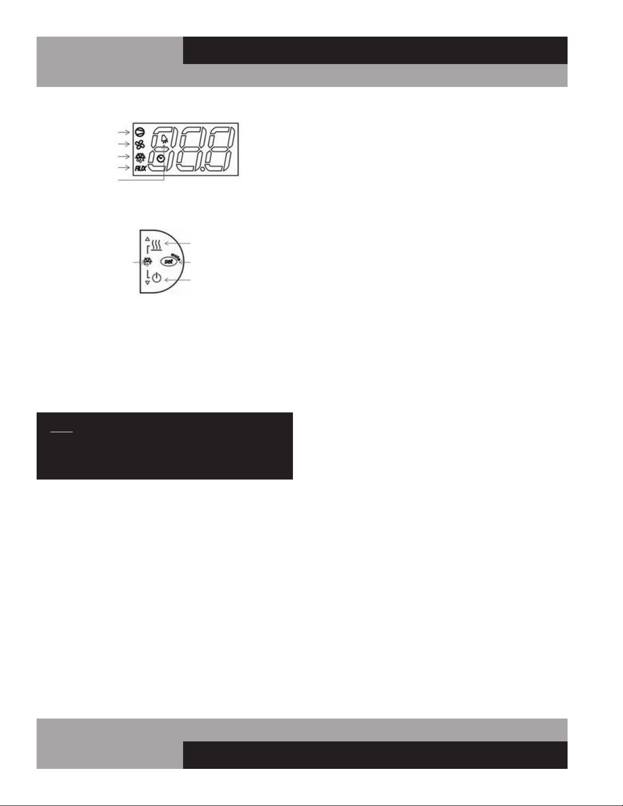
ELECTRONIC CONTROL DISPLAY AND BUTTONS
The control icons shown above will be illuminated when the
associated function is active. If an icon is flashing, it means the
function will be activated after the controller delays are finished.
• The “AUX HTRS/UP” button is used for activation or
deactivation of the auxiliary anti-condensate heaters or for
increasing values.
• The “SET/MUTE” button is used to lock in a new value or
to silence the alarm beeper.
• The “POWER/DOWN” button is used to turn the unit on/off
or for decreasing values.
• Press the “UP” and “DOWN” buttons simultaneously for 3
seconds to put into manual defrost.
NOTE: The electronic control has 2 or 3 probes. There is
the regulation probe in the return air stream, there is an
evaporator probe located in the evaporator coil, and if the
unit has fascia heaters, there will be an ambient probe.
INITIAL SEQUENCE OF OPERATION
1. Cabinet is plugged in.
2. The control will cycle the compressor on and off determined
by the SET-POINT and DIFFERENTIAL.
COMPRESSOR
EVAP FAN
DEFROST
AUX HTRS
ALARM
AUX HTRS
(UP)
SET
(MUTE)
POWER
(DOWN)
DEFROST
2 BUTTONS
a. The display will illuminate with the current cabinet
temperature.
b. The compressor icon, fan icon, and the aux heater icon
may flash for a period of time, indicating normal
delayed start-up.
c. After the start-up delay, the compressor and evaporator
fan(s) will start if the control is calling for cooling.
a. The SET-POINT is the preprogrammed temperature which
shuts off the compressor.
b. The DIFFERENTIAL is the preprogrammed temperature that
is added to the SET POINT temperature that will start the
compressor.
EXAMPLE: Set-Point 36°F and the differential is 4°F the com-
pressor will cycle off at 36°F and back on at 40°F.
13
OPERATIONS MANUAL
REFRIGERATED BASES & PIZZA PREP TABLES
HOW TO SWITCH THE CONTROLLER OFF/ON
The controller can be switched OFF. The display will still be
active but all systems operated by the control will be OFF.
1. To turn the controller OFF, press and HOLD “POWER” but-
ton for 5 seconds. When in the OFF mode, “OFF” will alter-
nate in the display with the current appliance temperature.
2. To turn the controller back “ON”, press and HOLD “POWER”
button for 5 seconds. The controller will resume normal
operation.
ANTI-CONDENSATE CONTROL (ON)
1. To see the current state of the aux heaters (anti-conden-
sate), press and HOLD “AUX HTR” button for 1 second.
RELEASE “AUX HTR” button. The display will show the cur-
rent state of the heater when the button is pressed.
2. To change the current state of the AUX Heaters, press and
HOLD “AUX HTR” button. The display will show the current
state of heater operation. After 5 seconds, the heater will
switch to the opposite state and the display will return to
displaying the cabinet temperature. RELEASE the button.
The control has a built in energy saving feature for the AUX (anti-
condensate) heaters. When in the ON position, the AUX icon
may not illuminate indicating the AUX heaters are not currently
energized. The control will automatically energize the AUX heat-
ers when the conditions require these heaters to be activated.
HOW TO INITIATE A MANUAL DEFROST
This is used when a one-time additional defrost may be neces-
sary to clear accumulated ice from the evaporator coil.
1. Press and HOLD “UP” and “DOWN” buttons simultaneously
for 5 seconds.
2. After 5 seconds, the defrost icon will illuminate. RELEASE
“UP” and “DOWN” buttons.
HOW TO CHANGE THE DEFROST INTERVAL
This is used to increase or decrease the frequency of defrosts.
If the interval is set at “8”, a defrost will occur every 8 hours. If
you need more defrosts, lower this value.
1. Press and HOLD “SET” button until “PS” appears flashing
in the display. Release “SET” button.
2. Press “UP” button until “DI” (defrost interval) appears in
the display. Release “UP” button.
3. Press and RELEASE “SET” button. The current defrost inter-
val will appear in the display.
4. Press “UP” or “DOWN” button to adjust to the new defrost
interval.
5. Press and HOLD “SET” button to lock in this new value.
When the display returns back to cabinet temperature,
release “SET” button.
NOTE: Defrost cycles are time initiated and temperature
terminated with a maximum time cut-off.
HIGH AND LOW TEMPERATURE ALARMS
The controller has high and low alarm set-points. These values
can be modified per the end user requirements. There is a pre-
programmed time delay for the alarm to activate to eliminate
nuisance alarms. To change the alarm threshold values:
1. Press and HOLD “SET” button until “PS” appears flashing
in the display. Release “SET” button.
2. Press “UP” button until “AL” (Low Alarm Setting) or “AH”
(High Alarm Setting) appears in the display. Release “UP”
button.
3. Press and RELEASE “SET” button. The current alarm setting
will be shown.
4. Press “UP” or “DOWN” button to get the desired alarm
set-point.
5. Press and HOLD “SET” button for 5 seconds to confirm and
save the new value. When complete, the current tempera-
ture will be displayed. Release “SET” button.
NOTE: When in an alarm condition, the display will alter-
nate between the cabinet temperature and alarm code.
“AL” when in a low temperature alarm condition and “AH”
when in a high temperature alarm condition. The control
will also beep and the alarm icon will activate when in an
alarm condition. To silence the alarm beeper for the active
alarm just press and release the “SET/MUTE” button.
ELECTRONIC CONTROL ERROR CODES
If there is a regulation probe error, the display will just show
alarm code “E0” and not flash the cabinet temperature. If there
is a probe error, you must contact your service provider
immediately.
Alarm Code Alarm Description Notes
E0 Regulation Probe Error Located in return air stream
E1 Evaporator Probe Error Located in evaporator coil
E2 Ambient Probe Error Located on side of electrical box
LO Low Temperature Alarm Reference “AL” parameter
HI High Temperature Alarm Reference “AH” parameter
• If there is an error code “E0”, the control will operate the
appliance in a preprogrammed ON/OFF cycle based on time,
not temperature.
• If there is an error code “E1”, the control will still go into a
defrost but will terminate on time, not temperature.
• If there is an error code “E2”, the aux heaters will not oper-
ate.

14
REFRIGERATED BASES & PIZZA PREP TABLES
OPERATIONS MANUAL
Carefully wash all of the vinyl door gaskets with clean
water, dry them and check for any damage, which may
affect the seal. Failure to dry all surfaces completely may
cause water stains or streaking on the aluminum or stain-
less steel finish.
4. Return all accessories to their original locations, reconnect
the power. Wait at least 1 hour before reloading product.
CLEANING PRECAUTIONS
NEVER USE HARSH DETERGENTS, ABRASIVE
CLEANERS, OR CHEMICALS CONTAINING HALOGENS
(CHLORINE, FLUORINE, IODINE, ETC.) WHEN
CLEANING YOUR UNIT. CONCENTRATED CHEMICALS
CAN CAUSE DISCOLORING, ALWAYS WIPE THEM OFF
IMMEDIATELY IF CONTACT OCCURS. SEE “CLEANING
OF STAINLESS STEEL” FOR MORE INFORMATION.
AVOID SPLASHING THE CABINET WITH WATER AND
CHEMICALS WHEN MOPPING FLOORS OR CLEANING
OTHER EQUIPMENT AROUND IT.
GENERAL PREVENTATIVE MAINTENANCE
The most important thing you can do to maintain any refrigera-
tor or freezer and extend its life, is to keep the condenser clean.
Performance of the air-cooled condensing unit, located on the
side of the cabinet, depends exclusively upon the amount of air
passing through the condenser fins. Your refrigerator or freezer
will run more efficiently, consume less energy, and provide a
maximum of trouble-free service throughout its lifetime if the
condenser coil is kept clean and an adequate supply of clean,
cool air is provided at all times. Periodically (at least once a
month) it is important to inspect the condenser coil for any
debris or blockage that may have accumulated.
If the condenser coil is dirty or dusty, disconnect the cabinet
power supply and use a stiff brush to wipe away any dirt and
debris from the condenser fins. Using a vacuum cleaner with a
brush attachment may aid in this process. After cleaning, restore
electrical service to your cabinet.
IMPORTANT!
AFTER-MARKET CONDENSER FILTERS ARE NOT
PERMITTED BECAUSE THEY HINDER AIRFLOW.
FAILURE TO KEEP THE CONDENSER CLEAN AND
FREE FROM OBSTRUCTIONS WILL CAUSE EXCESSIVE
COMPRESSOR LOAD, REDUCING THE PERFORMANCE
OF YOUR UNIT. THIS CAN RESULT IN PREMATURE
FAILURE AND WILL VOID YOUR WARRANTY.
MAINTENANCE
SAFETY PRECAUTIONS
DISCONNECT POWER BEFORE ATTEMPTING TO WORK
ON OR CLEAN EQUIPMENT. DO NOT ATTEMPT TO
REMOVE ANY COVERS OR PARTS YOURSELF, AS
THIS CAN EXPOSE DANGEROUS, HIGH VOLTAGE
WIRING. SERVICE SHOULD ONLY BE PERFORMED BY
A QUALIFIED TECHNICIAN.
ALWAYS ROUTE POWER CORDS AWAY FROM AREAS
WHERE THEY CAN BE WALKED ON OR DAMAGED BY
OTHER EQUIPMENT. YOUR APPLIANCE IS EQUIPPED
WITH A POLARIZED, GROUNDED POWER PLUG. NEVER
ATTEMPT TO REMOVE THE GROUND POST OR USE
A NON-POLARIZED ADAPTER, WITHOUT PROPERLY
GROUNDING THE EQUIPMENT.
CONDENSER FINS ARE MADE FROM THIN METAL AND
HAVE SHARP EDGES. ALWAYS WEAR GLOVES AND
USE CAUTION WHEN WORKING ON OR AROUND THE
CONDENSING UNIT TO PREVENT CUTS AND AVOID
DAMAGING FINS, TUBING AND OTHER COMPONENTS.
KEEP ELECTRICAL COMPONENTS AND CONTROLS DRY.
DO NOT SPRAY WITH WATER! FAILURE TO FOLLOW
THESE INSTRUCTIONS CAN CAUSE A SAFETY HAZARD
AND VOID FACTORY WARRANTY.
PERIODIC CLEANING PROCEDURE
It is always best to clean your refrigerator or freezer when the
product load in your cabinet is as its lowest level. To clean the
interior or exterior cabinet surfaces, follow these procedures:
1. Disconnect your cabinet from its power supply and remove
all product from inside.
2. Open all doors and allow the cabinet to reach room temp-
erature. Remove all accessories (shelves, clips, pans, etc.)
from inside and wash them with a baking soda and warm
water solution, wipe thoroughly with clean water. Dry all
accessories completely with a soft clean cloth.
3. Once the cabinet has reached room temperature, wash the
inside and outside surfaces with a solution of warm water
and baking soda. Pay particular attention to the face of the
cabinet, as any residue or debris can impair the door seal.
For slightly more difficult cleanups, ammonia or vinegar in
warm water can be used. Wipe down thoroughly with a
damp cloth or sponge that has been soaked in clean water
and wrung out thoroughly, and dry with a clean, soft cloth.
15
OPERATIONS MANUAL
REFRIGERATED BASES & PIZZA PREP TABLES
CARE AND CLEANING OF STAINLESS STEEL*
*Some information and graphics for this section were obtained from “Stainless
Steel Equipment Care and Cleaning” brochure, published by the North American
Association of Food Equipment Manufacturers (NAFEM).
Contrary to popular beliefs, stainless steel can rust, if not prop-
erly cared for and maintained (That’s why it’s called stain-LESS
steel, not stain-PROOF steel.)
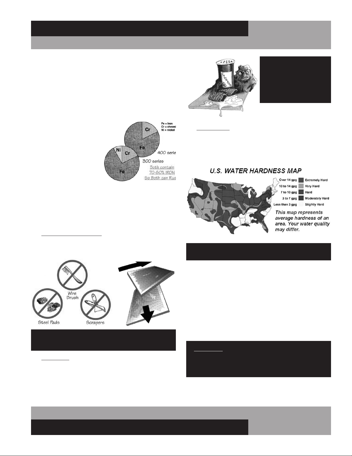
All steel is primarily made of
iron. Stainless steels contain
other metals, such as chromi-
um and nickel, that provide an
invisible film on the surface of
the steel that acts as a shield
against corrosion. As long as
this invisible layer is intact and
not broken or contaminated,
the metal will retain its cor-
rosion protection and remain
stain-less.
There are 3 basic things that can break down the protective
layer on your stainless steel, which must be avoided:
1. MECHANICAL ABRASION is caused by things that
scratch the surface of the metal. Only use soft cloths or
plastic scouring pads to clean and always scrub in the
same directions as the metal grain.
DO NOT USE: abrasive cleaners, steel pads, wire
brushes, scrapers or knives to clean your equipment.
2. CHLORIDES are found in water, salt, food and worst
of all, many cleaners. Only use chloride-free, alkaline-
based, non-abrasive cleaners. Always wipe thoroughly
with cool, clean water and dry with a soft towel. A solu-
tion of 1 tablespoon baking soda mixed with 1 pint water
can be used to remove tough stains.
DO NOT USE: abrasive
cleaners, chemicals with
chlorides or muriatic
acid to clean your
equipment.
3. HARD WATER causes spots and stains on stainless steel
surfaces, particularly when it is heated. Find out the hard-
ness of your water and treat it properly, if needed. Use a
water filter and softeners if you have hard water. Club soda
can be used to remove streaks or spots.
DO NOT USE: hot or hard water to clean stainless steel.
CLEAN YOUR STAINLESS STEEL REGULARLY using the proper
tools and cleaners. After cleaning, always wipe, wipe, wipe
thoroughly with cool, clean, clear water.
CHECK ALL OF YOUR EQUIPMENT PERIODICALLY. If you see
any signs of rust, clean the area immediately, with a plastic
scrubbing pad. If surface rust is removed promptly, permanent
corrosion, pits and cracks may be avoided. Special stainless
steel polishes, that can help restore the protective coating on
your equipment, are available from a variety of retailers.
IMPORTANT: If these recommendations are not followed,
the protective film on your stainless steel can break down
and your equipment may begin the long walk down the
dark road of corrosion.

16
REFRIGERATED BASES & PIZZA PREP TABLES
OPERATIONS MANUAL
OBTAINING REPLACEMENT
PARTS UNDER WARRANTY
If replacement parts are required for a unit under warranty,
contact Continental’s Service Department. New parts will be
sent from the factory and, when applicable, a Return Goods
Authorization (RGA) will be issued to return old parts. The RGA
number must appear on the packaging of any parts returned, or
they will not be accepted. If a service agent uses a part from their
stock, Continental will replace it with a factory part.
OBTAINING REPLACEMENT
COMPRESSOR UNDER WARRANTY
If the compressor should fail within the first twelve (12) months
of use, or within twenty (20) months from the date code on the
compressor, an “over-the-counter” exchange must be made
at an authorized Copeland, Danfoss, Embraco, or Tecumseh
wholesaler.
After the first year, the compressor motor is covered under an
extended “parts only” warranty. The customer is responsible for
any labor charges and any additional parts that may be required.
Contact the Service Department to obtain a replacement com-
pressor through one of the following methods:
• Continental will supply a replacement compressor
at no charge and pay for regular freight. (If expe-
dited freight is requested, the end user, dealer or
service agent is responsible for additional charg-
es and must provide credit card information.
• A compressor can be purchased locally and
Continental will either replace the stock unit with
a new factory compressor, or offer an allowance
towards the purchase of a replacement compres-
sor, up to: $100 for 1/5hp to 1/3hp; $250 for
1/2hp to 3/4hp; $350 for 1hp to 2hp.
The data tag from the defective compressor (or compres-
sor model, serial number and date code, if the tag cannot be
removed) must be included with any reimbursement request.
END-OF-LIFE DISPOSAL
OF REFRIGERATED EQUIPMENT
Your unit is designed and built to provide many years of reli-
able service. At the end of its useful life, please follow the steps
below for safe disposal, to help avoid accidents and to protect
the environment.
1. Remove all doors, to eliminate any potential for accidental
child entrapment.
PARTS AND SERVICE
Continental is committed to providing the best customer service
in the industry. All new units come with a Limited Extended
Protection Warranty (see “Warranty” section of this manual for
details). If a problem arises with your equipment, please contact
our Service Department at 1-800-523-7138. One of our Service
Specialists will do everything possible to solve the problem as
quickly as possible.
ITEMS NOT COVERED UNDER WARRANTY INCLUDE, BUT ARE
NOT LIMITED TO:
• Preventative maintenance: cleaning condenser
coils and other components.
• Consumables: light bulbs, door gaskets, batteries.
General hardware adjustments: cabinet leveling,
casters/legs, doors/hinges.
• Problems due to: inadequate installation or supply
power; improper maintenance, operation, or abuse.
• Compressor failure due to: dirty condenser, insuffi-
cient clearance/ventilation, excessive temperatures.
• System adjustments and calibrations, including:
controls, thermometer and expansion valves.
Consult the Table of Contents in the front of this man-
ual for detailed information on the items listed above.
Contact Continental’s Service Department with any
additional questions.
PLACING A SERVICE CALL
In order to receive prompt service, always be prepared to pro-
vide your: cabinet model and serial number; cabinet location
name and date installed; contact name and phone number; plus
a description of the problem.
During normal business hours (Monday to Friday, 8am to 5pm
Eastern) contact the Service Department at: 800-523-7138, prior
to any warranty service work being performed.
After normal business hours, or on weekends you can notify our
Service Department by sending an email to:
leaving a message in the general mail box. Be sure to provide the
information listed above. Contact Continental Refrigerator the
following business day, during normal business hours, to verify
the status of your call.
17
OPERATIONS MANUAL
REFRIGERATED BASES & PIZZA PREP TABLES
If the drawer fronts need adjustment (once all drawers are
installed and closed), loosen the five screws that hold the drawer
front to the drawer body. Move the drawer front into position
desired and re-tighten all screws.
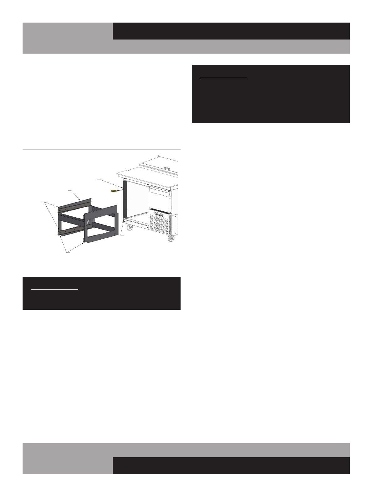
INSTALLING DRAWER CAGE
To convert your cabinet from doors to drawers, you will need a
drill with a 1/8” bit, a Phillips bit (or a Phillips-Head screwdriver
(or drill/driver with Phillips bit), and a rubber mallet. Take the
door off the section you want to convert, by following instruc-
tions in the “Removal of Doors” section of this manual. Take the
drawers out of the mounting cage, by following instructions in
the “Removal of Drawers” section of this manual.
Position the drawer mounting cage in front of the cabinet open-
ing as shown (see Figure 13). Lift the cage above the trim along
the bottom of the opening, so it is aligned to go straight into the
cabinet. Carefully slide the drawer cage into the unit opening. It
is a snug fit and some pressure may be need to be applied at
the corners, to clear the breaker around the opening. A rubber
mallet can be used to gently tap on the ends of the drawer cage
cross mullion, to force the fasteners past the side breakers. The
straighter the cage is pushed in, the easier it will be to install.
When the cage is in as far as it will go, the notches at the front
of the cage should surround the breaker corners at the bottom.
The face of the drawer cross mullion should be relatively flush
with the front face of the cabinet, to provide an even surface for
the drawer gaskets to seal properly around the openings. The
cage should sit relatively flat on the floor and against the back
wall step inside the cabinet.
2. All refrigerant should be removed from the system by a
qualified technician and disposed of properly, or reclaimed.
(Intentional venting of many refrigerants into the air is harm-
ful and prohibited; violators are subject to fines). All refriger-
ant oil should be drained from the compressor and discarded
appropriately.
3. Properly dispose of the cabinet and refrigeration system
components. The majority of the metal in your unit (stainless
steel or aluminum cabinet shell and doors, steel shelving and
compressor, copper refrigerant lines, etc.) can be recycled.
Many recycling facilities will dispose of the unit free of
charge, or pay you for scrap value of the material content.
OPTIONAL ACCESSORIES
Continental offers a variety of accessories for your unit.
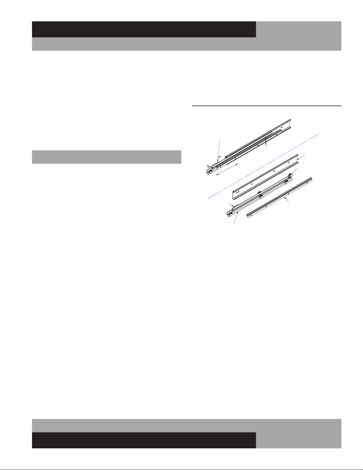
DRAWERS: REMOVAL AND ADJUSTMENTS
To remove the drawers from the cabinet, slide each drawer out
until it stops. Unhook the stop clip at the front of the left and
right-hand drawer slide (see Figure 12) by pushing the clip
forward and pressing down on the top back edge as shown.
Lift the drawer slightly as you pull it the rest of the way out.
The center member, with the wheels attached, will remain in
the cabinet. To remove a drawer center member for cleaning or
maintenance, pull it out and push up on the release lever at the
back, as shown.
To install a drawer, identify the correct parts and orient the
center members so the plastic clips are in the front and at the
top. Insert one of the center members into the front of the cor-
rect cabinet member (which is permanently attached to the
inside of the cabinet) and slide it in, until it stops. Push up on
the release lever (located toward the rear and top of the center
member) to allow the center member roll the rest of the way
into the cabinet member, in the “drawer closed” position. Repeat
for the opposite side center member. Pull each center member
out a few inches, press down on the rear of each stop clip, and
pull forward so the hook on the front of the clip rotates up, into
the “unlocked” position. Lift the drawer body into place, resting
the drawer members (the channels welded to the sides of the
drawers) on the front wheels of the center member, and slide
the drawer into the cabinet. Once the drawer goes in all the way
and slides smoothly, open it enough to access the stop clips.
Lift the back of each clip and push in at the front, so the hook
portion snaps into the “locked” position. The drawers are now
secured, so they cannot accidentally be lifted out of the cabinet.
Check that the drawer is properly aligned, rolls smoothly and the
drawer gasket seals firmly.
FIGURE 12: Drawer Slide
SLIDE CLIP FORWARD
& PRESS HERE
TO DISENGAGE
PUSH UP ON
LEVER TO
DISENGAGE
DRAWER MEMBER
CABINET MEMBER
CENTER MEMBER
STOP CLIP
(EXPLODED VIEW)
RELEASE LEVER
LEFT-HAND SHOWN (RIGHT-HAND OPPOSITE)
18
REFRIGERATED BASES & PIZZA PREP TABLES
OPERATIONS MANUAL
With the cage properly in place, use the holes along the front
sides of the cage assembly as a template to drill (6) 1/8” pilot
holes through side breakers and the metal underneath. Drive a
sheet metal screw into each of the front mounting holes, secur-
ing the front of the cage to the inside of the opening, and tighten
them snugly, without stripping the screws or the pilot holes.
To re-install the drawers into the cabinet, follow the instructions
in the “Removal of Drawers” section of this manual.
INSTALLING OVERSHELF OR DOUBLE OVERSHELF
IMPORTANT NOTE: Installing an overshelf is a two-per-
son job. Due to the weight, size and height of the shelf, do
not attempt to mount it alone, as this can cause injury.
To mount an overshelf to your cabinet, a Phillips-head screw-
driver (or a screw gun with Phillips bit) is required. Before
starting to assemble the overshelf, identify the following parts
provided:
1
/4-20 screws, 10-32 screws, uprights, top shelf, and
bottom shelf (for double overshelves only). If applicable, deter-
mine the height you want the bottom shelf to be located.
IMPORTANT NOTE: There are three pairs of holes provid-
ed in the uprights so the bottom shelf can be installed at
a height of 19”, 21”, or 23” above the top of the cabinet.
On double overshelves, this height will also determine
the distance between the bottom shelf and the top shelf
(13”, 15”, or 17”).
From the back of your cabinet, locate the two holes with thread-
ed inserts at each end of the Cabinet. (see Figure 14) Drive a
1
/4-
20 screw into each of the (4) threaded inserts, until the bottom
of the screw head is about
1
/8” away from the threaded insert.
Position the uprights at the back of the cabinet. Noting that
there are two keyhole slots on one face of each upright, locate
the keyholes at the bottom, facing the screws you just installed
in the cabinet. Lift the upright and place the large portion of
the keyhole slots over the screw heads and then lower it on to
the screws. Insert a Phillips screwdriver through the clearance
holes, on the opposite side of the keyhole slots (in the rear of
the uprights). Tighten the screws just until the upright is snug
against the unit, but leave a little play for alignment. Repeat this
procedure for the other upright.
To install a double overshelf (for single overshelf, skip to the
next paragraph) locate the bottom shelf, which has a large hole
in each rear corner. With one person holding each end of the
shelf, lift it above the top of the uprights and align it so the
large holes in the rear of the shelf fit over the uprights. Carefully
slide the shelf down, until the small holes on back of the shelf
line up with the correct holes in the uprights, depending on the
shelf height desired. Attach the shelf to the uprights, using two
10-32 screws on each end. Drive the screws until snug, but do
not tighten them completely.
With one person supporting each end of the top shelf, lift it
into position above the uprights and lower it down onto them.
Secure the shelf, using two 10-32 screws on each end, driving
them snugly but not tightly. Check the alignment of the shelves
and tighten all the screws. Double check that the shelves and
uprights are secured rigidly.
FIGURE 13: Drawer Cage
CAGE MOUNTING
HOLES
BREAKER CORNERS
BREAKER COVERS
NOTCHES WILL BE
SURROUNDING
BREAKER CORNERS
REMOVE SIDE
DRAWER CAGE

19
OPERATIONS MANUAL
REFRIGERATED BASES & PIZZA PREP TABLES
MOUNTING CASTER SUPPORT PLATES
If the standard stem casters on a cabinet are not properly main-
tained and tightened, or if the unit is excessively overloaded and
moved around, the threaded inserts in the bottom of the cabinet
can become stripped, twisted or collapsed. If this occurs and
the stem casters cannot be mounted securely, rigid caster sup-
port plates can be fitted to provide the strength needed to safely
use your cabinet. Each caster support plate assembly is made
of heavy gauge galvanized steel, with (2) casters attached for
maximum rigidity. The plate has holes that allow you to fasten
the plate assembly to the bottom of the cabinet with sheet metal
screws and bolts. Contact the factory to obtain the correct parts
for your model.
IMPORTANT NOTE: Always wear proper work gloves and
use appropriate safety equipment. You may CAREFULLY
lay the cabinet on it’s back, but only FOR A BRIEF PERIOD
OF TIME. Caution must be taken to ensure you DO NOT
DAMAGE the louvered back panel, refrigeration system
components, or copper tubing located behind the panel.
The cabinet must be properly blocked, to allow room to
get your hands in to lift without damaging the cabinet or
crushing the vents on the back panel. DO NOT PLUG-IN
OR OPERATE THE REFRIGERATION SYSTEM FOR AT
LEAST THREE (3) HOURS AFTER RETURNING THE UNIT
TO AN UPRIGHT POSITION, AS THIS CAN DAMAGE THE
COMPRESSOR.
INSTALLING FRONT BREATHER KIT
Disconnect cabinet power by unplugging cord from electrical
supply. Remove back and/or side panel to gain access to the
machine compartment (see Figure 15). Loosen (2) screws
on bottom of cabinet, towards front of machine compartment.
Position discharge duct under cabinet as shown and insert tab
into back edge of cutout on bottom of cabinet. Lift front of the
duct, so keyhole goes over screws in cabinet and duct is flat
against bottom of cabinet. Slide duct towards back of cabinet
and tighten screws. Position fan assembly as shown and place
into notch at rear of compressor compartment base. Secure with
(2) screws provided. Plug fan power cord into a standard 115
volt wall outlet or into the receptacle in the cabinet control box
labeled “vaporizer”, located at the front of the machine compart-
ment. Reconnect power to the cabinet.
ANY RESTRICTIONS TO THE AIR FLOW THROUGH THE
FRONT GRILL OR UNDER THE CABINET CAN DAMAGE
THE REFRIGERATION SYSTEM AND WILL VOID ALL
WARRANTIES.
10-32 SCREWS
UPRIGHT
1/4-20 SCREWS
KEYHOLES
OPPOSITE
THESE HOLES
TOP SHELF
BOTTOM
SHELF
(NO NOTCHES IN BACK CORNERS)
FIGURE 14: Overshelf Installation
FIGURE 15: Front Breather Kit
DISCHARGE DUCT
FAN
ASSEMBLY
REAR
ACCESS
PANEL
SIDE
PANEL
TAB
KEYHOLE
SCREW
Note: Overshelf installation is the same for both SW
models (shown below) and CPA/CRA models
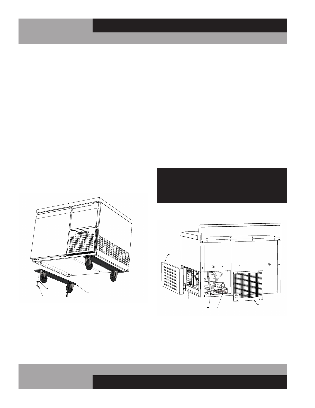
20
REFRIGERATED BASES & PIZZA PREP TABLES
OPERATIONS MANUAL
Check that both plates are secure and that the casters turn
and swivel freely. Carefully lift the cabinet upright and double
check that the caster support plates are secure and the cabinet
is stable. Wait at least 3 hours before turning the refrigeration
system back on, and at least another 30 minutes for the cabinet
to come down to temperature and stabilize, before reloading
with product.
INSTALLING ELECTRIC CONDENSATE HEATER
The condensate heater has a thermal limit switch and power
cord attached. Remove the screws for the rear access panel
from the cabinet and set aside. Place the condensate heater in
the drain pan as shown in Figure 17. Position the end of the
plastic drain tube in the pan. Make sure tubing isn’t kinked, is
secure and doesn’t touch the heater. Plug the heater power cord
into the receptacle labeled “vaporizer”. Secure excess cord with
a wire tie, so it doesn’t fall into the pan or under the cabinet.
Reattach the access panel to the back of the cabinet.
IMPORTANT NOTE: It is extremely important to ensure
the condensate heater is plugged into the receptacle
labeled “vaporizer” and that the condensing unit is
plugged into the receptacle labeled “condensing unit.”
DIAL THERMOMETER AND CALIBRATION
Your NSF-approved dial thermometer has a remote sensing
bulb, located in the refrigerated compartment. The display fea-
tures a large 2” diameter face, with an easy-to-read scale that
shows the internal cabinet temperature in Fahrenheit (°F) and
To install caster support plate assemblies, you will need a 3/4”
open end wrench (or a large adjustable wrench), a drill with a
1/8” bit and a Phillips bit (or a Phillips-Head screwdriver) plus
work gloves. A 1/2-13 thread tap is also recommended, to repair
any damage to the threaded inserts in the cabinet. Unload all
product and carefully lay the cabinet on its back. Remove the old
stem casters by unscrewing them from the cabinet. If a caster or
threaded insert has been stripped or cross-threaded, it may be
necessary to use a wrench to loosen the caster.
Hold one of the support plate assemblies under the cabinet as
shown (see Figure 16). Position it so the slotted holes at the end
of the plate line up with the threaded inserts in the bottom of the
cabinet (where the stem casters were attached). Attach the plate
assembly to the cabinet by putting a 1/2” x 1-3/4” long bolts and
flat washer through the slot in the support plate and screwing
into each of the threaded inserts in the bottom of the cabinet.
Snug the bolts down, but do not tighten them completely. If
one of the threaded inserts is stripped or damaged, a thread tap
should be used to clean the threads.
Using the small holes in the plate as a template, drill 1/8 pilot
holes in the bottom of the cabinet. (Note: drill only until you
penetrate the metal bottom of the cabinet. Do not continue
to drill into the insulation, or you may damage the cabinet.)
Secure the caster support plate assembly to the cabinet with a
sheet metal screw in each of the drilled holes. Tighten the 1/2”
bolts. Repeat these steps to attach the other plate assembly to
the opposite end of the cabinet.
FIGURE 16: Caster Support Plates
FIGURE 17: Electric Condensate Heater
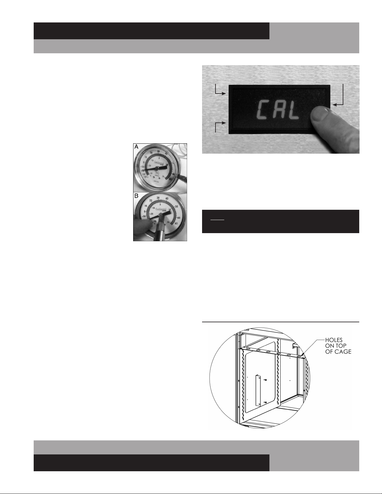
21
OPERATIONS MANUAL
REFRIGERATED BASES & PIZZA PREP TABLES
For example, if the sensing device in the cabinet reads 38° and
the thermometer display reads 40°, press on the lower left cor-
ner twice so that “-2” appears on the display. After adjusting the
offset, press on the right center of the display again to exit cali-
bration mode. Wait 10 to 15 seconds for the cabinet temperature
to be displayed and recheck the calibration.
NOTE: The buttons need to be pressed without delay
between actions. Contact the factory with any questions.
INSTALLING PAN SLIDE CAGE
Place cage in door opening, about 3/4 of the way in. Mount
side bracket(s) in existing holes on interior side(s) or step (see
Figure 18). Mount center bracket in existing holes, on inside of
center mullion, when present (see Figure 18A). After brackets
are installed securely, push cage the rest of the way in. Install 4
screws in front of cage (see Figure 18B). Install angle slide in
desired mounting slots (see Figure 18C).
Celsius (°C). Blue (safe) and red (caution) color bands provide a
quick, visual indication of the temperature inside your refrigera-
tor or freezer. The thermometer is pre-calibrated at the factory,
to accurately show the cabinet temperature.
To check the accuracy of your thermometer, place a pre-cali-
brated temperature sensing device in the center of the refrig-
erated compartment and keep the door closed for at least 10
minutes. The thermometer should read the same temperature
as the sensing device, within +/-2°F
(+/- 1°C). If it does not, use a small
straight-blade screwdriver to care-
fully pry the clear lens cover from the
thermometer body as shown (see
Photo A).
Use a small straight-blade screw-
driver and place on center slotted
hub of thermometer. Carefully hold
the needle and turn the center screw
clockwise to lower and counterclock-
wise to increase the desired tem-
perature, as shown (see Photo B).
Replace the lens cover and recheck
the calibration.
DIGITAL THERMOMETER AND CALIBRATION
Your NSF-approved digital thermometer has a remote sensing
bulb, with an FDA-approved coating, located in the refrigerated
compartment on the left-hand wall. The unit features a large,
easy to read, LED display that shows the internal cabinet tem-
perature.
To check the calibration of your thermometer, place a pre-
calibrated temperature sensing device in the center of the refrig-
erated compartment and keep the door closed for at least 15
minutes. The digital thermometer display should read the same
temperature as the sensing device within +/-2°F (+/- 1°C).
If it does not, press the right, center section of the front display
(see Photo) twice. After the first press, the letters “CAL” will
appear on the screen (to show the unit is in calibration mode).
After the second press, the number of degrees (-25 to 25) that
the display offset is set for will appear. Once you see this, press
on the lower left corner of the front face to decrease the tem-
perature displayed, or press on the upper left section to increase
the temperature displayed.
Press here to decrease temp.
Press here for
calibration modePress here to increase temp.
FIGURE 18: Pan Slide Cage Side Bracket(s)
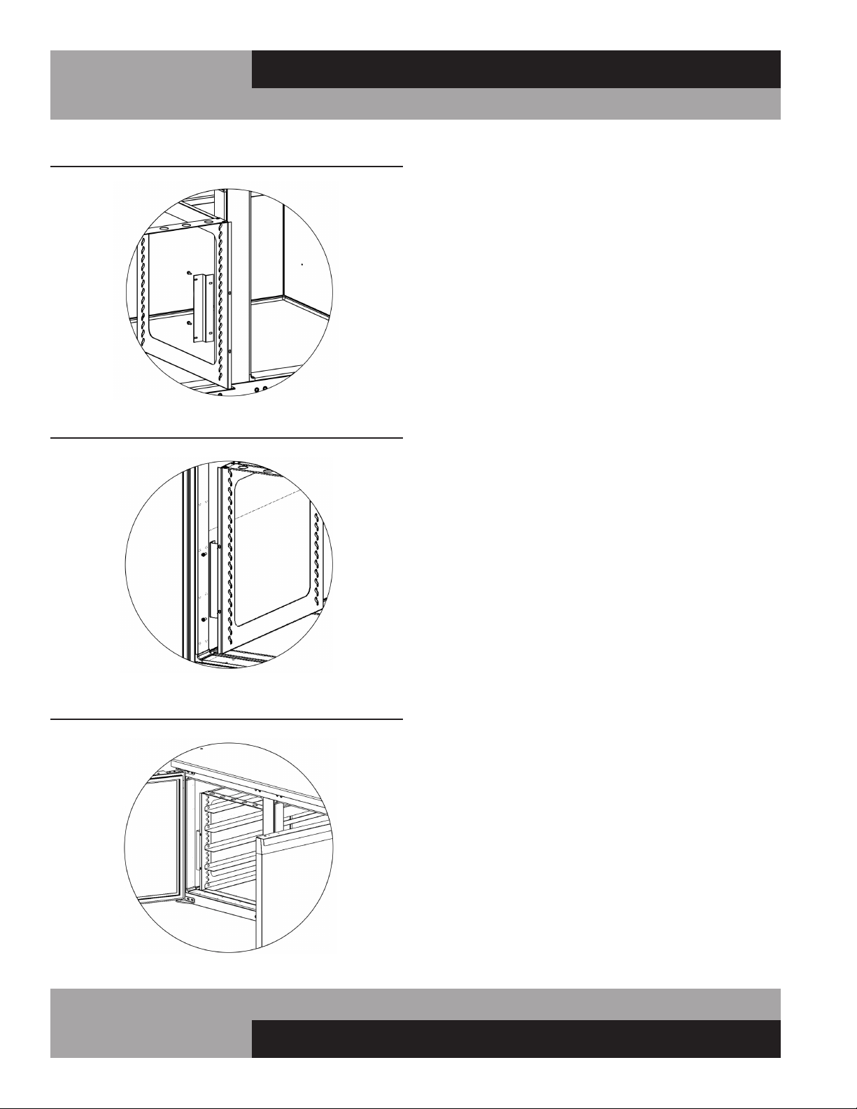
22
REFRIGERATED BASES & PIZZA PREP TABLES
OPERATIONS MANUAL
REMOTE SET-UP AND INSTALLATION GUIDELINES
All remote refrigerators and freezers are shipped with an expan-
sion valve, thermostat and defrost timer (freezer only), installed
from the factory. The installer is responsible for connecting all
refrigerant lines, liquid line drier, sight glass, solenoid, head
pressure control, hi/low pressure safety, crankcase heater, con-
densing unit and any other accessories as well as wiring. The
evaporator section has been factory leak checked with helium,
however; due to vibration in transit, the entire system must be
thoroughly leak checked after installation and prior to start-up.
The final leak inspection of the entire completed refrigeration
system and all of its components as well as start-up and the
operation of the refrigeration system is the sole responsibility
of the installer.
The CFC-Free refrigerant used in standard remote and self-
contained models is R-134a for refrigerators and R-404A for
freezers. All compressors and systems designed for these
refrigerants utilize polyolester oil as their main lubricant, which
absorbs moisture from the ambient surroundings extremely fast
and in much greater quantity than conventional mineral oils.
Since moisture levels greater than 100 PPM will result in system
corrosion and ultimate failure, it is imperative that the compres-
sor, components and entire system be kept sealed.
1. All refrigerant lines and components must be clean, free of
burrs and purged with nitrogen prior to and during brazing
or soldering connections. Nitrogen purging during braz-
ing or soldering will eliminate carbon or foreign matter
contamination. Any system restrictions or contamination is
the responsibility of the installer.
2. Condensing unit or compressor shall not be left open to
the atmosphere for more than five (5) minutes.
3. No refrigeration component, tubing or fitting shall be left
open to the atmosphere for more than ½ hour without
being soldered, capped or plugged.
4. Each completed refrigeration system shall be purged with
150psi of dry nitrogen for at least six (6) seconds, then
pressurized with at least 165psi of nitrogen for pressure
check (making sure to energize any solenoid valves to
assure access). Leak-check all joints, flare fittings and
valves and make sure there is no pressure drop within the
system.
5. System evacuation is of the utmost importance with NON-
CFC refrigerant systems. System must be evacuated to a
minimum of 200 microns. In addition, a vacuum decay
test is strongly recommended to assure there is not a
large pressure differential between the system and vacuum
pump. System must be evacuated from both high and low
sides of the system using heavy duty vacuum hoses.
FIGURE 18A: Pan Slide Cage - Center Bracket
FIGURE 18B: Pan Slide Cage - Install Screws
FIGURE 18C: Pan Slide Cage - Install Angle Slides
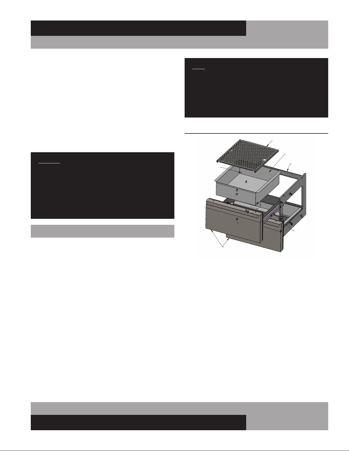
23
OPERATIONS MANUAL
REFRIGERATED BASES & PIZZA PREP TABLES
6. Each system should be charged with the refrigerant type
as specified on the cabinet data tag. This refrigerant type
should match the type listed on the condensing unit being
used. The refrigerant charge should be held to the mini-
mum required for the satisfactory pull down and opera-
tion. For an accurate indication of refrigerant charge, the
sight glass will show a full column of liquid.
7. The superheat reading taken 6” from the compressor suc-
tion valve should be 30° +/- 5°. Expansion valve adjust-
ment may be necessary to achieve this superheat.
8. Installation of the electric condensate heater is the
responsibility of the installer (see “Installing Electric
Condensate Heater” under “Optional Accessories”).
CAUTION: EXTREME CARE MUST BE USED WHEN
ACCESSING THE SYSTEM DURING INSTALLATION. DUE
TO THE COMPLEXITY OF REMOTE REFRIGERATION
SYSTEMS AND THE POTENTIAL FOR IMPROPER
INSTALLATION, ANY RESTRICTIONS, LEAKS, FAILED OR
DAMAGED COMPONENTS CAUSED BY CONTAMINANTS
ARE NOT THE RESPONSIBILITY OF CONTINENTAL
REFRIGERATOR.
FISH FILE BASE MODELS
Fish File models are provided with drawers specially designed
for the storage of fresh fish, or similar product, packed in
crushed ice. Each drawer has a removable pan, with a drain
tube at the back corner (see Figure 18). Water from melting ice
in the pan, along with moisture from the product, drains out of
the storage pan through the tube, along a trough on the interior
cabinet wall, down to the sloped interior bottom, and out of the
cabinet through a 1” drain tube.
INSTALLATION AND LOCATION
In addition to normal considerations (see Installation and
Location), Fish File units should be installed directly over a
building floor drain, to rapidly dispose of water from melted ice
that drains out of the cabinet. It is also highly recommended that
your Fish File is located near a water source that can be used to
thoroughly wash down your cabinet regularly.
NOTE: If a building floor drain is not immediately avail-
able, a waste line, with consistent downward slope, must
be supplied and connected to the 1” NPS drain tube
located under the cabinet. An electric condensate vapor-
izer cannot be used to dispose of water from melted ice,
as the liquid waste contains food residue that can cause
unpleasant odors and potentially unsanitary conditions.
FIGURE 18: Fish File Drawer Assembly
CRA FISH FILE DRAWER
MOUNTING
CAGE
GRATE
STORAGE
PAN
DRAIN
TUBE
DRAWER
SLIDE
DRAWER
ASSEMBLY
24
REFRIGERATED BASES & PIZZA PREP TABLES
OPERATIONS MANUAL
PROBLEM PROBABLE CAUSE CORRECTION
Condensing unit will not
start - no hum.
1. Line disconnected, switch open.
2. Fuse removed or blown.
3. Overload protector blown.
4. Control “Off” due to cold location.
5. Control stuck in open position.
6. Wiring improper or loose.
1. Close start or disconnect switch.
2. Replace Fuse.
3. Determine reason and correct/replace.
4. Relocate control.
5. Repair or replace control.
6. Check wiring against diagram.
Condensing unit will not
start - hums but trips on
overload protector.
1. Improperly wired.
2. Low voltage to unit.
3. Starting capacitor defective.
4. Relay failing to close.
5. Compressor motor has a shorted or open
winding.
6. Internal mechanical trouble in compressor.
7. Insufcient air supply.
1. Check wiring against diagram.
2. Determine reason and correct.
3. Determine reason and replace.
4. Determine reason and replace.
5. Replace compressor.
6. Replace compressor.
7. Clear condenser and allow compressor
to cool down.
Condensing unit starts
and runs, but short
cycles on overload
protector.
1. Additional current passing through overload
protector.
2. Low voltage unit.
3. Overload protector defective.
4. Run capacitor defective.
5. Excessive discharge pressure.
6. Excessive suction pressure.
7. Insufcient air supply.
1. Check wire diagram. Check for added
components connected to wrong side of
overload protector.
2. Determine reason and correct.
3. Check current, replace protector.
4. Determine reason and replace.
5. Check ventilation, restrictions in cooling
medium or refrig. system.
6. Check for misapplication.
7. Clear condenser and allow compressor
to cool down.
Condensing unit starts,
but fails to switch off of
“start” winding.
1. Improperly wired.
2. Low voltage to unit.
3. Relay failing to open.
4. Run capacitor defective.
5. Excessively high discharge pressure.
6. Compressor motor has a shorted or open
winding.
7. Internal mechanical trouble in compressor.
1. Check wiring against diagram.
2. Determine reason and correct.
3. Determine reason and replace.
4. Determine reason and replace.
5. Check discharge shut-off valve, possible
overcharge.
6. Replace compressor.
7. Replace compressor.
Condensing unit runs,
but short cycles on:
1. Overload protector.
2. Thermostat.
3. High pressure cut-out due to:
(a) Insufcient air supply.
(b) Overcharge.
(c) Air in system.
4. Low pressure cut-out due to:
(a) Valve leak.
(b) Undercharge.
(c) Restriction in expansion device.
1. See Problem 3
2. Differential must be widened.
3.
(a) Check air supply to condenser.
(b) Evacuate and re-charge.
(c) Evacuate and re-charge.
4.
(a) Replace, evacuate and re-charge.
(b) Evacuate and re-charge.
(c) Replace expansion device.
Condensing unit runs,
but for prolonged peri-
ods or continuous.
1. Shortage of refrigerant.
2. Control contacts stuck closed.
3. Excessive heat load placed into cabinet.
4. Prolonged or too frequent door openings.
5. Evaporator coil iced.
6. Restriction in refrigeration system.
7. Dirty condenser.
8. Filter drier clogged.
1. Fix leak, evacuate and re-charge.
2. Clean contacts or replace control.
3. Allow unit sufcient time for removal of latent
heat.
4. Plan or organize schedule to correct condition.
5. Defrost evaporator coil.
6. Determine location and remove.
7. Clean condenser coil.
8. Replace, evacuate and re-charge.
TROUBLESHOOTING GUIDE
25
OPERATIONS MANUAL
REFRIGERATED BASES & PIZZA PREP TABLES
TROUBLESHOOTING GUIDE
PROBLEM PROBABLE CAUSE CORRECTION
Start capacitor open,
shorted or blown.
1. Relay contact not opening properly.
2. Prolonged operation on start cycle:
(a) Low voltage to unit.
(b) Improper relay.
(c) Starting load too high.
3. Excessive short cycling.
4. Improper capacitor.
1. Clean contacts or replace relay.
2.
(a) Determine reason and correct.
(b) Replace with correct relay.
(c) Correct by using pump down.
3. Determine reason for short cycle, see Problem
5 and correct.
4. Determine correct size and replace.
Run capacitor open,
shorted or blown.
1. Improper capacitor.
2. Excessively high line voltage, over 110%
of rated maximum.
1. Check size and replace.
2. Determine reason and correct.
Relay defective or blown
out.
1. Incorrect Relay.
2. Incorrect mounting angle.
3. Voltage too low or too high.
4. Excessive short cycling.
5. Loose or vibrating mounting position.
6. Incorrect run capacitor.
7. Loose wiring on relay or overload.
1. Check relay and replace.
2. Remount relay in correct position.
3. Determine reason and correct.
4. Determine reason and correct (see Problem 5).
5. Remount rigidly.
6. Replace with proper capacitor.
7. Tighten all wiring screws.
Product zone
temperature too high.
1. Control setting too high.
2. Inadequate air circulation.
3. Dirty condenser.
1. Adjust T-stat.
2. Rearrange product load to improve air
circulation.
3. Clean condenser coil.
Suction line frosted or
sweating.
1. Overcharge of refrigerant.
2. Evaporator fan not running.
3. Expansion valve stuck open.
4. Expansion valve superheat too low.
1. Evacuate and re-charge.
2. Determine reason and correct.
3. Clean valve, evacuate and re-charge.
4. Adjust superheat to required setting.
Liquid line frosted, cold
or sweating.
1. Restriction in drier strainer.
2. Liquid line service valve partially closed.
1. Replace drier, evacuate and re-charge.
2. Open valve fully or replace if necessary.
Noisy condensing unit. 1. Loose parts or mounting.
2. Tubing rattle or vibration.
3. Bent fan blade causing excessive vibration.
4. Fan bearings worn.
1. Tighten all mounting parts and shroud cover.
2. Reform tubing to be free of contact.
3. Replace fan blade.
4. Replace fan motor.
Thermometer reads
different than actual
temperature.
1. Calibration.
2. Defective.
1. Consult Operations Manual and calibrate.
2. Replace.
Water leak inside unit. 1. Condensate drain pan not installed properly.
2. Unit not level.
3. Drain pan misaligned.
4. Defective drain pan.
1. Consult Operations Manual for install
instructions.
2. Make sure unit is level or pitched back slightly.
3. Make sure drain pan is aligned properly.
4. Replace.
Doors misaligned. 1. Shifted during shipping. 1. Refer to Operation Manual for hinge
adjustment.
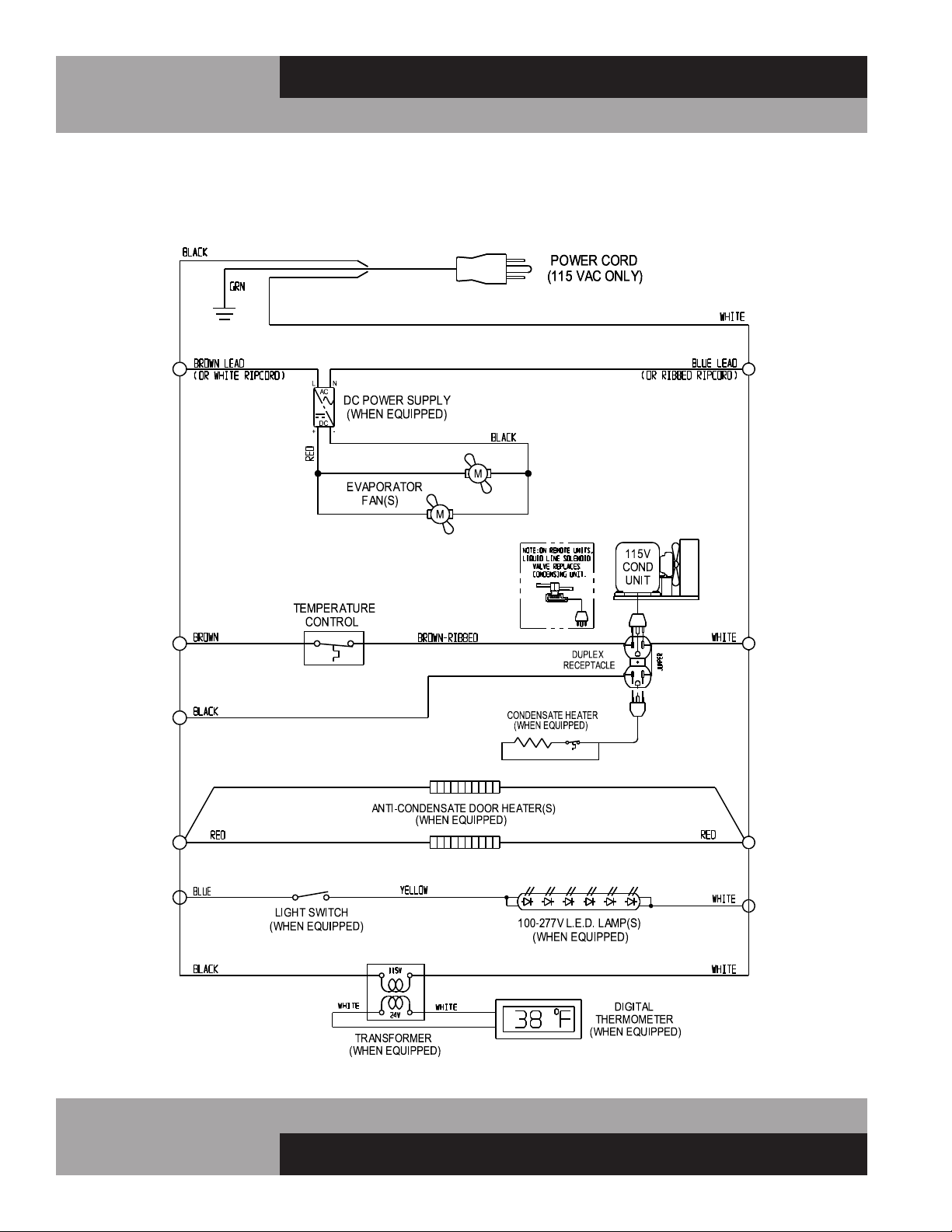
26
REFRIGERATED BASES & PIZZA PREP TABLES
OPERATIONS MANUAL
BASE WORKTOP & SANDWICH UNIT REFRIGERATORS 115/60/1
WD-R5 WIRING DIAGRAM
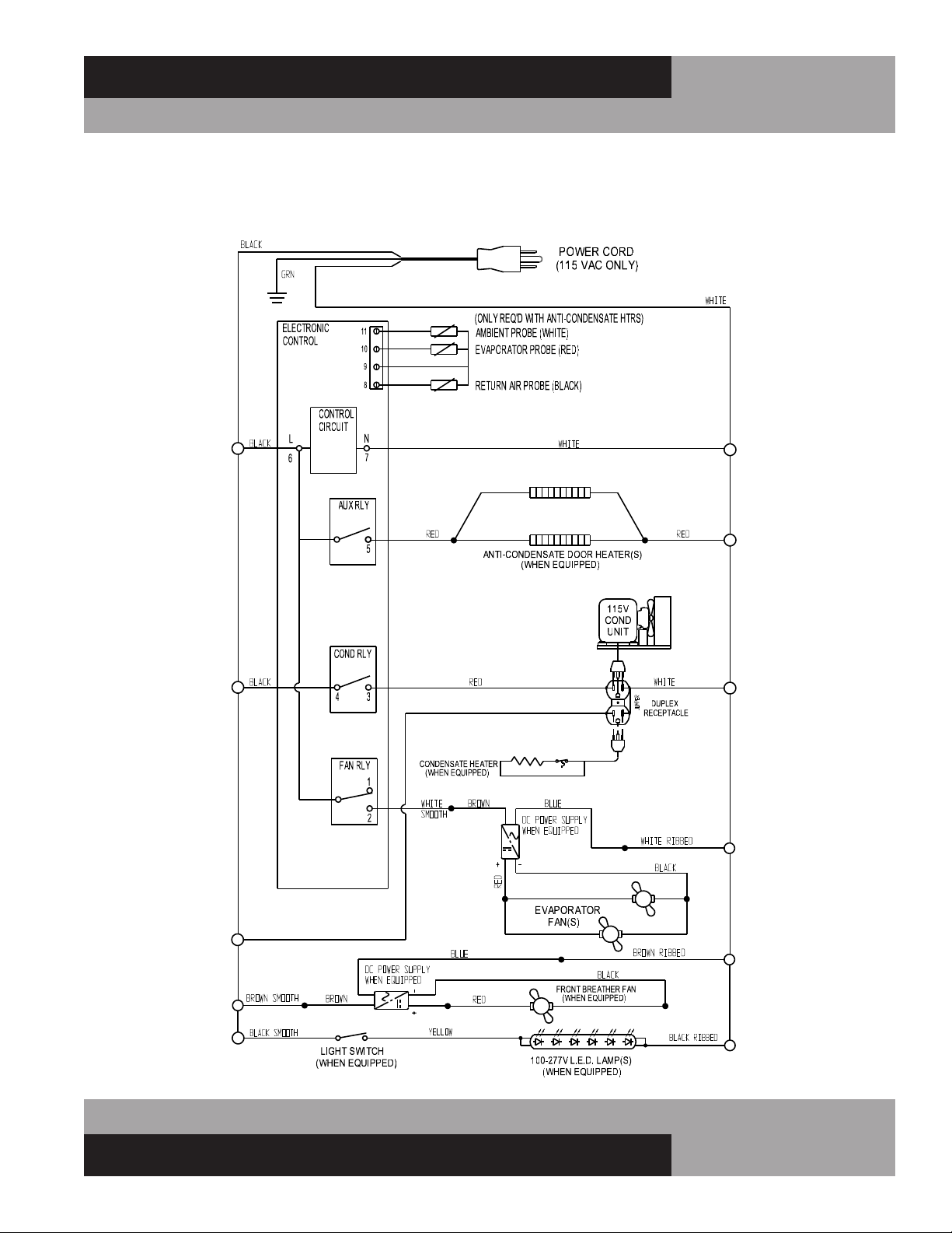
27
OPERATIONS MANUAL
REFRIGERATED BASES & PIZZA PREP TABLES
BASE WORKTOP/SANDWICH UNIT/PIZZA PREP REFRIGERATORS 115/60/1
W/ ELECTRONIC CONTROL WD-R5-EC WIRING DIAGRAM
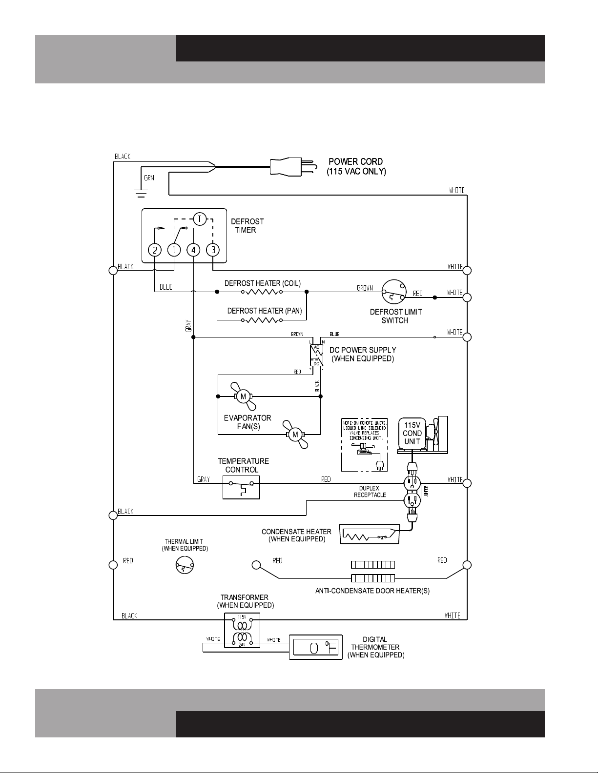
28
REFRIGERATED BASES & PIZZA PREP TABLES
OPERATIONS MANUAL
BASE WORKTOP FREEZER 115/60/1
WD-F5 WIRING DIAGRAM
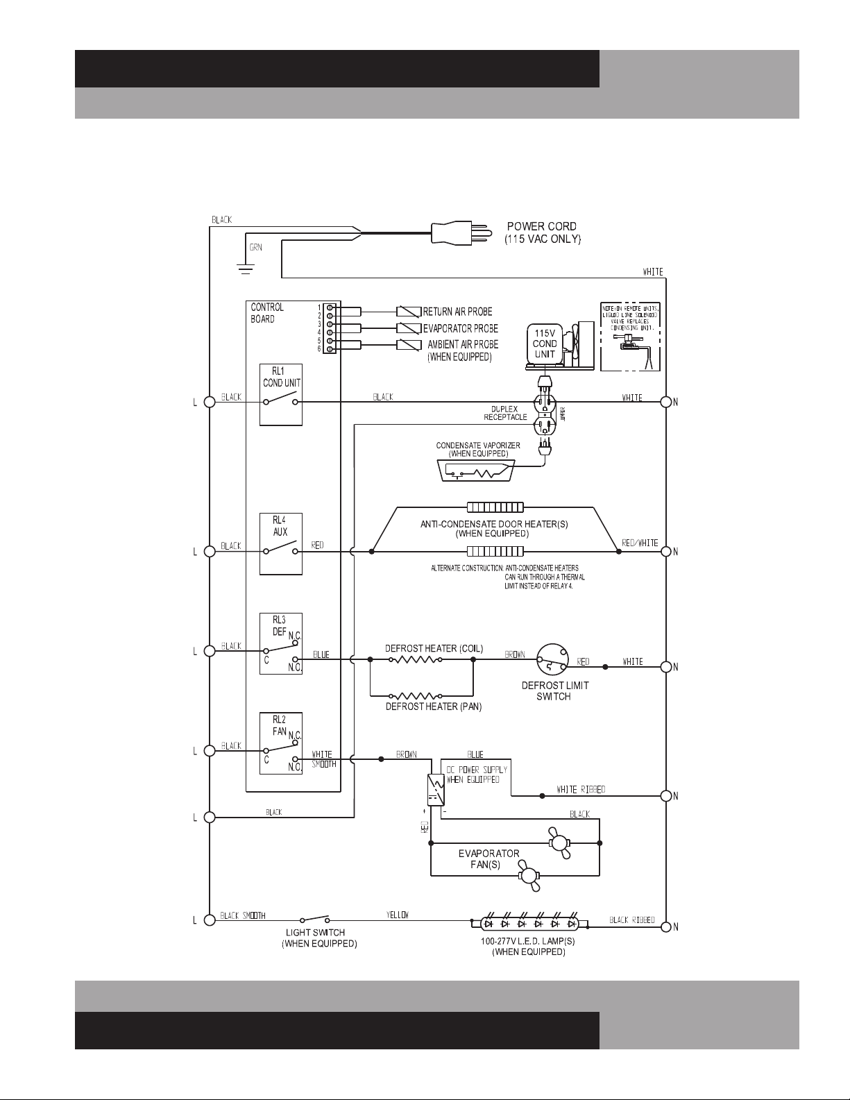
29
OPERATIONS MANUAL
REFRIGERATED BASES & PIZZA PREP TABLES
BASE WORKTOP FREEZER 115/60/1
W/ SPLIT ELECTRONIC CONTROL WD-F5-EC-SP WIRING DIAGRAM

30
REFRIGERATED BASES & PIZZA PREP TABLES
OPERATIONS MANUAL
WARRANTY United States of America & Canada
THREE (3) YEAR PARTS AND LABOR WARRANTY
Continental Refrigerator warrants to the original purchaser of every new Continental Refrigerator self contained unit, including all parts thereof, that such equipment is
free from defects in material and workmanship, under normal use, proper maintenance and service as indicated by Continental Refrigerator installation and operation
manual, for a period of three (3) years from the date of installation, or thirty-nine (39) months from the date of shipment from the manufacturer, whichever comes
rst. Normal wear type parts, such as light bulbs/lamps and gaskets are not covered by this warranty. For the purpose of this warranty, the original purchaser shall be
deemed to mean the individual or company for whom the product was originally installed.
Continental Refrigerators obligation under this warranty shall be limited to repairing or replacing, including labor, any part of such product which proves thus defective.
Continental Refrigerator reserves the right to examine any product claimed to be defective. The labor warranty shall be for self-contained units only and for standard
straight time, which is dened as normal service rate time, for service performed during normal working hours. Any service requested outside of a servicer’s normal
working hours will be covered under this warranty for the normal rate and any additional overtime rate will be the responsibility of the equipment purchaser.
Any part determined to be defective in the product should be returned to the company within thirty (30) days under the terms of this warranty and must be accompanied
by the cabinet model, serial number, and identied with a return material authorization number, issued by the manufacturer.
Special installation/applications, including remote locations, are limited in coverage by this warranty. Any installation that requires extra work, and/or travel, to gain
access to the unit for service is the sole responsibility of the equipment purchaser.
Improper operation resulting from factors, including but not limited to, improper or negligent cleaning and maintenance, low voltage conditions, inadequate wiring, and
accidental damage are not manufacturing defects and are strictly the responsibility of the purchaser.
Condenser coils must be cleaned at regular intervals. Failure to do so can cause compressor malfunction and will void warranty. Continental Refrigerator recommends
a minimum monthly cleaning, as stated in the installation and operation manual.
ADDITIONAL TWO (2) YEAR COMPRESSOR PART WARRANTY
In addition to the warranty set forth above, Continental Refrigerator warrants the hermetically/semi-hermetically sealed compressor (part only) for an additional two (2)
years beyond the rst three (3) year warranty period; not to exceed sixty-three (63) months from the date of shipment from Continental Refrigerator, provided upon
receipt of the compressor, manufacturer examination shows the sealed compressor to be defective. This extended warranty does not cover freight for the replacement
compressor or freight for return of the failed compressor. Also, this extended compressor-part only warranty does not apply to any electrical controls, condenser,
evaporator, fan motors, overload switch, starting relay, capacitors, temperature control, lter/drier, accumulator, refrigeration tubing, wiring harness, labor charges, or
supplies which are covered by the standard warranty above.
THE FOREGOING WARRANTIES ARE EXPRESSLY GIVEN IN LIEU OF ALL OTHER WARRANTIES, EXPRESS, IMPLIED, OR STATUTORY, INCLUDING THE IMPLIED
WARRANTIES OF MERCHANTABILITY AND FITNESS FOR A PARTICULAR PURPOSE, WHICH ARE HEREBY DISCLAIMED, ALONG WITH ALL OTHER OBLIGATIONS OR
LIABILITIES ON OUR PART. AND WE NEITHER ASSUME, NOR AUTHORIZE ANY OTHER PERSON TO ASSUME FOR US, ANY OBLIGATION OR LIABILITY IN CONNEC-
TION WITH THE SALE OF SAID REFRIGERATION UNITS OR ANY PARTS THEREOF.
This warranty shall not be assignable and shall be honored only in so far as the original purchaser.
This warranty does not apply outside the limits of the United States of America and Canada, nor does it apply to any part that has been subject to misuse, neglect,
alteration, accident, or to any damage caused by transportation, ood, re, acts of terrorism, or acts of God.
IN NO EVENT SHALL CONTINENTAL REFRIGERATOR BE LIABLE FOR CONSEQUENTIAL, SPECIAL OR PUNITIVE DAMAGES. THE REMEDIES OF PURCHASER SET
FORTH HEREIN ARE EXCLUSIVE AND THE TOTAL LIABILITY OF CONTINENTAL REFRIGERATOR, WHETHER BASED ON CONTRACT, WARRANTY, NEGLIGENCE, IN-
DEMNIFICATION, STRICT LIABILITY, TORT, OR OTHERWISE, SHALL NOT EXCEED THE PURCHASE PRICE OF THE COMPONENT UPON WHICH LIABILITY IS BASED.
CONTINENTAL REFRIGERATOR SHALL HAVE NO OBLIGATION OR LIABILITY FOR CONSEQUENTIAL OR SPECIAL DAMAGES, INCLUDING BUT NOT LIMITED TO
INDIRECT, PUNITIVE DAMAGES, LOSS OF USE, LOSS OF PRODUCT, DOWNTIME OR LOST PROFITS, ARISING OUT OR, RELATED TO OR CONNECTED IN ANY WAY
WITH THE PRODUCT OR ITS USE.
A Division of National Refrigeration & Air Conditioning Products, Inc.
539 Dunksferry Road • Bensalem, PA 19020-5908
P 215-244-1400 • 1-800-523-7138 • F 215-244-9579
www.continentalrefrigerator.com


A Division of National Refrigeration & Air Conditioning Products, Inc.
539 Dunksferry Road • Bensalem, PA 19020-5908
P 215-244-1400 • 1-800-523-7138 • F 215-244-9579
www.continentalrefrigerator.com
IM-CPA-CRA-Red-50196-20191111
®