OWNER’S USE AND CARE GUIDE
GUIDE D’UTILISATION ET D'ENTRETIEN
MODEL • MODÈLE
DANBY PRODUCTS LIMITED, ONTARIO, CANADA N1H 6Z9
DANBY PRODUCTS INC., FINDLAY, OHIO, USA 45840
PORTABLE AIR CONDITIONER
CLIMATISEUR PORTATIF
DPA120HCB1WDB / DPA120HUB1WDB
31.10.14

DO NOT RETURN THIS UNIT TO THE RETAILER
WITHOUT FURTHER INSTRUCTIONS
Dear valued customer, we hope your Danby product purchase fulfills all
your requirements. Your satisfaction is our priority!
Please contact us at our toll free consumer service number for any inquiries
you may have about your new unit.
NE PAS RETOURNER CET APPAREIL CHEZ LE
DÉTAILLANT SANS CONSIGNES SUPPLÉMENTAIRES
Cher(ère) client(e) important(e), nous espérons que votre produit Danby
répond à tous vos besoins. Votre satisfaction est notre priorité!
Veuillez nous contacter au numéro gratuit de service après-vente, si
vous avez des questions quelconques à propos de votre nouvel appareil.
NO DEVUELVA ESTA UNIDAD A LA TIENDA SIN
INSTRUCCIONES ADICIONALES
Estimado cliente, esperamos que el producto Danby que ha comprado
satisfaga completamente sus necesidades. Su satisfacción
es nuestra prioridad!
Por favor, contáctenos gratuitamente a nuestro número de Servicio al
Cliente para cualquier pregunta que tenga sobre su nuevo electrodoméstico.
1-800-263-2629
(1-800-26-DANBY)
Danby 28.08.2014
TO OBTAIN WARRANTY SERVICE YOU MUST PROVIDE A VALID PROOF OF
PURCHASE. PLEASE STAPLE YOUR RECEIPT TO THIS PAGE FOR FUTURE
REFERENCE.
POUR OBTENIR LE SERVICE SUR GARANTIE, VOUS DEVEZ FOURNIR UNE
PREUVE D’ACHAT VALIDE. VEUILLEZ AGRAFER VOTRE REÇU À CETTE PAGE
POUR RÉFÉRENCE FUTURE.
This product is factory equipped with a power supply cord that has a three-pronged grounded plug. It must
be plugged into a mating grounding type receptacle in accordance with the National Electrical Code and
applicable local codes and ordinances. If the circuit does not have a grounding type receptacle, it is the
responsibility and obligation of the customer to exchange the existing receptacle in accordance with the
National Electrical Code and applicable local codes and ordinances. The third ground prong should not,
under any circumstances, be cut or removed. Never use the cord, the plug or the appliance when they show
any sign of damage. Do not use your appliance with an extension cord unless it has been checked and test-
ed by a qualifi ed electrician or electrical supplier.
IMPORTANT - GROUNDING METHOD
Ce produit arrive d’origine avec un cordon d’alimentation équipé d’une prise à trois fi ches. Il doit être
branché dans une prise avec une fi che de mise à la terre en conformité avec le Code national de l’électricité
et les codes et règles locaux applicables. Si la prise murale n’a pas de mise à la terre, il est de la
responsabilité du client de changer la prise existante pour la rendre conforme au Code national de
l’électricité et aux codes et règles locaux applicables. La fi che de mise à la terre ne doit pas, en aucune
circonstance, être coupée ou retirée. Si vous apercevez des signes de dommage, n’utilisez jamais le cordon
d’alimentation, la prise ou l’appareil. N’utilisez jamais l’appareil avec une rallonge sauf si elle a été vérifi ée et
testée par un électricien qualifi é ou un fournisseur de matériel électrique.
IMPORTANT - MÉTHODE POUR LA MISE À LA TERRE
PORTABLE AIR CONDITIONER
Owner’s Use and Care Guide ................................
• Welcome
• Important Safety Information
• Features
• Installation Instructions
• Operation Instructions
• Care and Maintenance
• Troubleshooting
• Warranty
CLIMATISEUR PORTATIF
Guide d’utilisation et d’entretien............................
• Bienvenue
• Consignes de sécurité importantes
• Caractéristiques
• Consignes d’installation
• Consignes d’utilisation
• Soins et entretien
• Dépannage
• Garantie
CONTENTS
CAUTION:
Read and follow all safety rules and operating
instructions before fi rst use of this product.
AVERTISSEMENT :
Veuillez lire attentivement les consignes de
sécurité et les instructions d’utilisation avant
l’utilisation initiale de ce produit.
TABLE DES MATIÈRES
Model • Modèle
WARNING
Improper connection of the grounding plug can
result in risk of fi re, electric shock and/or injury to
persons associated with the appliance. Check with
a qualifi ed service representative if in doubt that
the appliance is properly grounded.
AVERTISSEMENT
Une fi che de mise à la terre mal branchée peut
entraîner un risque d’incendie, de choc électrique
ou de blessures aux personnes qui utilisent
l’appareil. Si vous n’êtes pas certain que l’appareil
est correctement mis à la terre, consultez un
préposé du service qualifi é.
1-16
17-32
DPA120HCB1WDB / DPA120HUB1WDB
Welcome
Welcome to the Danby family. We are proud of our quality products, and we believe in dependable service, like you will
find in this Owner’s Use and Care Guide, and like you will receive from our friendly customer service department. Best
of all, you will experience these values each and every time you use your Danby appliance. That is important, because
your new appliance will be a part of your family for a long time.
Note the information below; you will need this information to obtain service under warranty.
To receive service, you must provide the original receipt.
Serial
Number:
Date of Purchase:
NEED HELP?
Before you call for service, here are a few things you can do to help
us serve you better:
Read this Owner’s Use and Care Guide:
It contains instructions to help you use and maintain your
appliance properly.
If you received a damaged appliance:
Immediately contact the retailer (or builder) that sold you the
appliance.
Save time and money:
Check the Troubleshooting section at the end of the guide before call-
ing. This section helps you solve common problems that may occur.
If you do need service, you can relax, knowing help is only a phone
call away.
1-800-26-
(1-800-263-2629)
1

Important Safety Information
READ AND FOLLOW ALL SAFETY INSTRUCTIONS
To prevent injury to the user or other people and property damage, the following instructions must be
followed. Incorrect operation resulting from ignoring these instructions may cause harm or damage.
SAFETY
PRECAUTIONS
ALWAYS DO THIS
Your air conditioner should be used in such a way that it is protected from
moisture. e.g. condensation, splashed water, etc. Do not place or store
your air conditioner where it can fall or be pulled into water or any other
liquid. Unplug unit immediately if this occurs.
Always transport your air conditioner in a vertical position and place on a
stable, level surface during use. If the unit is transported laying on its side it
should be stood up and left unplugged for 4 hours.
Turn off the unit when not in use.
Always contact a qualifi ed person to perform repairs. If the power cord is
damaged it must be repaired by a qualifi ed technician.
Keep the unit away from walls, furniture and curtains with a clearance of at
least 30 cm all around.
If the air conditioner is knocked over during use, turn off the unit and
unplug it immediately.
Always use the switch on the control panel to turn the unit on or off.
Portable air conditioners exhaust large amounts of room air. Always ensure
an adequate supply of make-up air to operate effi ciently.
NEVER DO THIS
Do not operate your air conditioner in a wet room such as a bathroom or
laundry room.
Do not touch the unit with wet or damp hands.
Do not press the buttons on the control panel with anything other than your
fi ngers.
Do not remove any fi xed components. Never use this appliance if it is not
working properly, or if it has been dropped or damaged.
Never use the plug to start and stop the unit.
Do not cover or obstruct the inlet or outlet grilles.
Do not use hazardous chemicals to clean or come into contact with the unit.
Do not use the unit in the presence of infl ammable substances or vapour
such as alcohol, insecticides, gasoline, etc.
Do not allow children to operate the unit unsupervised.
Do not use this product for functions other than those described in this
instruction manual.
2
Important Safety Information
READ AND FOLLOW ALL SAFETY INSTRUCTIONS
To prevent injury to the user or other people and property damage, the following instructions must be
followed. Incorrect operation resulting from ignoring these instructions may cause harm or damage.
ENERGY SAVING
TIPS
OPERATING
CONDITIONS
TOOLS FOR
WINDOW KIT
INSTALLATION
• Use the unit in the recommended room size.
• Locate the unit where furniture cannot obstruct the air fl ow.
• Keep blinds/curtains closed during the sunniest part of the day.
• Keep the fi lters clean.
• Keep doors and windows closed to keep cool air in and warm air out
(cooling mode)
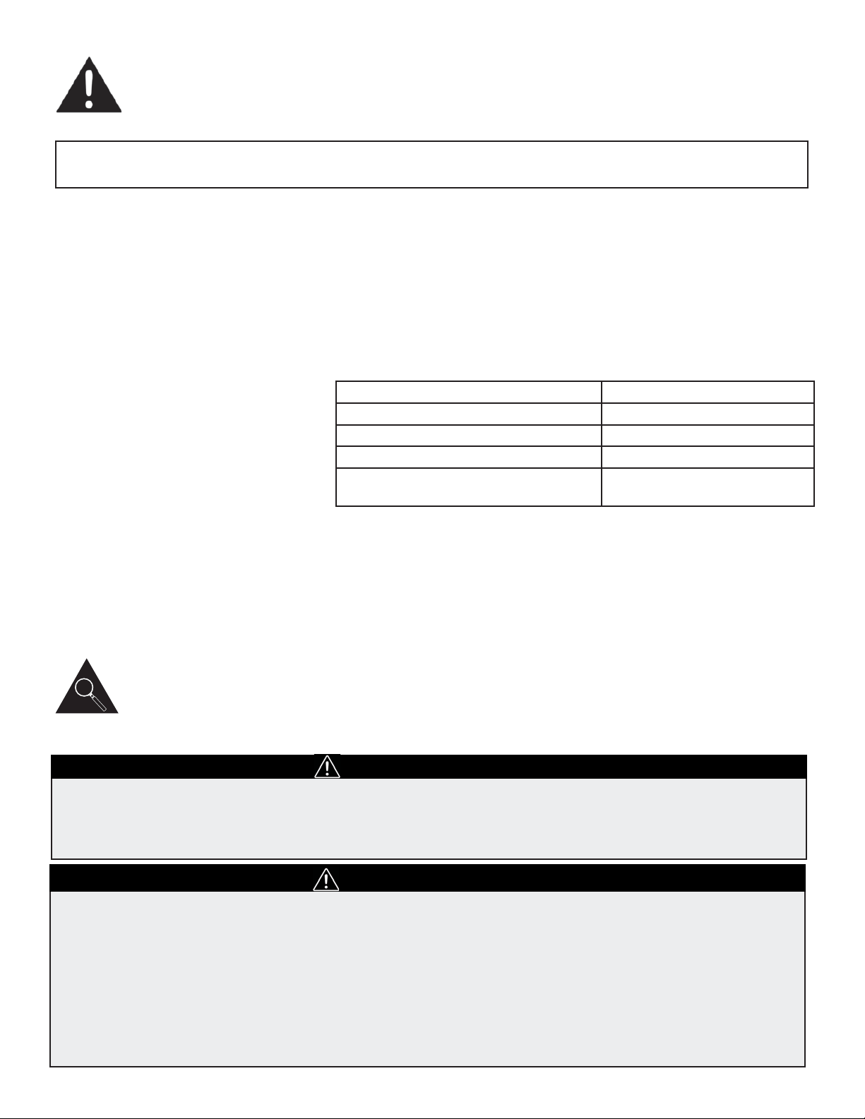
The air conditioner must be operated within the temperature range
indicated below:
Note: Performance may be reduced outside of these operating tempera-
tures.
1. Screwdriver (medium size, Phillips)
2. Tape measure or ruler
3. Knife or scissors
4. Saw (In the event that the window kit needs to be cut down in size
because the window is too narrow for direct installation).
See www.danby.com for general instruction guide
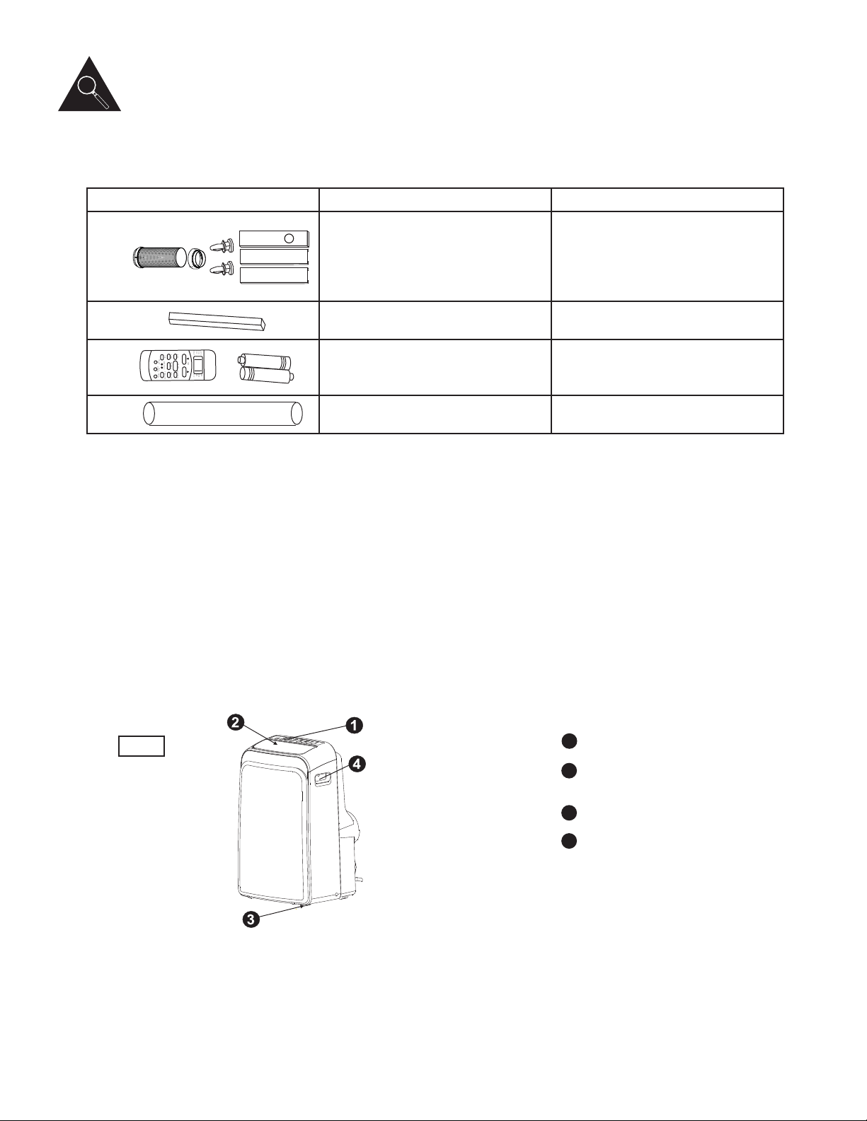
Identifying Parts
WARNING
• Do not store or use gasoline or other fl ammable vapours and liquids in the vicinity of this or any other
appliance.
• Avoid fi re hazard or electric shock. Do not use an extension cord or an adaptor plug. Do not remove any
prong from the power cord.
ELECTRICAL INFORMATION
WARNING
• Be sure the electrical supply is adequate for the model you have chosen. This information can be found
on the serial plate, which is located on the side of the cabinet and behind the grill.
• Be sure the air conditioner is properly grounded. To minimize shock and fi re hazards, proper grounding
is important. The power cord is equipped with a three-prong grounding plug for protection against
shock hazards.
• Your air conditioner must be used in a properly grounded wall receptacle. If the wall receptacle you
intend to use is not adequately grounded or protected by a time delay fuse or circuit breaker, have a
qualifi ed electrician install the proper receptacle.
• Ensure the receptacle remains accessible after the unit is installed.
3
MODE ROOM TEMPERATURE
COOL 17°C (62°F) ~ 35°C (95°F)
DRY 13°C (55°F) ~ 35°C (95°F)
HEAT (heat pump type) 5°C (41°F) ~ 30°C (86°F)
HEAT (electrical or heat pump) <30°C / 86 °F
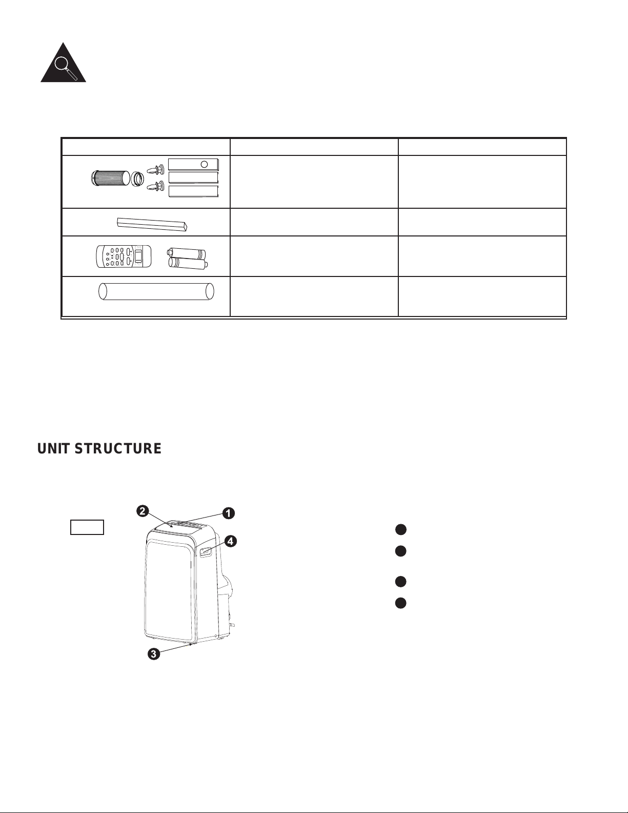
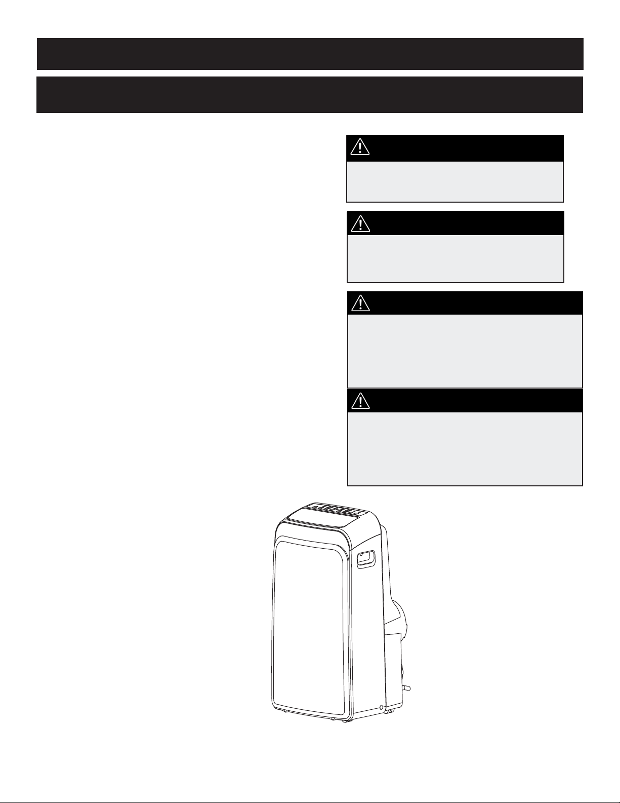
FRONT
1
2
3
4
Control Panel
Horizontal louver blade
(adjusts automatically)
Caster
Carrying handle
(both sides)
Fig.1
4
Identifying Parts
ACCESSOIRES
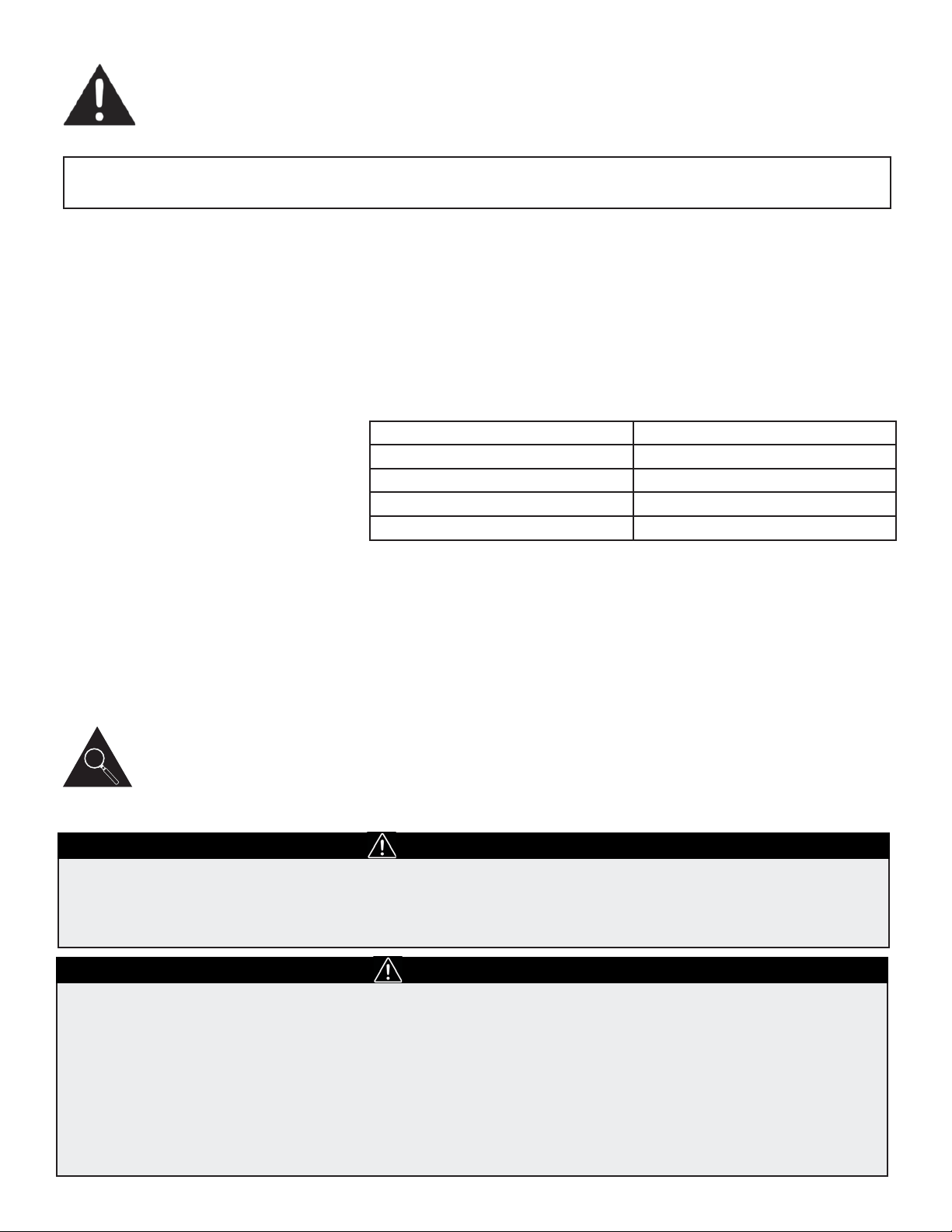
PARTS PART NAME QUANTITY
Exhaust hose and adapotor;
window slider kit and pins
1 set
Foam seal 6 pieces
Remote controller and battery
(for remote control models only)
1 ensemble
Drain hose and drain adaptor* 1 piece
• Check all the accessories are included in the package and please refer to the installation instructions for
their usage.
NOTE: All the illustrations in this manual are for explanation purpose only. Your air conditioner may be slightly
different.
NOTE: Optional parts (*), some models do include
P
M
ET
O
T
U
A
L
OO
C
R
D
Y
E
H
T
A
F
N
A
H
G
IH
D
E
M
O
L
W
EDOM
F
DE
E
P
S
N
A
G
N
IWS
N
O
REMI
T
Y
MO
NOCE
FF
O/
N
O
F
FORE
M
I
T
RE
SE
T
L
OC
K
W
O
L
L
O
F
E
M
D
E
L
Y
A
L
P
S
I
D
N
O
I
O
B
RUT
UNIT STRUCTURE
Identifying Parts
Features
ELECTRONIC CONTROL
INSTRUCTIONS
Before you begin, thoroughly familiarize yourself with the control pannel and remote controller and all its functions. Select
the functions you desire based on the associated symbol.
The unit can be controlled by the control panel alone or with the remote controller.
Note: This manual does not include Remote Controller Operation. See the Remote Controller Instructions packed with the
unit for this information.
5
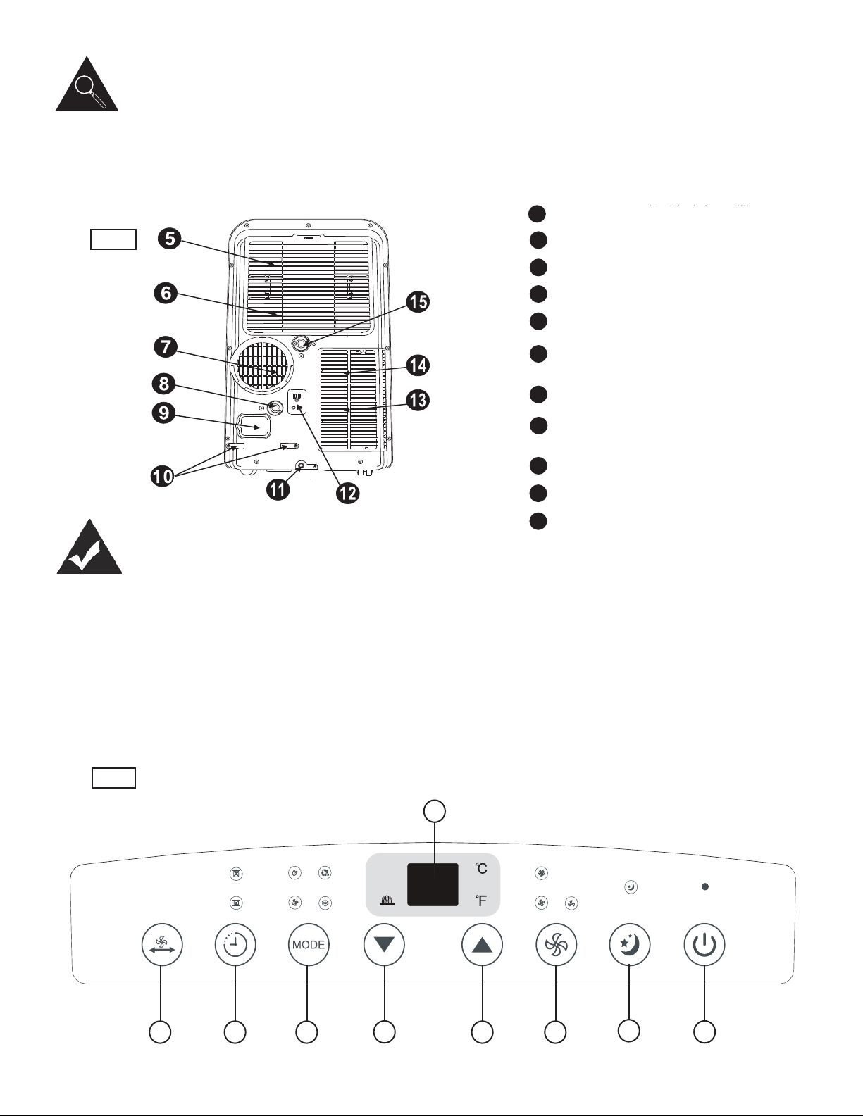
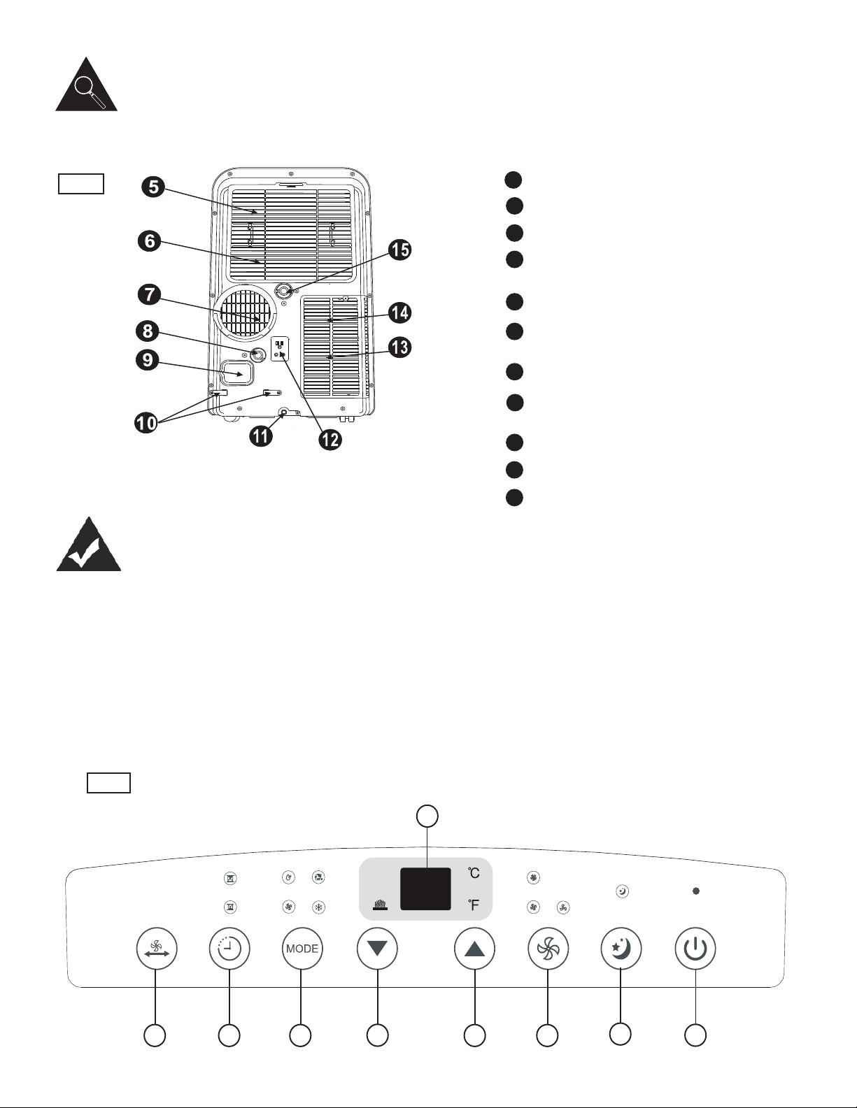
REAR
6
7
8
9
10
11
12
13
Upper air filter (Behind the grill)
Upper air intake
Air outlet
Drain outlet (only for pump heating model)
Power cord outlet
Power cord buckle (used only when storing
the unit)
Bottom tray drain outlet
Power plug socket (use only when storing
the unit)
Lower air filter (behind the grill)
Lower air intake
Drain outlet
Fig.2
5
14
15
Fig.3
1
2
34
4
567
8
(behind the grill)

Features
ELECTRONIC CONTROL
INSTRUCTIONS
6
POWER button
Turns power on/off.
SLEEP button
Used to initiate the SLEEP operation.
FAN button
Controls the fan speed. Press to toggle between three fan
speeds: LOW (press 1 time), MEDIUM (press 2 times) and
HIGH (press 3 times). The fan speed indicator light indicates
the corresponding fan setting. Press the button a fourth time to
initiate AUTO-FAN mode. In this mode, all three indicator lights
will light up.
UP and DOWN buttons
Used to adjust (increase / decrease) temperature settings
(1°C/1°F increments) in a range of 17°C(62°F) to 30°C(86°F)
or the TIMER setting in a range of 0~24hrs. The control is
capable of displaying temperature in degrees Fahrenheit or
degrees Celsius. To convert from one to the other, press and
hold the Up and Down buttons at the same time for 3 seconds.
MODE select button
Selects the appropriate operating mode. Each time you press
the button, a mode is selected in a sequence that goes from
AUTO, COOL, DRY, FAN and HEAT. The mode indicator light
illuminates depending on the mode settings.
TIMER button
Used to initiate the AUTO ON start time and AUTO OFF stop time program,
in conjunction with the up & down buttons.
SWING button
(select models only) Used to initiate the Auto swing feature. When
operating press the SWING button to stop the louver at the desired angle.
LED DISPLAY
Shows the set temperature in °C or °F and the Auto-timer settings.
While on DRY and FAN modes, it shows the room temperature.
Error codes:
E1 - Room temperature sensor error -Unplug the unit and plug
it back in. If error repeats, call for service.
E2 - Evaporator temperature sensor error- Unplug the unit and
plug it back in. If error repeats, call for service.
E3 - Condenser temperature error - Unplug the unit and plug it
back in. If error repeats call for service.
E4 - Display panel communication error - Unplug the unit and
plug it back in. If error repeats call for service.
P1 - Bottom tray is full - Connect the drain hose and drain the
collected water away. If error repeats, call for service.
1
2
3
4
5
6
7
8

Operating Instructions
OPERATING MODES
7
COOL mode
- Press the “MODE” button until the “COOL” indicator light comes on.
- Press the UP or DOWN arrow buttons to select your desired
room temperature. The temperature can be set within a range of
17°C-30°C / 62°F-86°F.
- Press the “FAN SPEED” button to choose the fan speed.
AUTO mode
- When you set the air conditioner in AUTO mode, it will automatically select cool-
ing, or fan only operation depending on what temperature you have selected and
the room temperature.
- The air conditioner will adjust the room temperature automatically to the tem-
perature point set by you.
- Under AUTO mode, you can not select the fan speed.
FAN operation
- Press the “MODE” button until the “FAN” indicator light comes on.
- Press the “FAN SPEED” button to choose the fan speed (1 time for LOW,
2 times for MEDIUM, 3 times for HIGH, 4 times for AUTO-FAN).
- The corresponding fan speed indicator light for each speed lights up. All
three indicators are lit up when AUTO-FAN is selected.
- The temperature cannot be adjusted.
- Do not use the window hose in this mode.
TIMER operation
- To initiate the “Auto-stop” program: When the unit is on, press the Timer
button, the TIMER OFF indicator light will illuminate.
- To initiate the “Auto-start” program: When the unit is off, press the Timer
button, the TIMER ON indicator light will illuminate.
- Press or hold the “UP” or “DOWN ” buttons to change the Auto-time by
0.5 hour increments, up to 10 hours, then by 1 hour increments up to 24
hours.The control will count down the time remaining until the unit starts.
- The selected time will register in 5 seconds and the system will
automatically revert back to display the previous temperature setting.
- Turning the unit ON or OFF at any time or adjusting the timer setting
to 0.0 will cancel the Auto Start/Stop timed program.
- When a malfunction (E1,E2,E3, E 4 or P1) occurs, the Auto Start/Stop
timed program will also be cancelled.
SLEEP function
Simply press the sleep button. When in cooling mode, the temperature will
increase by 1°C / 2°F every half hour for 1 hour. The unit will then hold this new
temperature for 7 hours before returning to the original temperature setting and
resuming normal operation.
NOTE: This feature is unavailable in FAN and DRY mode.
HEAT mode
- Press the “MODE” button until the “HEAT” indicator light comes on.
- Press the ADJUST buttons “up” and “down” to select your desired room tem-
perature. The temperature can be set within a range of 17°C-30°C / 62°F-86°F.
- Press the “FAN SPEED” button to choose the fan speed. For some models, the
fan speed cannot be adjusted under HEAT mode.
8
Operating Instructions
POWER OUTAGE
AIR FLOW DIRECTION
ADJUSTMENT
In the case of a power outage or interruption, the unit will automatically re-start with
the default settings after the power is restored.
Wait 3 minutes before resuming operation
After the unit has stopped, it cannot operate for the fi rst 3 minutes. This is to protect
the unit. Operation will automatically start after 3 minutes.
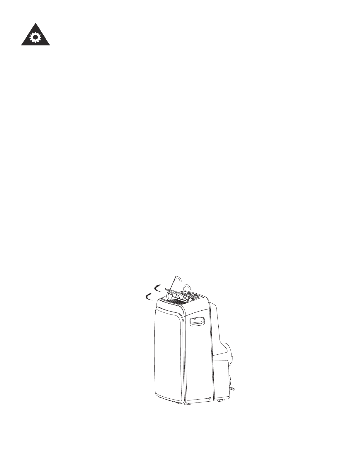
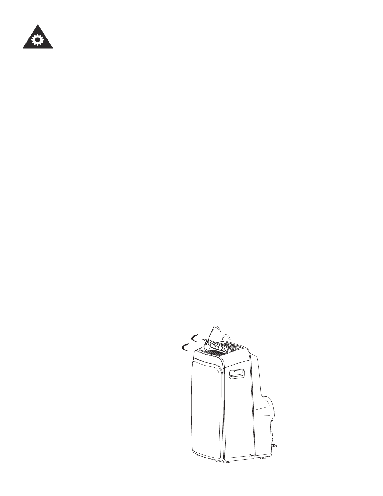
Adjust the air fl ow direction automatically (Fig. 4):
-The louver can be adjusted automatically, to change the airfl ow direction.
-When the power is ON, the louver opens fully.
-Press the SWING button on the panel or remote controller to initiate the Auto
swing feature.
-The louver will swing up and down automatically.
Please do not adjust the louver manually.
Swing automatically
Fig. 4
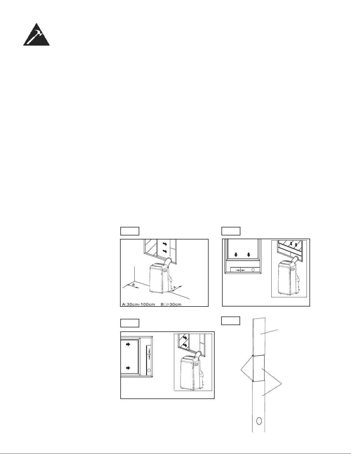
Installation Instructions
LOCATION
• The air conditioner should be placed on a fi rm foundation to minimize noise
and vibration. For safe and secure positioning, place the unit on a smooth, level
fl oor strong enough to support the unit.
• The unit has casters to aid placement, but it should only be rolled on smooth,
fl at surfaces. Use caution when rolling on carpeted surfaces. Use caution and
protect fl oors when rolling over wood fl oors. Do not attempt to roll the unit over
objects.
• The unit must be placed within reach of a properly rated grounded socket.
• Never place any obstacles around the air inlet or outlet of the unit.
• Allow at least 30 cm of space away from the wall for effi cient air conditioning.
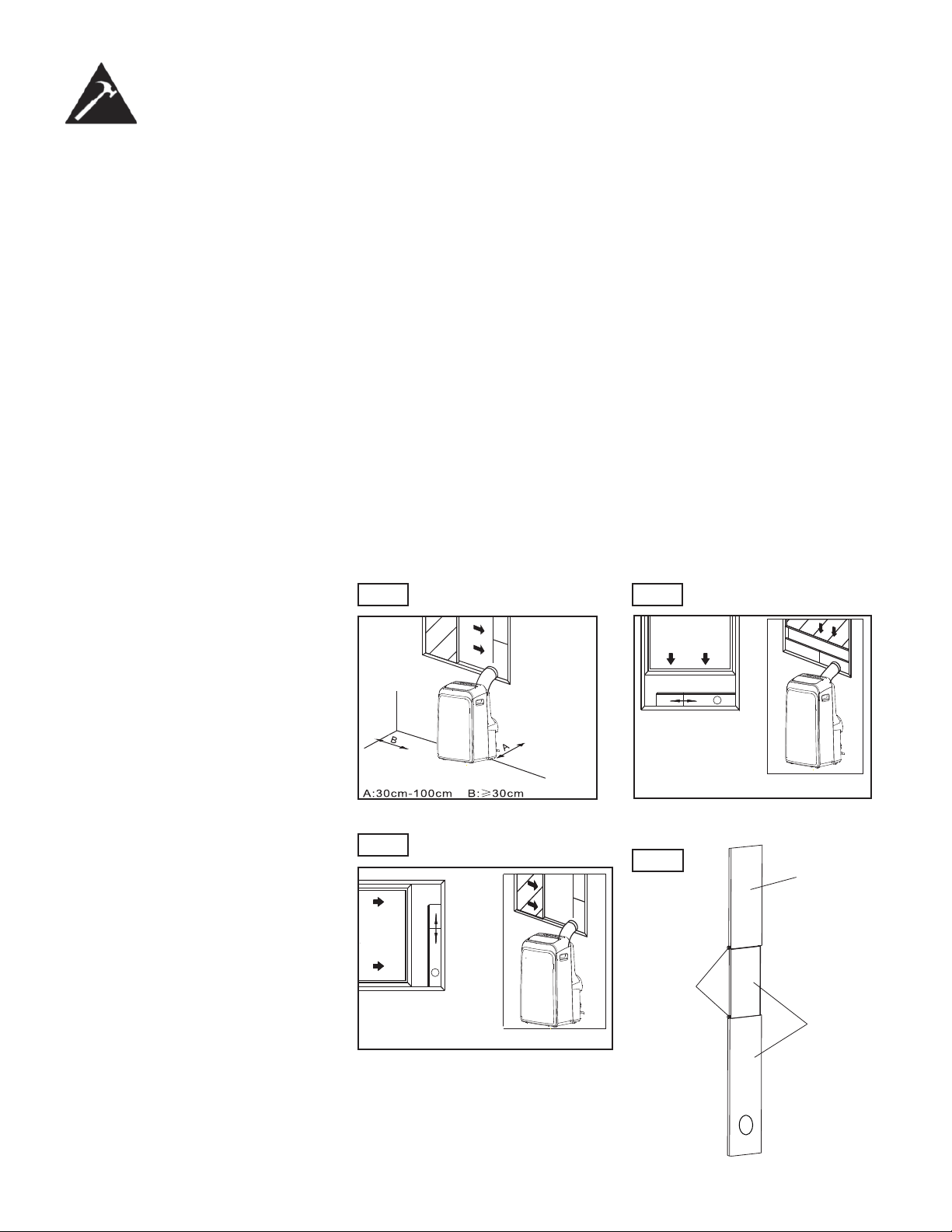
WINDOW SLIDER KIT
INSTALLATION
Your window slider kit has been designed to fi t most standard vertical and hori-
zontal window applications, however, it may be necessary for you to modify some
aspects of the installation procedures for certain types of windows. Please refer to
Fig. 6 and Fig. 7 for minimum and maximum window openings. The window slider
kit can be fastened with a screw (see Fig. 8)
NOTE: If the window opening is less than the mentioned minimum length of the
window slider kit, cut the end without the hole in it short enough to fi t in the window
opening. Never cut out the hole in window slider kit (visit www.danby.com for
general instruction videos).
9
Fig.5 Fig.6
Fig.7
Vertical
Window
Window Slider Kit
Minimum:72.0cm(2.36ft).
Maxmum:207.0cm(6.79ft).
Horizontal
Window
Window Slider Kit
Minimum:72.0cm(2.36ft).
Maxmum:207.0cm(6.79ft).
Fig.8
Screw
Window
slider
kit
Patio kit
Pins
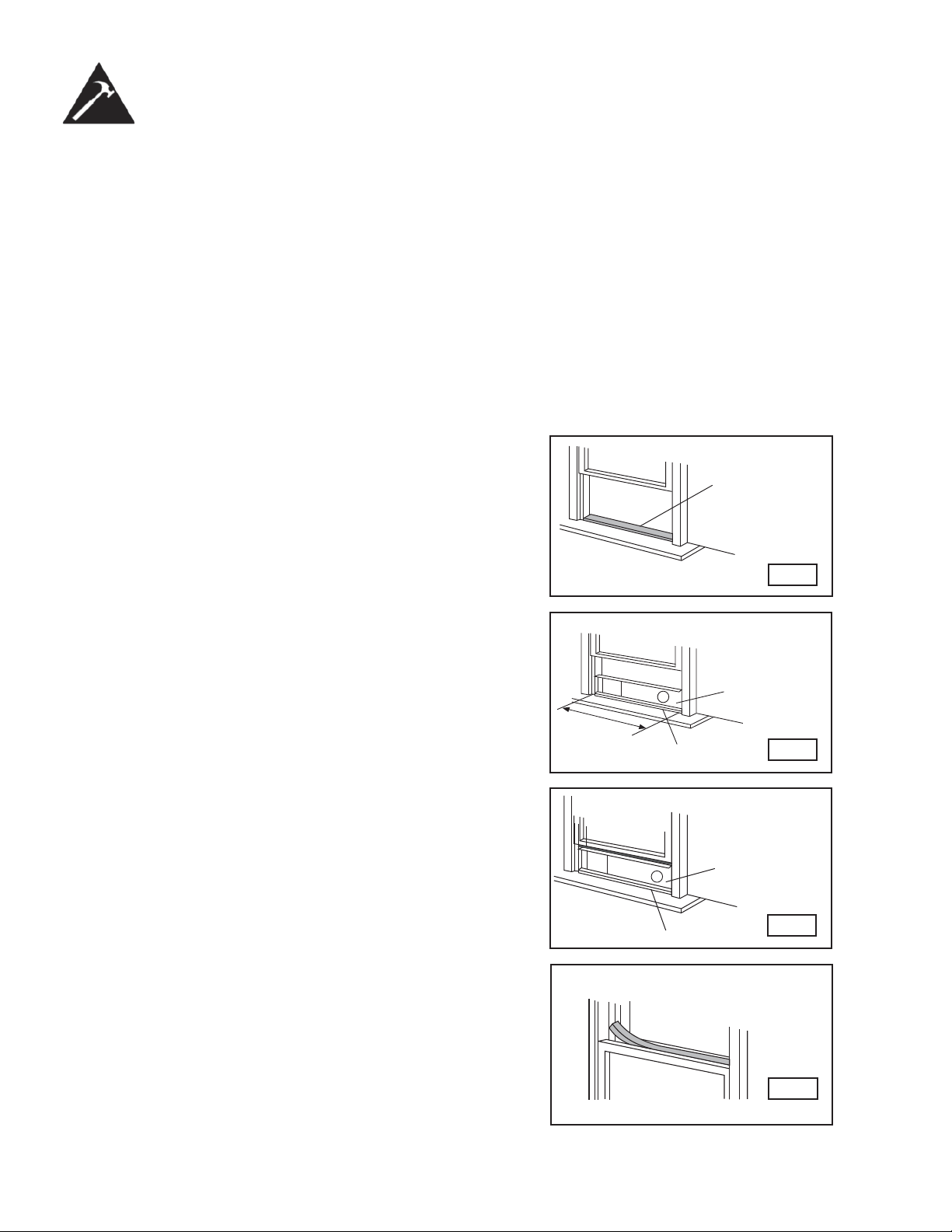
Installation Instructions
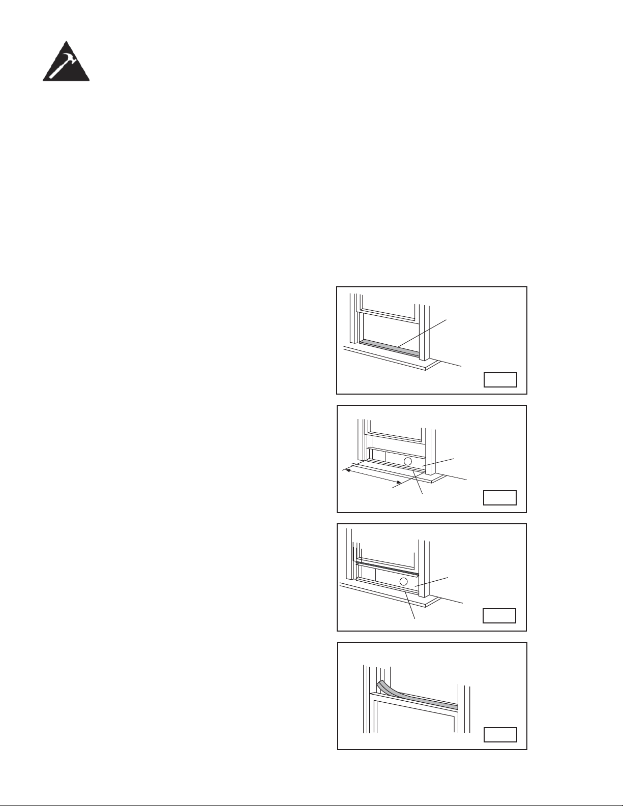
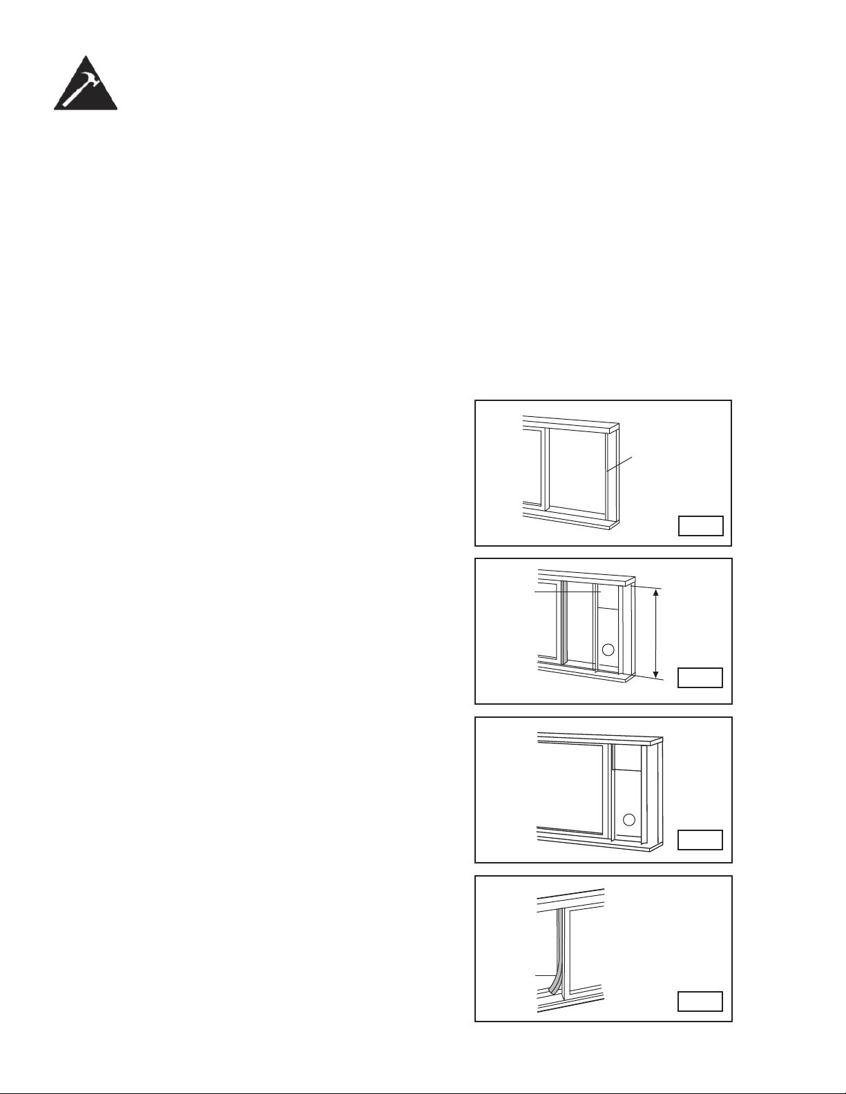
INSTALLATION IN A
DOUBLE-HUNG SASH
WINDOW
1. Measure the adhesive foam seal to fi t the window stool. Then cut the foam seal
to the proper length and attach it to the window stool. Fig.9
2. Adjust the length of the window slider kit to fi t the width of the window.
Shorten the adjustable window kit to fi t the width of the window if less than 72 cm
(28.3 inches). Open the window sash and place the window slider kit on the window
stool. Fig.10
3. Cut the foam seal (adhesive type) to the proper length and attach it on the top of
the window. Shown in Fig.11
4. Close the window sash securely against the window.
5. Cut the foam seal to an appropriate length and seal the open gap between the
top window sash and outer window sash. Shown in Fig.12.
Foam seal A
(adhesive type)
Fig.9
Fig.12
Foam seal
Fig.10
Window Stool
Fig.11
Window Kit
Window Stool
Window Kit
28.3 in.
~
81.5 in.
72 cm - 2.7 m
10
Installation Instructions
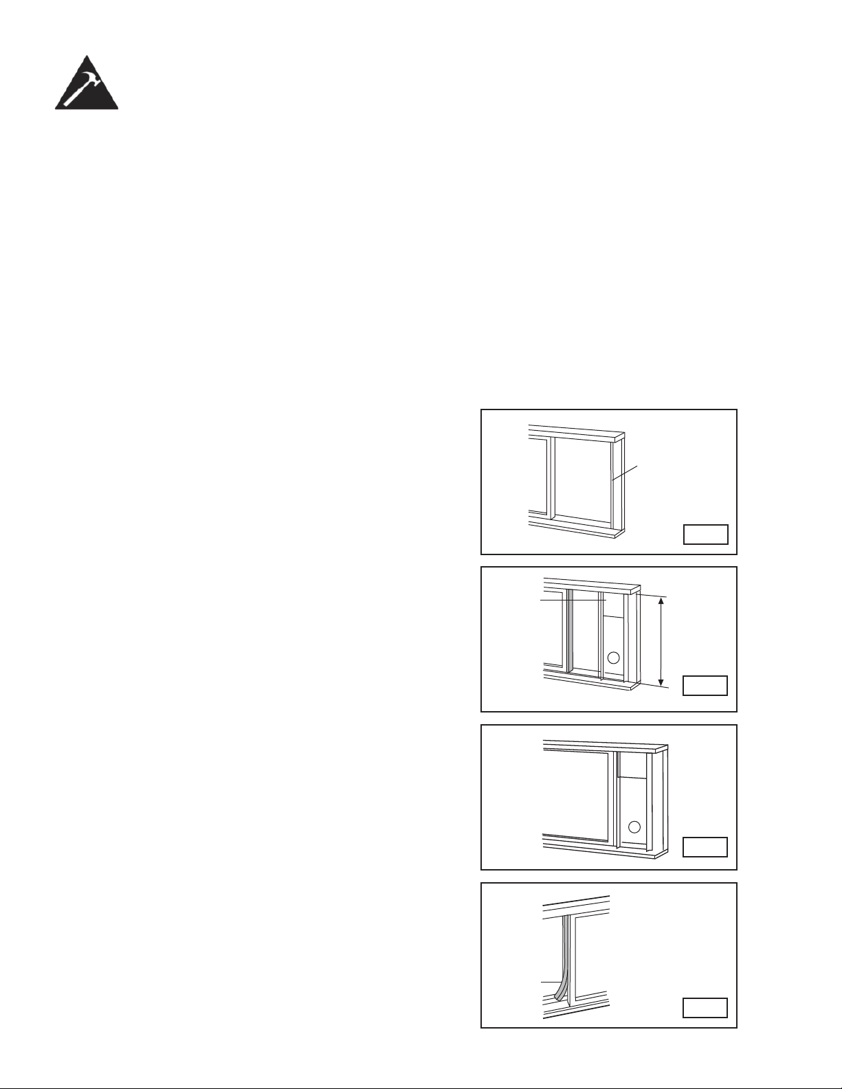
INSTALLATION IN A
SLIDING SASH
WINDOW
1. Measure the adhesive foam seal to fi t the window stool. Cut the foam seal (ad-
hesive type) to the proper length and attach it to the window frame. See fi g. 13.
2. Adjust the length of the window slider kit according to the height of the window,
shorten the adjustable window kit if the height of the window slider is less than
72 cm (28.3 inches). Open the window sash and place the window slider kit on
the window stool. See fi g. 14.
3. Cut the foam seal (adhesive type) to the proper length and attach it to the top
of the window. Shown in fi g. 15.
4. Close the sliding sash securely against the window.
5. Cut the foam seal to an appropriate length and seal the open gap between the
top window sash and outer window sash. Shown in fi g. 16.
Foam seal A
(adhesive type)
Fig.13
Fig.14
Window
Panel
Fig.15
Foam
Seal
Fig.16
28.3 in. ~ 81.5 in.
72 cm ~ 2,7 m]
11
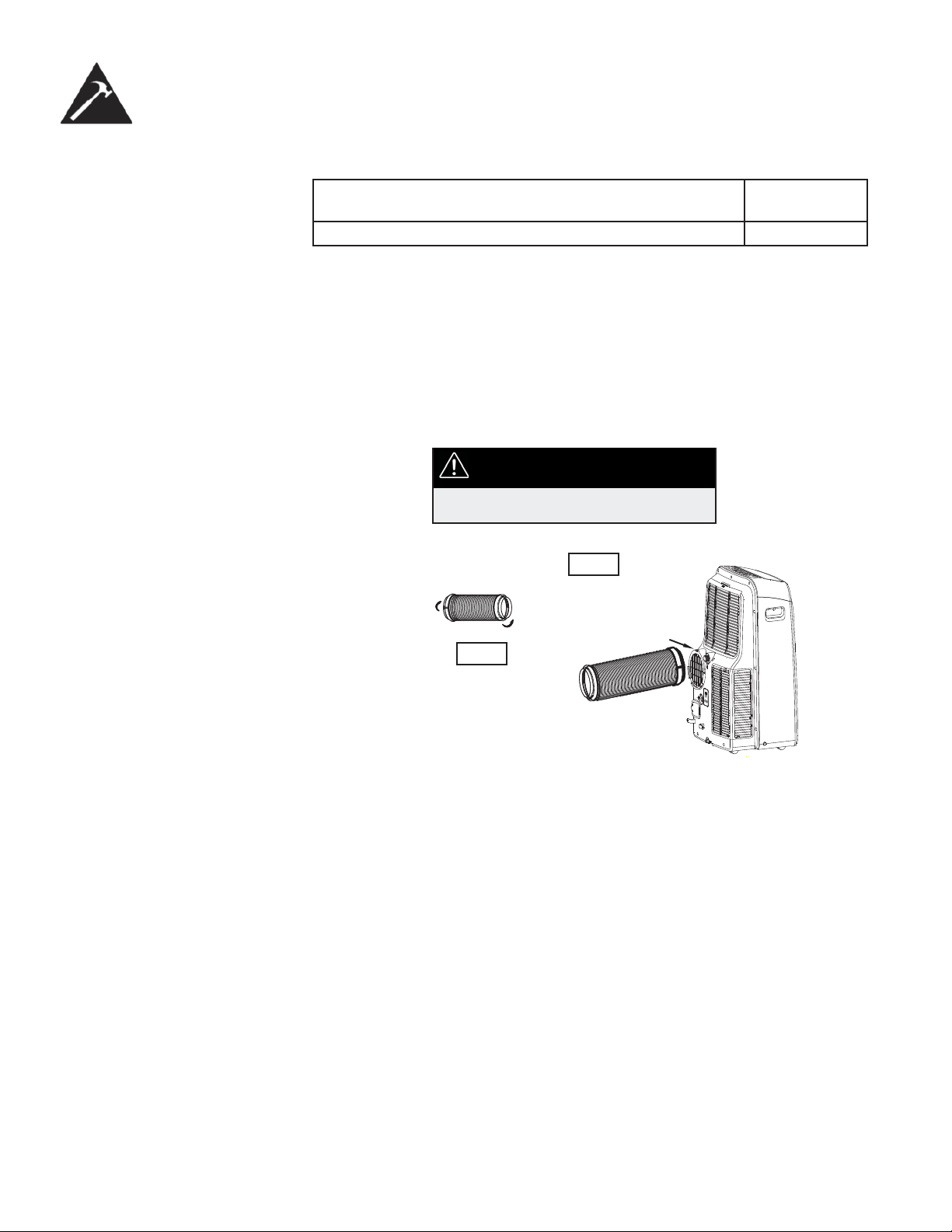
Installation Instructions
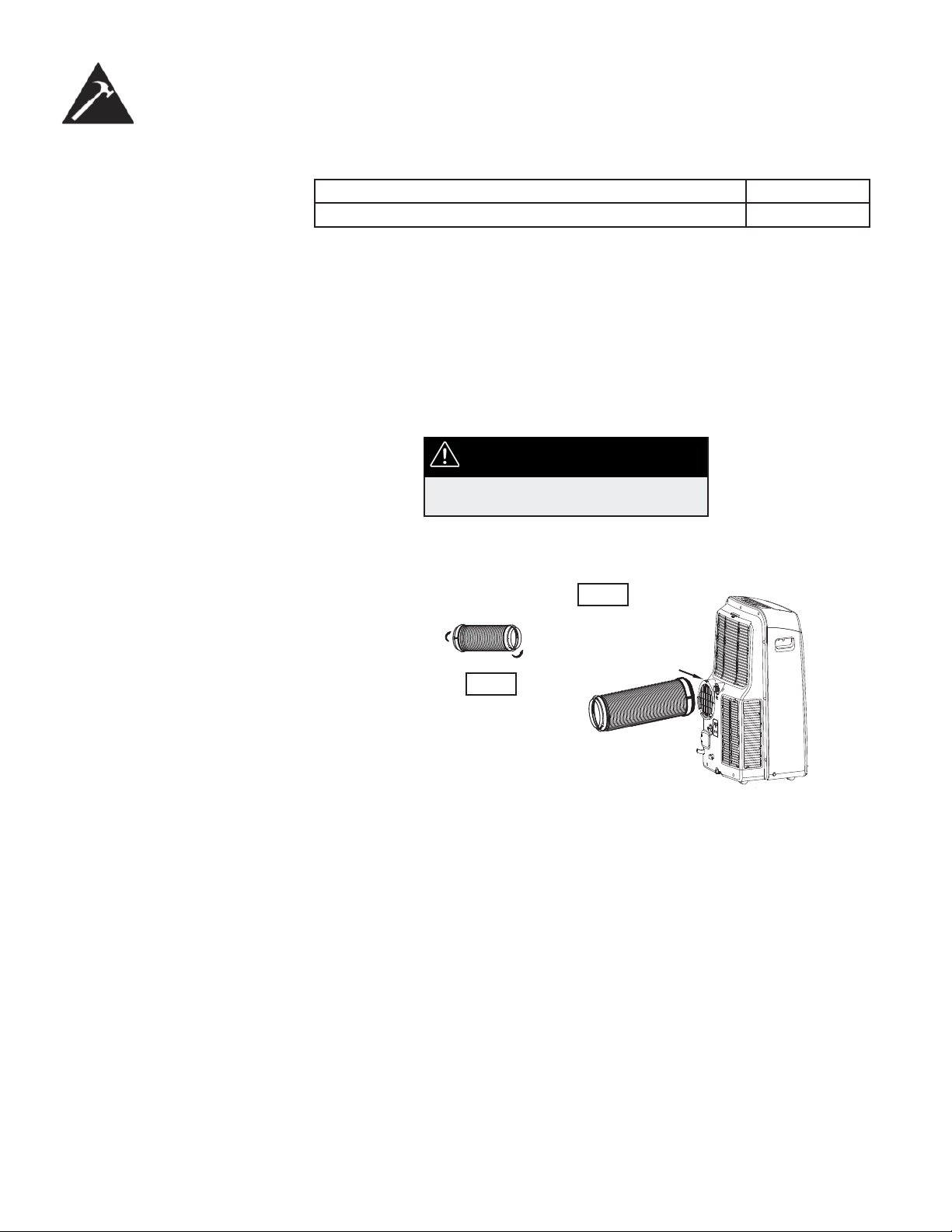
EXHAUST HOSE
INSTALLATION
The exhaust hose and adaptor must be installed or removed in accordance with the
usage mode.
1. Install the window exhaust adaptor onto the exhaust hose as shown in Fig. 18.
Refer to the previous pages for window kit installation.
2. Insert the exhaust hose into the rear air outlet opening along the arrow direction
(see fi g. 19).
• The hose can be compressed or extended moderately according to the installation
requirement, but it is desirable to keep the hose length to a minimum.
IMPORTANT
DO NOT OVER-BEND THE HOSE
COOL, HEAT (heat pump type) or AUTO mode Install
FAN or DEHUMIDIFY mode Remove
Fig.19
Fig.18
12
Remove the
upper drain
plug
Continuous
drain hose
Fig.22a
Fig.22b
Fig.24
Continuous
drain hose
Remove the
lower drain
plug
Fig.23a Fig.23b
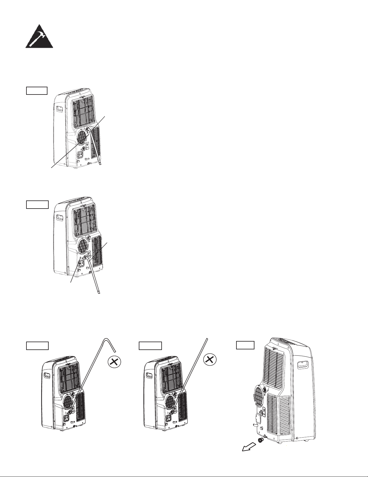
Installation Instructions
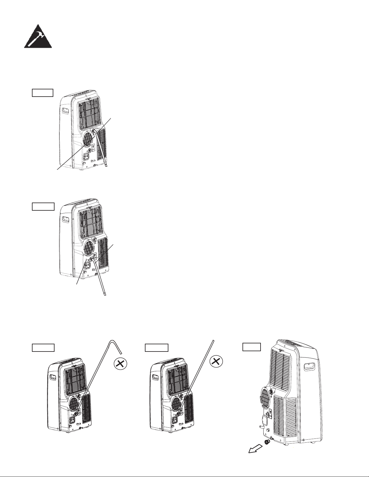
WATER DRAINAGE
• During dehumidifying modes, remove the upper drain plug from the back of
the unit, install the drain connector (5/8 in. universal female connecter) with
3/4 in. hose (not included). For the models without a drain connector, just
attach the drain hose to the hole. Place the open end of the hose directly over
the drain area in your basement fl oor. Please refer to Fig. 22.
NOTE: Make sure the hose is secure so there are no leaks. Direct the hose
toward the drain, making sure that there are no kinks that will stop the water
from fl owing. Place the end of the hose into the drain and make sure the end
of the hose is down to let the water fl ow smoothly. (see Fig. 22). Never raise
it. (See Fig 23a, 23b).
• When the water level of the bottom tray reaches a predetermined level,
the unit beeps 8 times, the digital display area shows P1. At this time the air
conditioning/dehumidifi cation process will immediately stop. However, the
fan motor will continue to operate (this is normal). Carefully move the unit to
a drain location, remove the bottom drain plug and let the water drain away
(Fig. 24). Restart the machine until the P1 symbol disappears. If the error
repeats, call for service.
NOTE: When operating or draining water, always protect carpeting or fl oors
from possible water spillage.
NOTE: Be sure to reinstall the bottom drain plug before using the unit.
13
Care and Maintenance
IMPORTANT
1. Be sure to unplug the unit before cleaning or servicing.
2. Do not use gasoline, paint thinner or other chemicals to clean the
unit.
3. Do not wash the unit directly under a tap or using a hose. It may
cause electrical damage.
4. If the power cord is damaged, contact the service depot immediately.
AIR FILTER
UNIT ENCLOSURE
Use a lint-free cloth soaked with neutral detergent to clean the unit enclosure,
be sure to wring the cloth of excess water. Finish by wiping with a clean dry
cloth.
LONG-TERM STORAGE
• Remove the rubber plug at the back of the unit and attach a hose to the drain
outlet. Place the open end of the hose directly over the drain area in your base-
ment fl oor.
• Remove the plug from the bottom drain outlet, this means that all the water in
the bottom drain tray will drain out.
• Keep the appliance running on FAN mode for half a day in a warm room to dry
the appliance inside and prevent mold formation.
• Turn off the appliance and unplug it, wrap the cord and bundle it with tape.
• Remove the batteries from the remote controller.
• Clean the air fi lter and reinstall it.
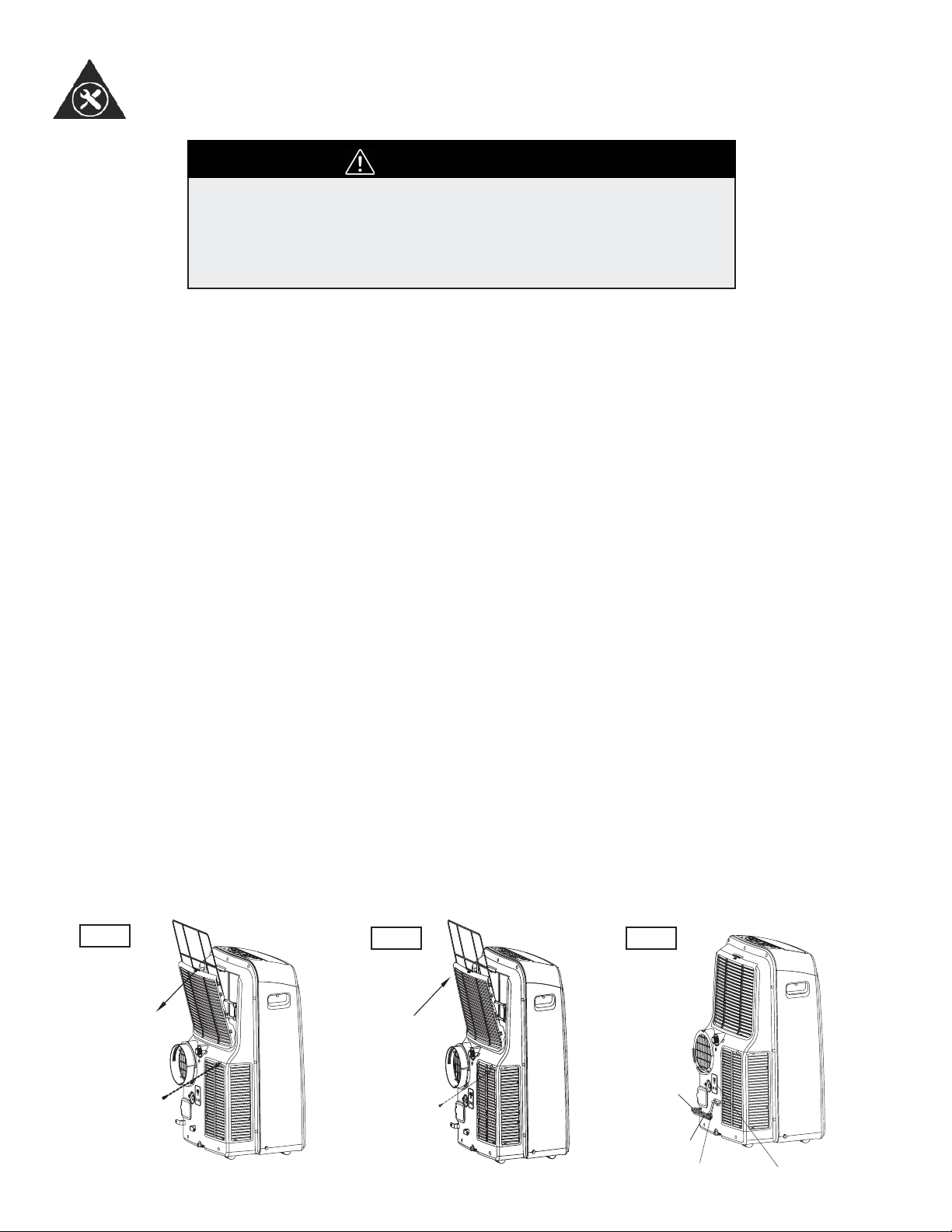
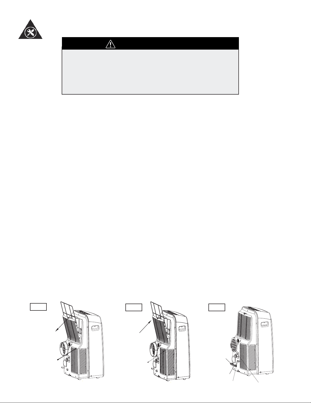
Clean the air fi lter at least once every two weeks. Accumulation of dust will hinder fan
operation.
REMOVAL
This unit has two fi lters. Lift the upper fl iter out in the direction of the arrow (Fig. 25),
then down. Remove the lower fi lter by loosening the screw and lifi ng out the fi lter as
shown in Fig. 25.
CLEANING
1. Wash the air fi lter by submerging it gently in warm water (about 40°C / 104° F)
with a neutral detergent.
2. Rinse the fi lter and let it dry.
REINSTALL
Install the upper air fi lter after cleaning, and install the lower fi lter after, using the screw
(see Fig. 26). *Filters should dry before installing*
Fig.25
Fig.26 Fig.27
Upper filter
(Take out)
Remove the
screw ,then
take the lower
filter out.
Upper filter
(Install)
Install the
lower filter
by using
the screw.
Buckle
Power
cord
Power plug
Power plug socket
14
15
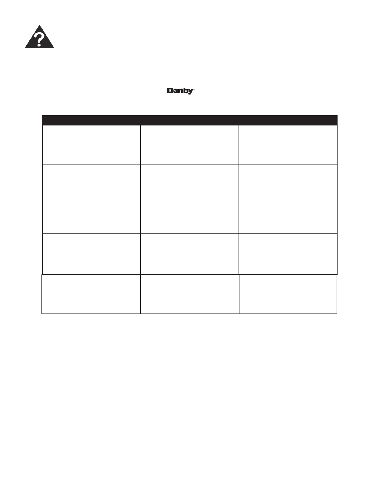
Troubleshooting
Occasionally, a minor problem may arise, and a service call may not be necessary- use this troubleshooting guide for
a possible solution. If the unit continues to operate improperly, call an authorized service depot or Danby’s Toll Free
Number for assistance.
Tel: 1-800-26- (1-800-263-2629)
PROBLEM POSSIBLE CAUSE SOLUTION
Unit does not start when press-
ing on/off button
• P1 appears in the display
window
• Room temperature is lower
than the set temperature.
(Cooling mode)
• Drain the water in the bottom
tray
• Reset the temperature
Not cool enough • The windows or doors in the
room are not closed
• There are heat sources inside
the room
• Exhaust air hose is not con-
nected or blocked
• Temperature setting is too
high
• Air fi lter is blocked by dust
• Make sure all the windows
and doors are closed
• Remove the heat sources if
possible
• Connect the hose and make
sure it can function properly
• Decrease the set temperature
• Clean the air fi lter
Noisy or vibration • The ground is not level or not
fl at enough
• Place the unit on a fl at, level
ground if possible
Gurgling sound • The sound comes from the
fl owing of the refrigerant
inside the air conditioner
• It is normal
DISPOSAL
Check for local regulatory compliance regarding the approved and safe disposal of this appliance.
Power shut-off at heating mode • This is the automatic over
heat protection function.
When the temperature at
the air outlet exceeds 70°C /
158°F, the device will stop
• Switch on again after the unit
has cooled down. Reduce
temperature settings.
LIMITED IN-HOME APPLIANCE WARRANTY
This quality product is warranted to be free from manufacturer’s defects in material and workmanship, provided that the unit is used under the normal operating
conditions intended by the manufacturer.
This warranty is available only to the person to whom the unit was originally sold by Danby Products Limited (Canada) or Danby Products Inc. (U.S.A.) (hereafter
“Danby”) or by an authorized distributor of Danby, and is non-transferable.
TERMS OF WARRANTY
Plastic parts, are warranted for thirty (30) days only from purchase date, with no extensions provided.
First Year
During the rst twelve (12) months, any functional parts of this product found to be defective, will be repaired or replaced, at warrantor’s
option, at no charge to the ORIGINAL purchaser.
To obtain
Danby reserves the right to limit the boundaries of “In Home Service” to the proximity of an Authorized Service Depot. Any app liance
Service
requiring service outside the limited boundaries of “In Home Service” , it will be the consumer’s responsibility to transport the appliance (at
their own expense) to the original retailer (point of purchase) or a service depot for repair. See “Boundaries of In Home Serv ice” below.
Contact your dealer from whom your unit was purchased, or contact your nearest authorized Danby service depot, where service
must be performed by a qualied service technician.
If service is performed on the units by anyone other than an authorized service depot, or the unit is used for commercial appli cation, all
obligations of Danby under this warranty shall be void.
Boundaries of
If the appliance is installed in a location that is 100 kilometers (62 miles) or more from the nearest service center your unit must be
In Home Service
delivered to the nearest authorized Danby Service Depot, as service must only be performed by a technician qualied and certif ied for
warranty service by Danby. Transportation charges to and from the service location are not protected by this warranty and are t he
responsibility of the purchaser.
Nothing within this warranty shall imply that Danby will be responsible or liable for any spoilage or damage to food or other c ontents of this appliance, whether due
to any defect of the appliance, or its use, whether proper or improper.
EXCLUSIONS
Save as herein provided, Danby, there are no other warranties, conditions, representations or guarantees, express or implied, m ade or intended by Danby or its
authorized distributors and all other warranties, conditions, representations or guarantees, including any warranties, conditio ns, representations or guarantees
under any Sale of Goods Act or like legislation or statue is hereby expressly excluded. Save as herein provided, Danby shall no t be responsible for any damages
to persons or property, including the unit itself, howsoever caused or any consequential damages arising from the malfunction o f the unit and by the purchase of
the unit, the purchaser does hereby agree to indemnify and hold harmless Danby from any claim for damages to persons or propert y caused by the unit.
GENERAL PROVISIONS
No warranty or insurance herein contained or set out shall apply when damage or repair is caused by any of the following:
1) Power failure.
2) Damage in transit or when moving the appliance.
3) Improper power supply such as low voltage, defective house wiring or inadequate fuses.
4) Accident, alteration, abuse or misuse of the appliance such as inadequate air circulation in the room or abnormal operating con ditions
(extremely high or low room temperature).
5) Use for commercial or industrial purposes (ie. If the appliance is not installed in a domestic residence).
6) Fire, water damage, theft, war, riot, hostility, acts of God such as hurricanes, oods etc.
7) Service calls resulting in customer education.
8) Improper Installation (ie. Building-in of a free standing appliance or using an appliance outdoors that is not approved for out door application).
Proof of purchase date will be required for warranty claims; so, please retain bills of sale. In the event warranty service is required, present this document to our
AUTHORIZED SERVICE DEPOT.
Danby Products Limited
PO Box 1778, Guelph, Ontario, Canada N1H 6Z9
Telephone: (519) 837-0920 FAX: (519) 837-0449
Danby Products Inc.
PO Box 669, Findlay, Ohio, U.S.A. 45840
Telephone: (419) 425-8627 FAX: (419) 425-8629
04/09
1-800-263-2629
Warranty Service
In-home
If the appliance is installed in a location that is 100 kilometres (62 miles) or more from the nearest
service centre your unit must be delivered to the nearest authorized Danby Service Depot, as service
must only be performed by a technician qualified and certified for warranty service by Danby. Transpor-
tation charges to and from the service location are not protected by this warranty and are the responsi-
bility of the purchaser.
During the first twelve (12) months, any functional parts of this product found to be defective, will be
repaired or replaced, at warrantor’s option, at no charge to the ORIGINAL purchaser.
Danby reserves the right to limit the boundaries of “In Home Service” to the proximity of an Authorized
Service Depot. Any appliance requiring service outside the limited boundaries of “In Home Service” ,it
will be the consumer’s responsibility to transport the appliance (at their own expense) to the original
retailer (point of purchase) or a service depot for repair. See “Boundaries of In Home Service” below.
Contact your dealer from whom your unit was purchased, or contact your nearest authorized Danby
service depot, where service must be performed by a qualified service technician. If service is performed
on the units by anyone other than an authorized service depot, or the unit is used for commercial
application, all obligations of Danby under this warranty shall be void.
First year
To obtain
service
Boundaries of
in-home service
LIMITED IN-HOME APPLIANCE WARRANTY
This quality product is warranted to be free from manufacturer’s defects in material and workmanship, provided that the unit is
used under the normal operating conditions intended by the manufacturer.
This warranty is available only to the person to whom the unit was originally sold by Danby Products Limited (Canada) or
Danby Products Inc. (U.S.A.) (hereafter “Danby”) or by an authorized distributor of Danby, and is non-transferable.
TERMS OF WARRANTY
Plastic parts, are warranted for thirty (30) days only from purchase date, with no extensions provided.
Nothing within this warranty shall imply that Danby will be responsible or liable for any spoilage or damage to food or other
contents of this appliance, whether due to any defect of the appliance, or its use, whether proper or improper.
EXCLUSIONS
Save as herein provided, by Danby, there are no other warranties, conditions, representations or guarantees, express or
implied, made or intended by Danby or its authorized distributors and all other warranties, conditions, representations or
guarantees, including any warranties, conditions, representations or guarantees under any Sale of Goods Act or like legislation
or statute is hereby expressly excluded. Save as herein provided, Danby shall not be responsible for any damages to persons
or property, including the unit itself, howsoever caused or any consequential damages arising from the malfunction of the unit
and by the purchase of the unit, the purchaser does hereby agree to indemnify and hold harmless Danby from any claim for
damages to persons or property caused by the unit.
GENERAL PROVISIONS
No warranty or insurance herein contained or set out shall apply when damage or repair is caused by any of the following:
1) Power failure.
2) Damage in transit or when moving the appliance.
3) Improper power supply such as low voltage, defective house wiring or inadequate fuses.
4) Accident, alteration, abuse or misuse of the appliance such as inadequate air circulation in the room or abnormal operating
conditions (extremely high or low room temperature).
5) Use for commercial or industrial purposes (i.e., If the appliance is not installed in a domestic residence).
6) Fire, water damage, theft, war, riot, hostility, acts of God such as hurricanes, floods etc.
7) Service calls resulting in customer education.
8) Improper Installation (i.e., building-in of a free standing appliance or using an appliance outdoors that is not approved for
outdoor application). Proof of purchase date will be required for warranty claims; so, please retain bills of sale. In the event
warranty service is required, present this document to our AUTHORIZED SERVICE DEPOT.
Warranty Service
In-home
Danby Products Limited
PO Box 1778, Guelph, Ontario, Canada N1H 6Z9
Telephone: (519) 837-0920 FAX: (519) 837-0449
Danby Products Inc.
PO Box 669, Findlay, Ohio, U.S.A. 45840
Telephone: (419) 425-8627 FAX: (419) 425-8629
1-800-263-2629
07/14
Bienvenue
Bienvenue dans la famille Danby. Nous sommes fiers de la qualité de nos produits et nous croyons fermement au serv-
ice par une assistance fiable. Vous le découvrirez à la lecture de ce guide facile d’utilisation et vous en aurez la confir-
mation par notre service d’assistance à la clientèle. Mais ce qui est encore mieux, vous pourrez bénéficier de ces avan-
tages à chaque utilisation de votre appareil. Ceci est important parce que votre nouvel appareil fera partie de votre
famille pour longtemps.
Veuillez noter les informations ci-dessous; ces renseignements seront nécessaires si votre appareil a besoin
d’entretien ou pour les demandes de renseignements généraux. Pour bénéficier d’une opération de mainte-
nance ou de dépannage, le reçu original sera exigé.
Numéro de modèle :
Numéro de serie :
Date d’achat :
BESOIN D’ASSISTANCE ?
Veuillez trouver quelques conseils avant de faire appel à nos
services, cela nous aidera à mieux vous servir :
Lisez ce guide :
Il comprend des instructions pour l’utilisation et l’entretien
adapté de votre appareil.
Si votre nouvel appareil est endommagé :
Contactez immédiatement le revendeur (ou le fabricant).
Gagnez du temps et de l’argent :
Avant de faire appel à nos services, consultez à nouveau
la section « Dépannage ». Cette section vous aidera à
résoudre des problèmes courants.
Si une réparation est nécessaire, ne vous inquiétez pas, la
solution est au bout du fil.
1-800-26-
(1-800-263-2629)
10
17

18
Consignes de sécurité importantes
LISEZ TOUTE L’INFORMATION DE SÉCURITÉ AVANT UTILISATION
Pour votre sécurité : Lisez ces instructions attentivement avant d’utiliser l’appareil et conservez-les
afi n de pouvoir vous y référer ultérieurement.
PRÉCAUTIONS
DE SÉCURITÉ
SUIVEZ TOUJOURS CES CONSIGNES
L’appareil doit être utilisé dans un endroit à l’abri de l’humidité, comme la
condensation, les éclaboussures d’eau, etc. Ne le placez pas dans un
endroit où il pourrait tomber dans l’eau ou d’autres liquides.
Transportez toujours l’appareil en position verticale. Utilisez-le sur une sur-
face stable et de niveau. Si l’appareil est transporté, couché, il faudra le
remettre en position verticale et le garder débranché pendant 4 heures.
Éteignez le produit s’il n’est pas utilisé.
Faites faire toute réparation par un technicien qualifi é. Si le cordon
d’alimentation est endommagé, il doit être réparé par un technicien qualifi é.
Laissez un espace libre d’au moins 30 cm (1 pied) autour de l’appareil
(p.ex., des murs, des meubles et des rideaux) pour permettre un bonne
circulation de l’air.
Si le climatiseur tombe alors qu’il est en marche, éteindre l’appareil et le
débrancher immédiatement.
Utilisez toujours l’interrupteur du panneau de commande pour éteindre
l’appareil ou le mettre en marche.
Les climatiseurs mobiles détournent de grandes quantités d’air de la salle.
Toujours assurer un approvisionnement suffi sant d’air afi n de fonctionner
effi cacement.
MISES EN GARDE
Ne faites pas fonctionner le climatiseur dans une pièce humide, comme une
salle de bain ou de lavage
Ne touchez pas à l’appareil les mains mouillées ou humides
N’appuyez sur les boutons du panneau de commande qu’avec les doigts
Ne retirez pas les couvercles fi xes. N’utilisez jamais cet appareil s’il
fonctionne mal ou s’il a été échappé ou endommagé
Ne couvrez pas les grilles d’entrée ou de sortie, et ne les obstruez pas
Ne nettoyez pas cet appareil à l’aide de proudits, chimiques dangereux. Ne
les mettez pas en contact avec l’appareil
N’utilisez pas cet appareil en présence de substances infl ammables comme
l’alcool, les insecticides, le gaz, l’essence, etc.
Ne laissez pas les enfants utiliser cet appareil sans surveillance
N’utilisez pas ce proudit pour des fonctions autres que celles décrites dans
ce guide.
Consignes de sécurité importantes
LISEZ TOUTE L’INFORMATION DE SÉCURITÉ AVANT UTILISATION
Pour votre sécurité: Lisez ces instructions attentivement avant d’utiliser l’appareil et conservez-les
afi n de pouvoir vous y référer ultérieurement.
ÉCONOMISEZ
L’ÉNERGIE
CONDITIONS DE
FONCTIONNEMENT
OUTILS POUR L’INSTAL-
LATION DE LA TROUSSE
POUR FENÊTRE
• Utilisez l’appareil dans des pièces des dimensions recommandées.
• Placez l’appareil dans un endroit où les meubles n’obstruent pas la
circulation d’air.
• Fermez les stores et rideaux pendant les moments les plus ensoleillés
de la journée.
• Gardez le fi ltre de l’appareil propre.
• Fermez les portes et les fenêtres pour garder l’air froid à l’intérieur et
l’air chaud à l’extérieur.
Le climatiseur doit être utilisé à l’intérieur de la plage de température
qui fi gure ci-dessous :
Remarque : Une température hors de ces plages peut réduire le rende-
ment.
1. Tournevis (moyen, à lame plate)
2. Ruban à mesure ou règle
3. Couteau ou ciseaux
4. Scie (si la trousse pour fenêtre doit être coupée parce que la fenêtre
est trop étroite pour une installation directe.)
Voir www.danby.com pour obtenir un guide d’instrucions pour
l’installation générale.
Identifi cation des pièces
AVERTISSEMENT
• Ne conservez et n’utilisez ni essence, ni vapeurs ou substances liquides infl ammables à proximité de cet
appareil ou de tout autre appareil.
• Évitez les risques de feu ou de choc électrique. N’utilisez pas de rallonge ou d’adaptateur. N’enlevez pas
de broche sur le cordon d’alimentation.
RENSEIGNEMENTS RELATIFS À L’ÉLECTRICITÉ
AVERTISSEMENT
• Assurez-vous que l’alimentation en électricité correspond au modèle que vous avez choisi. Ces
informations sont disponibles sur la plaque signalétque, qui se trouve sur côté du châssis et derrière la
grille.
• Assurez-vous que le climatiseur est correctement mis à la terre. Une mis à la terre correcte est
importante pour minimiser les risques de choc et de feu. Le cordon d’alimentation est muni d’une prise
de mise à la terre à trois broches pour vous protéger contre les risques de choc.
• Votre climatiseur doit être branché sur une prise murale correctement mise à la terre. Si la prise murale
que vous prévoyez utiliser n’est pas mise à la terre correctement ou protégée par un fusible à fusion
lente ou un disjoncteur, demandez à un électricien qualifi é d’installer la bonne prise.
• Assurez-vous que la prise sera accessible après l’installation de l’appareil.
19
MODE TEMPÉRATURE DE LA PIÈCE
REFROIDISSEMENT 17°C (62°F) ~ 35°C (95°F)
DÉSHUMIDIFICATION 13°C (55°F) ~ 35°C (95°F)
CHAUFFAGE (modèle pomp thermique) 5°C (41°F) ~ 30°C (86°F)
CHAUFFAGE (électrique ou pomp ther-
mique)
<30°C / 86°F
20
Identifi cation des pièces
ACCESSOIRES
PIÈCES NOM DES PIÈCES QUANTITÉ
Tuyau d’évacuation et adapteur;
trousse de glissière de fenêtre
et épingles
1 ensemble
Joint d’étanchéité en mousse 6 pièces
Télécommande et piles (pour
les modèles télécommandés
seulement)
1 ensemble
Tuyau de vidange et raccord de
tuyau de vidange*
1 pièce
• Assurez-vous que tous les accessoires sont inclus dans l’emballage et consultez la notice d’installation
pour connaître leur utilisation.
REMARQUE : Toutes les illustrations contenues dans ce manuel servent à des fi ns d’explication seulement.
Votre climatiseur peut être légèrement différent. La forme réelle aura préséance.
STRUCTURE DE L’APPAREIL
1
2
3
4
AVANT
Panneau de commande
Lame du louvre horizontal
(pivote automatiquement)
Roulette
Poignée de transport
(sur les deux côtés)
Fig.1
P
M
ET
O
T
U
A
L
OO
C
R
D
Y
E
H
T
A
F
N
A
H
G
I
H
D
E
M
O
L
W
EDOM
F
DE
E
P
S
N
A
G
N
IWS
N
O
REMI
T
Y
MO
NOCE
FF
O/
N
O
F
FORE
M
I
T
RE
SE
T
L
OC
K
W
O
L
L
O
F
E
M
D
E
L
Y
A
L
P
S
I
D
N
O
I
O
B
RUT
L’identifi cation des pièces
Caractéristiques
INSTRUCTIONS RELATIVES AUX COMMANDES
ÉLECTRONIQUES
Avant de commencer, familiarisez-vous avec le panneau de commande et la télécommande et toutes leurs fonctions, puis
suivez le symbole correspondant à la fonction désirée.
L’appareil peut être commandé par le panneau de commande seulement ou par la télécommande.
Remarque : Ce manuel ne comprend pas les fonctions de la télécommande, voir les « Instructions relatives à la
télécommande »
21
ARRIÈRE
Filtre à air supérieur (derrière la grille)
Supérieur entrée d’air
Sortie d’air
Sortie de drain (seulement pour les
modèles à pompe thermique)
Sortie du cordon d'alimentation
Boucle du cordon d'alimentation (utilisé
uniquement lorsque vous rangez l'appareil)
Sortie du drain du plateau du bas
Prise de courant (utilisé uniquement
lorsque vous rangez l'appareil)
Filtre à air inférieur (derrière la grille)
Inférieur entrée d’air
Sortie de drainage
Fig.2
6
7
8
9
10
11
12
13
5
14
15
Fig.3
1
2
34
4
567
8

Caractéristiques
INSTRUCTIONS RELATIVES
AUX COMMANDES
ÉLECTRONIQUES
22
Bouton POWER (MARCHE/ARRÊT)
Allume/éteint l’appareil.
Bouton SLEEP (SOMMEIL)
Utilisé pour accéder au programme SOMMEIL.
Bouton FAN (VENTILATEUR)
Contrôle la vitesse du ventilateur. Appuyez sur ce bouton pour sélectionner
la vitesse du ventilateur dans l’ordre suivant : BASSE (appuyes 1 fois),
MOYENNE (appuyez 2 fois) et ÉLEVÉE (appuyez 3 fois). L’indicateur de la
vitesse du ventilateur correspondant à la vitesse sélectionnée.
Appuyez sur ce bouton une quatrième fois pour initier le mode
AUTO-VENTILATEUR. Dans ce mode, tous les trois indicateurs de la vitesse
du ventilateur s’allument.
Boutons PLUS et MOINS
Utilisés pour régler (augmenter/diminuer) les réglages de température
(intervalles de 1°C/1°F) sur une plage de 17°C/62°F à 30°C (86°F), ou les
réglages du minuteur sur une plage de 0 à 24 heures. La commange peut
affi cher la température en degrés Fahrenheit out en degrés Celsius. Pour
passer d’une échelle à l’autre, appuyez sur les boutons Plus et Moins au
même moment et maintenez-les enfoncés pendant 3 secondes.
Bouton de sélection du MODE
Permet de sélectionner le mode de fonctionnement approprié. Chaque fois
que vous appuyez sur le bouton, un mode est sélectionné dans l’ordre
suivant : AUTO, COOL, (REFROIDISSEMENT), DRY (DÉSHUMIDIFICATION et
FAN (VENTILATEUR). L’indicateur de mode correspondant au mode sélectionné
s’allume.
Bouton TIMER (MINUTEUR)
Utilisé pour amorcer le programme de mise en marche automa-
tique et de fi n automatique, conjointement avec les fl èches
ascendante et descendate.
Bouton d’OSCILLATION (SWING)
(Disponible sur certaines modèles.) Appuyez sur ce bouton pour initier
l’option de l’oscillation automatique des défl ecteurs. Lorsque l’oscillation
automatique est sélectionnée, appuyez sur ce bouton encore une fois, pour
arrêter les défl ecteurs à l’angle désiré.
Affi cage à DEL
Indique la température réglée en °C ou °F et affi che les réglages de minuteur
automatique. En modes DÉSHUMIDIFICATION ou VENTILATEUR, il indique
la température de la pièce.
Codes d’erreur :
E1 - Erreur du capteur de température de la pièce : débranchez
et rebranchez l’appareil. Si l’erreur se reproduit, appelez l’atelier de
réparation.
E2 - Erreur du capteur de température de l’évaporateur : débranchez
et rebranchez l’appareil. Si l’erreur se reproduit, appelez l’atelier de
réparation.
E3 - Erreur du condensateur de - Débranchez l’appareil et rebran-
chez-le. Si l’erreur se répète, veuillez communiquer avec le service.
E4 - Erreur de communication de l’affi cheur : débranchez et rebran-
chez l’appareil. Si l’erreur se reproduit, appelez l’atelier de réparation.
P1 - Le plateau inférieur est plein : raccordez le tuyau de drainage et
videz l’eau accumulée. Si l’erreur se reproduit, appelez l’atelier de
réparation.
1
2
3
4
5
6
7
8

Consignes d’utilisation
MODE D’EMPLOI
23
Fonction REFROIDISSEMENT
-Appuyez sur le bouton « MODE » jusqu’à ce que l’indicateur lumineux « COOL »
s’allume.
-Appuyez sur les boutons fl èche ascendante ou descendante pour sélectionner la
température de la pièce que vous désirez. La température peut être réglée entre
17°C et 30°C (62°F à 86°F).
-Appuyez sur le bouton « FAN SPEED » pour sélectionner la vitesse du ventilateur.
Fonction AUTOMATIQUE
-Lorsque vous réglez le climatiseur en mode AUTO, il sélectionne automatiquement
le fonctionnement de refroidissement, ou de ventilateur seulement, en fonction de
la température sélectionnée et de la température de la pièce.
-Le climatiseur contrôle automatiquement la température de la pièce afi n qu’elle
soit maintenue automatiquement à la température sélectionnée.
-En mode AUTO, vous ne pouvez pas sélectionner la vitesse du ventilateur.
Fonction VENTILATEUR
-Appuyez sur le bouton « MODE » jusqu’à ce que l’indicateur lumineux « FAN »
s’allume.
-Appuyez sur le bouton « FAN SPEED » pour sélectionner la vitesse du ventila-
teur. (Appuyez 1 fois pour la vitesse BASSE, 2 fois pour la MOYENNE, 3 fois pour
l’ÉLEVÉE et 4 fois pour sélectionner AUTO-VENTILATEUR).
-L’indicateur lumineux correspondant à la vitesse sélectionnée s’allume. Tous les
trois indicateurs lumineux s’allument lorsque l’option AUTO-VENTILATEUR est
sélectionnée.
-Le température ne peut pas être réglée.
-Ne faites pas passer la conduite par la fenêtre dans ce mode.
Fonction MINUTEUR
-Lorsque l’appareil est en marche, appuyez d’abord sur le bouton TIMER; l’indica-
teur lumineux TIMER OFF (ARRÊT MINUTEUR) s’allume. Il indique que le pro-
gramme d’arrêt automatique est amorcé.
-Lorsque l’appareil est éteint, appuyez d’abord sur le bouton TIMER; l’indicateur
lumineux TIMER ON (DÉPART MINUTEUR) s’allume. Il indique que le programme
de mise en marche automatique est amorcé.
-Appuyez sur les boutons PLUS ou MOINS ou maintenez-les enfoncés pour
modifi er l’heure automatique par intervalles de o,5 heure jusqu’à 10 heures, puis
par intervalles de 1 heure jusqu’à 24 heures. La commande effectue un compte à
rebours jusqu’à l’heure du début.
-L’heure sélectionnée apparaît en 5 secondes et le système retourne automatique-
ment à l’affi chage du réglage de température précédent.
-Le fait d’allumer ou d’éteindre l’appareil ou de régler le réglage du minuteur à 0,0
annule les fonctions d’arrêt/de mise en marche automatique.
-En cas d’anomalie (E1, E2, E3, E4 ou P1), le programme d’arrêt / de mise en
marche automatique sera également annulé.
Fonction CHAUFFAGE
- Appuyez sur le bouton « MODE » jusqu’à ce que l’indicateur lumineux « HEAT »
s’allume.
-Appuyez sur la ascendante ou la descendante boutons pour sélectionner la
température de la pièce que vous désirez. La température peut être réglée entre
17°C et 30°C (62°F à 86°F).
-Appuyez sur le bouton « FAN SPEED » pour sélectionner la vitesse du ventila-
teur. Pour certains modèles, la vitesse du ventilateur ne peut pas être sélection-
née en mode CHAUFFAGE.
24
Consignes d’utilisation
MODE D’EMPLOI
PANNE DE COURANT
RÉGLAGE DE LA DI-
RECTION DU COURANT
D’AIR
En cas de panne ou d’interruption du courant, l’appareil se remet automatiquement
en marche, selon les derniers réglages utilisés, après le rétablissement du courant.
Attendez 3 minutes avant de reprendre le fonctionnement.
Après l’arrêt de l’appareil, il ne peut pas être remis en marche dans les 3 minutes
qui suivent le rétablissement du courant. Cette caractéristique sert à protéger l’ap-
pareil. Le fonctionnement reprendra automatiquement au bout de 3 minutes.
Fonction SOMMEIL
Si vous appuyez sur ce bouton, la température sélectionnée augmentera (en mode
refroidissement) de 1°C / 2°F en 30 minutes. La température sélectionnée augmen-
tera (en mode refroidissement) encore de 1°C / 2°F au bout de 30 minutes supplé-
mentaires. Cette nouvelle température sera conservée pendant 7 heures, avant de
revenir à la valeur initiale. Cela met fi n au mode sommeil et l’appareil continuera de
fonctionner conformément à sa programmation initale.
Ajustez la direction du courant d’air automatiquement (Fig. 4) :
-Les défl ecteurs peuvent être ajustés automatiquement pour changer la direction
du courant d’air.
-Lorsque l’appareil est en marche, les défl ecteurs sont complètement ouverts.
-appuyez sur le bouton SWING (OSCILLANT) du panneau ou de la télécommande
pour activer la fonction d’Auto swing (oscillant automatique).
-Le défl ecteur oscillera de haut en bas automatiquement.
Ne pas régler le défl ecteur manuellement.
Oscille automatiquement
Fig. 4
25
Consignes d’installation
EMPLACEMENT
• Le climatiseur doit être placé sur une fondation solide pour minimiser le bruit et les
vibrations. Pour la sûreté, placez l’appareil sur un plancher lisse et de niveau, assez
fort pour le supporter.
• L’appareil est doté de roulettes pour faciliter son déplacement. Il ne doit être roulé que
sur des surfaces lisses et planes. Soyez prudent lorsque vous roulez sur des tapis. Ne
roulez pas l’appareil par-dessus des objets. Soyez prudent et protégez les planchers
en bois si vous faites rouler l’appareil dessus.
• L’appareil doit être utilisé à distance d’une prise homologuée et mise à la terre, ne
dépassant pas la longueur du cordon d’alimentation.
• Ne placez jamais d’obstacles autour de l’entrée ou de la sortie d’air de l’appareil.
• Laissez au moins 30 cm (1 pi) d’espace libre entre le mur et l’appareil afi n de per-
mettre une climatistion effi ciente.
INSTALLATION DE LA
TROUSSE DE
GLISSIÈRE POUR
FENÊTRE
Votre trousse de glissière pour fenêtre est conçue pour s’adapter à la plupart des
fenêtres à ouverture horizontale ou verticale. Toutefois, vous devrez peut-être impro-
viser ou modifi er certains aspects des procédures d’installation pour certains types de
fenêtres. Veuillez consulter la Fig. 6 et la Fig. 7 pour obtenir les ouvertures maximales
et minimales des fenêtres. La trousse de glissière pour fenêtre peut être fi xée au moy-
en d’une vis (Fig. 8)
REMARQUE : Si l’ouverture de la fenêtre est inférieure à la longueur minimale in-
diquée pour la trousse de glissière pour fenêtre, coupez celle qui contient un trou pour
qu’elle entre dans l’ouverture de la fenêtre. Ne coupez jamais la section de la trousse
de glissière pour fenêtre où se trouve le trou. (Voir www.danby.com pour obtenir
une vidéo d’instructions générales.)
Fig.5 Fig.6
Fig.7
Fenêtre
verticale
Trousse de glissière pour fenêtre
fenêtre
horizontale
Trousse de glissière pour fenêtre
Minimum : 72,0 cm (2,36 pi).
Maximum : 207,0 cm (6,79 pi).
Minimum : 72,0 cm (2,36 pi).
Maximum : 207,0 cm (6,79 pi).
Fig.8
Vis
Trousse
de
glissière
de
fenêtre
necessaires
pour porte
patio
épingles
26
Consignes d’installation
INSTALLATION DANS
UNE FENÊTRE À
GUILLOTINE DOUBLE
1. Mesurer le joint adhésif en mousse à la longueur du rebord de la fenêtre.
Coupez le joint d’étanchéité en mousse (adhésif) à la longueur appropriée et
fi xez-le au rebord de la fenêtre. Fig. 9.
2. Fixez la trousse de glissière pour fenêtre au rebord de la fenêtre. Ajustez la
longueur de la trousse de glissière pour fenêtre en fonction de la largeur de la
fenêtre; raccourcissez la trousse réglable pour fenêtre si la largeur de la fenêtre
est inférieure à 72 cm (28.3 pouces). Ouvrez le châssis de fenêtre et posez la
trousse de glissière pour fenêtre sur le rebord de la fenêtre. Fig. 10.
3. Coupez le joint d’étanchéité en mousse (adhésif) à la longueur appropriée et
fi xez-le au dessus de la fenêtre. Tel qu’illustré dans la fi g. 11.
4. Fermez bien le châssis de fenêtre.
5. Coupez le joint d’étanchéité en mousse à la longueur appropriée et scellez l’es-
pace ouvert entre le châssis supérieur et le châssis extérieur de la fenêtre. Tel
qu’illustré dans la fi g. 12.
Joint d’étanchéité
en mousse A
(adhésif)
Fig.9
Fig.12
Joint d’étanchéité
en mousse
Fig.10
Rebord de fenêtre
Fig.11
Trousse pour fenêtre
Rebord de fenêtre
Trousse pour
fenêtre
28.3 in. ~ 81.5 in.
71 cm à 2,7 m
27
Consignes d’installation
INSTALLATION DANS
UNE FENÊTRE
COULISSANTE
1. Coupez le joint d’étanchéité en mousse (adhésif) à la longueur appropriée et
fi xez-le au cardre de la fenêtre. Voir fi g. 13.
2. Fixez la trousse de glissière pour fenêtre au rebord de la fenêtre. Ajustez la
longueur de la trousse de glissière pour fenêtre en fonction de la hauteur de la
fenêtre est inférieure à 72 cm (28.3 pouces). Ouvrez le châssis de fenêtre et
posez la trousse de glissière pour fenêtre sur le rebord de la fenêtre. Voir fi g. 14.
3. Coupez le joint d’étanchéité en mousse (adhésif) à la longueur appropriée et
fi xez-le au dessus de la fenêtre, tel qu’illustré à la fi g. 15
4. Fermez bien la fenêtre coulissante.
5. Coupez le joint d’étanchéité en mousse à la longueur appropriée et scellez
l’espace ouvert entre le châssis supérieur et le châssis extérieur de la fenêtre, tel
qu’illustré à la fi g. 16.
Joint d’étanché-
ité en mousse A
(adhésif)
Fig.13
Fig.14
Panneau
de la
fenêtre
Fig.15
Joint
d’étanch-
éité en
mousse
Fig.16
28.3 in. ~ 81.5 in.
72 cm ~ 2,7 m
28
Consignes d’installation
INSTALLATION DU
TUYAU D’ÉVACUATION
Le tuyau d’évacuation et l’adaptateur doivent être installés ou enlevés, selon le
mode d’utilisation.
1. Installez l’adaptateur d’évacuation pour fenêtre dans le tuyau d’évacuation, tel
qu’illustré dans la fi g. 18. Reportez-vous aux pages précédentes pour l’installa-
tion de la trousse pour fenêtre.
2. Insérez le tuyau d’évacuation dans l’ouverture de sortie de l’air, dans la direc-
tion de la fl èche (voir fi g. 19).
• La conduite peut être légèrement comprimée ou étirée selon les besoins de l’in-
stallation, mais il est préférable d’en réduire la longueur au minimum.
AVERTISSEMENT
NE PAS TROP PLIER LA CONDUITE
Modes REFROIDISSEMENT, CHAUFFAGE (thermo-
pompe) ou AUTO
Installer
Mode VENTILATEUR, ou DÉSHUMIDIFICATION Enlever
Fig.19
Fig.18
Enlevez le
bouchon du drain
du haut
Tuyau de drainage
continu
Fig.22a
Fig.22b
Fig.24
Tuyau de drainage
continu
Enlevez le bouchon
du drain du bas
Fig.23a Fig.23b
29
Consignes d’installation
DRAINAGE DE L’EAU
•En mode déshumidifi cation, enlevez le supérieur bouchon de
drainage de l’arrière de l’appareil et installez le raccord de drain
(raccord femelle universel 5/8 po) sur un tuyau de 3/4 po (non
compris). Pour les modèles sans raccord de drain, fi xez directe-
ment le tuyau à l’orifi ce. Placez l’extrémité ouverte du tuyau
directement au-dessus de drain qui se trouve dans le plancher
de votre sous-sol. Veuillez-vous référer à la fi g. 22.
REMARQUE : S’assurer que le tuyau soit bien fi xé pour éviter
toute fuite. Diriger le tuyau bers le drain, s’assurer que le tuyau
ne soit pas entortillé pour freiner le débit de l’eau. Mettre le
tuyau dans le drain et s’assurer que le bout soit droit et dirigé
vers le bas pour laisser couler l’eau. (Voir fi g. 22). Ne jamais le
lever (Voir fi g. 23a, 23b)
•Lorsque le niveau du plateau inférieur atteint une valeur prédé-
terminée, l’appareil émet 8 bips et l’affi cheur indique « P1 ». Le
processus de refroidissement ou de déshumidifi cation s’arrête
automatiquement. Toutefois, le moteur du ventilateur continue
de fonctionner (c’est normal). Déplacez soigneusement l’appar-
eil jusqu’à un lieu de drainage, enlevez le couchon de drainage
inférieur et laissez l’eau se vider (fi g. 24). Remettez l’appareil
en marche, jusqu’à ce que le symbole P1 disparaisse. Si l’er-
reur se reproduit, appelez l’atelier de réparation.
REMARQUE : Lors du fonctionnement ou du drainage de l’eau,
protégez toujours les tapis et les planchers des renversements
d’eau possibles.
REMARQUE : Avant d’utiliser l’appareil, assurez-vous de re-
poser le bouchon du drain du bas.
30
Soins et entretien
AVERTISSEMENT
1. Veillez à débrancher l’appareil avant de le nettoyer ou de procéder à
son entretien.
2. N’utilisez pas d’essence, de diluant ou d’autres produits chimiques
pour nettoyer l’appareil.
3. Ne lavez pas l’appareil directment sous le robinet ou à l’aide d’un
tuyau : vous pourriez vous électrocuter ou causer un incendie.
4. Si le cordon d’alimentation est endommagé, il doit être réparé par le
fabricant ou l’un de ses représentants de l’entretien.
FILTRE À AIR
Comme le fi ltre accumule et expluse de la poussière, il doit être nettoyé toutes les deux
semaines pour assurer le fonctionnement de qualité supérieure du ventilateur.
RETRAIT DU FILTRE À AIR
Cet appareil dispose de deux fi ltres. Sortir le fi ltre du haut dans la direction de la fl èche
comme indiqué sur la fi g. 25. Enlevez le fi ltre du bas en dévissant la vis et le sortir com-
me indiqué sur la fi g. 25.
NETTOYAGE DU FILTRE À AIR
1. Nettoyez le fi ltre à air en l’immergeant dans l’eau tiède (environ 40°C/104°F)
conenant un détergent doux.
2. Rincez le fi ltre et séchez-le dans un endroit ombragé.
REMPLACEMENT
Après le nettoyage, installez le fi ltre à air du haut et ensuite celui du bas en utilisant la vis
(voir la fi g. 26). Avant d’installer, les fi ltres doivent être secs.
ENCEINTE DE
L’APPAREIL
Pour nettoyer l’enceinte de l’appareil, servez-vous d’un chiffon non
pelucheux trempé dans un détergent neutre, assurez-vous d’aspirer le tissu de
l’excès d’eau . Finissez le nettoyage en essuyant l’appareil avec un chiffon propre
et sec.
ENTREPOSAGE À
LONG TERME
• Enlevez le bouchon en caoutchouc qui se trouve à l’arrière de l’appareil, puis raccor-
dez un tuyau à l’orfi ce de drainage. Placez l’extrémité ouverte du tuyau directement
au-dessus du drain qui se trouve dans le plancher de votre sous-sol.
• Enlevez le bouchon de l’orifi ce de sortie inférieur : toute l’eau contenue dans le pla-
teau inférieur se videra.
• Faites fonctionner l’appareil en mode VENTILATEUR pendant un demi-journée dans
une pièce chaude pour sécher l’intérieur de l’appareil et empêcher la formation de
moisissure.
• Arrêtez l’appareil et débranchez-le, enroulez le cordon et attachez-le au moyen du
ruban adhésif. (fi g. 27)
• Retirez les piles de la télécommande.
• Nettoyez le fi ltre à air et remettez-le en place.
Fig.25
Fig.26 Fig.27
Filtre
supérieur
(retrait)
Ôtez la vis et
enlevez-le filtre
du bas
Filtre supérieur
(installation)
Posez le filtre
du bas en
utilisant la vis
Boucle
Cordon
d’alimentation
Prise de courant
Prise de courant

31
Dépannage
De temps en temps, un problème est mineur et un appel de service peut ne pas être nécessaire. Utilisez ce guide de
dépannage pour trouver une solution possible. Si l’unité continue de fonctionner incorrectement, appelez un dépôt de
service autorisé ou le numéro sans frais de Danby pour obtenir de l’assistance.
Tel: 1-800-26- (1-800-263-2629)
PROBLÈME CAUSE POSSIBLE SOLUTION
L’appareil ne se met pas en
marche après une pression sur
le bouton Marche/Arrêt
• P1 apparaît dans l’affi cheur
• La température de la pièce
est inférieure à la tempéra-
ture réglée (mode refroidisse-
ment)
• Drainez l’eau du plateau
inférieur
• Réglez la température à
nouveau
Pas assez frais • Les portes ou les fenêtres de
la pièce ne sont pas fermées
• Il y a des sources de
chauffage dans la pièce
• La conduite d’évacution n’est
pas raccordée ou est bloquée
• La température est réglée à
une température trop élevée
• Le fi ltre à air est bloqué par la
poussière
• Assurez-vous que toutes les
portes et les fenêtres sont
fermées
• Si possible, enlevez les
sources de chaleur
• Raccordez la conduite et as-
surez-vous qu’elle fonctionne
correctement
• Diminuez la température
réglée
• Nettoyez le fi ltre à air
Bruits ou vibrations • Le sol n’est pas horizontal ou
assez plat
• Si possible, posez l’appar-
eil sur une surface plate et
horizontale
Gargouillis • Ce son provient du mouve-
ment du fl uide frigorigène
dans le climatiseur
• C’est normal
MISE AU REBUT
Vérifi ez le respect des réglementations locales concernant la mise au rebut approuvée et sécurisée de cet
appareil.
Coupure de l’alimentation en
mode chauffage
• La fonction de protection
automatique contre la sur-
chauffe. Lorsque la températ-
ue à la sortie d’air dépasse
70°C/158°F, l’appareil arrête
de fonctionner
• Remettez-le en marche après
qu’il aura refroidi
LIMITED IN-HOME APPLIANCE WARRANTY
This quality product is warranted to be free from manufacturer’s defects in material and workmanship, provided that the unit is used under the normal operating
conditions intended by the manufacturer.
This warranty is available only to the person to whom the unit was originally sold by Danby Products Limited (Canada) or Danby Products Inc. (U.S.A.) (hereafter
“Danby”) or by an authorized distributor of Danby, and is non-transferable.
TERMS OF WARRANTY
Plastic parts, are warranted for thirty (30) days only from purchase date, with no extensions provided.
First Year
During the rst twelve (12) months, any functional parts of this product found to be defective, will be repaired or replaced, at warrantor’s
option, at no charge to the ORIGINAL purchaser.
To obtain
Danby reserves the right to limit the boundaries of “In Home Service” to the proximity of an Authorized Service Depot. Any app liance
Service
requiring service outside the limited boundaries of “In Home Service” , it will be the consumer’s responsibility to transport the appliance (at
their own expense) to the original retailer (point of purchase) or a service depot for repair. See “Boundaries of In Home Serv ice” below.
Contact your dealer from whom your unit was purchased, or contact your nearest authorized Danby service depot, where service
must be performed by a qualied service technician.
If service is performed on the units by anyone other than an authorized service depot, or the unit is used for commercial appli cation, all
obligations of Danby under this warranty shall be void.
Boundaries of
If the appliance is installed in a location that is 100 kilometers (62 miles) or more from the nearest service center your unit must be
In Home Service
delivered to the nearest authorized Danby Service Depot, as service must only be performed by a technician qualied and certif ied for
warranty service by Danby. Transportation charges to and from the service location are not protected by this warranty and are t he
responsibility of the purchaser.
Nothing within this warranty shall imply that Danby will be responsible or liable for any spoilage or damage to food or other c ontents of this appliance, whether due
to any defect of the appliance, or its use, whether proper or improper.
EXCLUSIONS
Save as herein provided, Danby, there are no other warranties, conditions, representations or guarantees, express or implied, m ade or intended by Danby or its
authorized distributors and all other warranties, conditions, representations or guarantees, including any warranties, conditio ns, representations or guarantees
under any Sale of Goods Act or like legislation or statue is hereby expressly excluded. Save as herein provided, Danby shall no t be responsible for any damages
to persons or property, including the unit itself, howsoever caused or any consequential damages arising from the malfunction o f the unit and by the purchase of
the unit, the purchaser does hereby agree to indemnify and hold harmless Danby from any claim for damages to persons or propert y caused by the unit.
GENERAL PROVISIONS
No warranty or insurance herein contained or set out shall apply when damage or repair is caused by any of the following:
1) Power failure.
2) Damage in transit or when moving the appliance.
3) Improper power supply such as low voltage, defective house wiring or inadequate fuses.
4) Accident, alteration, abuse or misuse of the appliance such as inadequate air circulation in the room or abnormal operating con ditions
(extremely high or low room temperature).
5) Use for commercial or industrial purposes (ie. If the appliance is not installed in a domestic residence).
6) Fire, water damage, theft, war, riot, hostility, acts of God such as hurricanes, oods etc.
7) Service calls resulting in customer education.
8) Improper Installation (ie. Building-in of a free standing appliance or using an appliance outdoors that is not approved for out door application).
Proof of purchase date will be required for warranty claims; so, please retain bills of sale. In the event warranty service is required, present this document to our
AUTHORIZED SERVICE DEPOT.
Danby Products Limited
PO Box 1778, Guelph, Ontario, Canada N1H 6Z9
Telephone: (519) 837-0920 FAX: (519) 837-0449
Danby Products Inc.
PO Box 669, Findlay, Ohio, U.S.A. 45840
Telephone: (419) 425-8627 FAX: (419) 425-8629
04/09
1-800-263-2629
Warranty Service
In-home
Si l'appareil est installé à plus de 100 kilomètres (62 milles) du centre de service le plus proche, il doit
être livré à l'atelier de réparation autorisé par Danby le plus proche, car l'entretien doit uniquement être
réalisé par un technicien qualifié et certifié pour effectuer un entretien couvert par la garantie de Danby.
Les frais de transport entre votre domicile et le lieu de l'entretien ne sont pas couverts par la présente
garantie et doivent être acquittés par l'acheteur.
Pendant les premiers douze (12) mois, toutes les pièces fonctionnelles de ce produit qui s’avèrent
défectueuses seront réparées ou remplacées, selon le choix du garant, sans frais à l’acheteur INITIAL.
Le client sera responsable pour le transport et tous les frais d’expédition de tout appareil exigeant le
service au dépot de service autorisé le plus proche. S’adresser au détaillant qui a vendu l’appareil, ou à
la station technique agréée de service la plus proche, où les réparations doivent être effectuées par un
technicien qualifié. Si les réparations sont effectuées par quiconque autre que la station de service
agréée où à des fins commerciales, toutes les obligations de Danby en vertu de cette garantie seront
annulées.
Premiers 12 mois
Pour bénéficier
du service
Limites de
l’entretien à
domicile
GARANTIE LIMITÉE SUR
APPAREIL ÉLECTROMÉNAGER À DOMICILE
Cet appareil de qualité est garanti exempt de tout vice de matière première et de fabrication, s’il est utilisé dans les conditions
normales recommandées par le fabricant.
Cette garantie n’est offerte qu’à l’acheteur initial de l’appareil vendu par Danby Products Limited (Canada) ou Danby Products
Inc. (E.- U.A.) (ci-après « Danby ») ou par l’un des ses distributeurs agréés et elle ne peut être transférée.
CONDITIONS
Les pièces en plastique sont garanties pendant trente (30) jours seulement à partir de la date de l’achat, sans aucune prolon-
gation prévue.
Aucune partie de la garantie ne prévoit implicitement que le fabricant sera tenu responsable des dommages subis par les
aliments ou d’autres types de contenu, qu’ils soient causés par la défectuosité de l’appareil ou par son usage adéquat ou
inadéquat.
EXCLUSIONS
En vertu de la présente, il n’existe aucune autre garantie, condition ou représentation, qu’elle soit exprimée ou tacite, de façon
manifeste ou intentionnelle, par Danby ou ses distributeurs agréés. De même, sont exclues toutes les autres garanties,
conditions ou représentations, y compris les garanties, conditions ou représentations en vertu de toute loi régissant la vente
de produits ou de toute autre législation ou règlement semblables. En vertu de la présente, Danby ne peut être tenue respon-
sable en cas de blessures corporelles ou des dégâts matériels, y compris à l’appareil, quelle qu’en soit les causes. Danby ne
peut pas être tenue responsable des dommages indirects dus au fonctionnement défectueux de l’appareil. En achetant
l’appareil, l’acheteur accepte de mettre à couvert et de dégager Danby de toute responsabilité en cas de réclamation pour
toute blessure corporelle ou tout dégât matériel causé par cet appareil.
CONDITIONS GÉNÉRALES
La garantie ou assurance ci-dessus ne s’applique pas si les dégâts ou réparations sont dus aux cas suivants :
1) Panne de courant.
2) Dommage subis pendant le transport ou le déplacement de l’appareil.
3) Alimentation électrique incorrecte (tension faible, câblage défectueux, fusibles incorrects).
4) Accident, modification, emploi abusif ou incorrect de l’appareil tel qu'une circulation d'air inadéquate dans la pièce ou des
conditions de fonctionnement anormales (température extrêmement élevée ou basse).
5) Utilisation dans un but commercial ou industriel (à savoir, si l'appareil n'est pas installé dans un domicile résidentiel).
6) Incendie, dommages causés par l’eau, vol, guerre, émeute, hostilités, cas de force majeure (ouragan, inondation, etc.).
7) Visites d’un technicien pour expliquer le fonctionnement de l’appareil au propriétaire.
8) Installation inappropriée (par exemple, encastrement d'un appareil autoportant, ou utilisation extérieure d'un appareil non
conçu à cet effet). Une preuve d’achat doit être présentée pour toute demande de réparation sous garantie. Prière de garder
le reçu. Pour faire honorer la garantie, présenter ce document à la station technique agréée ou s’adresser à :
Service sous garantie
Service au domicile
Danby Products Limited
PO Box 1778, Guelph, Ontario, Canada N1H 6Z9
Téléphone : (519) 837-0920 Télécopieur: (519) 837-0449
Danby Products Inc.
PO Box 669, Findlay, Ohio, U.S.A. 45840
Téléphone: (419) 425-8627 Télécopieur: (419) 425-8629
1-800-263-2629
03/14

NOTES / REMARQUES :
__________________________________________________________________________________________
__________________________________________________________________________________________
__________________________________________________________________________________________
__________________________________________________________________________________________
__________________________________________________________________________________________
__________________________________________________________________________________________
__________________________________________________________________________________________
__________________________________________________________________________________________
__________________________________________________________________________________________
__________________________________________________________________________________________
__________________________________________________________________________________________
__________________________________________________________________________________________
__________________________________________________________________________________________
__________________________________________________________________________________________
__________________________________________________________________________________________
__________________________________________________________________________________________
__________________________________________________________________________________________
__________________________________________________________________________________________
__________________________________________________________________________________________
__________________________________________________________________________________________
__________________________________________________________________________________________
__________________________________________________________________________________________
All repair parts are available for purchase or special
order when you visit your nearest service depot. To
request service and/or the location of the service depot
nearest you, call the TOLL FREE number.
When requesting service or ordering parts, always pro-
vide the following information:
• Product Type
• Model Number
• Part Number
• Part Description
Toutes les pièces de rechange ou commandes spécia-
les sont disponibles à votre centre de service régional
autorisé. Pour obtenir le service et/ou la localité de
votre centre de service régional, signalez le NUMÉRO
D’APPEL SANS FRAIS.
Ayez les renseignements suivants à la portée de la main
lors de la commande de pièce ou service:
• Type de produit
• Numéro de modèle
• Numéro de pièce
• Description de la pièce
MODEL • MODÈLE
1-800-26-
(1-800-263-2629)
Printed in China
Imprimé en Chine
Danby Products Limited, Guelph, ON, Canada N1H 6Z9
Danby Products Inc., Findlay, Ohio, USA 45840
PORTABLE AIR CONDITIONER CLIMATISEUR PORTATIF
DPA120HCB1WDB / DPA120HUB1WDB