Loading ...
Loading ...
Loading ...
This water heater shall not be connected to any heating
systems or component(s) used with a non-potable water heating
appliance.
Toxic chemicals, such as those used for boiler treatment, shall
not be introduced into this system.
The water supply pressure should not exceed 80 psi. If this
occurs, a pressure reducing valve with a bypass should be
installed in the cold water inlet line. This should be placed on
the supply to the entire house in order to maintain equal hot and
cold water pressures.
In addition, the water within the water heater tank expands as
it is heated, increasing the pressure of the water system. If the
relieving point of the water heater's temperature-pressure relief
valve is reached, the valve will relieve the excess pressure. The
temperature-pressure relief valve is not intended for the
constant relief of thermal expansion. This is an unacceptable
condition and must be corrected. It is recommended that any
devices installed which could create a closed system have a
by-pass and/or the system have an expansion tank to relieve the
pressure built by thermal expansion in the water system. Refer
to the Thermal Expansion section under Troubleshooting Guide
or contact local plumbing authority or local Sears Service Center
on how to control this situation.
NOTE: To protect against untimely corrosion of hot and cold
water fittings, it is strongly recommended that di-electric
unions or couplings be installed on this water heater when
connected to copper pipe.
Property Damage Hazard
• Avoid water heater damage.
• Install thermal expansion tank if necessary.
• Do not apply heat to cold water inlet.
• Contact qualified installer or Sears Service Center.
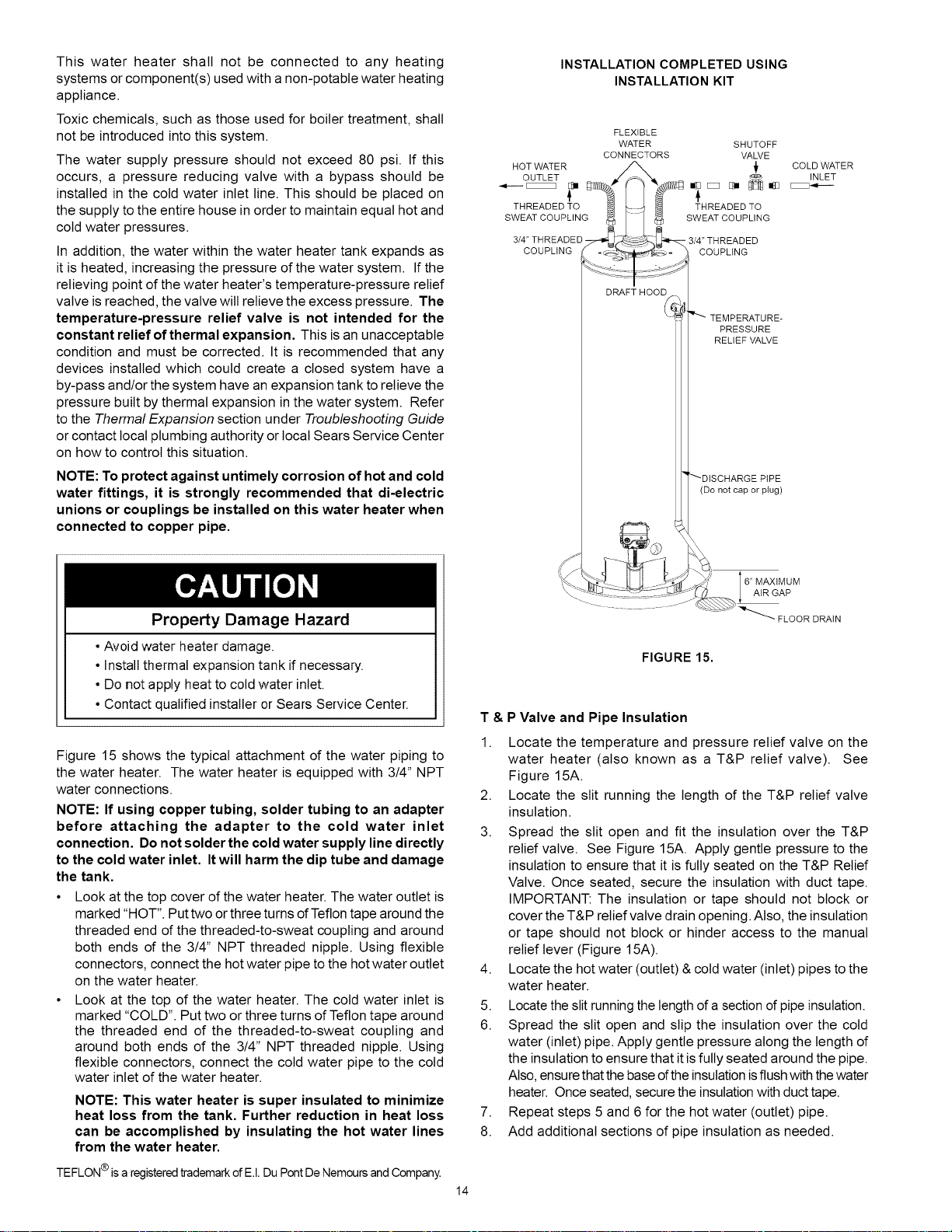
Figure 15 shows the typical attachment of the water piping to
the water heater. The water heater is equipped with 3/4" NPT
water connections.
NOTE: If using copper tubing, solder tubing to an adapter
before attaching the adapter to the cold water inlet
connection. Do not solder the cold water supply line directly
to the cold water inlet. It will harm the dip tube and damage
the tank.
• Look at the top cover of the water heater. The water outlet is
marked "HOT". Put two or three turns ofTeflon tape around the
threaded end of the threaded-to-sweat coupling and around
both ends of the 3/4" NPT threaded nipple. Using flexible
connectors, connect the hot water pipe to the hot water outlet
on the water heater.
• Look at the top of the water heater. The cold water inlet is
marked "COLD". Put two or three turns of Teflon tape around
the threaded end of the threaded-to-sweat coupling and
around both ends of the 3/4" NPT threaded nipple. Using
flexible connectors, connect the cold water pipe to the cold
water inlet of the water heater.
NOTE: This water heater is super insulated to minimize
heat loss from the tank. Further reduction in heat loss
can be accomplished by insulating the hot water lines
from the water heater.
®
TEFLON is a registeredtrademarkof E.I. Du Pont De Nemours and Company.
INSTALLATION COMPLETED USING
INSTALLATION KIT
FLEXIBLE
WATER SHUTOFF
CONNECTORS VALVE
HOT WATER _ _ COLD WATER
OUTLET _" _ "_ _ INLET
THREADED TO THREADED TO
SWEATOOUPL,NGSWEATOOU L,NG
3/4" THREADED 3/4" THREADED
COUPLING _ -_'%_'_J_o _ COUPLING
DRAFT HOOD
PRESSURE
RELIEF VALVE
(Do not cap or plug)
6" MAXIMUM
AIR GAP
FLOOR DRAIN
FIGURE 15.
T&
1.
P Valve and Pipe Insulation
Locate the temperature and pressure relief valve on the
water heater (also known as a T&P relief valve). See
Figure 15A.
2. Locate the slit running the length of the T&P relief valve
insulation.
3. Spread the slit open and fit the insulation over the T&P
relief valve. See Figure 15A. Apply gentle pressure to the
insulation to ensure that it is fully seated on the T&P Relief
Valve. Once seated, secure the insulation with duct tape.
IMPORTANT: The insulation or tape should not block or
cover the T&P relief valve drain opening. Also, the insulation
or tape should not block or hinder access to the manual
relief lever (Figure 15A).
4. Locate the hot water (outlet) & cold water (inlet) pipes to the
water heater.
5. Locate the slit running the length of a section of pipe insulation.
6. Spread the slit open and slip the insulation over the cold
water (inlet) pipe. Apply gentle pressure along the length of
the insulation to ensure that it is fully seated around the pipe.
Also, ensure thatthe base of the insulation isflush with the water
heater. Once seated, secure the insulation with duct tape.
7. Repeat steps 5 and 6 for the hot water (outlet) pipe.
8. Add additional sections of pipe insulation as needed.
14
Loading ...
Loading ...
Loading ...