
Service Manual
Tumble Dryer - TD70.C


Updates ..................................................................................................................................................................................................................................................4
Introduction .........................................................................................................................................................................................................................................5
Troubleshooting strategy ..............................................................................................................................................................................................................6
Product overview .............................................................................................................................................................................................................................7
Technical data ......................................................................................................................................................................................................................................8
Component descriptions .............................................................................................................................................................................................................9
Components and measurement values .........................................................................................................................................................................9
Components and function description ........................................................................................................................................................................11
Control unit ......................................................................................................................................................................................................................................16
Circuit diagram TD70.C ....................................................................................................................................................................................................... 16
Circuit diagram TD70.C Marine ......................................................................................................................................................................................18
Circuit diagram TD70.C UL ...............................................................................................................................................................................................20
Circuit diagram TD70.C HWC ........................................................................................................................................................................................ 22
Circuit diagram TD70.C HP ............................................................................................................................................................................................... 24
Troubleshooting ..............................................................................................................................................................................................................................26
Fault indicators ..........................................................................................................................................................................................................................26
Other faults .................................................................................................................................................................................................................................28
Service menu ...................................................................................................................................................................................................................................30
Service menu ..............................................................................................................................................................................................................................30
Service and installation ...............................................................................................................................................................................................................34
Removing top plate and rear panel ............................................................................................................................................................................. 34
Replacing the panel and the control unit ..................................................................................................................................................................36
Transporting a tumble dryer with a heat pump ....................................................................................................................................................38
Tumble Dryer TD70.C
Service Manual
Contents

Updates
Rev Date Description Initials
01 2011-09-06 First version FH
02 2011-11-16 New document structure ISC
03 2012-01-20 New revision circuit diagram EH
04 20123-05-02 Updated the service menu BPA
05 2012-05-03 Changed the infromation about Autofilter BPA
06 2012-05-04 Updated part no control units, irrelevant articles deleted. EH
07 2012-07-05 Troubleshooting TD70 HP, LCD F29, removing back rear included. EH
08 2012-09-17 New versions of circuit diagrams for Marin and HP. 8090259Rev01/8090290Rev02 BPA
Service Manual TD70.C
4
Introduction
You are holding the Service manual for the TD70 tumble dryer. The TD70 tumble dryers is
available in several models, designated TD70.1, TD70.2, TD70.3. The TD70.C model, that this
guide is focusing on, is designed for professional use.
It should be easy to service a tumble dryer. It is important that you, as a service technician, are
provided the necessary conditions to work in an efficient and satisfactory manner. Our hope is
that this Service manual is a useful tool for your daily work.
Asko Appliances AB
SE-534 82 Vara
Sweden
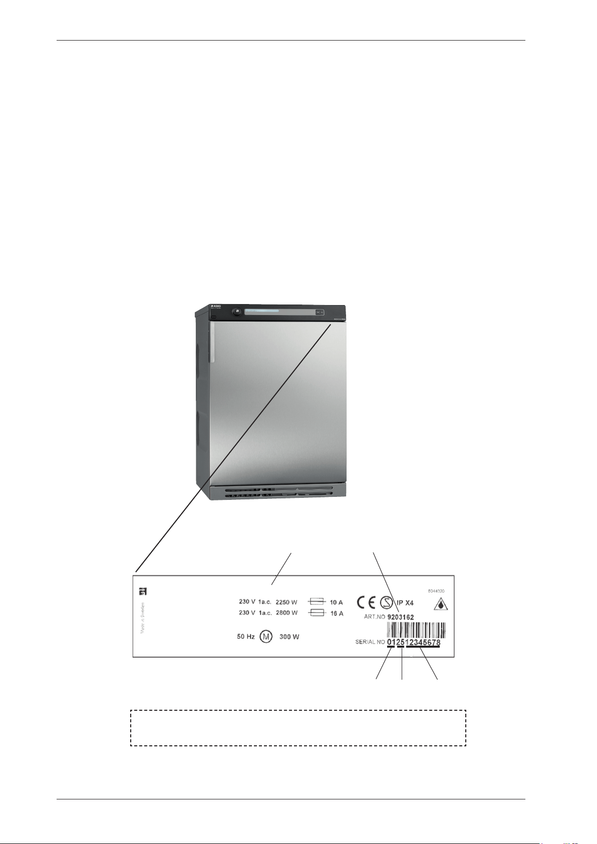
The type designation can be found on the machine plate, which is located on the inside of the
front panel by the door catch (see image below).
TYPE TD70.C
Type designation
Product number
Serial number
Year
Week
OPERATING INSTRUCTIONS
Always have the operating instructions for the machine available during service
Service Manual TD70.C
5
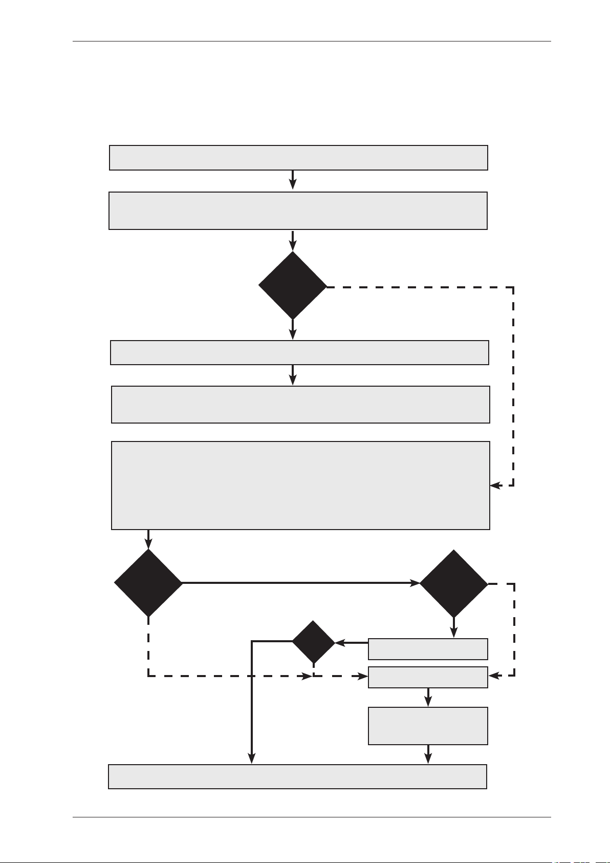
Troubleshooting strategy
Troubleshooting is an important part of the service callout, and as such we have drawn up a
troubleshooting strategy that describes, in broad terms and step by step, what you need to do to
find and diagnose faults arising in our machines.
•Askthecustomertodescribetheproblem.
•Checkwhetherthecustomer’sdescriptionmatchesthereportedfault.
•Checkthatthemachineiscorrectlyinstalled:
- Electrical connection - Drainage
- Water connection - Machine correctly levelled
Fault found?
Incorrect installation or external factors that affect performance and functionality (for
example, water pressure, electrical supply, drainage).
The machine operates normally. No deviations can be found. The customer probably needs
to be informed about proper use of the machine. If necessary, also inform the customer about
the guarantee conditions and the fact that the customer will be charged for the callout.
Yes
Opentheservicemenu:
1. Check the settings
2. Run a test cycle
3. Note any fault codes
Iftheaboveactionsdonotuncoverthefault:
•Conductgeneraltroubleshooting.UsethedocumentationavailableatServiceSaver
(service manuals, service memos, circuit diagrams and other documents).
Yes
No
Fault found?
No
Fault diagnosed?
Repair and check function/
safety.
Contact technical support
for assistance.
Carry out the actions
suggested by technical
support.
Satisfied customer!
OK?
No
Yes
No
Yes
Service Manual TD70.C
6
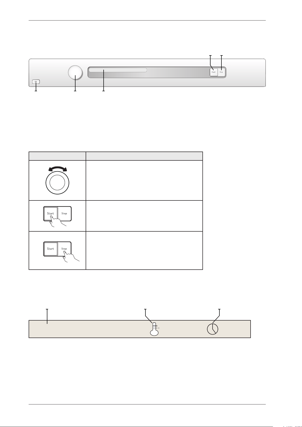
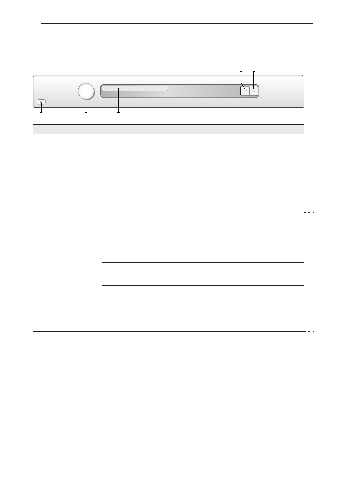
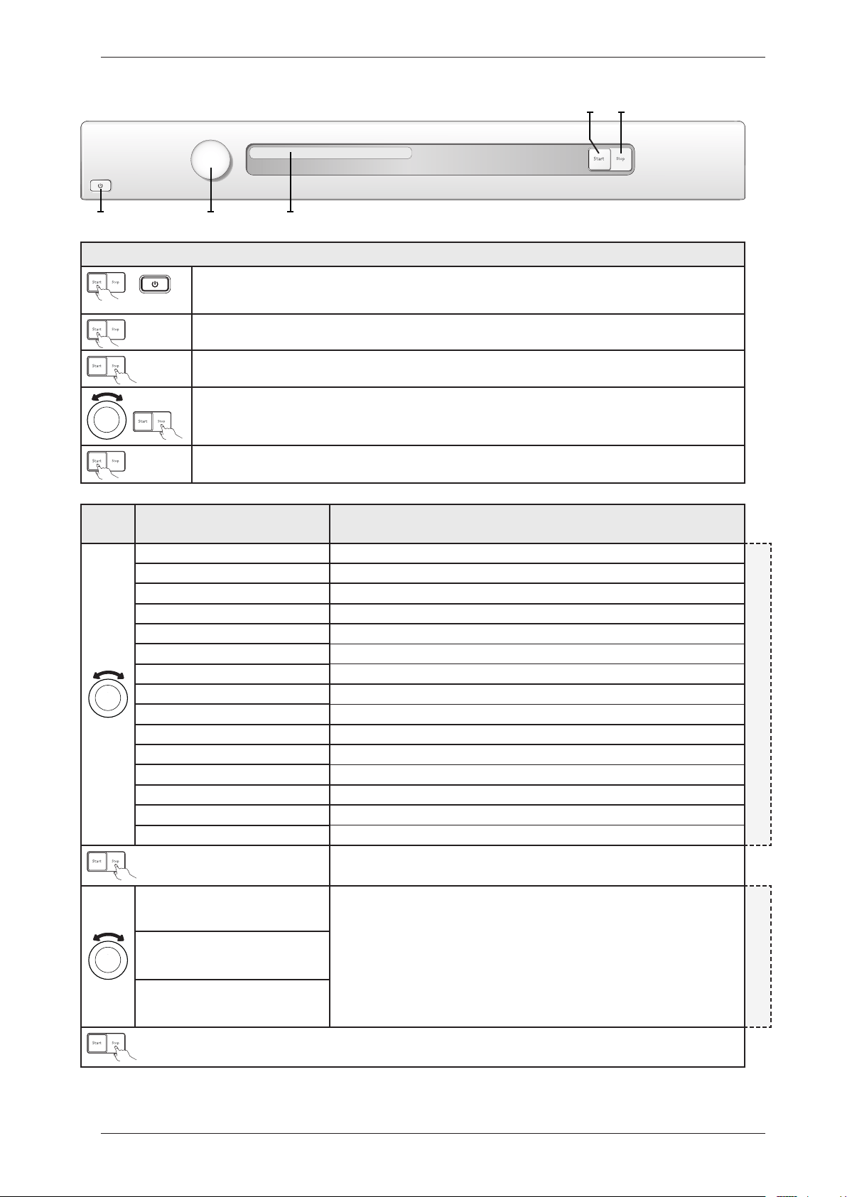
Product overview
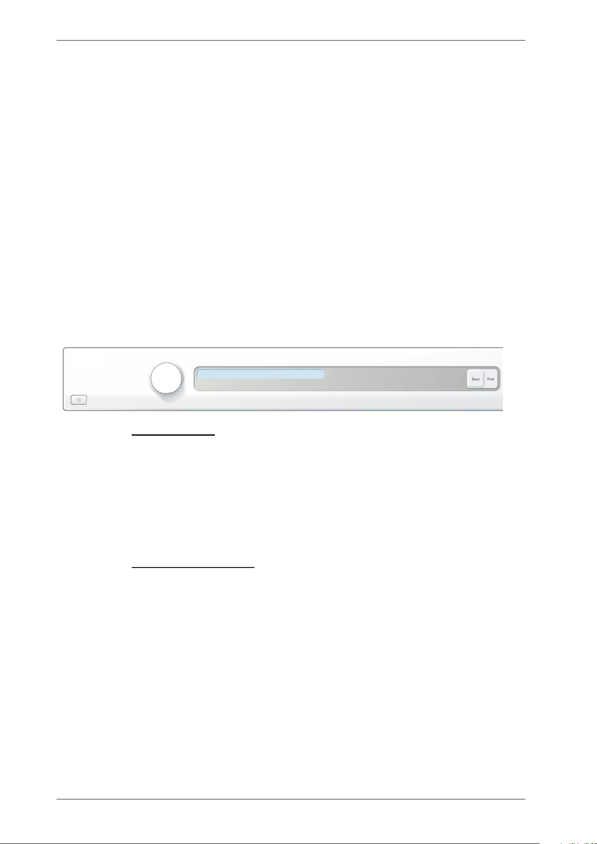
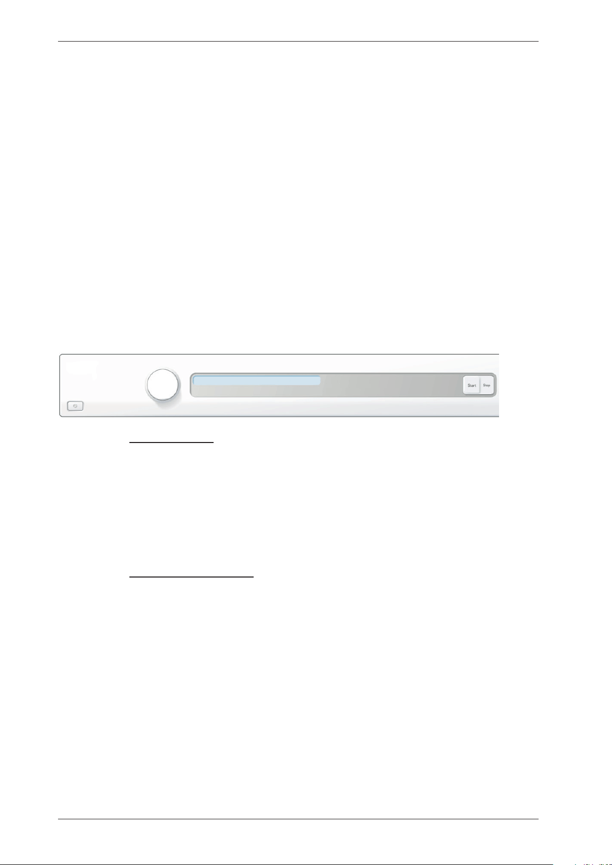
TD70.C
Programmes:A total of 7 programmes.
Settings:4 settings (Language, Child-safe, Buzzer, Heater 2)
S3
J1 DISPLAY
S2
S1
Knob and button descriptions
Turn/Push
Description
Programme selector (J1)
Turn clockwise or anti-clockwise to cycle through the different
programmes and options in the various menus.
Start button (S2)
•Startaprogramme
Stop button (S3)
•Stopprogramme(pressandholdfor3seconds).
Display description
Auto normal dry
Programme name Estimated remaining timeLow temperature
Service Manual TD70.C
7
Technical information
Height 850 mm
Width 595 mm
Depth 585 mm
Weight 43 kg (Vented)
47 kg (Condenser)
55 kg (Heat pump)
44 kg (Heating Water Circuit)
Cylinder volume 112 litres
Capacity EU 7.0 kg
US/AU 7.0 kg
Speed 50-55 rpm
Connection 1-phase 230 V, 50/60 Hz, (10 A/16 A) **
3-phase 400 V, 50/60 Hz, (10 A) **
Rated power 1950 W = 10 A** (Vented/Condenser)
3000 W = 16 A** (Vented)
2500 W = 16 A** (Condenser)
1300 W = 10 A** (Heat pump)
1950 W = 10 A** (Heating Water Circuit)
The control buttons are used to switch between 10 A and 16 A via the software.
Does not apply to Heat Pump or Heating Water Circuit.
Drum material Stainless steel
Outer panels Powder-coated and hot-galvanised sheet steel or stainless steel
Installation Stacked or freestanding
Protection class IP X4
** See type plate.
Technical data
Energy consumption and programme times
See the operating instructions for information on energy consumption and programme times.
Service Manual TD70.C
8
Component description
Components and measurement values
The specified resistance values apply at room temperature (about 20°C/68°F). Values within
±10% are considered normal.
Article no. Component Measurement value Comment
80 839 15 Motor 50 Hz,
220/240 V
Windingresistance:
cable colour red-white 26.5
Ω
cable colour red-blue 53.5
Ω
cable colour white-blue
27.0 Ω
Current:0.7A;140W;
2850 rpm
80 839 16 Motor 60 Hz,
220/240 V
Windingresistance:
cable colour red-white 26.5
Ω
cable colour red-blue 53.5
Ω
cable colour white-blue
27.0 Ω
Current:0.7A;140W;
3300 rpm
The motor is a 2-pin motor and is
directly connected to the fan for
internal air and the gearing for driving
the cylinder. On condenser dryers, the
motor also drives the fan for external air.
80 903 13 Capacitor 8 µF 50 Hz
80 903 14 Capacitor 6 µF 60 Hz
80 902 70 Capacitor heat pump 17 µF 50 Hz
80 902 71 Capacitor heat pump 60 Hz
80 821 28 Condensate pump 50 Hz
80 846 48 Condensate pump 60 Hz
80 762 02 EMC-filter with inductor The filter eliminates interference to and
from the machine.
80 833 44 Thermistor 4.8 kΩ (at 25°C) The thermistor controls temperature
regulation. If the thermistor is short-
circuited or detaches from the control
unit, the programme is stopped.
80 773 85 Thermostat 150 150°C automatic The thermostat/overheating cut-out
stops the programme if the temperature
becomes too high.
80 792 00 Thermostat 135 135°C automatic
80 902 24 Thermostat 110 110°C automatic
80 761 04 Door switch The front door triggers a door switch
which stops the programme when the
door is open. If the door has been opened
and closed during the programme the
machine must be restarted using the
Start/Stop button.
80 761 03 Microswitch float
Overflow guard
If both containers in the tumble dryer
are full the programme is stopped by
a float switch installed in the lower
container. “Over flow” is indicated on
the display.
Electrical connection Condenser 1950W/10A-
2500W/16A
Vented 1950W/10A-
3000W/16A
Heat pump 1300W/10A
Heating Water Circuit
1950W/10A
The machine is delivered as single phase
and can be switched between 10 A and 16
A. The control buttons are used to make
the switch via the software. Does not apply
to Heat Pump or Heating Water Circuit.
Service Manual TD70.C
9
Article no. Component Measurement value Comment
80 824 92 Heating element 1950 W Heater1:1950W,24.5Ω
80 915 90 Heating element 2500 W Heater1:1950W,24.5Ω
Heater2:550W,91.4Ω
80 824 91 Heating element 3000 W Heater1:1950W,24.5Ω
Heater2:1050W,45.5Ω
80 824 60 Heating element 3000 W Heater1:1950W,90.2Ω
Heater2:1050W,167.6Ω
Marine 440 V
80 824 61 Heating element 3000 W Heater1:1950W,24,5Ω
Heater2:1050W,45,5Ω
3-Phase
80 916 18 Heating element 2500 W Heater1:1950W,24,5Ω
Heater2:550W,91,4Ω
3-Phase
80 821 22 Base heat pump complete 50 Hz
80 821 23 Base heat pump complete 60 Hz
80 88 415 Reversing valve 1.9 kΩ
88 015 22
88 015 02
Control unit compl.
TD70.C
Control unit compl.
TD70.C HP/HWC
The control unit contains
microprocessors for controlling
programmes, the motor, the heating
elements etc.
80 846 49 LED-light compl. LED-technologyforthemachine’s
internal light.
Component description
Components and measurement values cont.
Service Manual TD70.C
10
Component description
Components and function description
Here we describe the function and
specification of the most important
components. Certain components are found
only in more highly specified machines or in
particular markets. See the Troubleshooting
chapter for fault and information codes.
CU (Control Unit)
The CU (Control Unit) functions as both a
control panel and a logic component. The
control panel is equipped with knobs/buttons
for selecting programmes, Start/Stop buttons
and a display. It is an integrated part of the
CU and cannot be replaced separately. The
logic component manages functions needed
for drying programmes and diagnosis. The
CU has an internal power supply for the logic
component. In the event of a fault, the CU
can diagnose a number of components and
functions, and a total of 4 fault codes can be
displayed. To facilitate troubleshooting there
is a component testing function in which the
outputs are activated according to a special
sequence.
Power supply
Mains voltage, built-in internal voltage
converter for the logic component.
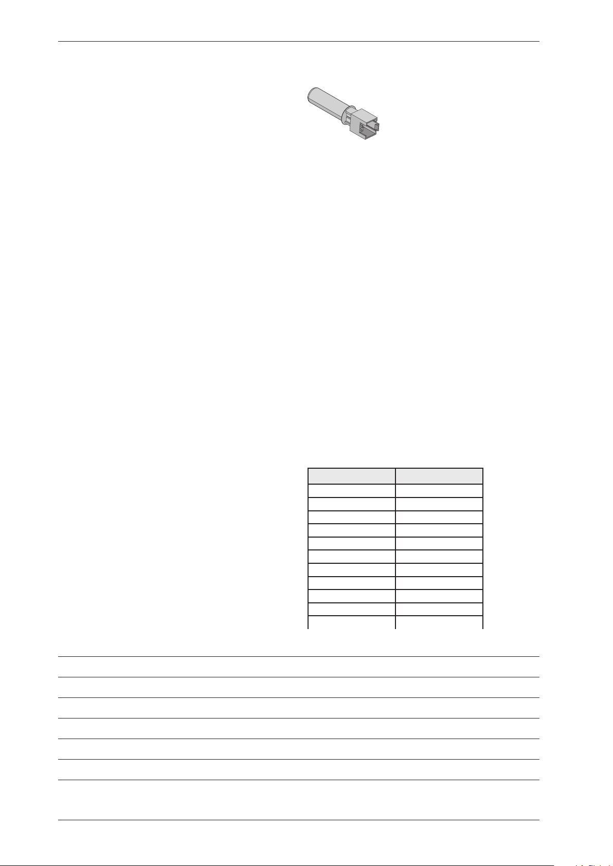
Thermistors
The thermistors are of the NTC type (Negative
Temperature Coefficient), which means their
resistance decreases as temperature increases.
Thermistor 1 is in the air duct on the front frame,
after the internal impeller. If there is an interruption
in the thermistor circuit or if it short circuits, the
drying programme stops and the display shows
“Thermistor fault”.
Purpose: Measures the temperature of the air that
has passed the load and controls the drying process
and the heating element.
Thermistor 2 is on condenser dryers located after the
condenser and on heat pump dryers located on the
evaportator pipe by the comperssor.
Purpose: Measures the temperature of the
dehumidified air, the value of which is used as a
parameter in the drying process.
Resistance values for thermistors 1 and 2
Temperature Resistance
20°C 5989
25°C 4869
30°C 3946
35°C 3197
40°C 2598
45°C 2126
50°C 1758
55°C 1471
60°C 1240
65°C 1043
70°C 857
Personal notes
Service Manual TD70.C
11
Cover plate (658 x 483 mm)
Tolerance:±1%
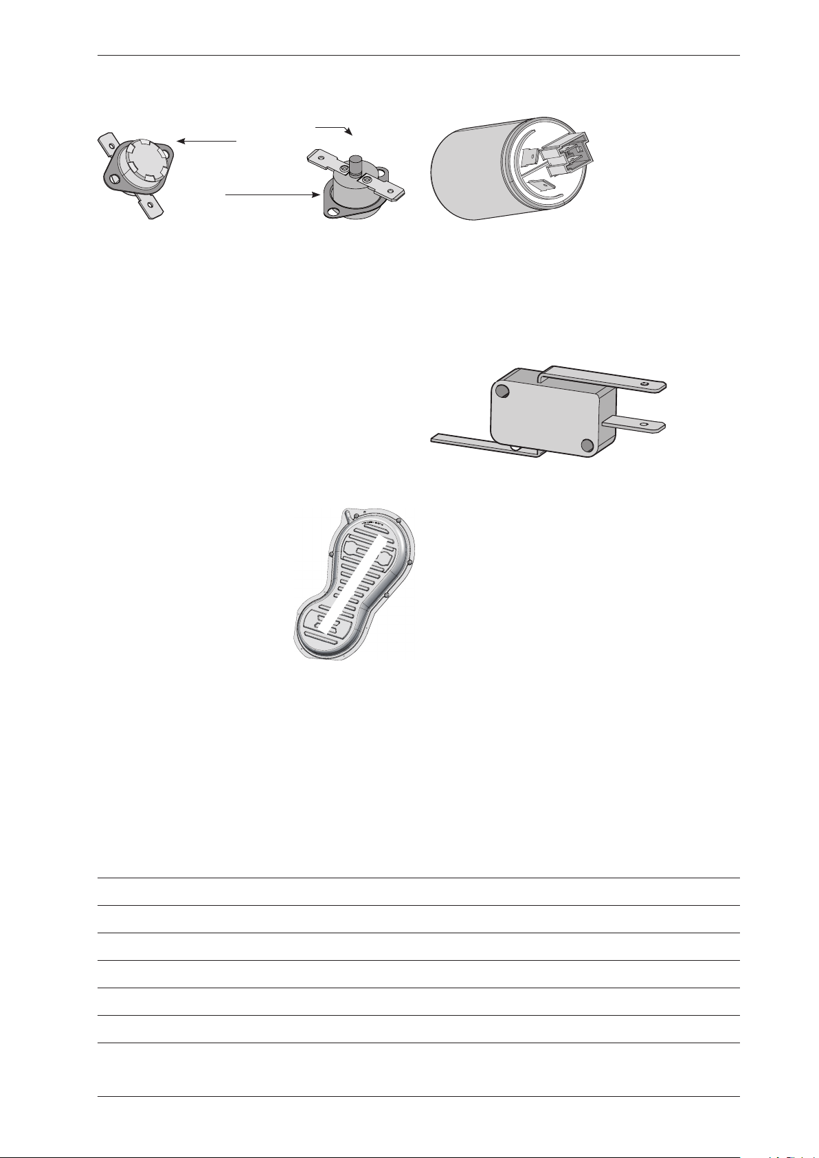
Thermostat and overheating cut-out
The thermostat is installed next to the heating
element and is used to reduce the element output
by turning it off if the ambient temperature
exceeds 135°C (±5°C) for condenser dryers and
110°C (±5°C) for others.
The machine is equipped with a overheating
cut-out, which is available in two versions, one
automatically resettable and one manual. The
overheating cut-out switches off the power supply
to all components if the temperature exceeds
150°C (±5°C) and closes the circuit once the
temperature drops below 135°C (±8°C). The
drying programme stops and must be restarted if
the overheating cut-out is triggered.
To reset the manual overheating
cut-out, the cover plate on the
machines back must be removed.
Press the button on the over-
heating cut-out for manual
reset.
The automatic overheating
cut-out resets when the
temperature drops below 135°C (±8°C) for
condenser dryer and 120°C (±5°C) for others.
Purpose: The thermostat measures
temperature and controls heating element
output. The overheating cut-out controls the
temperature and cuts the power supply if the
machine overheats.
EMC filter
The filter is installed next to the cable fasteners
where the connection cable enters the
machine. The filter consists of a number of coils,
condensers and resistors.
Purpose: To eliminate electromagnetic
interference to and from the machine.
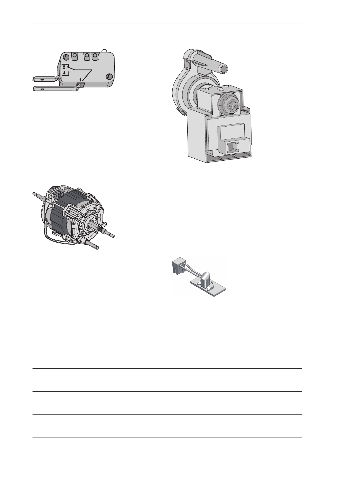
Overflow guard
The overflow guard comprises a microswitch
triggered by a float. When the lower condensed
water container becomes full the float rises
and triggers the microswitch. The microswitch
isnormallyclosed;whenactivateditopens
the circuit. When the microswitch has been
open for more than 30 seconds, the drying
programme stops and the display shows “Over
flow”. You can erase this message by turning the
programme selector or pressing the Start/Stop
buttons.
Purpose: To provide protection from any
water leaks or flooding from the machine.
Component description
Personal notes
Thermostat
Overheating cut-out
Reset
Service Manual TD70.C
12
Component description
Personal notes
Door switch
The door switch is located in a holder in the
middle of the front support and is activated by
a pin in the front door. The switch is normally
open and closes when the door is closed. If the
front door is opened during operation the CU
stops the drying programme. The programme
starts from the beginning if restarted.
Purpose: To prevent the machine from running
while the door is open.
Drying motor
The motor is at the bottom and drives the
impeller that is directly fitted to the shaft
journal. The motor is a unit with a belt
tensioner and springs and drives the drying
drum via a poly V-belt.
Purpose: To drive the impeller and drum during
the drying process.
Drainage pump (condenser dryer)
The drainage pump is located in the lower
condensed water container. The condensed
water is pumped to the condensed water
container or directly to the drain. When a
drying programme is running, the drainage
pump is activated constantly in cycles of 30
seconds ON and 210 seconds OFF.
Purpose: To pump condensed water to the
condensed water container or the drain.
Light
Certain machines have an internal light
that is activated when the door is opened.
LED technology is used to improve energy
efficiency.
Service Manual TD70.C
13
Component description
Heating element
The heating element is located in the rear section
and consists of two separate heating coils. Each
heating coil is made from resistance wire.
Purpose: To heat the drying air to the right
temperature.
1B
1A
2
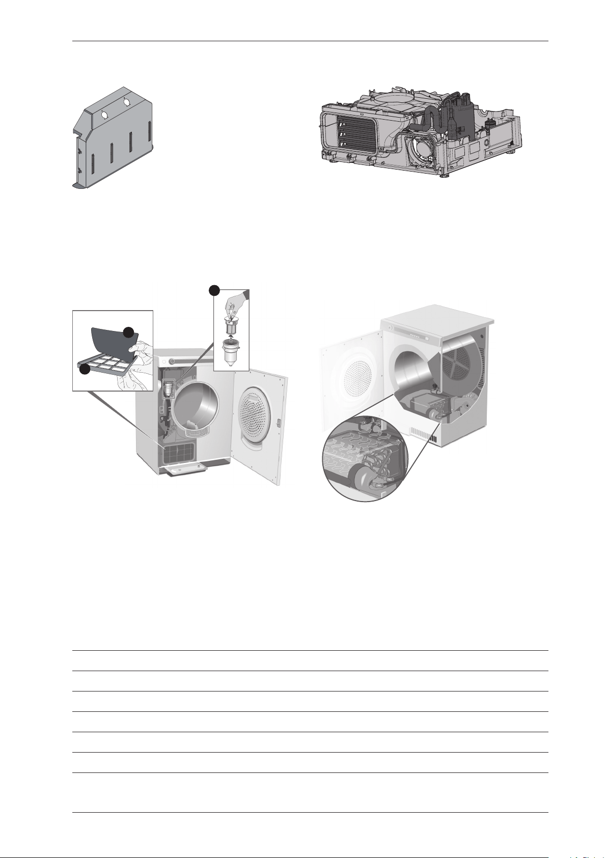
Evaporator filter and Auto filter
for Heat pump (HP)
Tumble dryers with heat pump are fitted with
evaporator filter containing a net filter (1A)
and a foam filter (1B). Some dryers can also be
fitted with auto filter, which consists of a water
filter (2), that is located under the condensed
water container.
Heat pump (HP)
Certain types of machine are fitted with heat
pump systems. These systems are closed
circuits that are replaced by replacing the
machine’sbaseplatewithanewmodule.
The function settings are adjusted in the
service menu.
Heating Water Circuit (HWC)
A certain type of machine is adapted for
connectiontothebuilding’sexistingheated
water supply (such as district heating) to
reduce energy consumption.
The function settings are adjusted in the
service menu.
Service Manual TD70.C
14

Service Manual TD70.C
15
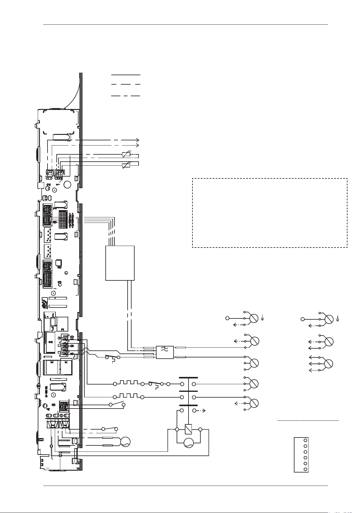
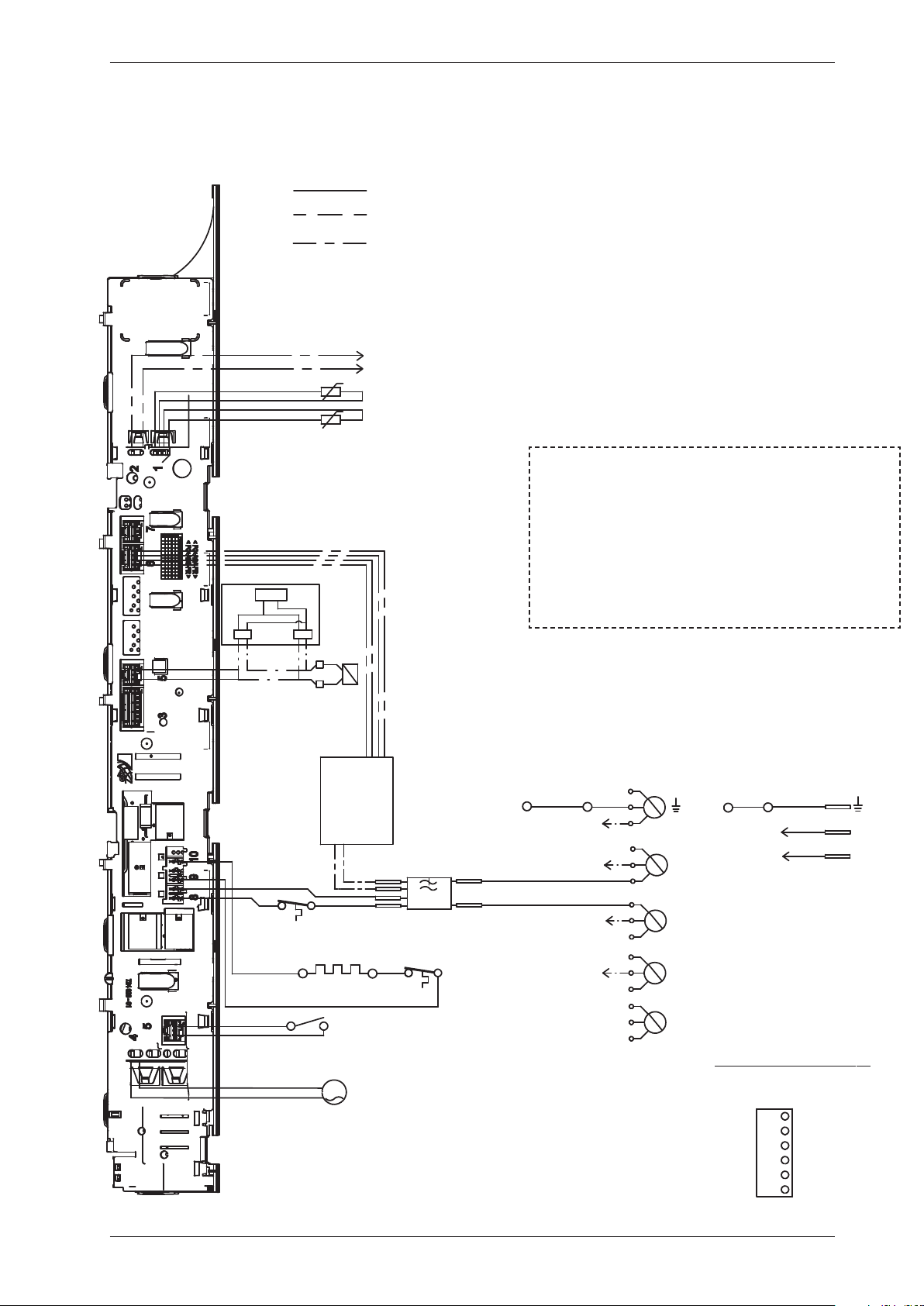
Control unit
Circuit diagram TD70.C
WIRES IN SOME MACHINES
INTERNAL CONNECTION
NTC 1
EL 550W/1050 W
F
AP
EL 1950 W
T2
DB
FB
N
L1
L3
L2
CM6
CM5
CM3
INKB
CM2
MO
T1
CM4
CM1
NTC 2 *A
WIRES IN ALL MACHINES
*A
*A CONDENSE MACHINES
CABLE POSITIONS
1: THERMISTOR
2:
COINMETER
4: MOTOR, DRAIN PUMP, FLOA
5: DOOR SWITCH
6: COMMUNICATIONS INTERFACE
8: POWER
9: HEATING ELEMENT
S1
*A
CI
RB
RA
F1
F2
R44
R43
R33
R34
R24
R23
3 Phase, 10 A
N
L1
CM6
CM3
INKB
R43/CM2
1 Phase, 16A
F1
F2
R33
PHASE
BLACK
CM1
CM2
BROWN
CM5
CM4
CM3
GROUND
BLUE
CM6
BLACK
BLUE
YELLOW-
GREEN
FROM CONTROL UNIT
NEUTRAL
RESET (FROM MOTOR)
FROM CONTROL UNIT
If coin meter is selected CM1
and CM4 needs to be closed to
start the machine
(default closed with jumper)
CON
NECTOR FOR COIN METER
CABLE POSITIONS
1: THERMISTOR
2:
COINMETER
4: MOTOR, DRAIN PUMP, FLOAT SWITCH
5: DOOR SWITCH
6: COMMUNICATIONS INTERFACE
8: POWER
9: HEATING ELEMENT
Service Manual TD70.C
16
This document must not be copied without
our written pemission, and the contents
thereof must not be imparted to a third party
nor be used for any unauthorized purpose.
Contravention will be prosecuted.
Asko Appliances AB
CIRCUIT DIAGRAM TD70.C
80 902 58 - 00
SERVICE MENU
TURN OFF POWER (S1)
WAIT FOR AT LEAST 5 SEC
HOLD S2
TURN ON POWER (S1)
PRESS S2 5 TIMES TO ENTER SERVICE MENU
PRESS STOP (S3) TO CHANGE MENU STEP
ROTATE DIAL TO CHANGE IN STEP
PRESSING START (S2) STORES AND EXITS SERVICE MENU
P, FLOAT SWITCH
TERFACE
RESISTANCES AT ROOM TEMPERATURE (CA. 20°C/68°F)
VALUES WITH +/-10% ARE REGARDED AS NORMAL
COMPONENT
F: RADIO INTERFERENCE SUPPRESSION FILTER 680K Ohm
NTC 1: THERMISTOR 1 4 - 6 K Ohm
NTC 2: THERMISTOR 2: 4 - 6 K Ohm
AP: DRAIN PUMP: 111 Ohm
EL: HEATING ELEMENT 1050W 45.3 Ohm
EL: HEATING ELEMENT 1950W 20.5 Ohm
MO: MOTOR
T1: THERMOSTAT, OVERHEATING (HEATER)
T2: THERMOSTAT, OVERHEATING (HEATER)
FB: FLOAT SWITCH
DB: DOOR SWITCH
CI: COMMUNICATIONS INTERFACE
S2 S3
S1
USER SETTINGS MENU
TURN OFF POWER (S1)
WAIT FOR AT LEAST 5 SEC
HOLD S3
TURN ON POWER (S1)
PRESS S3 5 TIMES TO ENTER MENU
2011-07-07
IT
OM MOTOR)
IT
Service Manual TD70.C
17
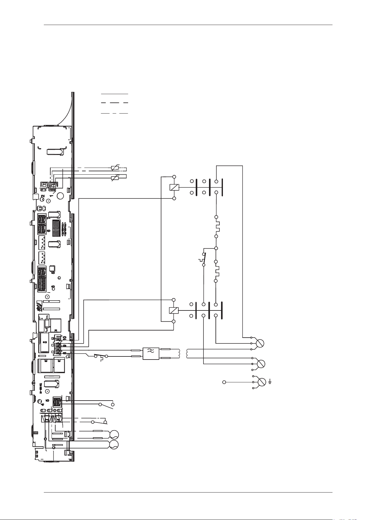
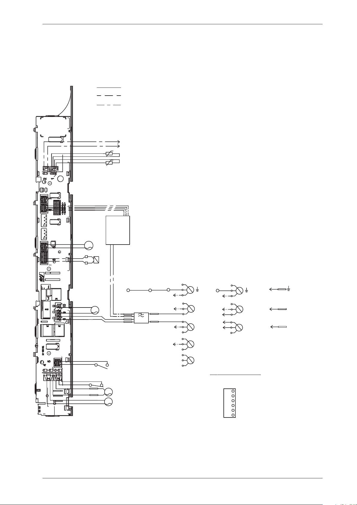
Control unit
Circuit diagram TD70.C Marine
WIRES IN SOME MACHINES
INTERNAL CONNECTION
NTC 1
EL 1050 W
F
AP
EL 1950 W
T2
DB
FB
L1
L2
MO
T1
NTC 2 *A
WIRES IN ALL MACHINES
*A
*A CONDENSE MACHINES
CABLE POSITIONS
1: THERMISTOR
4: MOTOR, DRAIN PUMP, FLOAT SWITCH
5: DOOR SWITCH
6: COMMUNICATIONS INTERFACE
7: COINMETER
8: POWER
9: HEATING ELEMENT
*A
F1
F2
RB
RA
R44
R43
RB
RA
R44
R43
R33
R34
T
Blue
Orange
MO
Service Manual TD70.C
18

This document must not be copied without
our written pemission, and the contents
thereof must not be imparted to a third party
nor be used for any unauthorized purpose.
Contravention will be prosecuted.
Asko Appliances AB
CIRCUIT DIAGRAM TD70.C
80 902 59 - 01
SER
VICE M
EN
U
TURN OFF POWER (S1)
WAIT FOR AT LEAST 5 SEC
HOLD S2
TURN ON POWER (S1)
PRESS S2 5 TIMES TO ENTER SERVICE MENU
PRESS STOP (S3) TO CHANGE MENU STEP
ROTATE DIAL TO CHANGE IN STEP
PRESSING START (S2) STORES AND EXITS SERVICE MENU
RESISTANCES AT ROOM TEMPERATURE (CA. 20°C/68°F)
VALUES WITH +/-10% ARE REGARDED AS NORMAL
COMPONENT
F: RADIO INTERFERENCE SUPPRESSION FILTER 680K Ohm
NTC 1: THERMISTOR 1 4 - 6 K Ohm
NTC 2: THERMISTOR 2: 4 - 6 K Ohm
AP: DRAIN PUMP: 111 Ohm
EL: HEATING ELEMENT 1050W 167,6 Ohm
EL: HEATING ELEMENT 1950W 90,2 Ohm
MO: MOTOR
T1: THERMOSTAT, OVERHEATING (HEATER)
T2: THERMOSTAT, OVERHEATING (HEATER)
FB: FLOAT SWITCH
DB: DOOR SWITCH
T: TRANSFORMER
S2 S3
S1
USER
SETTIN
GS M
EN
U
TURN OFF POWER (S1)
WAIT FOR AT LEAST 5 SEC
HOLD S3
TURN ON POWER (S1)
PRESS S3 5 TIMES TO ENTER MENU
2012-09-10
Service Manual TD70.C
19
Control unit
Circuit diagram TD70.C UL (only USA)
WIRES IN SOME MACHINES
INTERNAL CONNECTION
NTC 1
EL 1050 W
F
AP
EL 1950 W
T2
DB
FB
N
L3
L2
L1
CM6
CM5
CM3
CM2
MO
T1
CM4
CM1
NTC 2 *A
WIRES IN ALL MACHINES
*A
*A CONDENSE MACHINES
CABLE POSITIONS
1: THERMISTOR
2:
COINMETER
4: MOTOR, DRAIN PUMP, FLOA
5: DOOR SWITCH
6: COMMUNICATIONS INTER
8: POWER
9: HEATING ELEMENT
CI
F1
F2
CONNECTION BOX
L
N
L
L1 2
L1 2
L2 2
L2 2
RECL
RECL
RECG
*A
PHASE
BLACK
CM1
CM2
BROWN
CM5
CM4
CM3
GROUND
BLUE
CM6
BLACK
BLUE
YELLOW-
GREEN
FROM CONTROL UNIT
FROM CONTROL UNIT
If coin meter is selected CM1
and CM4 needs to be closed to
start the machine
(default closed with jumper)
CONNECTOR FOR COIN METER
PHASE
CABLE POSITIONS
1: THERMISTOR
2:
COINMETER
4: MOTOR, DRAIN PUMP, FLOAT SWITCH
5: DOOR SWITCH
6: COMMUNICATIONS INTERFACE
8: POWER
9: HEATING ELEMENT
Service Manual TD70.C
20
This document must not be copied without
our written pemission, and the contents
thereof must not be imparted to a third party
nor be used for any unauthorized purpose.
Contravention will be prosecuted.
Asko Appliances AB
CIRCUIT DIAGRAM TD70.C US/CA
80 902 60 - 01
SERVICE MENU
TURN OFF POWER (S1)
WAIT FOR AT LEAST 5 SEC
HOLD S2
TURN ON POWER (S1)
PRESS S2 5 TIMES TO ENTER SERVICE MENU
PRESS STOP (S3) TO CHANGE MENU STEP
ROTATE DIAL TO CHANGE IN STEP
PRESSING START (S2) STORES AND EXITS SERVICE MENU
P, FLOAT SWITCH
IONS INTERFACE
RESISTANCES AT ROOM TEMPERATURE (CA. 20°C/68°F)
VALUES WITH +/-10% ARE REGARDED AS NORMAL
COMPONENT
F: RADIO INTERFERENCE SUPPRESSION FILTER 680K Ohm
NTC 1: THERMISTOR 1 4 - 6 K Ohm
NTC 2: THERMISTOR 2: 4 - 6 K Ohm
AP: DRAIN PUMP: 111 Ohm
EL: HEATING ELEMENT 1050W 45.3 Ohm
EL: HEATING ELEMENT 1950W 20.5 Ohm
MO: MOTOR
T1: THERMOSTAT, OVERHEATING (HEATER)
T2: THERMOSTAT, OVERHEATING (HEATER)
FB: FLOAT SWITCH
DB: DOOR SWITCH
CI: COMMUNICATIONS INTERFACE
S2 S3
S1
USER SETTINGS MENU
TURN OFF POWER (S1)
WAIT FOR AT LEAST 5 SEC
HOLD S3
TURN ON POWER (S1)
PRESS S3 5 TIMES TO ENTER MENU
2011-09-15
IT
IT
Service Manual TD70.C
21
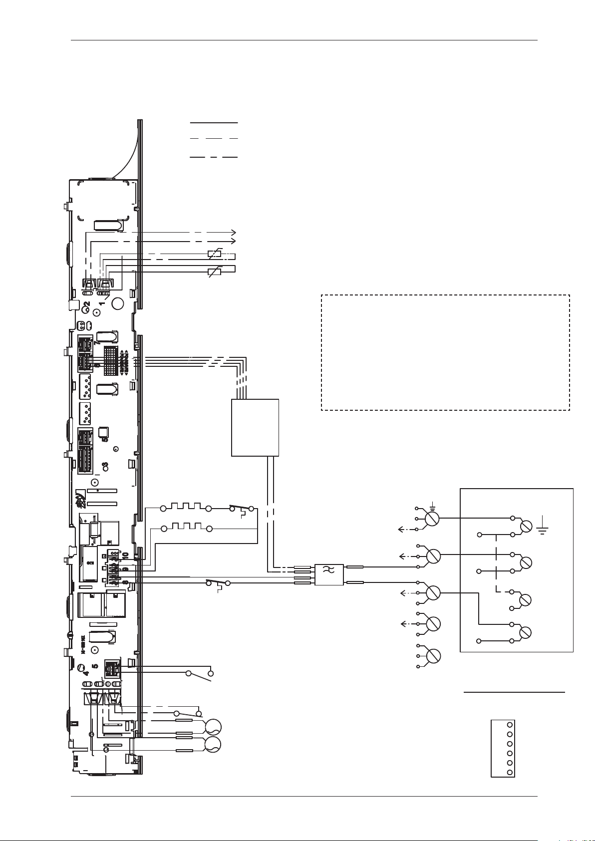
Control unit
Circuit diagram TD70.C HWC
WIRES IN SOME MACHINES
INTERNAL CONNECTION
NTC 1
F
EL 1950 W
T2
DB
N
L1
L3
L2
CM6
CM5
CM3
INKB
CM2
MO
T1
CM4
CM1
NTC 2
WIRES IN ALL MACHINES
CABLE POSITIONS
1: THERMISTOR
2:
COINMETER
4: MOTOR, DRAIN PUMP, FLOA
5: DOOR SWITCH
6: COMMUNICATIONS INTER
8: POWER
9: HEATING ELEMENT
CI
F1
F2
3 Phase
F1
F2
MV
INKB
L
N
1 Phase
MO
MO
PHASE
BLACK
CM1
CM2
BROWN
CM5
CM4
CM3
GROUND
BLUE
CM6
BLACK
BLUE
YELLOW-
GREEN
FROM CONTROL UNIT
NEUTRAL
FROM CONTROL UNIT
If coin meter is selected CM1
and CM4 needs to be closed to
start the machine
(default closed with jumper)
CON
NECTOR FOR COIN METER
Relay board
CABLE POSITIONS
1: THERMISTOR
2:
COINMETER
4: MOTOR, DRAIN PUMP, FLOAT SWITCH
5: DOOR SWITCH
6: COMMUNICATIONS INTERFACE
8: POWER
9: HEATING ELEMENT
Service Manual TD70.C
22
This document must not be copied without
our written pemission, and the contents
thereof must not be imparted to a third party
nor be used for any unauthorized purpose.
Contravention will be prosecuted.
Asko Appliances AB
CIRCUIT DIAGRAM TD70.C HWC
80 902 89 - 00
SERVICE MENU
TURN OFF POWER (S1)
WAIT FOR AT LEAST 5 SEC
HOLD S2
TURN ON POWER (S1)
PRESS S2 5 TIMES TO ENTER SERVICE MENU
PRESS STOP (S3) TO CHANGE MENU STEP
ROTATE DIAL TO CHANGE IN STEP
PRESSING START (S2) STORES AND EXITS SERVICE MENU
P, FLOAT SWITCH
TERFACE
RESISTANCES AT ROOM TEMPERATURE (CA. 20°C/68°F)
VALUES WITH +/-10% ARE REGARDED AS NORMAL
COMPONENT
F: RADIO INTERFERENCE SUPPRESSION FILTER 680K Ohm
NTC 1: THERMISTOR 1 4 - 6 K Ohm
NTC 2: THERMISTOR 2: 4 - 6 K Ohm
EL: HEATING ELEMENT 1950W 20.5 Ohm
MO: MOTOR
T1: THERMOSTAT
T2: THERMOSTAT,
DB: DOOR SWITCH
CI: COMMUNICATIONS INTERFACE
MV: MAGNETIC VALVE 866 Ohm
S2 S3
S1
USER SETTINGS MENU
TURN OFF POWER (S1)
WAIT FOR AT LEAST 5 SEC
HOLD S3
TURN ON POWER (S1)
PRESS S3 5 TIMES TO ENTER MENU
2011-07-07
IT
IT
Service Manual TD70.C
23
Circuit diagram TD70.C HP
Control unit
WIRES IN SOME MACHINES
INTERNAL CONNECTION
NTC 1
F
AP
DB
FB
N
L1
L3
L2
CM6
CM5
CM3
INKB
CM2
MO
CM4
CM1
NTC 2
WIRES IN ALL MACHINES
CABLE POSITIONS
1: THERMISTOR
2:
COINMETER
4: MOTOR, DRAIN PUMP, FLOAT SWITCH
5: DOOR SWITCH
6: COMMUNICATIONS INTERFACE
8: POWER
9: HEATING ELEMENT
CI
F1
F2
3 Phase, 10 A
N
L1
CM6
CM3
INKB
1 Phase, 10A
No coin meter
F1
F2
CO
CM5
SV
PHASE
BLACK
CM1
CM2
BROWN
CM5
CM4
CM3
GROUND
BLUE
CM6
BLACK
BLUE
YELLOW-
GREEN
FROM CONTROL UNIT
NEUTRAL
FROM CONTROL UNIT
If coin meter is selected CM1
and CM4 needs to be closed to
start the machine
(default closed with jumper)
CON
NECTO
R FOR COIN ME
TER
PHASE
FA
L
N
MO
CO
MO
F1
F2
1 Phase, 10A
Service Manual TD70.C
24

This document must not be copied without
our written pemission, and the contents
thereof must not be im
parted to a third party
nor be used for any unauthorized purpose.
Contravention will be prosecuted.
Asko Appliances AB
CIRCUIT DIAGRAM TD70.C HP
80 902 90 - 02
S
ERVICE MENU
TURN OFF POWER (S1)
WAIT FOR AT LEAST 5 SEC
HOLD S2
TURN ON POWER (S1)
PRESS S2 5 TIMES TO ENTER SERVICE MENU
PRESS STOP (S3) TO CHANGE MENU STEP
ROTATE DIAL TO CHANGE IN STEP
PRESSING START (S2) STORES AND EXITS SERVICE MENU
RESISTANCES AT ROOM TEMPERATURE (CA. 20°C/68°F)
VALUES WITH +/-10% ARE REGARDED AS NORMAL
COMPONENT
F: RADIO INTERFERENCE SUPPRESSION FILTER 680K Ohm
NTC 1: THERMISTOR 1 4 - 6 K Ohm
NTC 2: THERMISTOR 2: 4 - 6 K Ohm
AP: DRAIN PUMP: 111 Ohm
CO: COMPRESSOR
MO: MOTOR
FB: FLOAT SWITCH
DB: DOOR SWITCH
CI: COMMUNICATIONS INTERFACE
SV: SWITCHING VALVE
FA: FAN
S2 S3
S1
U
SER SETTINGS MENU
TURN OFF POWER (S1)
WAIT FOR AT LEAST 5 SEC
HOLD S3
TURN ON POWER (S1)
PRESS S3 5 TIMES TO ENTER MENU
2012-04-19
Service Manual TD70.C
25
Fault indicators
In the case of a fault the following fault indicators are shown on the display.
Troubleshooting
S3
J1 DISPLAY
S2
S1
Display Cause Action
Over flow fault, Overflow
Fault, Over flow fault,
Överfyllnad, Overløbsfejl,
Overflom, Ylitulviminen,
Trop plein, Überlauf,
Troppo pieno, Desborde,
Пeрeлив вoды, Te veel
water
The microswitch is opened when a
full condensed water tank is detected.
Detection begins 30 seconds after the
programme starts. If the microswitch is
open >30 seconds the programme cycle
is stopped.
Check whether the customer has:
•Emptiedthetankandrestartedthe
machine.
Service action:
•Cleanhosesandcheckvoltageand
resistance of drainage pump.
•Checkthattheoathasnotgot
“stuck” and check the function of the
microswitch.
The auto filter is clogged, defective or
the auto filter/sealing is improper fitted.
Check whether the customer has:
•Cleanedtheautolterandinstalledthe
auto filter/sealing properly.
Service action:
•Replacetheautolterand/orthe
sealing.
HP (heat pump)
Defective or improper installed anti-
siphon valve.
Service action:
•Cleanthehoseandreplacethe
anti-siphon valve.
The reversing valve is clogged or
defective.
Service action:
•Cleantheautolterandreplace
the anti-siphon valve.
Hoses improper installed after service. Service action:
•Checkhoseinstallation.
Max Program Time,
Max program time ,
Maximal programtid,
Maksimal programtid,
Maks programtid, Max
ohjelma-aika, Durée maxi
prog., Tijd overschreden,
Tempo max. progr.,
Duración máx prog,
Пpeвышeниe вpeмeни,
Max. Programmzeit
The programme cycle time exceeds 200
minutes. The cycle is stopped and the
programme is reset.
High ambient temperature combined
with low heater output and low
drying temperature leads to poor
condensation formation.
Poor condensation due to blocked
external air
Check whether the customer has:
•Triedspinningatahigher
speed.
•Hadthemachineswitchedofffor30
minutes before restarting.
•Goodventilationintheroom.
Service action:
•Ensurethattheexternalairhasfree
passage.
Service Manual TD70.C
26
Display Cause Action
Thermistor fault,
Thermistor Fault,
Thermistor fault,
Termistorfel, Termostat
fejl, Termistor,
Termistorivika, Défaut
, Termistorfehler,
Termistore , Fallo ,
Teрмистoр, Temp. sensor
fout
1. Thermistor circuit open
2. Thermistor malfunction
Service action:
Check the thermistor. Replace if
necessary.
Clean condenser, Rengör
kondensor, Rens kon.
sator, Rens kon.sator,
Puhdista lauhdutin,
Nettoyage condenseur,
Reinigen kondensor, Pulizia
condensatore, Limpiar
condensador, Oчистить
кoндeнсaтoр, Kondenser
reinigen
1. Displayed according to the interval set
in the service menu.
Check whether the customer has:
•Cleanedthecondenser/evaporator
and filter.
•Cleanedtheotherairpassages.
Clean Lint Filter, Clean
Lint Filter, Rengör filtret,
Rengør fnugfilter, Rens
filter, Puhdista sihti,
Nettoyage filtre, Reinig
filter, Pulizia filtro, Limpie
el filtro, Oчистить фильтp,
Sieb reinigen
1. Displayed according to the interval set
in the service menu.
Check whether the customer has:
•Cleanedthelintlter.
Clean auto filter, Rengör
autofilter, Rens aut. filter,
Rengjøring autofilter, Puhd.
autom. suodatin, Nett. filtre
auto, Auto. filter reinigen,
Pulizia filtro auto, Limpiar
el autofiltro, Очистите
автофильтр, Autofilter
reinigen
1. Displayed according to the interval set
in the service menu.
Check whether the customer has:
•Cleanedthewaterlter.
HP (heat pump)
Clean filter, Rengör filter,
Rens filter, Rengjøring
filter, Puhd. suodatin,
Nett. Filtre, Filter reinigen,
Pulizia filtro, Limpiar el
filtro, Очистите фильтр,
Filter reinigen
1. Displayed according to the interval set
in the service menu.
Check whether the customer has:
•Cleanedtheevaporatorlter(net filter
+ foam filter) and the evaporator.
HP (heat pump)
After carrying out corrective actions as above, reset the fault indication on the display by switching off the machine at
the main power switch.
Fault indicators cont.
Troubleshooting
Service Manual TD70.C
27
Fault symptom Cause Action
The machine will not
start.
The outer door is not properly closed. •Checkthatthedoorpinisactivatingthe
door switch.
The machine is not supplied with power. •Checkthefusesandconnections.
The machine stops. The manuel overheating cut-out has
tripped. Not heat pump dryers (HP).
Service action:
•Cleaninternalimpeller,condenser,air
ducts and element.
•Checktheseals.
The overheating cut-out in the motor
has been tripped.
•Cleanandcheckthemotor.
•Ifnecessary,replacemotor.
Defective control unit •Replacecontrolunit.
The washing does not
get dry.
Air leakage through the door seals is
affecting the drying results.
•Checkthesealingstrips.
Air leakage around the motor shaft is
affecting the drying results.
•Checkthesealaroundthemotorshaft.
Defective rear thermistor •Replacethermistor.
Defective control unit •Replacecontrolunit.
Drying is uneven. Mixing various types of items can lead
to uneven drying results.
Information to customer:
•Ensurethatdifferenttypesofitemsare
not dried in the same load. Remove any
dry items.
How full the machine is affects the
drying results.
Information to customer:
•Checkthatthemachineisnotoverlled.
Remove some of the washing if necessary.
Tumble-drying takes
too long.
The lint filter is blocked. Information to customer:
•Cleanthelintlter.
The condenser unit is blocked. Information to customer:
•Cleanthecondenser.
Thewashingmachine’sspinningaffects
drying.
Information to customer:
•Spinataminimumof800rpm.
The machine is in a room with poor
ventilation.
Information to customer:
•Opendoorstoadjacentrooms.
The evacuation hose is too long,
blocked or bent.
Information to customer:
•Trytomakethehoselengthasshortas
possible with as gentle bends as possible.
The evaporator filter (net filter + foam
filter) and the evaporator is clogged.
Information to customer:
•Cleantheevaporatorlter(netlter
+ foam filter) and the evaporator.
HP (heat pump)
Defective evaporator filter (net filter +
foam filter).
•Replacethenetlterand/orfoamlter.
The auto filter is clogged. Information to customer:
•CleantheAutolter.
Defective magnetic coil. •Replacethedefectmagneticcoil.
Other faults
Troubleshooting
If the tumble dryer does not work, you should first check whether this is due to a simple fault,
something that the customer can rectify.
Service Manual TD70.C
28
Fault symptom Cause Action
The machine is leaking
water.
Improper installed auto filter and/or
sealing
Information to customer:
•Checkthattheautolterandthesealing
is proper installed.
HP (heat pump)
Defective auto filter and/or sealing Information to customer:
•HandletheautoFilterandsealing
carefully when cleaning.
Service action:
•Replacetheautolterand/orthesealing.
The anti-siphon valve hose connection
improper installed
•Fitthehoseconnectiontothereturn
valve properly.
Defective hose connection to the
anti-siphon valve
•Replacetheanti-siphonvalvehose
connection.
Other faults cont.
Troubleshooting
Service Manual TD70.C
29
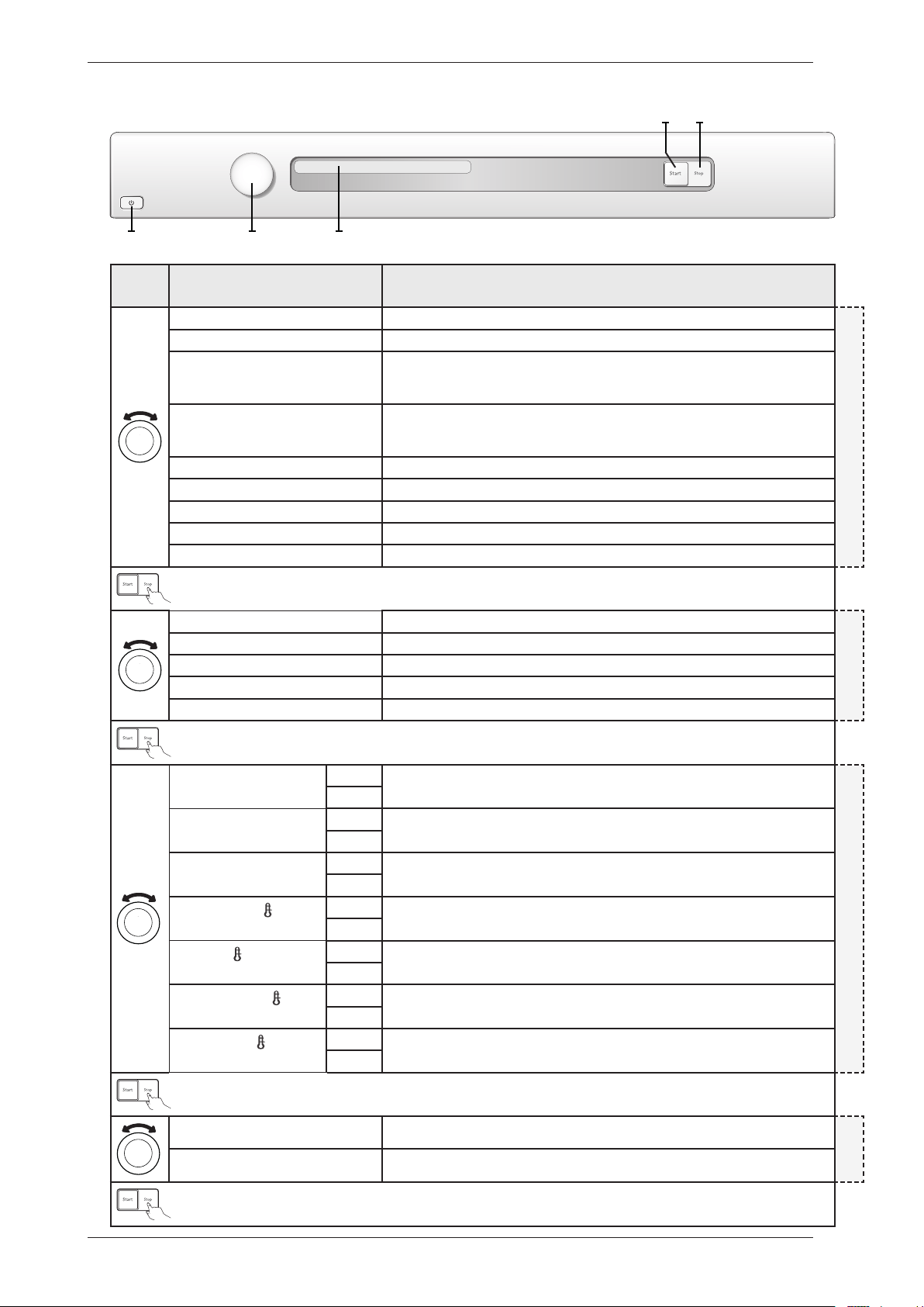
Service menu
Turn/
Push
Display Comments/instructions
SP:xxxxDate the software was programmed (Year_Week)
TRACKINGDATA
CM:xxxxDate of manufacture of the control unit (Year_Week)
SV:xxxxxxxxxSoftware version number
NCP0:xxxxxxxxxTotal number of cycles run
NCP1:xxxxxxxxxNumber of cycles run for Programme 1
NCP2:xxxxxxxxxNumber of cycles run for Programme 2
NCP3:xxxxxxxxxNumber of cycles run for Programme 3
NCP4:xxxxxxxxxNumber of cycles run for Programme 4
NCP5:xxxxxxxxxNumber of cycles run for Programme 5
NCP6:xxxxxxxxxNumber of cycles run for Programme 6
NCP7:xxxxxxxxxNumber of cycles run for Programme 7
NCP8:xxxxxxxxxNumber of cycles run for Programme 8
NCP9:xxxxxxxxxNumber of cycles run for Programme 9
NCP10:xxxxxxxxxNumber of cycles run for Programme 10
NCP11:xxxxxxxxxNumber of cycles run for Programme 11
”Fault No. of cycles(1)” Last three faults and number of cycles (when the fault occurred) shown. A total reset
deletes the fault indications from the system. If the same fault recurs at different times,
this is shown, but only once in the list.
FAILURE REEDD OUT
”Fault No. of cycles (2)”
”Fault No. of cycles (3)”
Opening the service menu
+
Check that the machine is switched off. Otherwise switch off the main power by pressing the main power switch
(S1).
Press and hold the Start button (S2) while turning on the main power with the main power switch (S1).
Press the Start button (S2) 5 times within 5 seconds. The service menu is now activated, as seen in the display
window. The service menu can be closed by turning off the power with the main power switch (S1).
Press the Stop button (S3) to navigate the menu system step by step.
Turn the programme selector (J1) to make selections from the menus.
Confirm the selection and continue to the next menu by pressing the Stop button (S3).
Press the Start button (S2) to confirm the settings and exit the service menu.
x 5
Panel key: S = Push button, J = Knob
S3
J1 DISPLAY
S2
S1
Service Manual TD70.C
30
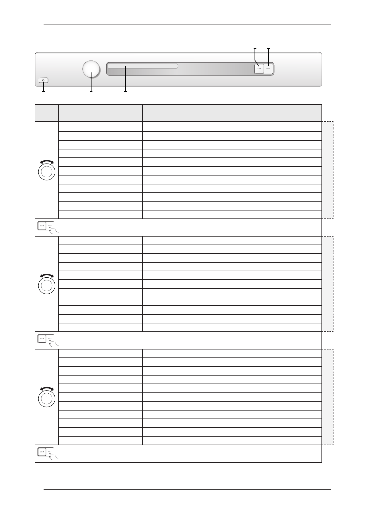
Service menu cont.
Turn/
Push
Display Comments/instructions
Test No component tested
DIAGNOSTICS
Test motor The motor runs at normal speed
Test heater 1 The motor runs at normal speed. Heating element 1 is switched on and off by the CU
depending on the values registered by thermistors 1 and 2. Max. temp. 70°C. (Only if
setting for heat pump is Heat Pump Off )
Test heater 2 The motor runs at normal speed. Heating element 2 is switched on and off by the CU
depending on the values registered by thermistors 1 and 2. Max. temp. 70°C. (Only for
condenser and vented machines and where setting for steam is Steam Off)
Testing compressor Temperature sequence on (only machines with heat pump)
Testing switching valve Switching valve on (only machines with heat pump)
Testing fan/HWC Fan/Valve on (Fan only for machines with heat pump and Valve only for HWC)
Test drain The condensed water pump starts (only condenser machines and heat pump)
Test buzzer Buzzer on continuously
Dry level 0 Drying time extended by 0, default setting
DRY LEVEL
Dry level +5 Drying time extended by 5 min
Dry level +10 Drying time extended by 10 min
Dry level +15 Drying time extended by 15 min
Dry level +20 Drying time extended by 20 min
Auto extra dry Off Setting to make Programme 1 - Auto extra dry selectable/non-selectable in the
programme menu.
BLOCKPROGRAMS
On
Auto dry Off Setting to make Programme 2 - Auto dry selectable/non-selectable in the programme
menu.
On
Auto normal dry Off Setting to make Programme 3 - Auto normal dry selectable/non-selectable in the
programme menu.
On
Auto extra dry
Off Setting to make Programme 4 - Auto extra dry, low temperature selectable/non-
selectable in the programme menu.
On
Auto dry
Off Setting to make Programme 5 - Auto dry, low temperature selectable/non-selectable
in the programme menu.
On
Auto normal dry
Off Setting to make Programme 6 - Auto normal dry, low temperature selectable/non-
selectable in the programme menu.
On
Auto iron dry
Off Setting to make Programme 7 - Auto iron dry, low temperature selectable/non-
selectable in the programme menu.
On
Coin Off Setting for coin operations Off, default setting
COIN
Coin On Setting for coin operations On
S3
J1 DISPLAY
S2
S1
Service Manual TD70.C
31
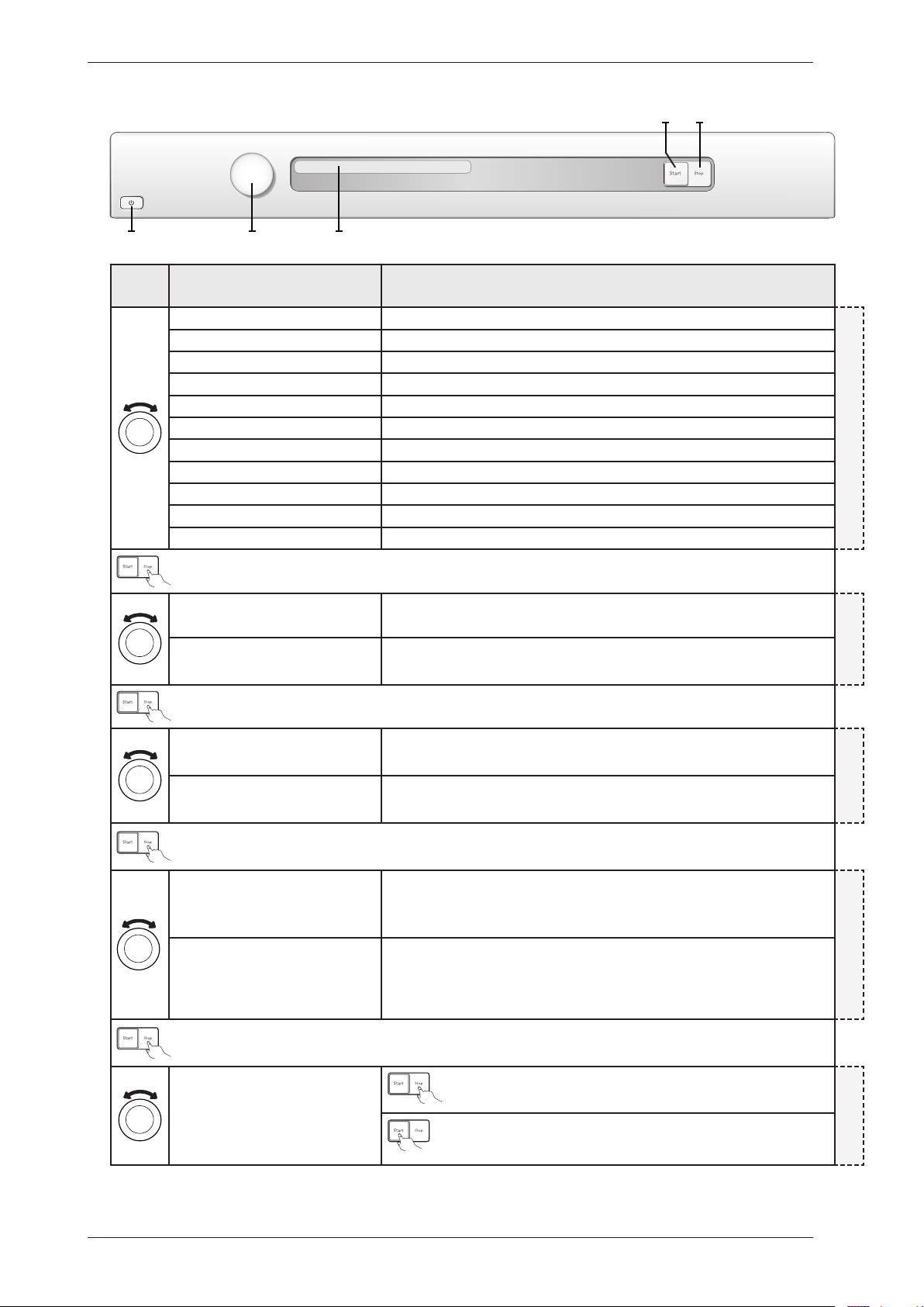
Service menu cont.
Turn/
Push
Display Comments/instructions
Filter Interval 2 Interval for indication ”Clean filter”, default setting (every 2nd cycle)
CLE AN FILTER
Filter Interval 3 Interval for indication ”Clean filter” (every 3rd cycle)
Filter Interval 4 Interval for indication ”Clean filter” (every 4th cycle)
Filter Interval 5 Interval for indication ”Clean filter” (every 5th cycle)
Filter Interval 6 Interval for indication ”Clean filter” (every 6th cycle)
Filter Interval 7 Interval for indication ”Clean filter” (every 7th cycle)
Filter Interval 8 Interval for indication ”Clean filter” (every 8th cycle)
Filter Interval 9 Interval for indication ”Clean filter” (every 9th cycle)
Filter Interval 10 Interval for indication ”Clean filter” (every 10th cycle)
Filter Interval 1 Interval for indication ”Clean filter” (every cycle)
Filter Interval 0 Interval for indication ”Clean filter” (not shown)
Condense Interval 0 Interval for indication ”Clean condense”, default setting (not shown)
CLE AN CONDENSE (Condenser)
Condense Interval 1 Interval for indication ”Clean condense” (every 10th cycle)
Condense Interval 2 Interval for indication ”Clean condense” (every 20th cycle)
Condense Interval 3 Interval for indication ”Clean condense” (every 30th cycle)
Condense Interval 4 Interval for indication ”Clean condense” (every 40th cycle)
Condense Interval 5 Interval for indication ”Clean condense” (every 50th cycle)
Condense Interval 6 Interval for indication ”Clean condense” (every 60th cycle)
Condense Interval 7 Interval for indication ”Clean condense” (every 70th cycle)
Condense Interval 8 Interval for indication ”Clean condense” (every 80th cycle)
Condense Interval 9 Interval for indication ”Clean condense” (every 90th cycle)
Condense Interval 10 Interval for indication ”Clean condense” (every 100th cycle)
Auto filter Interval 2 Interval for indication ”Clean auto filter”, default setting (every 20th cycle)
CLE AN AUTO FILTER
Auto filter Interval 3 Interval for indication ”Clean auto filter” (every 30th cycle)
Auto filter Interval 4 Interval for indication ”Clean auto filter” (every 40th cycle)
Auto filter Interval 5 Interval for indication ”Clean auto filter” (every 50th cycle)
Auto filter Interval 6 Interval for indication ”Clean auto filter” (every 60th cycle)
Auto filter Interval 7 Interval for indication ”Clean auto filter” (every 70th cycle)
Auto filter Interval 8 Interval for indication ”Clean auto filter” (every 80th cycle)
Auto filter Interval 9 Interval for indication ”Clean auto filter” (every 90th cycle)
Auto filter Interval 10 Interval for indication ”Clean auto filter” (every 100th cycle)
Auto filter Interval 1 Interval for indication ”Clean auto filter” (every 10th cycle)
Auto filter Interval 0 Interval for indication ”Clean auto filter” (not shown)
S3
J1 DISPLAY
S2
S1
Panel key: S = Push button, J = Knob
Service Manual TD70.C
32
Service menu cont.
Turn/
Push
Display Comments/instructions
Condense Interval 0 Interval for indication ”Clean condense”, default setting (not shown)
CLE AN CONDENSE (Heat Pump)
Condense Interval 1 Interval for indication ”Clean condense” (every 10th cycle)
Condense Interval 2 Interval for indication ”Clean condense” (every 20th cycle)
Condense Interval 3 Interval for indication ”Clean condense” (every 30th cycle)
Condense Interval 4 Interval for indication ”Clean condense” (every 40th cycle)
Condense Interval 5 Interval for indication ”Clean condense” (every 50th cycle)
Condense Interval 6 Interval for indication ”Clean condense” (every 60th cycle)
Condense Interval 7 Interval for indication ”Clean condense” (every 70th cycle)
Condense Interval 8 Interval for indication ”Clean condense” (every 80th cycle)
Condense Interval 9 Interval for indication ”Clean condense” (every 90th cycle)
Condense Interval 10 Interval for indication ”Clean condense” (every 100th cycle)
Heat pump Off Setting for Heat pump Off
HEAT PUMP
Heat pump On Setting for Heat pump On, default setting
Auto filter Off Setting for self-cleaning filter Off
AUTO FILTER
Auto filter On Setting for self-cleaning filter On, default setting
Language Off Setting for temporary language Off
Temporar y language
Language on Setting for temporary language On
It is possible to temporally change to language in the machine.
The language shall return to selected machine language (selected in user menu) when
the program is finished.
Total reset Press the Stop button (S3) to return to the beginning of the service
menu.
TOTAL R ESET
Total reset if Start button (S2) is pressed.
After restart language setting is shown. Turn programme selector (J1)
to select language and confirm by pressing Start button (S2).
S3
J1 DISPLAY
S2
S1
Panel key: S = Push button, J = Knob
Service Manual TD70.C
33
Service and installation
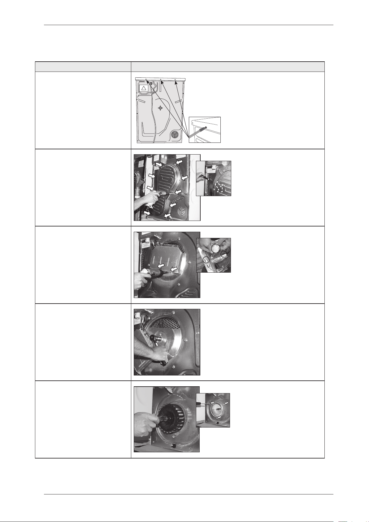
Dismount top cover and back rear
Instructions Illustration
1. Unscrew the top cover.
2. Dismount the panel rear cover by
removing the screws and carefully
bend in the upper edge.
3. Dismount the heating element by
removing the screws and disconnect
the cables.
4. Release the nut bearing lock
(socket wrench 19).
5. Remove the external fan wheel
(socket wrench 10) and unscrew the
encircling screws (Torx 10).
Service Manual TD70.C
34
Service and installation
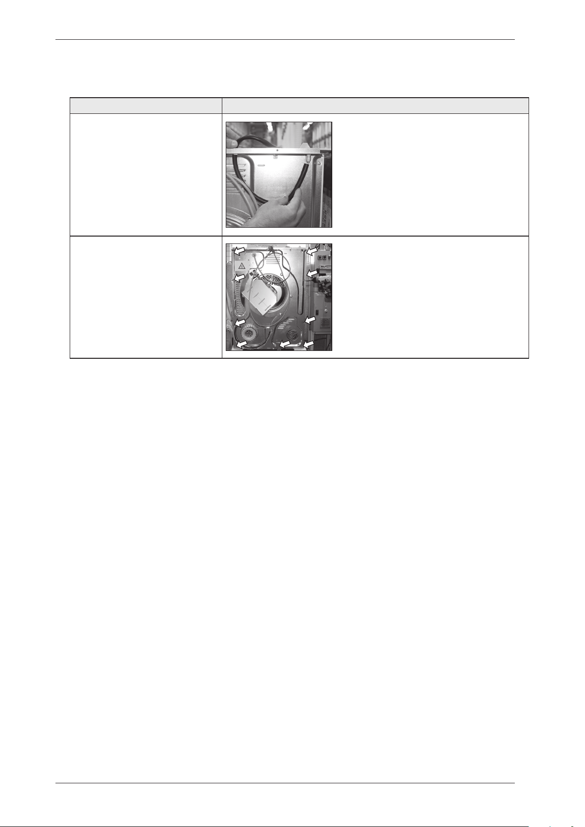
Dismount top cover and back rear cont.
Instructions Illustration
6. Disconnect the rubber hose.
7. Remove the screws on the rear
panel (Torx 20).
Note!
Make sure that the cylinder not fall
down.
A Screw for plastic
B Long screw for plastic
C Screw for plastic
A B C
Service Manual TD70.C
35
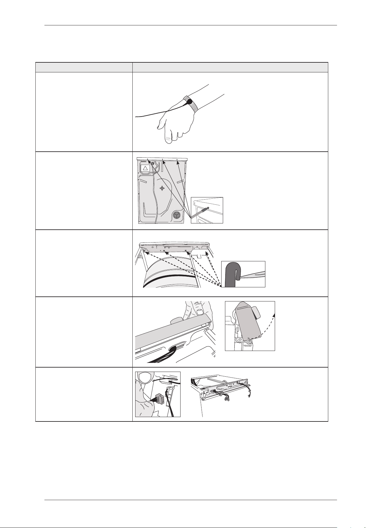
Service and installation
Instructions Illustration
1. Attach the anti-static wristband
to a part of the machine that is
earthed!
NOTE! An anti-static wristband
must be used, otherwise you risk
destroying the control card.
2. Unscrew the top cover.
3. Carefully press the catches
that secure the panel to the front
support. Release the catches from
the front support by working the
panel outwards.
4. Detach the panel by angling and
pulling it carefully outwards at the
lower edge.
Note:Becarefulnottodamagethe
wiring!
5. Carefully disconnect the wiring
from the control unit.
Replacing the panel and the control unit
Service Manual TD70.C
36
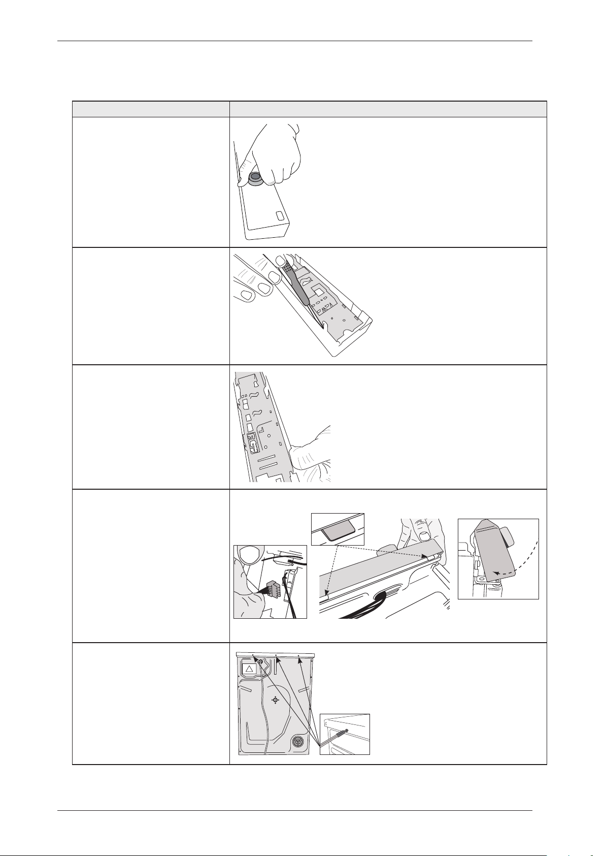
Instructions Illustration
6. Carefully pull the programme
selector from the panel.
7. Use a screwdriver to free the
control card from the panel. NOTE!
The control card must be placed in
an ESD-safe bag.
8. Check that the push button, lens
and decorative inlay are in place.
Now carefully press the new control
card into place.
9.Attachingthepanel:Attach
all wiring to the appropriate
connectors on the control card.
Angle the panel outwards and
place the mounting plates in the
corresponding grooves in the front
frame. Angle the panel downwards
and secure it with the catches
Note:Becarefulnottodamagethe
wiring!
10. Screw the top cover into place.
Service and installation
Replacing the panel and the control unit
Service Manual TD70.C
37
Service and installation
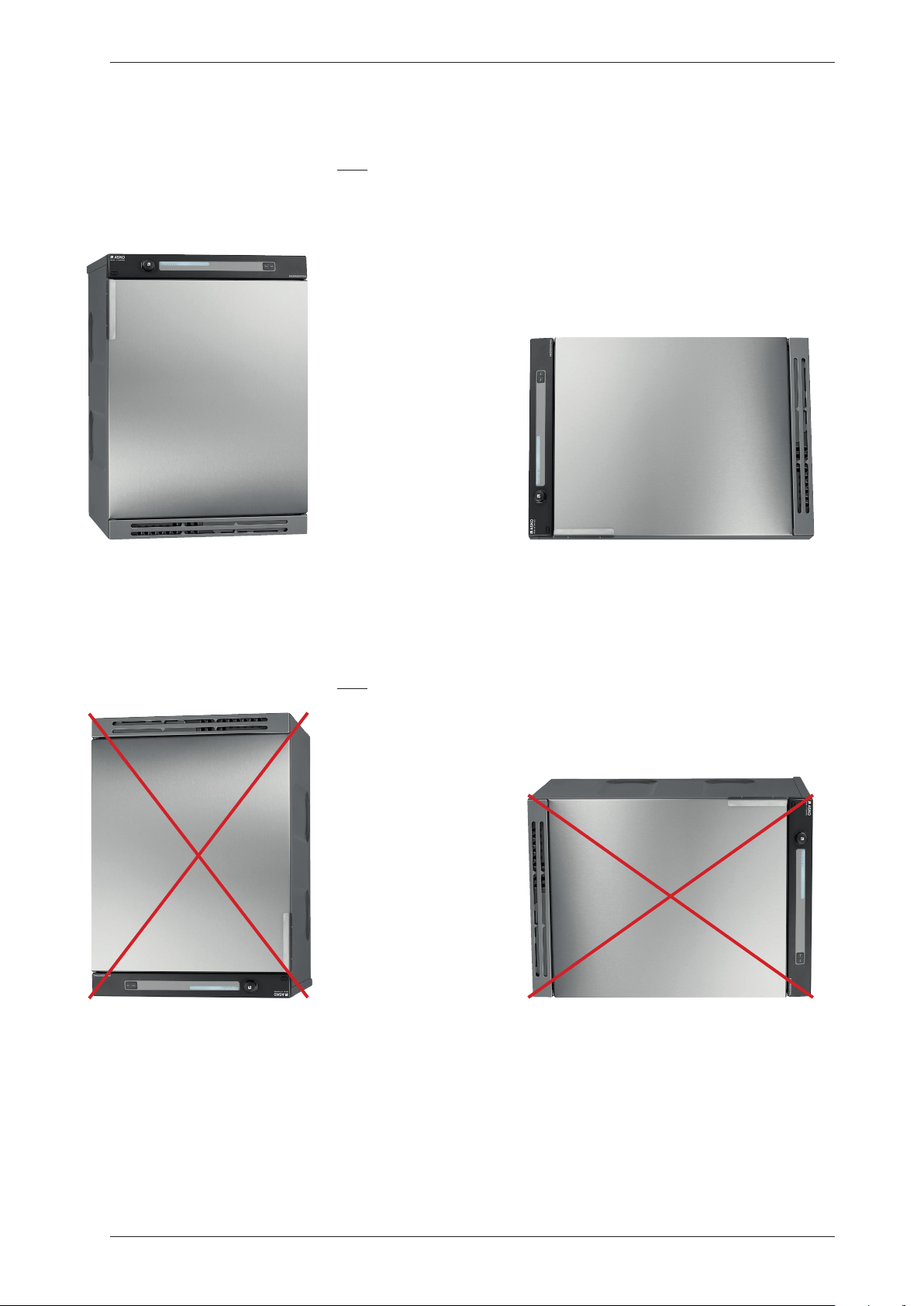
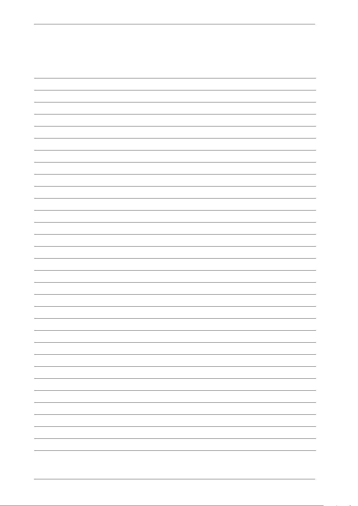
Transporting a tumble dryer with a heat pump
Machines with a heat pump must only be transported upright or placed on the left side when
viewed from the front. In extreme cases, laying the machine on any other side, or transporting it
in an incorrect manner, may result in making the machine unusable. Let the machine stand for 24
hours after transport before use, otherwise the heat pump may be damaged.
OK
OK
NOT OK
NOT OK
Examples of incorrect transport methods
Machines with a heat pump must only be transported as shown above.
Let the machine stand for 24 hours after transport before use, otherwise the heat pump may
be damaged.
Service Manual TD70.C
38
Personal notes
Service Manual TD70.C
39

We reserve the right to make changes.
www.asko.com
80 925 40 Rev08 2012-09-17