
Safety • Assembly • Operation • Adjustment • Maintenance • Troubleshooting • Warranty
A O AL
ii ii
_i_i_i_ii _ iiii
ii_i_i!i_!ii!II_
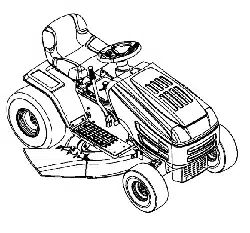
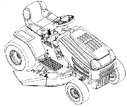
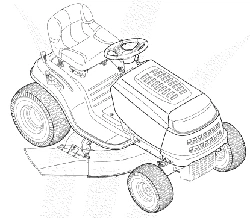
Transmatic Lawn Tractor- Models 760=779
iMPORTANT
READ SAFETY RULES AND iNSTRUCTiONS CAREFULLY BEFORE OPERATION
Warning: Thisunit is equippedwithaninternalcombustionengineandshouldnot beusedon or nearany unimprovedforest-covered,brush-
coveredor grass-coveredlandunlesstheengine'sexhaustsystemis equippedwitha sparkarrestermeetingapplicablelocalor statelaws(if any).
If a sparkarresteris used,it shouldbemaintainedineffectiveworkingorderby the operator.In theStateof Californiathe aboveis requiredbylaw
(Section4442of the CaliforniaPublicResourcesCode). Otherstatesmay havesimilarlaws.Federallawsapplyon federallands.A sparkarrester
for the muffleris availablethroughyour nearestengineauthorizedservicedealeror contactthe servicedepartment,RO.Box361131Cleveland,
Ohio44136-0019.
PRINTEDIN U.S.A.
MTD LLC, P.O. BOX 361131 CLEVELAND, OHIO 44136-0019
FORMNO.769-01598B
01/06/2006

This Operator's Manual is an important part of your new lawn tractor, it will help you assemble,
prepare and maintain the unit for best performance. Please read and understand what it says.
Table of Contents
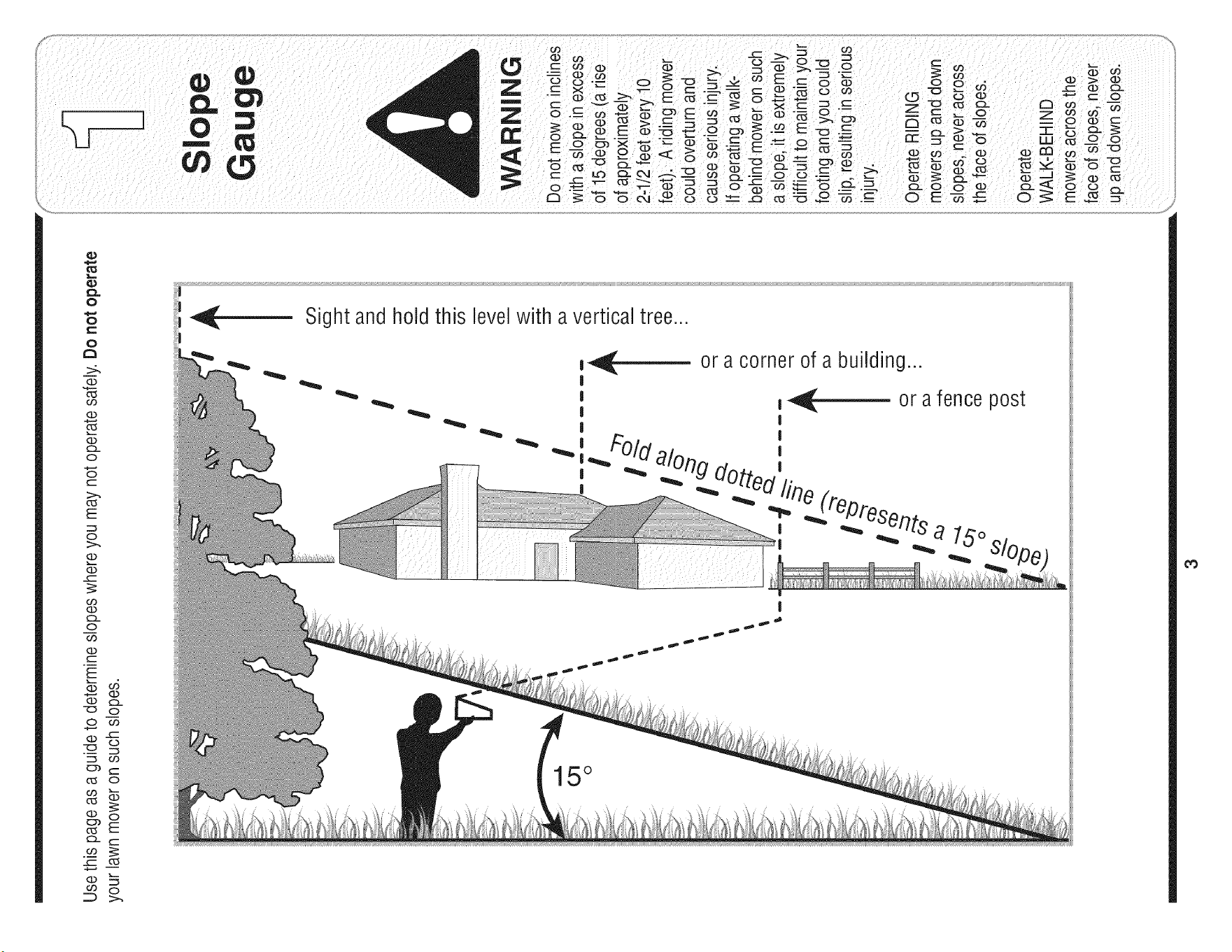
Slope Gauge ....................................................... 3
Safe Operation Practices ................................... 4
Setting UpYour Lawn Tractor ............................ 8
Operating Your Lawn Tractor ........................... 12
Adjusting Your Lawn Tractor ............................ 20
Maintaining Your Lawn Tractor ........................ 22
Off-Season Storage / Attachments ................. 28
Safety Labels .................................................... 29
Trouble Shooting .............................................. 30
Warranty .............................................. Back Page
Finding and Recording Model Number
BEFOREYOU START ASSEMBLING
YOUR NEW EQUIPMENT,
please locatethe model plate on the equipment and copy the
information to the sample model plate provided to the right.
You can locate the model plate by looking beneathe the seat.
This information will be necessary to use the manufacturer's
web site and/or obtain assistance from the Customer Support
Department or an authorized service dealer.
Model Number
www.mtdproducts.com
Serial Number
MTD LLC
P.O= BOX 361131
CLEVELAND, OH 44136
330-220-4683
800-800-7310
Customer Support
Please do NOTretum the unit to the retailer from which it was
purchased, without first contacting Customer Support.
If you have difficulty assembling this product or have any questions regardingthe controls, operation,or maintenanceof this
unit, you can seek help from the experts. Choose from the options below:
1. Visit mtdproducts.com. Click on the Service & Support menu option.
2. Phone a Customer Support Representative at 1 (800) 800-7310.
3. The engine manufacturer is responsiblefor all engine-relatedissues with regardsto performance, power-rating,specifica-
tions, warranty and service. Please refer to the engine manufacturer'sOwner's/Operator's Manual, packed separatelywith
your unit, for more information.
MTD/n_er_@_i®a_ Award Wi_n i_g ?rd_s_ts O_r Com?_ay
Product Menu
o_r_,qo_ _ Suppo_±
Product. Registration
?riv®cy Pd_y
2
O
o
1=
o
>:.
(13
O3
(13
(13
O-
O
O
(--
O5
E
O
(13
(13
o3
(13
O-
O
o3
(13
E
(]3
(13
o
(13
C5
('5
O3
O5
(13
t"b
(13
O9
o5
(13
O-
O
O3
-5
O3
O
O
E
Sight and hold this levelwith a vertical tree...
also
I
15°
Practices
WARNING
This symbol points
out important safety
instructionswhich, if
notfollowed, could
endangerthe personal
safety and/or property
ofyourself and others.
Readand follow all
I instructions in this man-
ual before attempting to
operatethis machine.
tFailureto comply with
hese instructions may
result in personal injury.
When you see this
symbol.
HEED iTS WARNING
Your
Responsibility
Restrictthe use
of this power machine
to persons who read,
understand
and follow the warnings
and instructions
in this manual
WARNING: Engine Exhaust,some of its constituents, and certain vehicle compo-
nents contain or emit chemicals knownto State of Californiato cause cancer and
birth defects or other reproductiveharm.
DANGER: This machinewas built to be operated according to the rules for safe operation in this
manual. As with any type of power equipment, carelessness or error on the part of the operator can
result in serious injury. This machine is capable of amputating hands and feet and throwing objects.
Failureto observe the following safety instructions could result in serious injury or death.
Children
1. Tragicaccidentscanoccurif the operatoris not
alertto the presenceof children.Childrenareoften
attractedto themachineandthe mowingactivity.
Theydo not understandthe dangers.Neverassume
thatchildrenwill remainwhereyou last sawthem.
a. Keepchildrenout of the mowingarea and in
watchfulcare of a responsibleadultother than
the operator.
b. Bealert andturnmachineoff ifa childenters
the area.
c. Beforeandwhile backing,lookbehindand
downfor smallchildren.
d. Nevercarrychildren,evenwiththe blade(s)
shutoff.Theymayfalloffandbeseriously
injuredor interferewithsafemachineoperation.
e. Useextremecarewhenapproachingblind
corners,doorways,shrubs,treesorother
objectsthat mayblockyourvision of a child
whomayrunintothe machine.
f. To avoid back-over accidents, always
disengagethe cuttingblade(s) before
shiftinginto Reverse.if equipped,the
"Reverse CautionMode"shouldnotbe
used whenchildrenor others are around.
g. Keepchildrenaway from hotor running
engines.Theycan sufferburnsfroma hot
muffler.
h. Removekeywhenmachineis unattendedto
preventunauthorizedoperation.
2. Neverallowchildrenunder 14 yearsold to operate
the machine.Children14yearsoldandovershould
readand understandthe operationinstructionsand
safetyrulesinthis manualandshouldbetrainedand
supervisedbya parent.
Operation
Safe Handling of Gasoline:
1. Toavoid personalinjuryor propertydamageuse
extremecare in handlinggasoline.Gasolineis
extremely flammableand the vapors are explo-
sive. Seriouspersonalinjurycan occurwhengasoline
isspilledon yourselfor yourclotheswhichcan ignite.
Washyourskinandchangeclothesimmediately.
a. Useonlyanapprovedgasolinecontainer.
b. Neverfill containersinsidea vehicleor on a
truckor trailerbedwitha plasticliner.Always
placecontainerson the groundawayfrom
yourvehiclebeforefilling.
c. Whenpractical,removegas-powered
equipmentfromthe truckor trailerand refuelit
onthe ground.Ifthis isnotpossible,then
refuelsuchequipmenton a trailerwitha
portablecontainer,ratherthan froma gasoline
dispensernozzle.
d. Keepthe nozzlein contactwith the rimof
the fueltankor containeropeningat all
timesuntilfuelingiscomplete.Donot usea
nozzlelock-opendevice.
e. Extinguishall cigarettes,cigars,pipesand
othersourcesof ignition.
f. Neverfuel machineindoors.
g. Neverremovegas cap oraddfuel whilethe
engineishot or running.Allowengineto cool
at leasttwominutesbeforerefueling.
h. Neveroverfill fuel tank.Fill tank to no more
than1/2inchbelowbottomof filler neck to
allowspacefor fuel expansion.
i. Replacegasolinecapand tighten securely.
j. If gasolineis spilled,wipe it off theengine
andequipment.Moveunit to anotherarea.
Wait5 minutesbeforestartingtheengine.
k. Toreducefirehazards,keepmachinefreeof
grass,leaves,orotherdebris build-up.Clean
upoil or fuel spillageand removeanyfuel
soakeddebris.
I. Neverstorethe machineor fuel container
insidewherethere is anopen flame,spark
orpilot lightas on a waterheater,space
heater,furnace,clothesdryerorother gas
appliances.
m. Allowa machineto cool at leastfive minutes
beforestoring.
4

GeneralOperation:
1. Read,understand,andfollowall instructionsonthe
machineandin the manual(s)beforeattemptingto
assembleand operate.Keepthis manualin a safe
placefor futureandregularreferenceandfor ordering
replacementparts.
2. Be familiarwith allcontrolsandtheir properoperation.
Knowhow to stopthe machineand disengagethem
quickly.
3, Neverallowchildrenunder14yearsold to operate
this machine.Children14years old and overshould
readandunderstandthe operationinstructionsand
safetyrulesinthis manualandshouldbetrainedand
supervisedby a parent.
4. Neverallowadultsto operatethis machinewithout
properinstruction.
5. To helpavoidbladecontactora thrownobject injury,
keep bystanders,helpers,childrenand petsat least
75feet fromthe machinewhileit is in operation.Stop
machineif anyoneenters thearea.
6. Thoroughlyinspecttheareawheretheequipmentis to
be used. Removeall stones,sticks,wire,bones,toys,
andotherforeignobjectswhichcouldbe pickedup
andthrownbythe blade(s).Thrownobjectscancause
seriouspersonalinjury.
7. Planyourmowingpatternto avoiddischargeof
materialtowardroads,sidewalks,bystandersandthe
like.Also,avoiddischargingmaterialagainstawall or
obstructionwhichmaycausedischargedmaterialto
ricochetback towardthe operator.
8. Alwayswear safetyglassesor safetygogglesduring
operationand while performingan adjustmentor
repairto protectyoureyes.Thrownobjectswhich
ricochetcancauseseriousinjuryto the eyes.
9. Wearsturdy,rough-soledworkshoesandclose-fitting
slacksandshirts.Loosefittingclothesandjewelry
can becaughtinmovableparts.Neveroperatethis
machinein barefeet or sandals.
10.Be awareof the mowerandattachmentdischarge
directionanddo not pointit at anyone.Donot operate
the mowerwithoutthe dischargecoveror entiregrass
catcherin its properplace.
11.Donot put handsor feetnear rotatingpartsor under
the cuttingdeck. Contactwiththe blade(s)can
amputatehandsand feet.
12.A missingor damageddischargecovercan cause
bladecontactorthrownobjectinjuries.
13.Stop the blade(s)whencrossinggraveldrives,walks,
or roadsand whilenot cuttinggrass.
14.Watchfor trafficwhenoperatingnearor crossing
roadways.This machineis not intendedfor useon
anypublic roadway.
15.Do notoperatethe machinewhileunderthe influ-
enceof alcoholor drugs.
16.Mowonly in daylightor goodartificiallight.
17.Nevercarry passengers.
18.Disengageblade(s)beforeshiftinginto reverse.
Backupslowly.Alwayslookdownandbehindbefore
andwhilebackingto avoida back-overaccident.
19.Slowdownbeforeturning.Operatethe machine
smoothly.Avoiderraticoperationand excessive
speed.
20.Disengageblade(s),set parkingbrake,stopengine
andwaituntilthe blade(s)cometo a completestop
beforeremovinggrass catcher,emptyinggrass,
uncloggingchute,removingany grassor debris,or
makinganyadjustments.
21.Neverleavea runningmachineunattended.Always
turnoff blade(s), placetransmissionin neutral,set
parkingbrake,stopengineand removekey before
dismounting.
22.Useextracare whenloadingorunloadingthe
machineintoa traileror truck. This unit shouldnot
bedrivenupor downramp(s),becausethe unit
couldtip over,causingseriouspersonalinjury.The
unit mustbepushedmanuallyon ramp(s)to load or
unloadproperly.
23.Mufflerandenginebecomehotandcan causea
burn.Do nottouch.
24.Checkoverheadclearancescarefullybeforedriving
underlowhangingtreebranches,wires,dooropen-
ingsetc.,wheretheoperatormaybe struckor pulled
fromthe unit,whichcouldresultinseriousinjury.
25.Disengageall attachmentclutches,depressthe
brakepedalcompletelyandshift into neutralbefore
attemptingto startengine.
26.Yourmachineisdesignedto cutnormalresidential
grassof a heightno morethan 10".Do notattemptto
mowthroughunusuallytall,dry grass(e.g.,pasture)
or pilesof dry leaves.Drygrassor leavesmay
contactthe engineexhaustand/orbuild up on the
mowerdeckpresentinga potentialfire hazard.
27.Use onlyaccessoriesandattachmentsapprovedfor
thismachinebythe machinemanufacturer.Read,
understandandfollowall instructionsprovidedwith
the approvedaccessoryor attachment.
28.Data indicatesthat operators,age 60 yearsand
above,are involvedin a largepercentageof riding
mower-relatedinjuries.Theseoperatorsshould
evaluatetheirabilityto operatethe ridingmower
safelyenoughto protectthemselvesand othersfrom
seriousinjury.
29.If situationsoccurwhichare not coveredin this
manual,usecareandgoodjudgment.Contactyour
customerservicerepresentativefor assistance.
........................................................................................
WARNING
This symbol points
out important safety
instructions which, if
not followed, could
endanger the personal
safety and/or property
of yourself and others.
Readand follow all
instructions in this man-
ual before attempting to
operate this machine.
Failureto comply with
these instructionsmay
result in personal injury.
When you see this
symbol.
HEED ITS WARNING
Your
Responsibility
Restrictthe use
of this power machine
to persons who read,
understand
and follow the warnings
and instructions
in this manual
5
Thissymbolpoints
outimportantsafety
instructionswhich,if
notfollowed,could
endangerthepersonal
i safetyand/orproperty
ofyourselfandothers.
Readandfollowall
instructionsinthisman-
ualbeforeattemptingto
I operatethismachine.
I Failuretocomplywith
theseinstructionsmay
i resultin personalinjury.
Whenyouseethis
symbol.
i HEED ITSWARNING
Your
i Responsibility
Restrictthe use
of this power machine
to persons who read,
understand
and follow the warnings
and instructions
in this manual
Slope Operation:
Slopesare a majorfactor relatedto loss of controland
tip-overaccidentswhichcan resultin severeinjuryor
death.All slopesrequireextracaution.If youcannot
backupthe slopeor if youfeel uneasyon it, do notmow
it.
Foryour safety,usethe slopegaugeincludedas partof
thismanualto measureslopesbeforeoperatingthisunit
ona slopedor hillyarea. If the slopeis greaterthan 15
degreesas shownon theslopegauge,do notoperate
thisunit onthatareaor seriousinjurycouldresult.
DO:
1. Mowupanddownslopes,notacross. Exercise
extremecautionwhenchangingdirectiononslopes.
2. Watchfor holes, ruts,bumps,rocks,orother hidden
objects.Uneventerraincouldoverturnthe machine.
Tallgrasscan hideobstacles.
3. Useslowspeed.Choosea low enoughspeed
settingso thatyouwill not haveto stopor shift while
onthe slope.Tires may losetractionon slopeseven
thoughthe brakesare functioningproperly.Always
keepmachineingearwhengoingdown slopesto
takeadvantageof engine brakingaction.
4. Followthe manufacturer'srecommendationsfor
wheelweightsorcounterweightsto improvestability.
5. Useextracare with grasscatchersor otherat-
tachments.Thesecanchangethe stabilityof the
machine.
6. Keepall movementon the slopesslowand gradual.
Do not makesuddenchangesin speedor direction.
Rapidengagementor brakingcouldcausethe front
of the machineto liftand rapidlyflip overbackwards
whichcouldcauseseriousinjury.
7. Avoidstartingor stoppingon a slope.If tireslose
traction,disengagethe blade(s)andproceedslowly
straightdownthe slope.
Do Not:
1. Do notturn on slopesunlessnecessary;then,turn
slowlyandgraduallydownhill,if possible.
2. Do not mownear drop-offs,ditchesor embankments.
Themowercouldsuddenlyturnoverif a wheel is over
the edgeof a cliff,ditch,or if an edgecavesin.
3. Do nottry to stabilizethe machineby puttingyourfoot
onthe ground.
4. Do not usea grasscatcheron steep slopes.
5. Do not mowon wet grass. Reducedtractioncould
causesliding.
6. Do not shiftto neutralandcoastdownhill.Over-speed-
ingmaycausethe operatorto losecontrol of the
machineresultingin seriousinjuryor death.
7. Do nottowheavypullbehindattachments(e.g.loaded
dumpcart, lawnroller,etc.)on slopesgreaterthan
5 degrees.Whengoingdown hill,the extra weight
tendsto pushthe tractorand may causeyou to loose
control.(e.g. tractormayspeedup, brakingand steer-
ingabilityarereduced,attachmentmayjack-knifeand
causetractorto overturn).
Towing:
1. Towonlywitha machinethat hasa hitchdesignedfor
towing.Donot attachtowedequipmentexceptat the
hitchpoint.
2. Followthe manufacturersrecommendationfor weight
limitsfor towedequipmentandtowingon slopes.
3. Neverallowchildrenor othersin oron towedequip-
ment.
4. Onslopes,the weightof the towedequipmentmay
causelossof tractionandlossof control.
5. Travelslowlyandallowextradistanceto stop.
6. Do not shiftto neutralandcoastdownhill.
6
Service
1. Neverrunanengineindoorsorina poorlyventilated
area. Engineexhaustcontainscarbonmonoxide,an
odorless,and deadlygas.
2. Beforecleaning,repairing,or inspecting,makecertain
the blade(s)andall movingparts havestopped.
Disconnectthe sparkplug wireandgroundagainstthe
engineto preventunintendedstarting.
3. Periodicallycheckto make surethe bladescometo
completestop withinapproximately(5) five seconds
afteroperatingthe bladedisengagementcontrol.If the
bladesdo notstop within thethis timeframe,yourunit
shouldbe servicedprofessionallyby an authorized
MTDServiceDealer.
4. Checkbrakeoperationfrequentlyas it is subjectedto
wearduringnormaloperation.Adjustand serviceas
required.
5. Checkthe blade(s)andenginemountingboltsat
frequentintervalsfor propertightness.Also,visually
inspectblade(s)for damage(e.g.,excessivewear,
bent,cracked). Replacethe blade(s)withtheoriginal
equipmentmanufacturer's(O.E.M.)blade(s)only,
listedinthis manual."Useof partswhich do not meet
the originalequipmentspecificationsmaylead to
improperperformanceandcompromisesafety!"
6. Mowerbladesaresharp.Wrapthe bladeor wear
gloves,anduseextracautionwhenservicingthem.
7. Keepall nuts, bolts,andscrewstightto be surethe
equipmentis insafeworkingcondition.
8. Nevertamperwith the safety interlocksystemor other
safetydevices.Checktheir properoperationregularly.
9. Afterstrikingaforeignobject,stop the engine,
disconnectthe spark plug wire(s)and groundagainst
the engine.Thoroughlyinspectthe machinefor any
damage.Repairthe damagebeforestartingand
operating.
10.Neverattemptto makeadjustmentsor repairsto the
machinewhilethe engineisrunning.
11.Grasscatchercomponentsand the discharge
coveraresubjectto wearanddamagewhichcould
exposemovingpartsor allowobjectsto be thrown.
Forsafetyprotection,frequentlycheckcomponents
andreplaceimmediatelywith originalequipment
manufacturer's(O.E.M.)partsonly,listed in this
manual."Useof partswhichdo not meetthe original
equipmentspecificationsmay leadto improper
performanceandcompromisesafety!"
12.Do notchangethe enginegovernorsettingsor
over-speedthe engine.Thegovernorcontrolsthe
maximumsafeoperatingspeedof the engine.
13.Maintainor replacesafetyandinstructionlabels,as
necessary.
14.Observeproperdisposallawsand regulationsfor
gas,oil,etc. to protecttheenvironment.
7
This symbol points
out important safety
instructions which, if
not followed, could
endangerthe personal
safety and/or property
of yourselfand others.
Read and follow all
instructions in this man-
ual before attempting to
operatethis machine.
Failureto comply with
these instructions may
result in personal injury.
When you see this
symbol.
HEED iTS WARNING
Your
Responsibility
Restrictthe use
of this power machine
to personswho read.
understand
and follow the warnings
and instructions
in this manual
Tractor
Use extreme care
whenhandling
gaso nelGasoline
extremely flammable
and the vapors are
explosive: Never fuel
machine indoors
or while the engine
is hot or running,
Extinguish cigarettes,
cigars, pipes, and
othersourcesof
ignitionl
NOTE: This Operators
Manual Coversa range
of produCtspecifications
for VariousmodelS:
Characteristics and
i
featuresdiscussed
and/or illustratedin
s manualmay not
applicable toall models:
MTD LLC reservesthe
right to change product
specifications, (Jesigns
and equipment without
notice and without incur-
i[ing obligatiOnl
RubberBoot
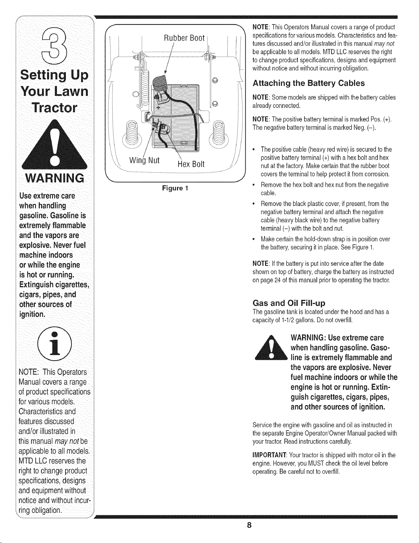
Figure 1
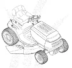
NOTE:ThisOperatorsManualcoversa rangeof product
specificationsfor variousmodels.Characteristicsandfea-
turesdiscussedand/orillustratedin this manualmay not
beapplicableto all models.MTDLLCreservesthe right
to changeproductspecifications,designsandequipment
withoutnotice and withoutincurringobligation.
Attaching the Battery Cables
NOTE:Somemodelsare shippedwiththe batterycables
alreadyconnected.
NOTE:Thepositivebatteryterminalis markedPos. (+).
Thenegativebatteryterminalis markedNeg.(-).
• Thepositivecable(heavyredwire) is securedto the
positivebatteryterminal(+)witha hexbolt and hex
nut at thefactory.Makecertainthatthe rubberboot
coversthe terminalto help protectit fromcorrosion.
• Removethehex boltand hexnut fromthe negative
cable.
• Removetheblack plasticcover,if present,from the
negativebatteryterminalandattachthe negative
cable(heavyblackwire)to the negativebattery
terminal(-) withthe bolt and nut.
• Makecertainthehold-downstrapis in positionover
the battery,securingit in place.See Figure1.
NOTE:Ifthe batteryis putinto serviceafterthe date
shownontop of battery,chargethe batteryas instructed
onpage24of this manualprior to operatingthe tractor.
Gas and Oil Fill-up
Thegasolinetank is locatedunderthe hoodandhasa
capacityof 1-1/2gallons.Donot overfill.
WARNING: Use extreme care
when handling gasoline. Gaso-
line is extremely flammable and
the vapors are explosive. Never
fuel machine indoors or while the
engine is hot or running. Extin-
guish cigarettes, cigars, pipes,
and other sources of ignition.
Servicethe enginewith gasolineandoil as instructedin
the separateEngineOperator/OwnerManualpackedwith
yourtractor.Readinstructionscarefully.
IMPORTANT:Yourtractoris shippedwith motoroil in the
engine.However,you MUSTcheckthe oil levelbefore
operating.Becarefulnotto overfill.
8
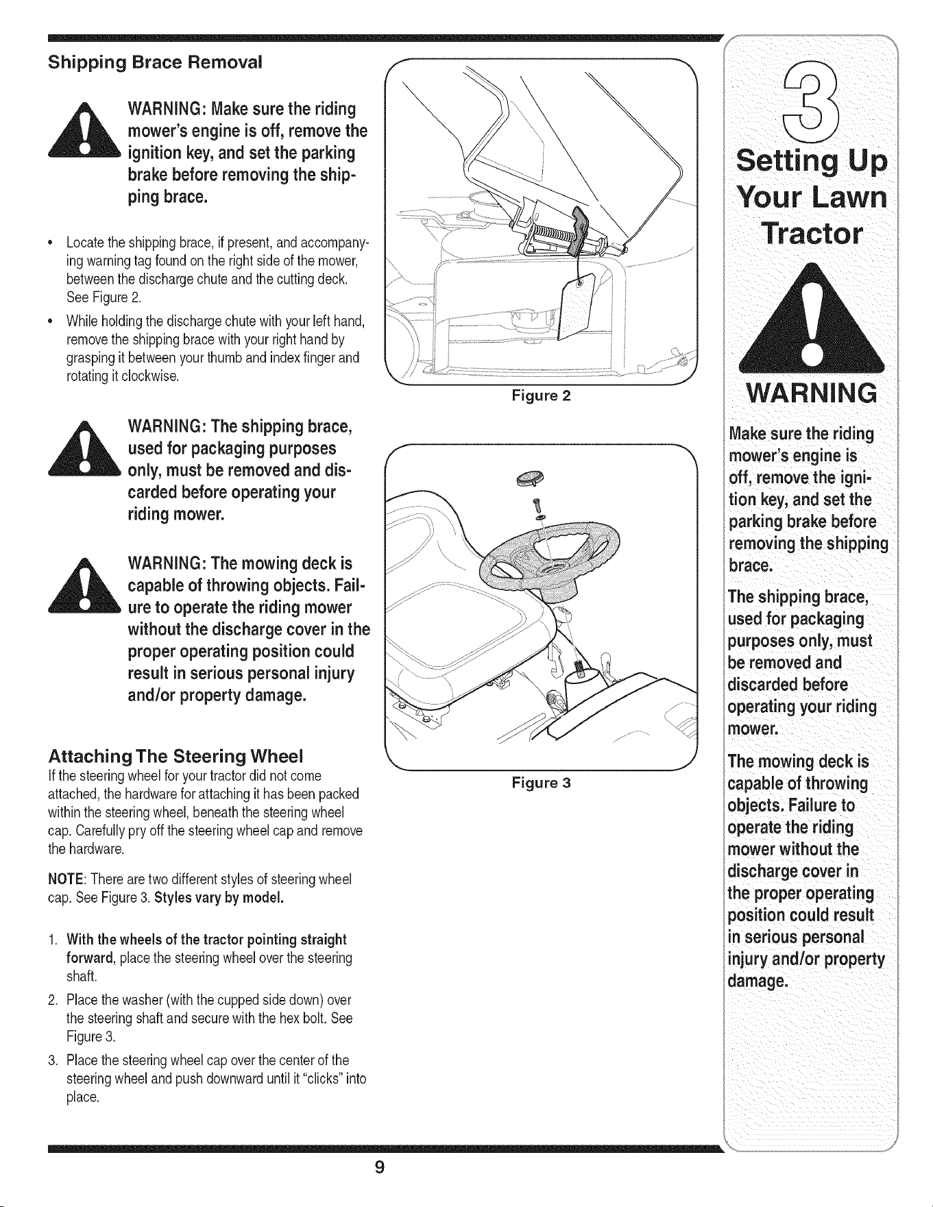
Shipping Brace Removal f
WARNING: Make sure the riding
mower's engine is off, remove the
ignition key, and set the parking
brake before removing the ship-
ping brace.
• Locatethe shippingbrace,ifpresent,andaccompany-
ingwarningtag foundon the rightside of the mower,
betweenthe dischargechuteand thecuttingdeck.
See Figure2.
• Whileholdingthe dischargechute with yourleft hand,
removethe shippingbracewith your righthandby
graspingitbetweenyour thumbandindexfingerand
rotatingitclockwise.
WARNING: The shipping brace,
used for packaging purposes
only, must be removed and dis-
carded before operating your
riding mower.
WARNING: The mowing deck is
capable of throwing objects. Fail-
ure to operate the riding mower
without the discharge cover in the
proper operating position could
result inserious personal injury
and/or property damage.
Attaching The Steering Wheel
Ifthe steeringwheelforyour tractordid notcome
attached,the hardwarefor attachingit hasbeenpacked
withinthe steeringwheel,beneaththe steeringwheel
cap.Carefullypry off the steeringwheelcapand remove
the hardware.
NOTE:Thereare two differentstylesof steeringwheel
cap.SeeFigure3. Styles vary by model.
1. With the wheels of the tractor pointingstraight
forward, placethe steeringwheeloverthe steering
shaft.
2. Placethe washer(withthecuppedsidedown)over
the steeringshaftandsecurewiththe hex bolt.See
Figure3.
3. Placethe steeringwheelcap overthe centerof the
steeringwheelandpushdownwarduntilit"clicks"into
place.
Figure 2
Figure 3
TractOr
WARNING
Make sure the riding
mower's engine is
off, remove the igni-
tion key, and set the
parking brake before
removingthe shipping
brace.
The shipping brace,
used for packaging
purposes only, must
be removed and
discarded before
operating your riding
mower.
The mowing deck is
capable of throwing
objects. Failureto
operate the riding
mower without the
discharge cover in
the proper operating
position could result
in serious personal
injury and/or property
damage.
9
WARNING
Before operatingthis
machine,makesure
the seat is engaged in
the seat stop; stand
behindthemachine
andpu,backonseat
fu,yengaged
intostop:
NOTE: Forsh pping rea:
s0nsl Seatsareeither
fastenedto the tractor
seat's pivot braCketWitt
a plastiCtie, or mounted
backward to the pivot
bracket. In either case;
free the seat form its
shipping p0sition and
remove the two Box
screws (or knobsion
models so equipped)
from thebottom of seat
before proceedingwith
applicable instructions:
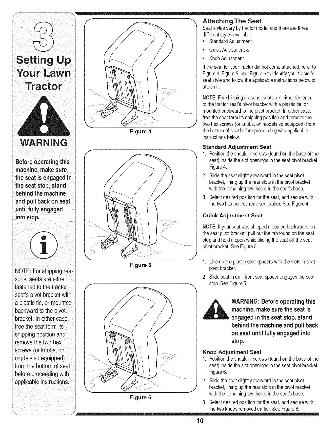
Attaching The Seat
Seatstylesvarybytractormodeland thereare three
differentstyles available:
• StandardAdjustment
• QuickAdjustment&
• KnobAdjustment
If the seatfor yourtractordid notcomeattached,referto
Figure4, Figure5, and Figure6 to identifyyourtractor's
seatstyleandfollowthe applicableinstructionsbelowto
attachit.
Figure 4
NOTE:Forshippingreasons,seatsare eitherfastened
to the tractorseat'spivotbracketwitha plastictie,or
mountedbackwardto the pivot bracket.Ineithercase,
freethe seatformitsshippingpositionand removethe
twohex screws(or knobs,on modelsso equipped)from
the bottomof seatbeforeproceedingwith applicable
instructionsbelow.
Standard Adjustment Seat
1. Positionthe shoulderscrews(foundonthe baseof the
seat)insidetheslot openingsin the seat pivot bracket.
Figure4.
2. Slidethe seatslightlyrearwardin the seat pivot
bracket,liningupthe rearslots in the pivot bracket
withthe remainingtwo holesin the seat'sbase.
3. Selectdesiredpositionforthe seat,andsecurewith
the two hex screwsremovedearlier.See Figure4.
Quick Adjustment Seat
NOTE:Ifyour seatwasshippedmountedbackwardson
the seat pivotbracket,pull outthe tab foundonthe seat
stopandholdit openwhileslidingthe seatoff the seat
pivotbracket.SeeFigure5.
Figure 5
1. Lineupthe plasticseatspacerswith the slotsin seat
pivotbracket.
2. Slideseatinuntilfrontseatspacerengagesthe seat
stop.SeeFigure5.
WARNING" Before operating this
machine, make sure the seat is
engaged inthe seat stop, stand
behind the machine and pull back
on seat until fully engaged into
stop.
Figure 6
Knob Adjustment Seat
1. Positionthe shoulderscrews(foundonthe baseof the
seat)insidetheslot openingsin the seat pivot bracket.
Figure6.
2. Slidethe seatslightlyrearwardin the seat pivot
bracket,liningupthe rearslots in the pivot bracket
withthe remainingtwo holesin the seat'sbase.
3. Selectdesiredpositionforthe seat,andsecurewith
the two knobsremovedearlier.See Figure6.
10
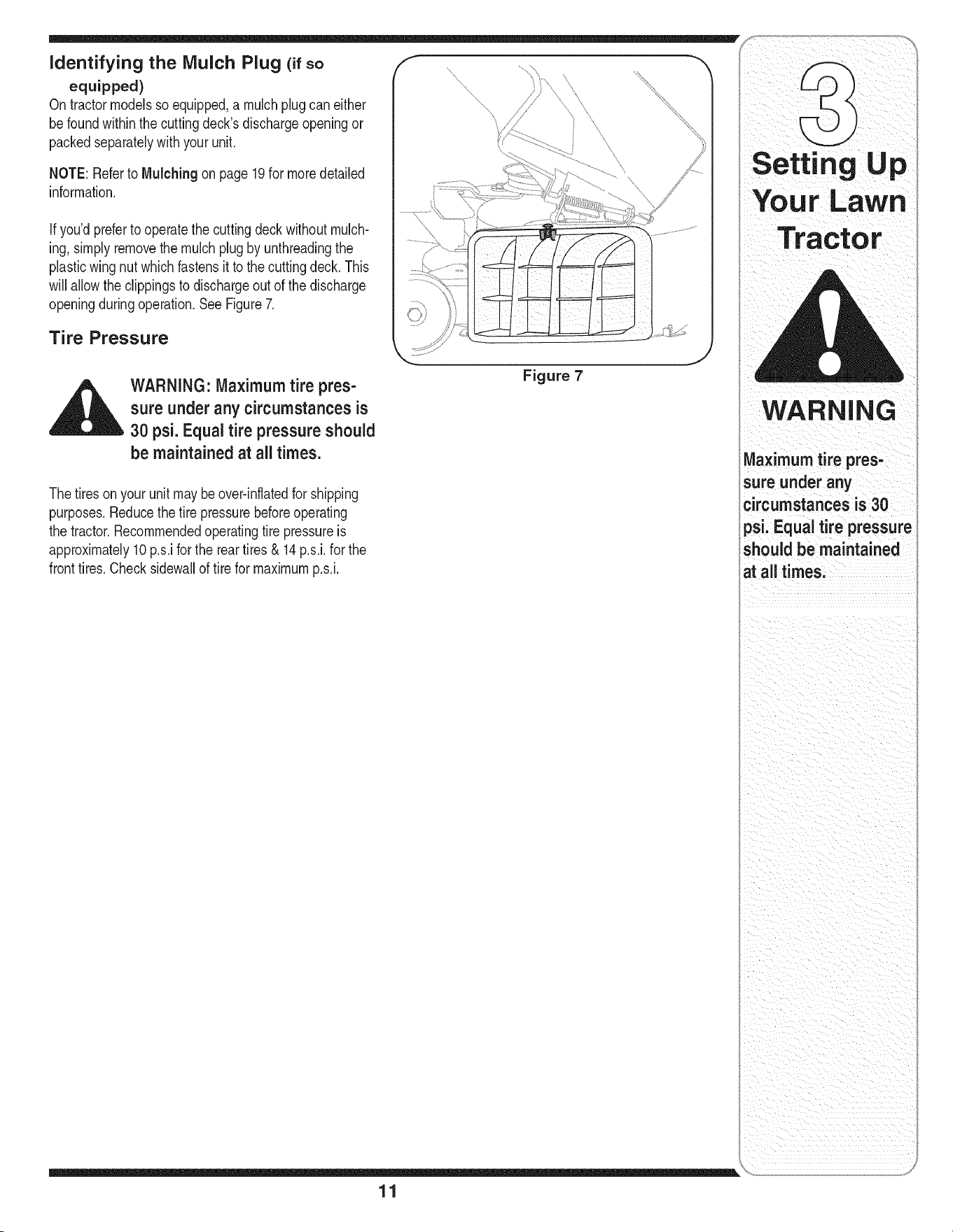
identifying the Mulch Plug (if so /,f
equipped)
|
On tractormodelssoequipped,a mulchplug can either
be foundwithinthe cuttingdeck'sdischargeopeningor
packedseparatelywithyour unit.
NOTE: Referto Mulching on page19for moredetailed
information.
Ifyou'dpreferto operatethe cuttingdeckwithoutmulch-
ing, simplyremovethe mulchplugby unthreadingthe
plasticwing nutwhich fastensit to the cuttingdeck.This
will allowthe clippingsto dischargeout of the discharge
openingduringoperation.SeeFigure7.
Tire Pressure
,_ WARNING: Maximum tire pres-
sure under any circumstances is
30 psi. Equal tire pressure should
be maintained at all times.
Figure 7
The tiresonyour unitmaybeover-inflatedfor shipping
purposes.Reducethetire pressurebeforeoperating
the tractor.Recommendedoperatingtire pressureis
approximately10 p.s.ifor the rear tires & 14p.s.i,for the
fronttires.Checksidewallof tirefor maximump.s.i.
11
WARNING
Maximumtirepres,
sure under any
circumstances is 30
psi, Equal tire pressure
should be maintained
at all times,
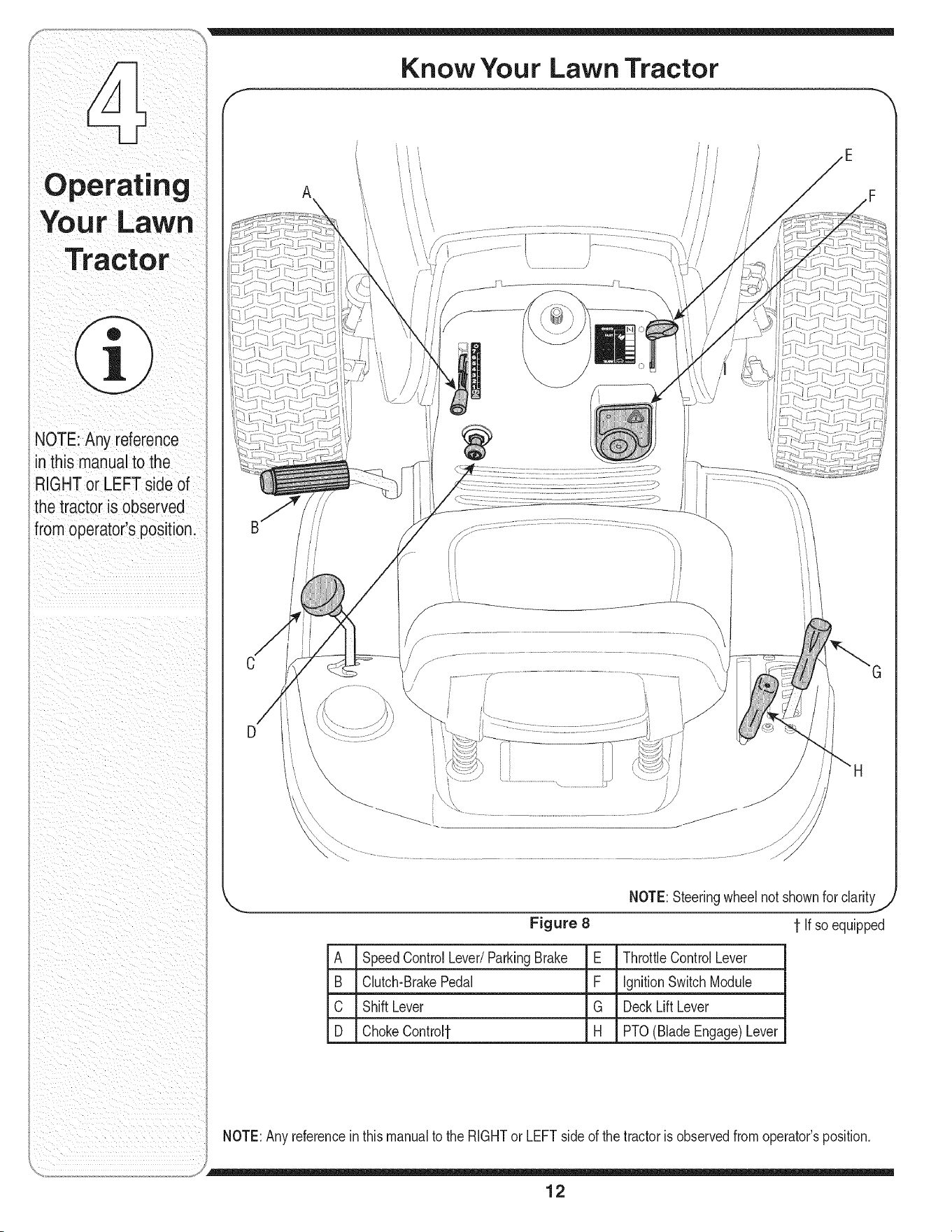
Know Your Lawn Tractor
NOTE: Any reference
in this manual to the
RIGHTor LEFT side of
the tractor is observed
from operator's position.
A
Figure 8
NOTE:Steeringwheelnot shownfor clarity
1-If soequipped
A SpeedControlLever/ParkingBrake E ThrottleControlLever
B Clutch-BrakePedal F IgnitionSwitchModule
C ShiftLever G DeckLift Lever
D ChokeControl1- H PTO(BladeEngage)Lever
NOTE:Anyreferencein this manualto the RIGHTor LEFTside of the tractoris observedfromoperator'sposition.
12
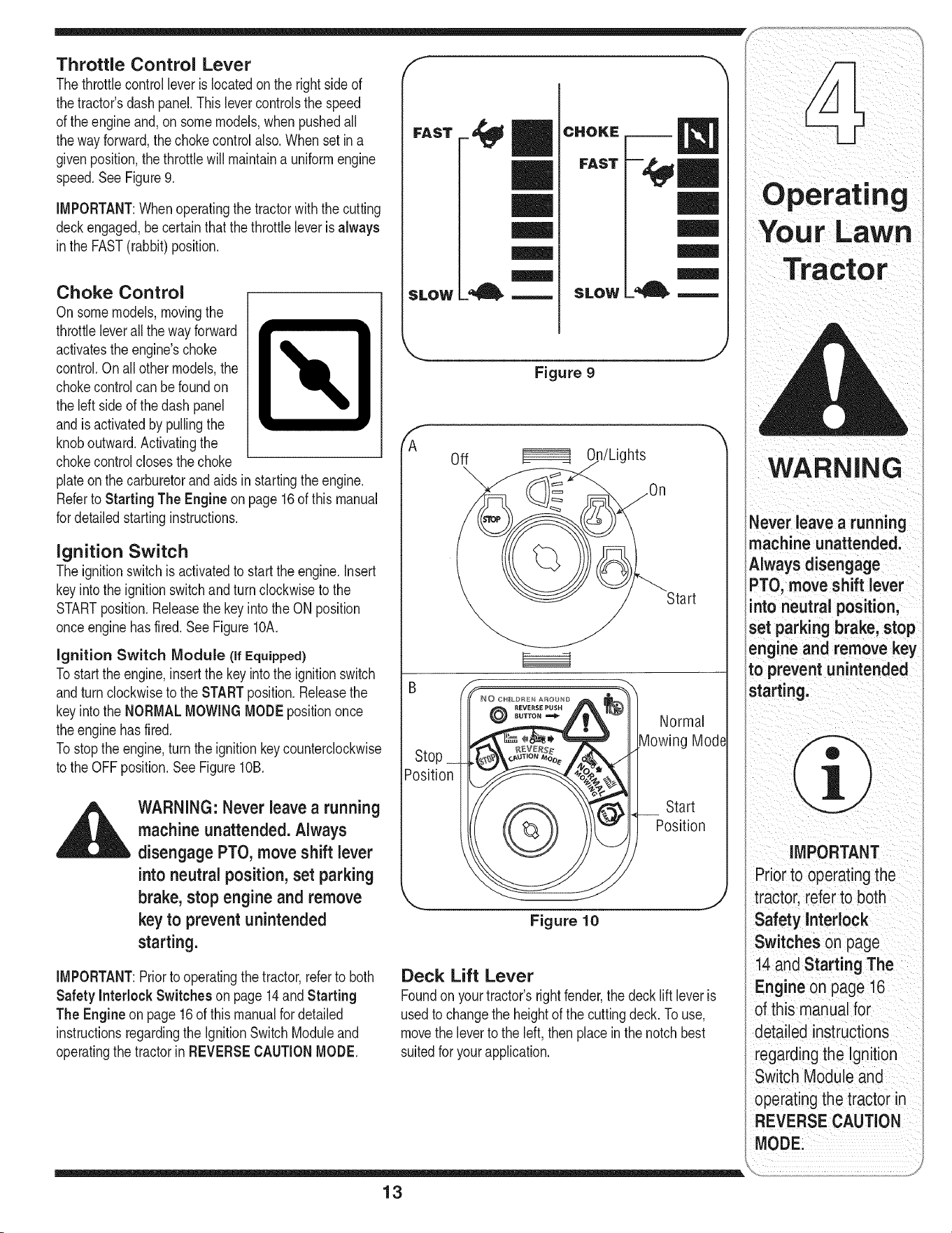
Throttle Control Lever
Thethrottlecontrolleveris locatedon the rightside of
thetractor'sdash panel.Thislevercontrolsthe speed
of the engineand,on somemodels,when pushedall
thewayforward,the chokecontrol also.Whenset ina
givenposition,the throttlewill maintaina uniformengine
speed.SeeFigure9.
IMPORTANT:Whenoperatingthetractorwiththe cutting
deckengaged,be certainthat the throttleleverisalways
inthe FAST(rabbit)position.
Choke Control
Onsomemodels,movingthe
throttleleverall the way forward
activatestheengine'schoke _L._
control.On all othermodels,the
chokecontrolcan be foundon
the left side of thedash panel
andisactivatedby pullingthe
knoboutward.Activatingthe
chokecontrolclosesthe choke
plateonthe carburetorandaids instartingthe engine.
Referto Starting The Engineon page 16of this manual
for detailedstartinginstructions.
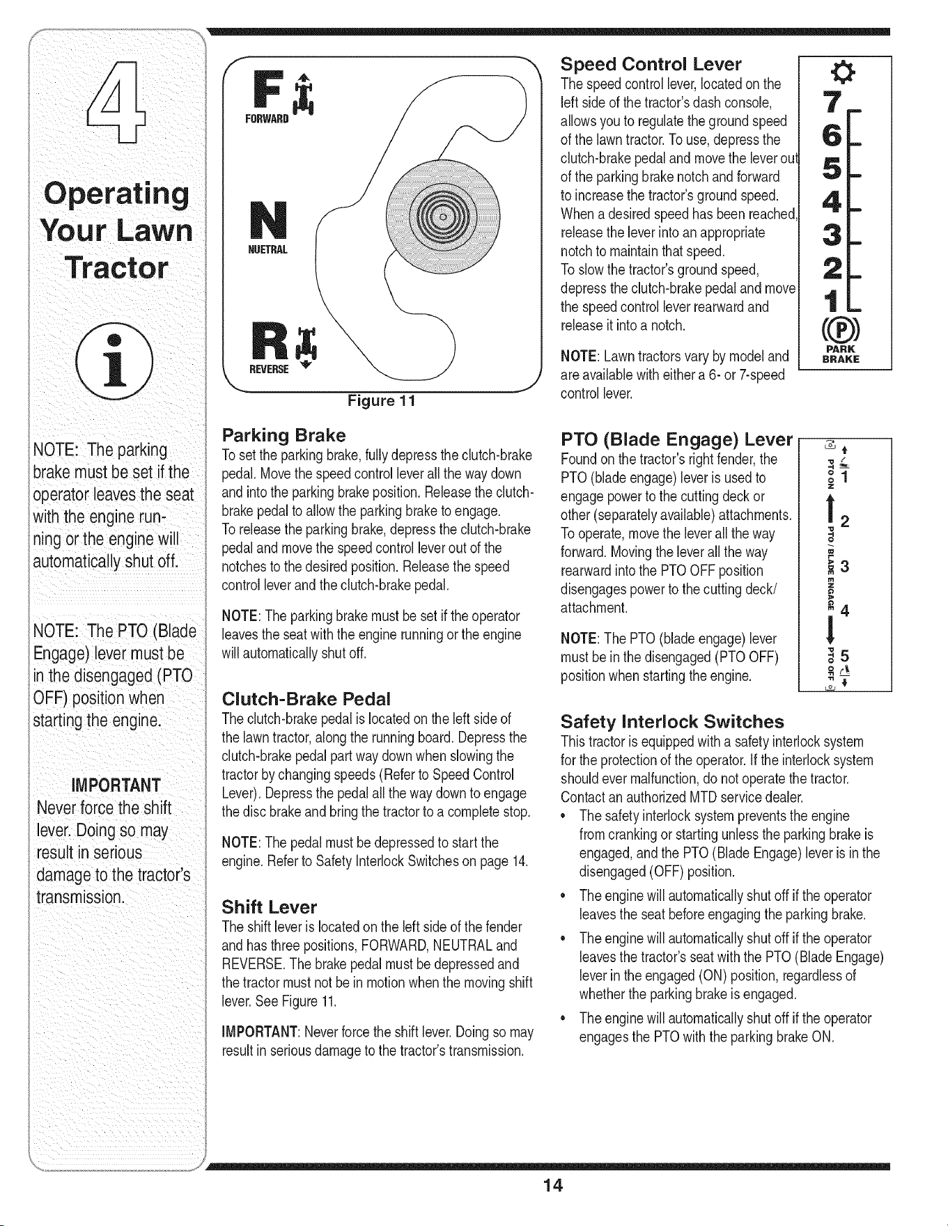
Ignition Switch
The ignitionswitchisactivatedto startthe engine.Insert
keyintothe ignitionswitchandturnclockwiseto the
STARTposition.Releasethe keyintothe ON position
onceenginehasfired.SeeFigure10A.
ignition Switch Module (if Equipped)
Tostart theengine,insertthe key intothe ignitionswitch
andturnclockwiseto the STARTposition.Releasethe
keyintothe NORMALMOWINGMODEpositiononce
theenginehasfired.
Tostopthe engine,turn theignitionkey counterclockwise
to the OFFposition.See FigurelOB.
WARNING: Never leave a running
machine unattended, Always
disengage PTO, move shift lever
into neutral position, set parking
brake, stop engine and remove
key to prevent unintended
starting,
IMPORTANT:Priorto operatingthetractor,referto both
Safety Interlock Switches on page14and Starting
The Engine on page 16 of this manualfordetailed
instructionsregardingthe IgnitionSwitchModuleand
operatingthe tractorin REVERSECAUTIONMODE.
FAST--4pm
|l
SLOW __ .,-.--.
SLOW
Figure 9
Off
n/Lights
Start
Position
©
Normal
Mode
Start
Position
Figure 10
Deck Lift Lever
Foundon yourtractor'srightfender,the deck lift leveris
usedto changethe heightof the cuttingdeck. Touse,
movethe leverto the left, then placeinthe notchbest
suitedforyour application.
i _ i : iii ii I ii i_/I
WARNING
lever leave a running
machine unattended,
Always disengage
PTO, move shift lever
nto neutral position,
set parking ake, stop
engine and remove key
to preventunintended
startingl
IMPORTANT
Priortooperatingthe
tractor, refer to both
Safety Interlock
Switchesonpag
14and
Engine 0n page i6
ofthismanualior
regardingthe Ignition
Switch Module and
operating the tractor in
REVERIE CAUTION
MODEi
13
NOTE:Theparking
brakemustbesetifthe
operatorleavestheseat
withthe enginerun-
ningortheenginewill
automaticallyshutoff.
NOTE:ThePTO(Blade
Engage)levermustbe
inthedisengaged(PTO
:3FF)positionwhen
startingtheengine.
iMPORTANT
Neverforce the shift
lever.Doing so may
result in senous
damage to the tractor's
transmission.
FORWARD
HUETRAL
REVERSE_
Figure 11
Speed Control Lever
Thespeedcontrollever,locatedonthe
left sideof the tractor'sdash console,
allowsyouto regulatethegroundspeed
of the lawntractor.To use,depressthe
clutch-brakepedal and movethe leveroul
of the parkingbrakenotchandforward
to increasethe tractor'sgroundspeed.
Whenadesiredspeedhasbeen reached
releasethe leverintoan appropriate
notchto maintainthatspeed.
Toslowthe tractor'sgroundspeed,
depresstheclutch-brakepedaland move
the speedcontrolleverrearwardand
releaseit intoa notch.
NOTE:Lawntractorsvary by modeland
areavailablewith eithera 6- or 7-speed
controllever.
Parking Brake
Tosetthe parkingbrake,fullydepressthe clutch-brake
pedal.Movethe speedcontrol leverallthe waydown
andintothe parkingbrakeposition.Releasethe clutch-
brakepedalto allowthe parkingbraketo engage.
Toreleasethe parkingbrake,depressthe clutch-brake
pedaland movethe speedcontrolleverout of the
notchesto the desiredposition.Releasethe speed
controlleverandthe clutch-brakepedal.
NOTE:Theparkingbrakemustbe set if theoperator
leavesthe seatwith the engine runningor the engine
willautomaticallyshutoff.
Clutch-Brake Pedal
Theclutch-brakepedalis locatedonthe left sideof
the lawntractor,alongthe runningboard.Depressthe
clutch-brakepedalpartwaydownwhenslowingthe
tractorbychangingspeeds(Referto SpeedControl
Lever).Depressthe pedalall thewaydownto engage
thedisc brakeand bringthe tractorto a completestop.
NOTE:Thepedalmustbe depressedto startthe
engine.Referto SafetyInterlockSwitcheson page 14.
Shift Lever
The shiftleverislocatedon the leftsideof thefender
andhasthree positions,FORWARD,NEUTRALand
REVERSE.The brakepedalmustbe depressedand
thetractor mustnotbe inmotionwhenthe movingshift
lever.SeeFigure11.
IMPORTANT:Neverforcethe shiftlever.Doingso may
resultinseriousdamageto the tractor'stransmission.
PTO (Blade Engage) Lever
Foundon the tractor'srightfender,the
PTO(bladeengage)leveris usedto
engagepowerto the cuttingdeck or
other(separatelyavailable)attachments.
Tooperate,movethe leverall the way
forward.Movingthe leverall the way
rearwardintothe PTOOFFposition
disengagespowerto the cuttingdeck/
attachment.
NOTE:The PTO(bladeengage)lever
mustbe in the disengaged(PTOOFF)
positionwhenstartingthe engine.
z
!2
,t
_3
_4
!
_5
o
" #
Safety Interlock Switches
Thistractorisequippedwitha safetyinterlocksystem
for the protectionof the operator.If the interlocksystem
shouldever malfunction,do not operatethe tractor.
ContactanauthorizedMTDservicedealer.
* Thesafetyinterlocksystempreventstheengine
fromcrankingor startingunlessthe parkingbrakeis
engaged,andthe PTO(BladeEngage)leveris in the
disengaged(OFF)position.
* Theenginewill automaticallyshut off if the operator
leavesthe seat beforeengagingthe parkingbrake.
* Theenginewill automaticallyshut off if the operator
leavesthe tractor'sseat with the PTO(BladeEngage)
leverinthe engaged(ON) position,regardlessof
whetherthe parkingbrakeis engaged.
* Theenginewill automaticallyshut off if the operator
engagesthe PTOwith the parkingbrakeON.
14
Models without Reverse Caution Mode
• Theenginewill automaticallyshut off if the PTO
(BladeEngage)leveris movedintothe engaged(ON)
positionwiththe shiftleverin Reverse.
Models with Reverse Caution Mode
• Withthe ignitionkeyin the NORMALMOWING
position,the enginewill automaticallyshut off ifthe
PTO(BladeEngage)leveris movedintothe engaged
(ON) positionwiththe shiftleverin Reverse.
,_ WARNING: Do not operate the
tractor if the interlock system
is malfunctioning. This system
was designed for your safety and
protection.
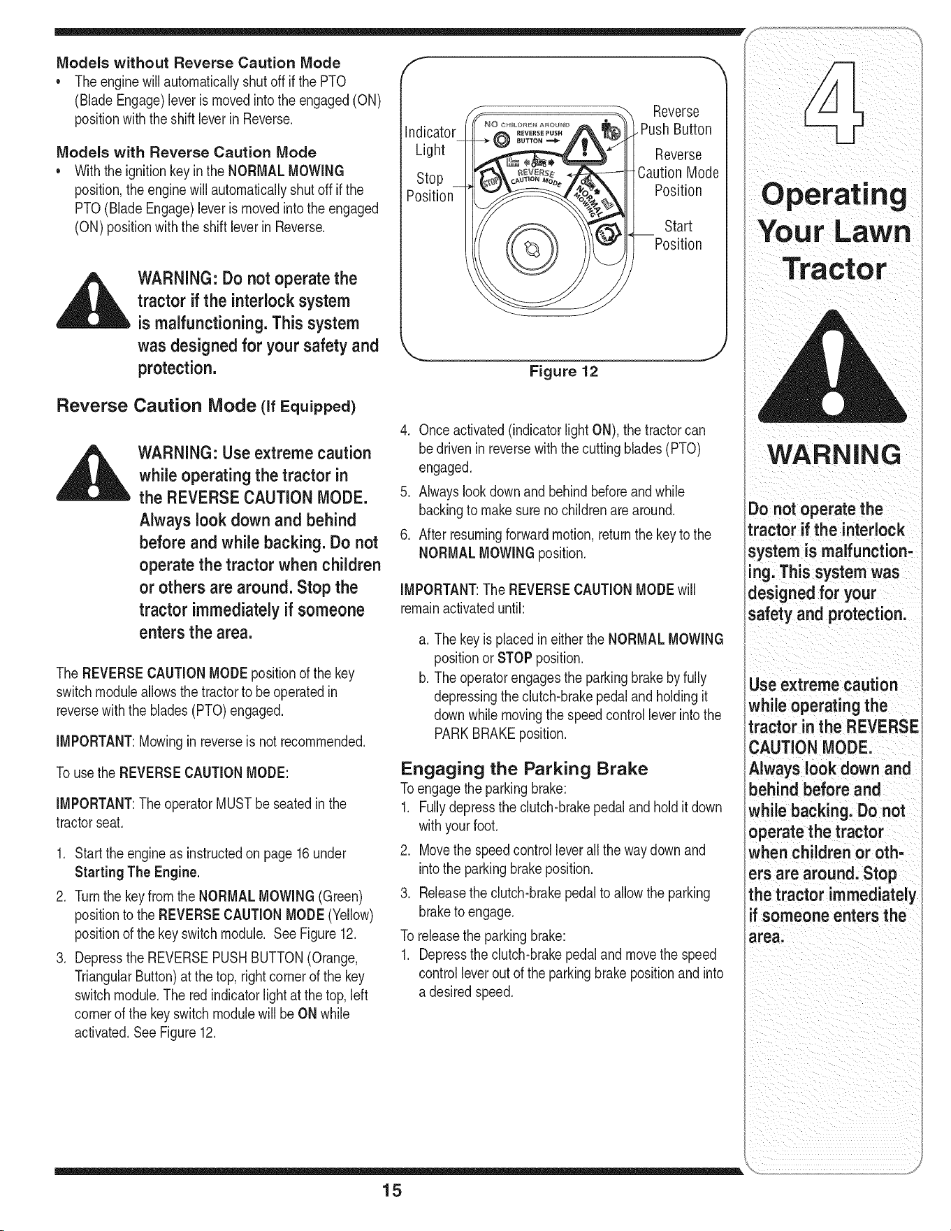
Reverse Caution Mode (if Equipped)
WARNING: Use extreme caution
while operating the tractor in
the REVERSE CAUTION MODE.
Always look down and behind
before and while backing. Do not
operate the tractor when children
or others are around, Stop the
tractor immediately if someone
enters the area.
The REVERSECAUTIONMODEpositionof the key
switchmoduleallows thetractorto be operatedin
reversewiththe blades(PTO)engaged.
IMPORTANT:Mowinginreverseis notrecommended.
Tousethe REVERSECAUTIONMODE:
IMPORTANT:The operatorMUSTbe seatedinthe
tractorseat.
1. Startthe engineas instructedon page16under
Starting The Engine.
2. Turnthe key from the NORMALMOWING(Green)
positionto the REVERSECAUTIONMODE(Yellow)
positionof the key switchmodule. SeeFigure12.
3. Depressthe REVERSEPUSHBUTTON(Orange,
TriangularButton)at the top, rightcornerof the key
switchmodule.The red indicatorlightat thetop,left
cornerof the keyswitch modulewill be ONwhile
activated.See Figure12.
F
Indicator
Light
Stop
Position
©
Reverse
. PushButton
Reverse
CautionMode
Position
Start
Position
Figure 12
4. Onceactivated(indicatorlight ON),the tractorcan
bedriveninreversewiththecutting blades(PTO)
engaged.
5. Alwayslookdownand behindbeforeandwhile
backingto make surenochildrenare around.
6. Afterresumingforwardmotion,returnthe key to the
NORMALMOWINGposition.
IMPORTANT:The REVERSECAUTIONMODEwill
remainactivateduntil:
a. The key is placedineitherthe NORMALMOWING
positionor STOPposition.
b. The operatorengagesthe parkingbrakebyfully
depressingthe clutch-brakepedaland holdingit
downwhile movingthe speedcontrolleverintothe
PARKBRAKEposition.
Engaging the Parking Brake
Toengagethe parkingbrake:
1. Fullydepressthe clutch-brakepedaland hold it down
withyourfoot.
2. Movethe speedcontrolleverall the waydownand
intothe parkingbrakeposition.
3. Releasethe clutch-brakepedalto allowthe parking
braketo engage.
To releasethe parkingbrake:
1. Depressthe clutch-brakepedaland movethe speed
controlleverout of the parkingbrakepositionand into
a desiredspeed.
15
_ _ii ii_i i_iii_ii_ i?_i_i_i_ii_ ii__
WARNING
Do not operate the
tractor if the interlock
system is malfunction-
ing. This system was
designed for your
safety and protection.
Use extreme caution
while operating the
tractor in the REVERSE
CAUTION MODE.
Always look down and
behind before and
while backing. Do not
operate the tractor
when children or oth-
ers are around. Stop
the tractor immediately
f someone enters the
area.
YoUr LaWn
i
Tractor
WARNING
Keep hands and feet
away from the dis-
charge opening of the
cutting deck.
Do not operate the
tractor if the interlock
system is malfunction-
ing.This system was
designed for your
safety and protection.
if you strike a foreign
object, stop the
engine, disconnect
the spark plug wire(s)
and ground against
the engine. Thoroughly
inspectthe machine
for any damage. Repair
the damage before
restarting and operat-
ing.
Setting the Cutting Height
1. Selectthe heightpositionof the cuttingdeckby
placingthe deck liftleverinany of the six different
cuttingheightnotchesonthe rightsideof the fender.
2. Adjustthe deck wheels,if equipped,so that they are
betweenl_-inchand Y2-inchabovethe groundwhen
thetractor is ona smooth,flat surfacesuchas a
driveway.
WARNING: Keep hands and feet
away from the discharge open-
ing of the cutting deck.
NOTE:Onmodelsso equipped,thedeckwheelsare an
anti-scalpfeatureof thedeck and are notdesignedto
supportthe weightof the cuttingdeck.
Referto Levelingthe Deckonpage20of this manual
for moredetailedinstructionsregardingvariousdeck
adjustments.
Starting the Engine
,,__ WARNING" Do not operate the
tractor if the interlock system is
malfunctioning. This system was
designed for your safety and
protection.
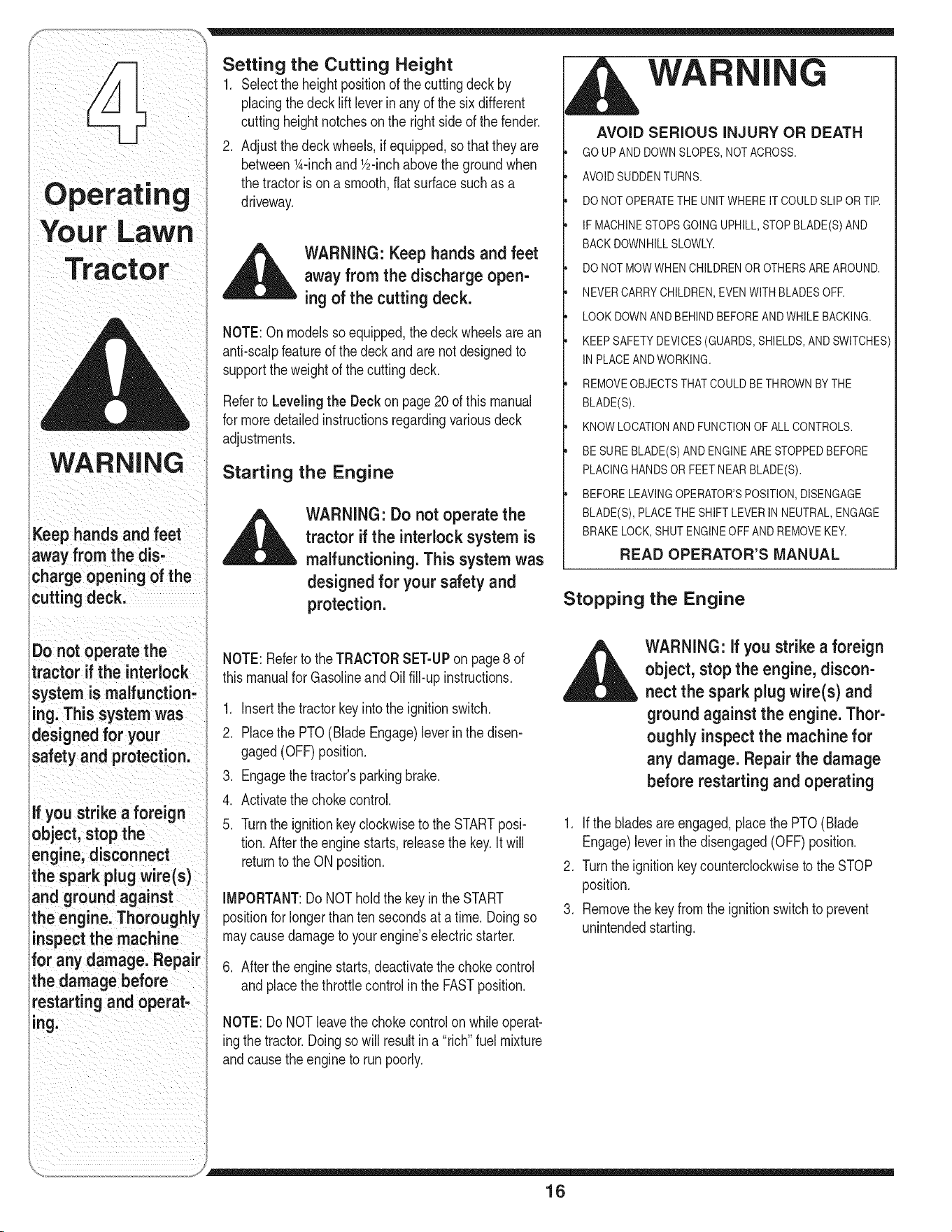
I G
AVOID SERIOUS INJURY OR DEATH
GO UPAND DOWNSLOPES,NOT ACROSS.
AVOIDSUDDENTURNS.
DO NOT OPERATETHEUNITWHERE IT COULDSLIPOR TIE
IF MACHINESTOPSGOINGUPHILL,STOP BLADE(S) AND
BACK DOWNHILLSLOWLY.
DO NOT MOWWHEN CHILDRENOROTHERSARE AROUND.
NEVER CARRYCHILDREN,EVENWITH BLADESOFR
LOOK DOWNAND BEHIND BEFOREAND WHILE BACKING.
KEEP SAFETY DEVICES(GUARDS,SHIELDS,AND SWITCHES)
IN PLACEAND WORKING.
REMOVEOBJECTSTHATCOULDBE THROWNBY THE
BLADE(S).
KNOW LOCATIONAND FUNCTIONOF ALL CONTROLS.
BE SURE BLADE(S)AND ENGINEARE STOPPEDBEFORE
PLACING HANDSOR FEETNEAR BLADE(S).
BEFORE LEAVINGOPERATOR'SPOSITION,DISENGAGE
BLADE(S), PLACETHE SHIFTLEVERIN NEUTRAL,ENGAGE
BRAKE LOCK, SHUT ENGINEOFF AND REMOVEKEY.
READ OPERATOR'S MANUAL
Stopping the Engine
NOTE:Referto the TRACTORSET-UPon page8 of
thismanualfor GasolineandOil fill-upinstructions.
1. Insertthe tractorkey intothe ignitionswitch.
2. Placethe PTO(BladeEngage)leverin the disen-
gaged(OFF)position.
3. Engagethetractor'sparkingbrake.
4. Activatethe chokecontrol.
5. Turnthe ignitionkey clockwiseto the STARTposi-
tion.Afterthe engine starts,releasethe key.Itwill
returnto the ONposition.
IMPORTANT:DoNOTholdthe keyin the START
positionfor longerthanten secondsat a time. Doingso
maycausedamageto yourengine'selectricstarter.
6. Afterthe engine starts,deactivatethe chokecontrol
andplacethe throttlecontrol in the FASTposition.
__ ARNING: if you strike a foreign
object, stop the engine, discon-
nect the spark plug wire(s) and
ground against the engine. Thor-
oughly inspectthe machine for
any damage. Repair the damage
before restarting and operating
1. If the bladesare engaged,placethe PTO(Blade
Engage)leverinthe disengaged(OFF)position.
2. Turnthe ignitionkey counterclockwiseto the STOP
position.
3. Removethe keyfrom the ignitionswitchto prevent
unintendedstarting.
NOTE:Do NOTleavethe chokecontrolonwhile operat-
ingthe tractor.Doingsowill result in a "rich"fuelmixture
andcausethe engineto run poorly.
16
Driving The Tractor
WARNING: Avoid sudden starts,
e×-cessivespeed and sudden
stops.
WARNING: Do not leave the seat
of the tractor without first plac-
ingthe PTO (Blade Engage) lever
inthe disengaged (OFF) posi-
tion, depressing the brake pedal
and engaging the parking brake.
if leaving the tractor unattended,
also turn the ignition key off and
remove the key.
Always look down and behind
before and while backing up to
avoid a back-over accident.
1. Depressthe brakepedalto releasetheparkingbrake
andlet the pedalup.
2. Movethe throttleleverintothe FAST(rabbit)position.
3. Placethe shiftleverin eitherthe FORWARDor
REVERSEposition.
IMPORTANT:DoNOTuse the shift leverto changethe
directionof travelwhenthe tractoris in motion.Always
usethe brakepedalto bringthe tractorto a complete
stopbeforeshifting.
4. Releasethe parkingbrakebydepressingthe clutch-
brakepedalandpositioningthe speedcontrolleverin
desiredposition.
NOTE:Whenoperatingthe unit initially,there willbe little
differencebetweenthe highesttwo speedsuntilafter the
beltshaveseatedthemselvesinto the pulleysduringthe
break-inperiod.
_ ARNING: Before leaving the
operator's positionfor any
reason, disengage the blades,
place the shift lever in neutral,
engage the parking brake, shut
engine off and remove the key.
IMPORTANT:Whenstoppingthe tractorfor anyreason
whileona grass surface,always:
1. Placethe shift leverin neutral,
2. Engagethe parkingbrake,
3. Shutengineoff and removethe key.
Doingsowill minimizethe possibilityof havingyourlawn
"browned"by hot exhaustfromyourtractor's running
engine.
If unit stalls with speedcontrolin highspeed,or if unit
willnot operatewithspeedcontrolleverin a lowspeed
position,proceedas follows:
1. Placeshiftleverin NEUTRAL.
2. Restartengine.
3. Placespeedcontrol leverinhighestspeedposition.
4. Releaseclutch-brakepedalfully.
5. Depressclutch-brakepedal.
6. Placespeedcontrol leverindesiredposition.
7. Placeshiftleverin eitherFORWARDor REVERSE,
andfollownormaloperatingprocedures.
IMPORTANT:First-timeoperatorsshouldusespeed
positions1or2. Becomecompletelyfamiliarwiththe
tractor'soperationand controlsbeforeoperatingthe
tractorinhigherspeedpositions.
.
6.
Releaseclutch-brakepedalslowlyto putunit into
motion.
The lawntractoris broughtto a stopbydepressing
theclutch-brakepedal.
WARNING
Avoid sudden starts,
ex-cessive speed and
sudden stops.
Do not leave the seat
of the tractor without
first placingthe PTO
(Blade Engage)lever in
the disengaged (OFF)
position, depressing
the brake pedal and
engaging the parking
brake, if leaving the
tractor unattended,
also turn the ignition
key off and remove the
key.
Always look down
and behind before
and while backing up
to avoid a back-over
_ccident.
17
WARNING
Do not mow on inclines
with a slope in excess
of 15 degrees (a rise
of approximately 2-1/2
feet every 10 feet). The
tractor could overturn
and cause serious
injury.
To help avoid blade
;ontact or a thrown
object injury, keep
bystanders, helpers,
;hildren and pets at
least 75 feet from the
machine while it is in
operation. Stop ma-
;hine if anyoneenters
the area.
Driving On Slopes
Referto the SLOPEGAUGEon page3 to helpdeter-
mineslopeswhereyou mayoperatethe tractorsafely.
,_ WARNING: Do not mow on
inclineswith a slope in excess
of 15 degrees (a rise of approxi-
mately 2-1/2 feet every 10feet).
The tractor could overturn and
cause serious injury.
• Mow up anddownslopes,NEVERacross.
• Exerciseextremecautionwhenchangingdirection
on slopes.
• Watchfor holes, ruts,bumps,rocks,or otherhidden
objects.Uneventerraincouldoverturnthe machine.
Tallgrasscan hideobstacles.
• Avoidturnswhendrivingona slope. If a turn must
be made,turn downthe slope.Turningupa slope
greatlyincreasesthechanceof a roll over.
• Avoidstoppingwhendrivingup a slope.If it is
necessaryto stop whiledrivingup a slope, startup
smoothlyandcarefullyto reducethe possibilityof
flippingthe tractoroverbackward.
Engaging the Blades
Engagingthe PTO(BladeEngage)transferspowerto
thecutting deckor other(separatelyavailable)attach-
ments.Toengagethe blades,proceedas follows:
1. Movethe throttlecontrolleverto the FAST(rabbit)
position.
2. Graspthe PTO(BladeEngage)leverand pivotit all
thewayforwardinto theengaged(ON) position.
3. Keepthe throttleleverinthe FAST(rabbit)position
for the mostefficientuseof the cuttingdeck or other
(separatelyavailable)attachments
iMPORTANT:Models with Reverse Caution Mode:
Theenginewill automaticallyshutoff ifthe PTOis
engagedwiththe shift leverin positionfor reversetravel
withthe ignitionkeyinthe NORMALMOWINGposition.
Models withoutReverseCautionMode:
The PTO(BladeEngage)levermust be in thedisen-
gaged(OFF)positionwhen startingthe engine,when
travelingin reverse,and if the operatorleavesthe seat.
Referto SafetyinterlockSwitcheson page 14.
Using the Deck Lift Lever
Toraisethe cuttingdeck,movethe deck lift leverto the
left,thenplaceit inthe notchbestsuitedfor yourapplica-
tion.Referto SettingThe CuttingHeightearlierinthis
section.
Mowing
WARNING: To help avoid blade
contact or a thrown object injury,
keep bystanders, helpers, children
and pets at least 75 feet from the
machine while it is in operation.
Stop machine if anyone enters the
area.
Thefollowinginformationwill be helpfulwhenusingthe
cuttingdeckwith yourtractor:
WARNING: Plan your mowing
pattern to avoid discharge of
materials toward roads, sidewalks,
bystanders and the like. Also,
avoid discharging material against
a wall or obstruction which may
cause discharged material to
ricochet back toward the operator.
• Do not mowat high groundspeed,especiallyifa
mulchkit or grass collectoris installed.
• For best resultsit is recommendedthat the firsttwo
lapsbe cut with the dischargethrowntowardsthe
center.Afterthe first two laps, reversethedirectionto
throwthe dischargeto the outsidefor the balanceof
cutting.Thiswill givea betterappearanceto the lawn.
• Do notcut thegrasstoo short.Shortgrass invites
weedgrowthandyellowsquicklyindry weather.
• Mowingshouldalwaysbe done with theengineat full
throttle.
Underheavierconditionsit may be necessaryto go
backoverthecut areaa secondtimeto get a clean
cut.
18
• Do NOTattemptto mowheavybrushand weedsand _ _ " --
extremelytall grass.Yourtractoris designedto mow /A I
awns,NOTdearbrush //I
• Keepthe bladessharpand replacethebladeswhen "i.: ....",,, [J
worn.Referto Cutting Blades on page25 of this / '
manualfor properblade sharpeninginstructions.
Mulching (If Equipped)
Selectmodelscomeequippedwitha mulchkit which
incorporatesspecialblades,alreadystandardon the
tractor,ina processof recirculatinggrassclippings
repeatedlybeneaththe cuttingdeck.Theultra-fine
clippingsarethen forcedback intothe lawnwherethey
actas a naturalfertilizer.
Observethe followingpointsfor the best resultswhen
mulching:
• Neverattemptto mulchif the lawnis damp.Wet grass
tendsto stickto theundersideof the cuttingdeck
preventingpropermulchingof the clippings.
• Do NOTattemptto mulchmorethan 1/3the total
heightof the grassor approximately1-1/2inches.
Doingso willcause theclippingsto clump up beneath
thedeckand notbe mulchedeffectively.
• Maintaina slow groundspeedto allowthe grass
clippingsmoretime to effectivelybe mulched.
• Alwayspositionthe throttlecontrolleverinthe FAST
(rabbit)positionandallowit to remaintherewhile
mowing.Failingto keepthe engineat full throttle
placesstrainon the tractor'sengineand doesnot
allowthe bladesto properlymulchgrass.
Figure 13
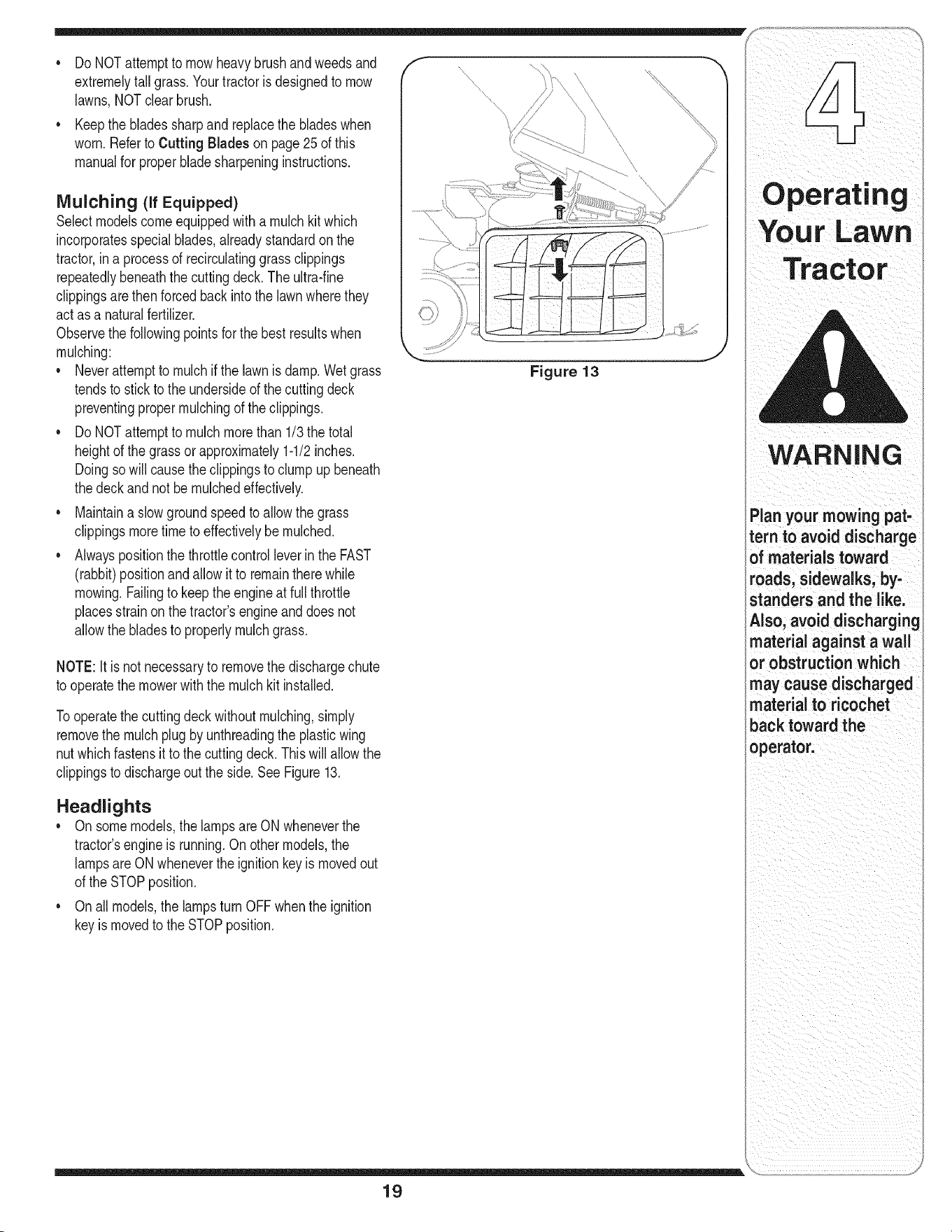
NOTE:It is not necessaryto removethe dischargechute
to operatethe mowerwith the mulchkit installed.
Tooperatethe cuttingdeck withoutmulching,simply
removethe mulch plug byunthreadingthe plasticwing
nutwhichfastensit to the cuttingdeck.This will allowthe
clippingsto dischargeout the side.See Figure13.
Headlights
• Onsomemodels,the lampsare ON wheneverthe
tractor'sengineisrunning.On othermodels,the
lampsareON wheneverthe ignitionkey is movedout
of the STOPposition.
• Onall models,the lampsturn OFFwhenthe ignition
keyismovedto the STOPposition.
19
Operating
WARNING
Planyour mowing pat-
tern to avoid discharge
of materials toward
roads, sidewalks, by-
standers and the like.
Also, avoid discharging
_aterial against a wall
_r obstruction which
may cause discharged
aterial to ricochet
back toward the
operator.
WARNING
Neverattemptto
make any adjust-
ments while the
engine is running,
except where speci-
i fied in the operator's
manual.
i Never attempt to
iadjust the brakes
_wh ie the engine
i is running. Always
idisengage PTO, move
::shift lever into neutral
position, stop engine
and remove key to
iprevent unintended
istarting.
Figure 14
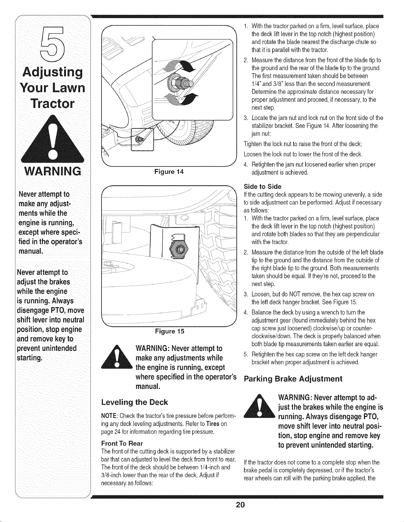
1. Withthe tractorparkedona firm,levelsurface,place
the deck lift leverin the top notch(highestposition)
androtatethe blade nearestthe dischargechute so
thatitis parallelwiththe tractor.
2. Measurethe distancefromthe frontofthe bladetip to
the groundand the rearof the blade tip to the ground.
Thefirst measurementtakenshouldbe between
1/4"and 3/8" less than thesecondmeasurement.
Determinethe approximatedistancenecessaryfor
properadjustmentandproceed,if necessary,to the
nextstep.
3. Locatethejam nut andlocknut onthe frontsideof the
stabilizerbracket.See Figure14.After looseningthe
jam nut:
Tightenthe lock nutto raisethefront of the deck;
Loosenthe lock nut to lowerthefrontof the deck.
4. Retightenthe jam nut loosenedearlierwhen proper
adjustmentis achieved.
Figure 15
,_ WARNING: Never attempt to
make any adjustments while
the engine is running, except
where specified in the operator's
manual.
Leveling the Deck
NOTE:Checkthe tractor'stire pressurebeforeperform-
inganydeck levelingadjustments.Referto Tires on
page24 for informationregardingtire pressure.
Front To Rear
Thefrontof the cuttingdeckis supportedbya stabilizer
barthatcanadjustedto levelthe deckfromfrontto rear.
Thefrontof the deckshouldbebetween1/4-inchand
3/8-inchlowerthanthe rear of the deck.Adjustif
necessaryas follows:
Side to Side
If the cuttingdeckappearsto be mowingunevenly,a side
to side adjustmentcan be performed.Adjustif necessary
as follows:
1. Withthe tractorparkedona firm,levelsurface,place
the deck lift leverin the top notch(highestposition)
androtateboth bladesso thattheyareperpendicular
withthe tractor.
2. Measurethe distancefromthe outsideof the leftblade
tip to the groundandthe distancefromtheoutside of
the rightbladetip to theground.Bothmeasurements
takenshouldbeequal. Ifthey'renot,proceedto the
nextstep.
3. Loosen,butdo NOT remove,the hexcap screwon
the left deckhangerbracket.SeeFigure15.
4. Balancethe deck by usinga wrenchto turn the
adjustmentgear (foundimmediatelybehindthe hex
cap screwjust loosened)clockwise/uporcounter-
clockwise/down.Thedeck is properlybalancedwhen
bothbladetip measurementstakenearlierareequal.
5. Retightenthe hex capscrewonthe left deck hanger
bracketwhenproperadjustmentis achieved.
Parking Brake Adjustment
_ ARNING" Never attempt to ad-
just the brakes while the engine is
running. Always disengage PTO,
move shift lever into neutral posi-
tion, stop engine and remove key
to prevent unintended starting.
If the tractordoes notcometo a completestopwhenthe
brakepedalis completelydepressed,or if the tractor's
rearwheelscan roll withthe parkingbrakeapplied,the
2O
brakeis in need of adjustment.Thebrakedisccan be
foundon the rightsideof thetransmissionin the rear of
the tractor.Adjustif necessaryas follows:
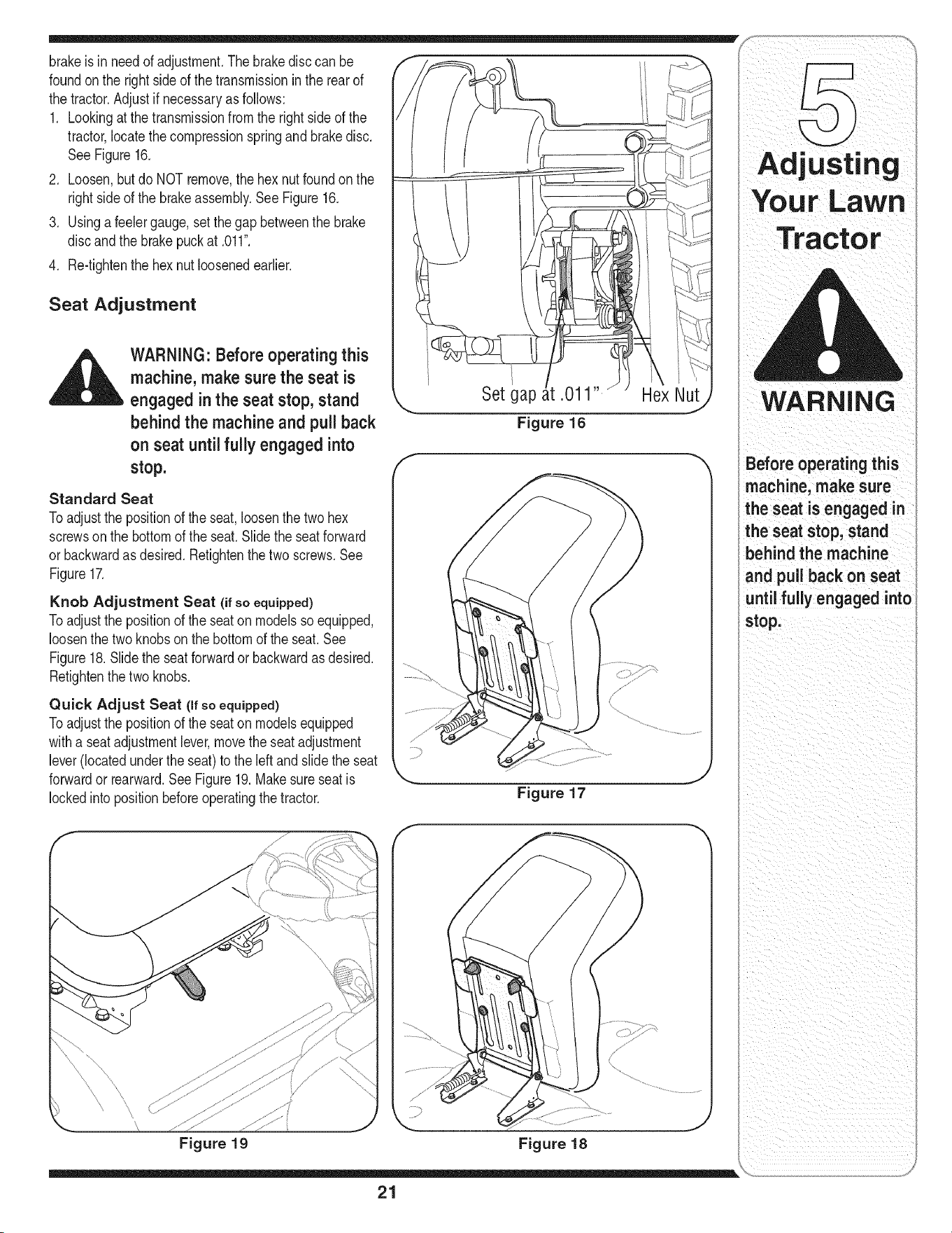
1. Lookingat thetransmissionfrom the right sideof the
tractor,locatethe compressionspringandbrakedisc.
See Figure16.
2. Loosen,but do NOTremove,the hex nutfoundon the
rightsideof the brakeassembly.See Figure16.
3. Usinga feelergauge,setthe gapbetweenthe brake
discandthe brakepuckat .011".
4. Re-tightenthe hexnut loosenedearlier.
Seat Adjustment
_ ARNING: Before operating this
machine, make sure the seat is
engaged in the seat stop, stand
behind the machine and pull back
on seat until fully engaged into
stop.
Standard Seat
Toadjustthe positionof the seat,loosenthe two hex
screwson the bottomof the seat.Slidethe seatforward
or backwardas desired.Retightenthe two screws.See
Figure17.
Knob Adjustment Seat (if so equipped)
Toadjustthe positionof the seaton modelsso equipped,
loosenthe twoknobson the bottomof theseat. See
Figure18.Slidethe seatforwardor backwardas desired.
Retightenthe two knobs.
Quick Adjust Seat (if so equipped)
Toadjustthe positionof the seaton modelsequipped
witha seat adjustmentlever,movethe seatadjustment
lever(locatedundertheseat)to the leftand slidethe seat
forwardor rearward.See Figure19.Makesureseatis
lockedintopositionbeforeoperatingthe tractor.
Set gap
Figure 16
Hex Nut
Figure 17
.....J
\
Figure 19 Figure 18
21
Adjusting
urLawn
WARNING
Before operating this
machine, make sure
the seat is engaged in
the seat stop, stand
behind the machine
and pull back on seat
until fully engaged into
stop.
WARNING
any maintenance or
repairs, disengage
PTO, move shift lever
intoneutral position,
set parkingbrake, stop
engine and remove key
o preventu nintended
_tarting!
Before lubricatingi
repairing, or inspect,
ing, always disengage
PTOImove shift lever
into neutral position,
set parking brake, stop
engineandremovekey
to prevent unintended
startingl
NOTE:Dependingon
the engine model found
Onyour tractorl itmay
be necessary to remove
the tractor!s side panel
in OrdertO replace the
oil filter (if so equipped):
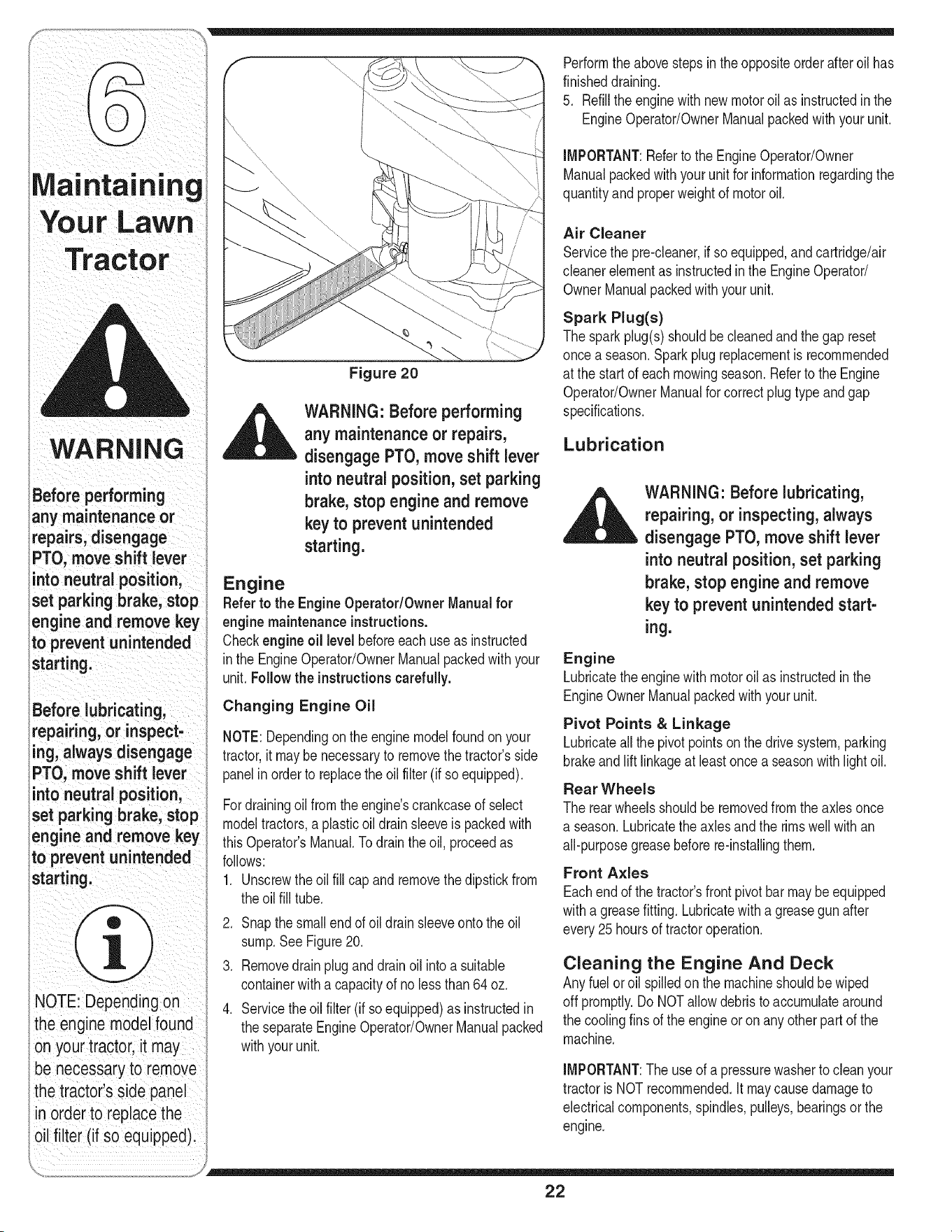
Figure 20
,_ WARNING: Before performing
any maintenance or repairs,
disengage PTO, move shift lever
into neutral position, set parking
brake, stop engine and remove
key to prevent unintended
starting.
Engine
Referto the EngineOperator/Owner Manualfor
engine maintenance instructions.
Checkengine oil levelbeforeeachuseas instructed
inthe EngineOperator/OwnerManualpackedwith your
unit.Follow the instructionscarefully.
Changing Engine Oil
NOTE:Dependingonthe enginemodelfoundon your
tractor,it maybenecessaryto removethe tractor'sside
panelin order to replacethe oil filter (if so equipped).
Fordrainingoilfromthe engine'scrankcaseof select
modeltractors,a plasticoil drain sleeveis packedwith
thisOperator'sManual.Todrainthe oil, proceedas
follows:
1. Unscrewthe oilfill capand removethe dipstickfrom
theoil fill tube.
2. Snapthe small end of oil drain sleeveontothe oil
sump.SeeFigure20.
3. Removedrainpluganddrainoil intoa suitable
containerwitha capacityof no lessthan64 oz.
4. Servicethe oil filter (if soequipped)as instructedin
the separateEngineOperator/OwnerManualpacked
withyourunit.
Performthe abovestepsinthe oppositeorderafteroil has
finisheddraining.
5. Refillthe enginewith newmotoroil as instructedinthe
EngineOperator/OwnerManualpackedwith your unit.
IMPORTANT:Referto the EngineOperator/Owner
Manualpackedwith yourunit for informationregardingthe
quantityand properweight of motoroil.
Air Cleaner
Servicethe pre-cleaner,if soequipped,andcartridge/air
cleanerelementas instructedin the EngineOperator/
OwnerManualpackedwithyour unit.
Spark Plug(s)
Thesparkplug(s)shouldbe cleanedand thegap reset
oncea season.Sparkplugreplacementis recommended
at the startof each mowingseason.Referto the Engine
Operator/OwnerManualfor correctplugtypeandgap
specifications.
Lubrication
WARNING: Before lubricating,
repairing, or inspecting, always
disengage PTO, move shift lever
into neutral position, set parking
brake, stop engine and remove
key to prevent unintended start-
ing.
Engine
Lubricatethe enginewith motoroil as instructedin the
EngineOwnerManualpackedwith yourunit.
Pivot Points & Linkage
Lubricateall the pivotpoints on the drivesystem,parking
brakeand lift linkageat least oncea seasonwith lightoil.
Rear Wheels
The rearwheelsshouldbe removedfromthe axlesonce
a season.Lubricatethe axles and the rimswell with an
all-purposegreasebeforere-installingthem.
Front Axles
Eachendof the tractor'sfrontpivotbarmaybeequipped
witha greasefitting.Lubricatewitha greasegunafter
every25 hoursof tractoroperation.
Cleaning the Engine And Deck
Anyfuel oroil spilledon the machineshouldbe wiped
off promptly.Do NOTallowdebristo accumulatearound
the coolingfins of the engineor on any otherpart of the
machine.
IMPORTANT:The useof a pressurewasherto cleanyour
tractoris NOTrecommended.It maycause damageto
electricalcomponents,spindles,pulleys,bearingsor the
engine.
22
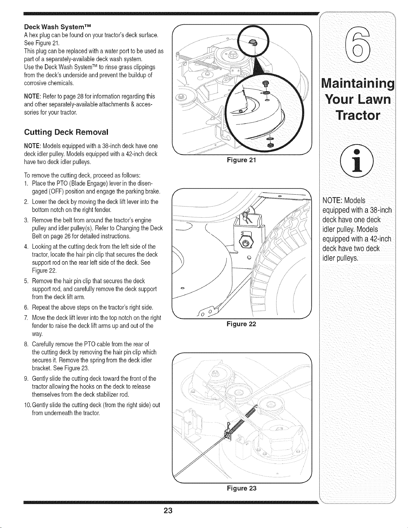
Deck Wash System TM
A hexplug can be foundon yourtractor'sdecksurface.
SeeFigure21.
Thisplugcanbe replacedwitha waterport to be usedas
part of a separately-availabledeckwash system.
Usethe DeckWashSystemTM to rinsegrassclippings
fromthe deck'sundersideand preventthe buildupof
corrosivechemicals.
NOTE:Referto page28for informationregardingthis
andotherseparately-availableattachments& acces-
soriesfor yourtractor.
Cutting Deck Removal
NOTE:Modelsequippedwitha 38-inchdeck haveone
deckidlerpulley.Modelsequippedwitha 42-inchdeck
havetwodeckidlerpulleys.
To removethecuttingdeck, proceedas follows:
1. Placethe PTO(BladeEngage)leverin the disen-
gaged(OFF)positionandengagethe parkingbrake.
2. Lowerthe deck by movingthedeck liftleverinto the
bottomnotchonthe rightfender.
3. Removethe beltfromaroundthetractor'sengine
pulleyandidlerpulley(s).Referto Changingthe Deck
Belton page26 for detailedinstructions.
4. Lookingat the cuttingdeck from theleft sideof the
tractor,locatethe hair pin clip that securesthe deck
supportrodon the rear left sideof the deck. See
Figure22.
5. Removethe hairpinclipthat securesthedeck
supportrod, and carefullyremovethe decksupport
fromthe deck lift arm.
6. Repeattheabovestepson thetractor'srightside.
7. Movethe deck lift leverintothe top notchon the right
fenderto raisethe deck lift armsupandout of the
way.
8. Carefullyremovethe PTOcablefromthe rearof
the cuttingdeckby removingthe hair pinclip which
securesit. Removethe springfrom the deck idler
bracket.SeeFigure23.
9. Gentlyslidethe cuttingdecktowardthe frontof the
tractorallowingthe hookson the deck to release
themselvesfromthedeckstabilizerrod.
10.Gentlyslidethe cuttingdeck(fromthe rightside)out
fromunderneaththe tractor.
Figure 21
\
Figure 22
Figure 23
23
tOTE: Models
equipped with a 38-inch
deck have one deck
idler pulley.Models
eau_ppedwith a 42-inch
deck have two deck
idler pulleys.

Tires Jump Starting
WARNING
Never exceed the
maximum inflation
pressure shown on the
sidewall of the tire.
Batteries give off an
explosive gas while
charging. Charge bat=
tery ina well ventilated
area and keep away
from an open flame
or pilot light as on a
water heater, space
heater, furnace, clothes
dryer or other gas
appliances.
Always use a fuse with
the same amperage
capacity for replace=
merit.
,_ WARNING: Never exceedthe ,_
maximum inflation pressure
shown on the sidewall of tire.
The recommendedoperatingtire pressureis:
• Approximately10 psifor the reartires
• Approximately14psi for the fronttires
IMPORTANT:Referto the tire sidewallforexacttire
manufacturer'srecommendedormaximumpsi. Do not
overinflate.Uneventirepressurecouldcausethe cutting
deckto mowunevenly.
Battery
The batteryis sealedandis maintenance-free.Acid
levelscannotbechecked.
• Alwayskeepthe batterycablesandterminalsclean
andfreeof corrosivebuild-up.
• Aftercleaningthe batteryandterminals,apply a light
coatof petroleumjellyor greaseto bothterminals.
• Alwayskeepthe rubberboot positionedoverthe
positiveterminalto preventshorting.
IMPORTANT:Ifremovingthe batteryfor anyreason,
disconnectthe NEGATIVE(Black)wire fromit'sterminal
first,followedby the POSITIVE(Red)wire.When
re-installingthe battery,alwaysconnectthe POSITIVE
(Red)wire itsterminalfirst,followedby the NEGATIVE
(Black)wire.Becertainthatthewiresareconnectedto
thecorrectterminals;reversingthemcouldchangethe
polarityandresultindamageto your engine'salternat-
ingsystem.
Charging
If thetractorhas not beenput into usefor anextended
periodof time,chargethe batterywith an automotive-
type 12-voltchargerfora minimumof one hour at six
amps.
WARNING: Batteries give off an
explosive gas while charging.
Charge battery in a well venti-
lated area and keep away from
an open flame or pilot light as
on a water heater, space heater,
furnace, clothes dryer or other
gas appliances.
WARNING:When removing or
installingthe battery, follow
these instructionsto prevent the
screwdriver from shorting against
the frame.
IMPORTANT:Neverjump yourtractor'sdeadbatterywith
the batteryof a runningvehicle.
1. Connectend of one jumpercableto the positive
terminalof the good battery,thenthe otherendto the
positiveterminalof the dead battery.
2. Connectthe otherjumpercable to the negative
terminalof the good battery,thento the frame of the
unit with the dead battery.
_ WARNING" Failure to use this
procedure could cause sparking,
and the gas in either battery could
explode.
Cleaning
Cleanthe batteryby removingit fromthe tractorand
washingwitha bakingsodaand water solution.If neces-
sary,scrapethe batteryterminalswith a wire brushto
removedeposits.Coatterminalsandexposedwiringwith
greaseor petroleumjelly to preventcorrosion.
Battery Failures
Somecommoncausesfor batteryfailureare:
• incorrectinitialactivation • undercharging
• overcharging • corrodedconnections
• freezing
These failures are NOTcovered by your tractor's
warranty.
Fuse
One20AMPfuseis installedin yourtractor'swiring har-
nessto protectthe tractor'selectricalsystemfrom damage
causedby excessiveamperage.
If the electricalsystemdoesnot function,or yourtractor's
enginewill notcrank,first checkto be certainthatthe fuse
has notblown.Itcan befoundunderthehood mounted
behindthe dashpanelon the rightside.
,_ WARNING: Always use a fuse with
the same amperage capacity for
replacement.
24
S
Cutting Blades f
WARNING: Be sure to shut
the engine off, remove ignition
key, disconnect the spark plug
wire(s) and ground against the
engine to prevent unintended
starting before removing the cut-
ring blade(s) for sharpening or
replacement. Protect your hands
by using heavy gloves or a rag to
grasp the cutting blade.
WARNING: Periodically inspect
the blade spindles for cracks or
damage, especially if you strike a
foreign object. Replace immedi-
ately if damaged.
The bladesmay be removedas follows.
1. Removethe deck from beneaththe tractor,(referto
CuttingDeckRemovalon page23) thengentlyflip
thedeckoverto exposeits underside.
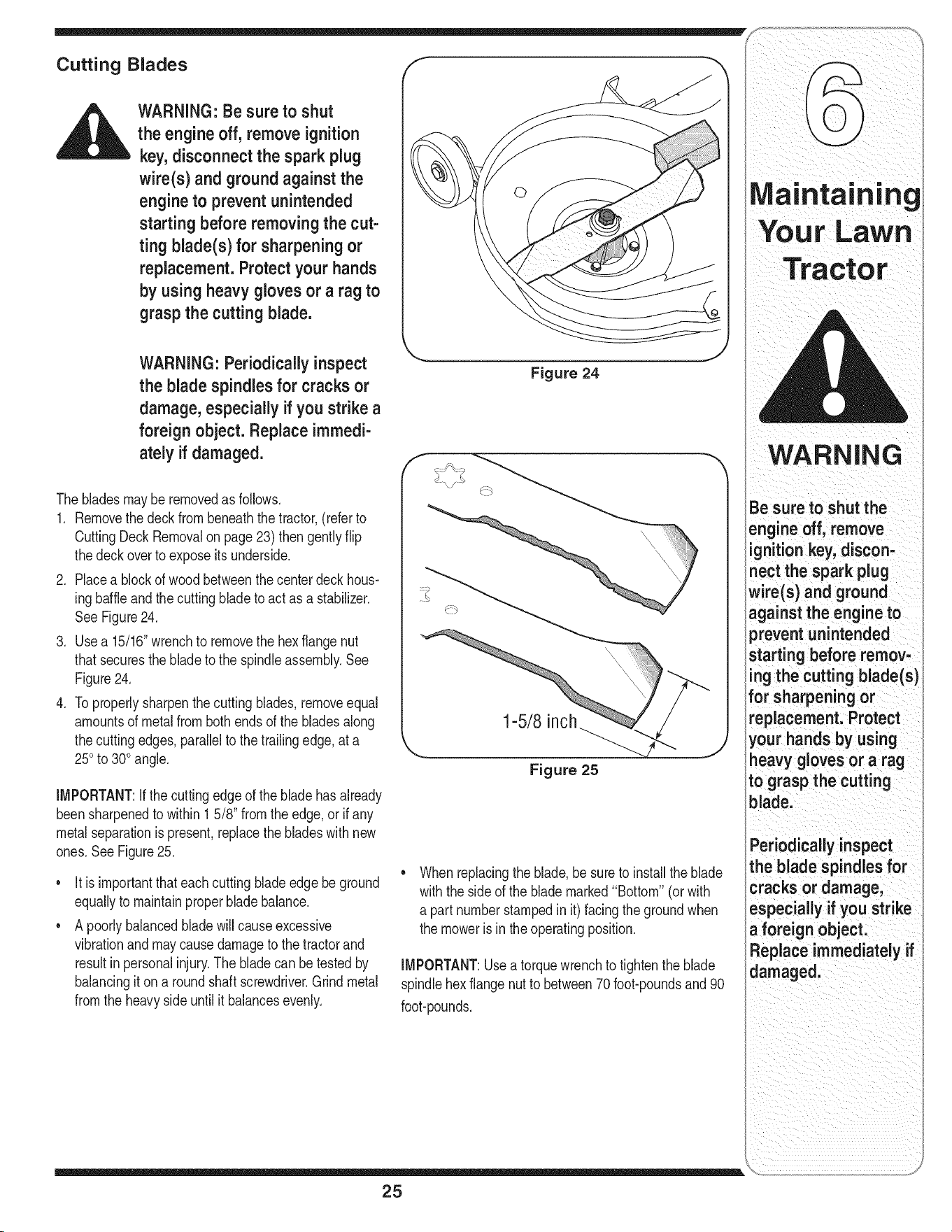
2. Placea blockof wood betweenthe centerdeck hous-
ingbaffleandthe cuttingbladeto act as a stabilizer,
SeeFigure24,
3, Usea 15/16"wrenchto removethe hexflangenut
thatsecuresthe bladeto the spindleassembly.See
Figure24,
4. Toproperlysharpenthe cuttingblades,removeequal
amountsof metalfrom bothends of the bladesalong
thecutting edges,parallelto the trailingedge,at a
250to 300angle,
IMPORTANT:Ifthe cuttingedgeof the bladehasalready
beensharpenedto within 1 5/8" fromtheedge,or if any
metalseparationis present,replacethe bladeswith new
ones,SeeFigure25,
It isimportantthateachcuttingblade edge be ground
equallyto maintainproperblade balance.
A poorlybalancedbladewill causeexcessive
vibrationand maycausedamageto thetractorand
resultinpersonalinjury,The bladecan be testedby
balancingit on a roundshaftscrewdriver.Grind metal
fromthe heavysideuntil it balancesevenly.
Figure 24
1-5/8 inch
Figure 25
Whenreplacingthe blade,besureto installthe blade
withtheside of the blademarked"Bottom" (or with
apart numberstampedinit) facing the groundwhen
themoweris in the operatingposition.
IMPORTANT:Useatorquewrenchto tightenthe blade
spindlehexflange nutto between70foot-poundsand90
foot-pounds.
WARNING
Be sure to shut the
engine off, remove
ignition key, discon-
nect the spark plug
wire(s) and ground
against the engine to
prevent unintended
starting before remov-
ing the cutting blade(s)
for sharpening or
replacement. Protect
your hands by using
heavy gloves or a rag
to grasp the cutting
blacle,
Periodically inspect
the blade spindles for
cracks or damage,
especially if you strike
a foreign object.
Replace immediately if
damaged.
25

i ioto°i°g
WARNING
Be sure to shutthe
engine off, remove ig-
nition key, disconnect
the spark plug wire(s)
and ground against
the engine to prevent
unintendedstarting
before removingthe
belt(s).
Avoid the possibility of
a pinching injury.Do
not place your fingers
on the idler spring or
between the belt and a
pulleywhile removing
the belt.
Figure 26
Changing the Deck Belt & PTO Belt
_ WARNING" Be sure to shut
the engine off, remove ignition
key,disconnect the spark plug
wire(s) and ground against the
engine to prevent unintended
starting before removingthe
belt(s).
All beltson yourtractorare subjectto wearand should
be replacedif anysignsof weararepresent.
IMPORTANT:TheV-beltsfoundon yourtractorare
speciallydesignedto engageanddisengagesafely.A
substitute(non-OEM)V-beltcan be dangerousby not
disengagingcompletely.Fora properworkingmachine,
usefactoryapprovedbelts.
Tochangeor replacethe deckbelt andPTObelton your
tractor,proceedasfollows:
1. Lowerthe deck by movingthe decklift leverinto the
bottomnotchonthe rightfender.
2. Removethebelt guardsby removingthe self-tapping
screwsthatfastenthem to the deck.
3. Removethebelt keeperrodfromaroundthe engine
pulley.
4. Inserta 3/8"-driveratchetwrench (set to loosen)into
the squarehole foundin the idlerbracketonthe left
sideof the deck'ssurface.See Figure26.
5. Graspthe ratchet'shandleandpivotit towardthe front
of the tractorto relievetensiononthe belt.
6. Withbelttensionrelieved,carefullyremovethe belt
from around the left-hand spindlepulley.
IMPORTANT:Carefullyallowthe ratchetto pivotrearward
beforeremovingit fromthe squarehole.
_ WARNING" Avoidthe possibility
of a pinching injury. Do not place
your fingers on the idler spring
or between the belt and a pulley
while removing the belt.
7. Removethedeck belt fromaroundall pulleys,including
the deck idler pulley.
8. Routethe newbeltsas shownin and Figure27 and 28.
9. Remountthe beltguardsremovedearlier.
Changing the Transmission Drive
Belts
NOTE:Severalcomponentsmustbe removedand
specialtools(i.e.air/impactwrench)in order to change
the tractor'sdrivebelts. Seean authorizedMTDService
Dealerto haveyour drivebelts replacedorphone
CustomerSupportas instructedon page 2 for information
onorderinga Service Manual.
26
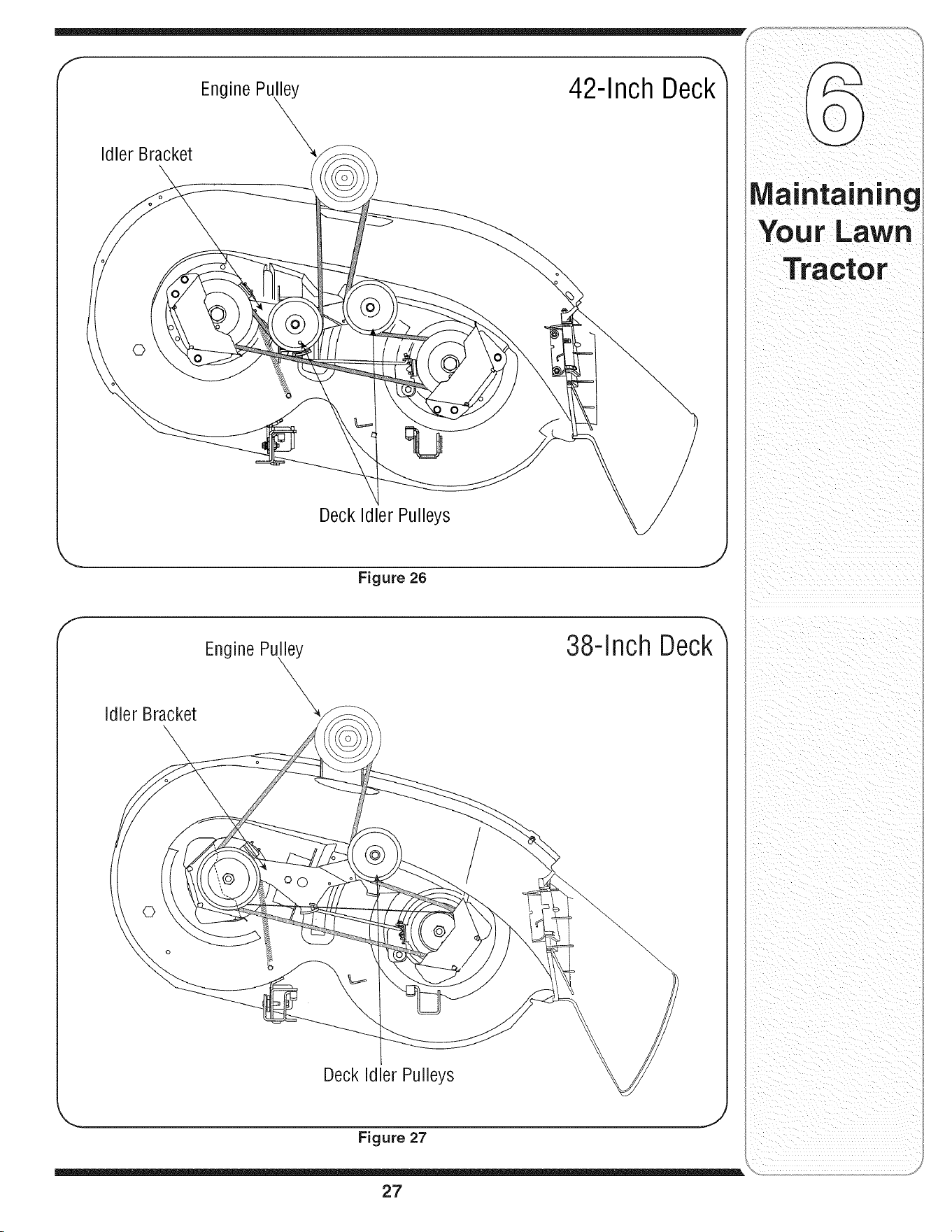
IdlerBracket
EnginePu_
42-Inch Deck_
©
Deck Idler Pulleys
.. j
Figure 26
f
Engine Pulley
38-Inch Deck_
Idler Bracket
©
Deck Idler Pulleys
Figure 27
Maintaining
Your Lawn
Tractor
27
WARNING
Drain fuel only into an
approvedcontainer
outdoors,away from
an open flame. Al-
low engine to cool
Extinguishcigarettes,
cigars, pipes, and
other sources of igni-
tion prior to draining
fuel.
Never store the ma-
chine or fuel container
indoors where there is
an open flame, spark
or pilot lightsuch
as on water heater,
furnace, clothes dryer
or other gas appliance.
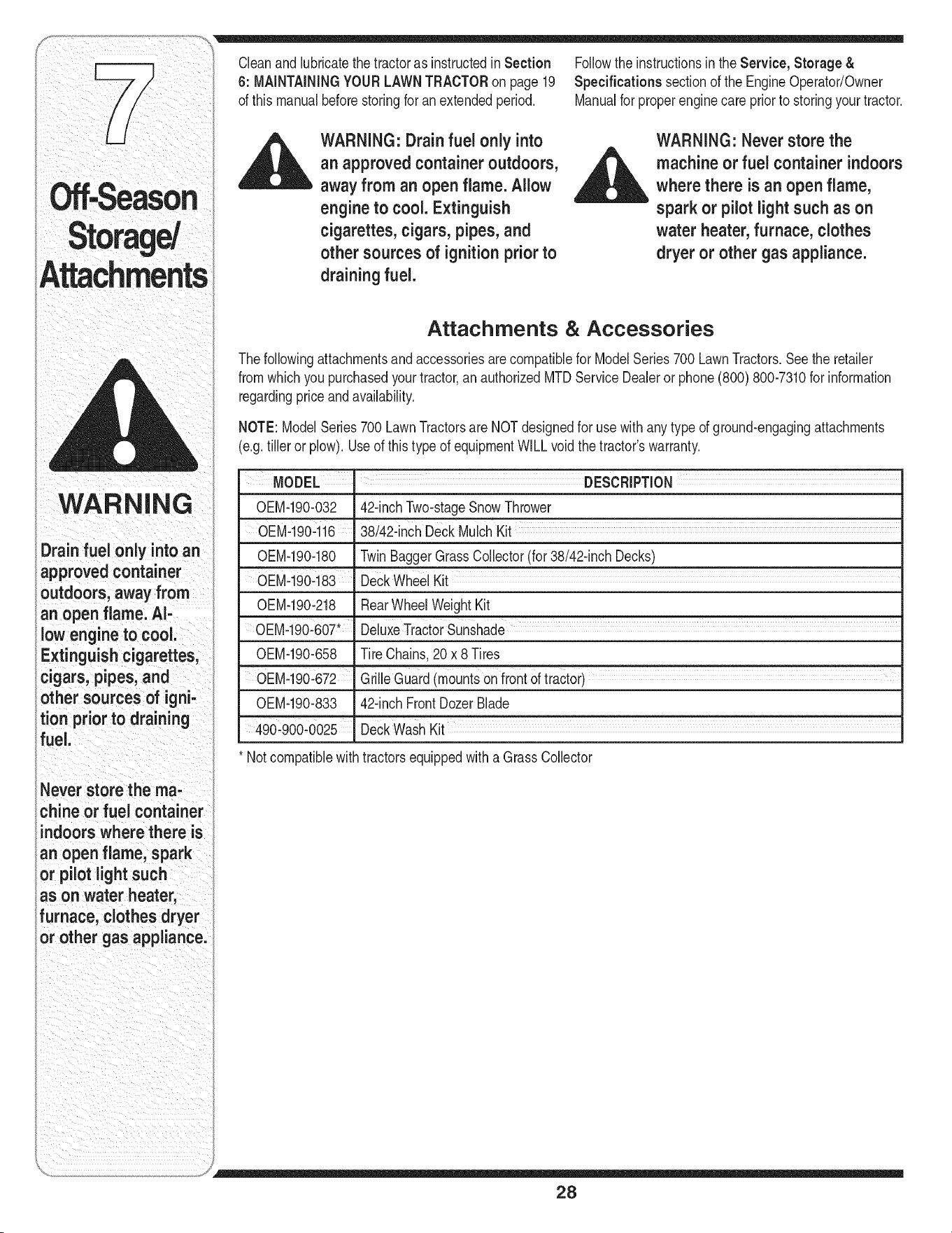
Cleanandlubricatethe tractoras instructedinSection
6: MAiNTAiNiNGYOUR LAWNTRACTORon page19
of thismanualbeforestoringfor an extendedperiod.
_ ARNING" Drain fuel only into
an approved containeroutdoors,
away from an open flame. Allow
engine to cool. Extinguish
cigarettes, cigars, pipes, and
other sources of ignition prior to
draining fuel.
Followthe instructionsinthe Service, Storage &
Specifications sectionof the EngineOperator/Owner
Manualfor properenginecare priorto storingyourtractor.
WARNING: Never store the
__ achine or fuel container indoors
where there is an open flame,
spark or pilot light such as on
water heater, furnace, clothes
dryer or other gas appliance.
Attachments & Accessories
Thefollowingattachmentsand accessoriesare compatiblefor ModelSeries700 LawnTractors.See the retailer
fromwhichyou purchasedyourtractor,an authorizedMTDServiceDealeror phone(800) 800-7310for information
regardingpriceandavailability.
NOTE:ModelSeries700 LawnTractorsare NOTdesignedfor usewithany typeof ground-engagingattachments
(e.g.tiller or plow). Useof this type of equipmentWILLvoidthe tractor'swarranty.
MODEL I DESCRiPTiON
0EM-190-032 42-inchTwo-stageSnowThrower
OEM-190416 ....38/42-inchDeckMulchKit
0EM-190-180 TwinBaggerGrassCollector(for 38/42-inchDecks)
0EM-190-183' DeckWheelKit
0EM-190-218 RearWheelWeightKit
OEM-190-607' DeluxeTract0rsUnshade
OEM-190-658 Tire Chains,20x 8 Tires
OEM-190:672 GrilleGUard(mountsonfrontoftractor)
OEM-190-833 42-inchFrontDozerBlade
490_900-0025 "Deck WashKit
* Notcompatiblewith tractorsequippedwith a GrassCollector
28
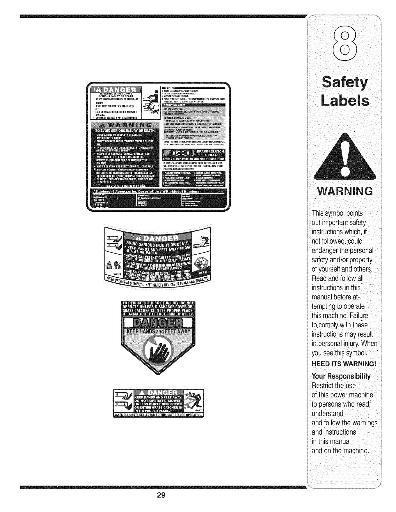
NOTE:i. eOTHMODES,WHENOP_e_TO_LeavesSEAT,e_GINeWlL_
STOP_NLES__R_I_QeP_KEISSETANDe_ossme_ISEN_ED.
IF UNIT STALLS W]TH SPEED CONTROL IN HIGH SPEED, OR IF UNIT
WILL NOT OPERATE WITH SPEED CONTROL LEVER IN _ LOW SPEED
POSITION, PROCEED _S FOLLOWS:
ASSEMBLE CHUTE DEFLECTOR TO THIS UNIT BEFOREOPERATING.
29
WARNING
This symbolpoints
out importantsafety
instructionswhich, if
not followed,could
endangerthe personal
safety and/or property
of yourselfand others.
Readand follow all
instructionsin this
manual beforeat-
temptingto operate
this machine. Failure
to comply with these
instructionsmay result
in personalinjury.When
you see this symbol.
HEED ITS WARNING!
Your Responsibility
Restrictthe use
of this power machine
to persons who read,
understand
and follow the warnings
and instructions
in this manual
and onthe machine.
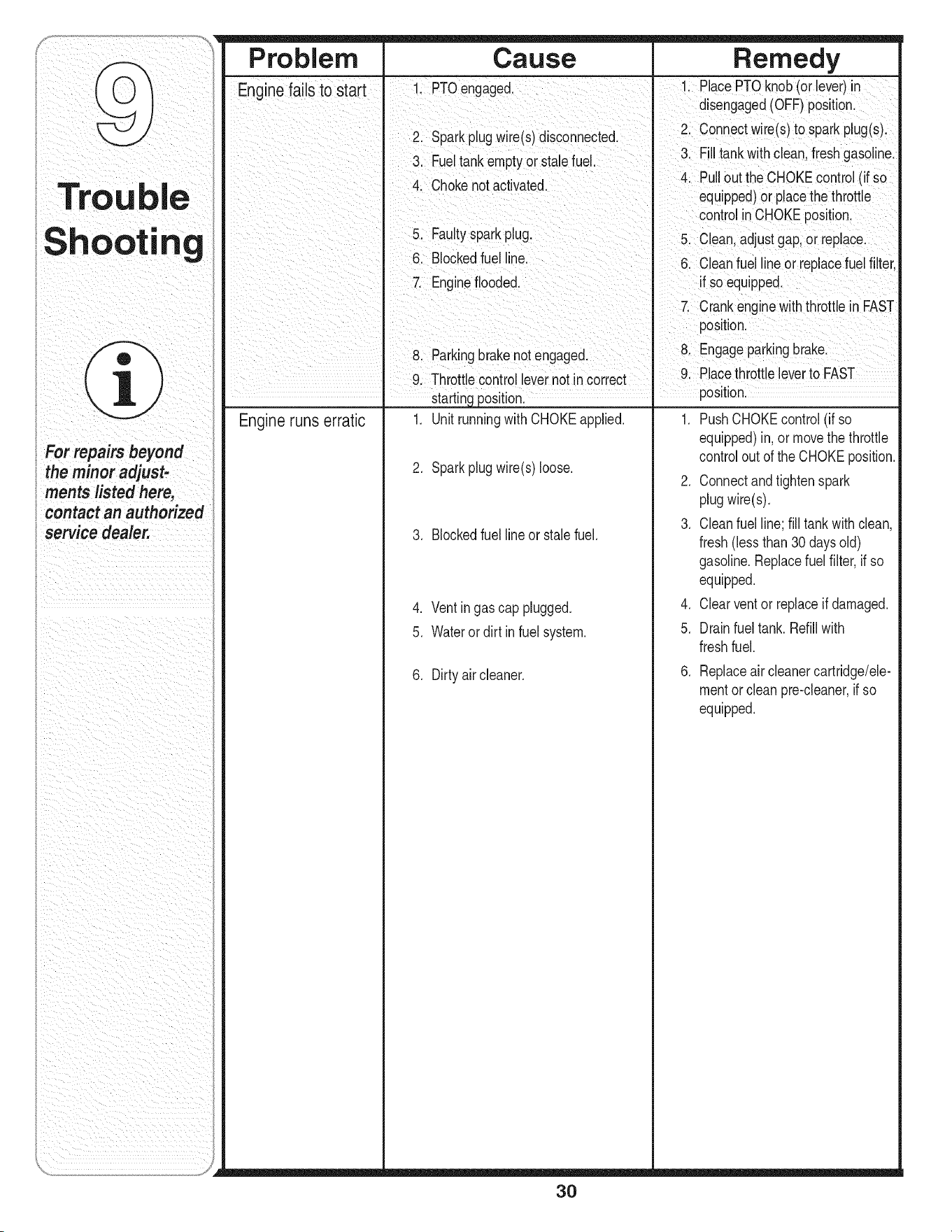
Trou
Shootin
e
For repairs beyond
the minor adjust-
ments listed here,
contact an authorized
service dealer.
Pro bl e m Ca use Remedy
Enginefails to start I 1 PTOengaged. 1 PlacePTOknob(orlever)in
I disengaged(OFF)position.
I 2. Sparkplugw re(s)disconnected. 2. Connectwire(s) to spark plug(s).
3 Fueltank em t or stalefuel 3 F tankwth c ean fresh gaso ne
py . •
I 4 Chokenot actvated 4. Pullout the CHOKEcontrol (if so
I " ' equipped)orplacethe throttle
I controlinCHOKEposition.
I 5. Faultysparkplug, 5. Clean,adjustgap,or replace
I 6. Blockedfuel line. 6. Cleanfuel lineor replacefuelfilter,
I 7. Engineflooded, if so equipped.
I I 7 Crankenginewiththrott e n FAST
I position.
I 8 Parkng brakenotengaged I 8. Engageparkingbrake.
I 9. Throttlecontro levernotin correct , 9. Placethrottleleverto FAST
I startingposition. _ position.
Engineruns erratic 1, Unit runningwith CHOKEapplied, 1, PushCHOKEcontrol(if so
2, Sparkplugwire(s)loose,
3, Blockedfuellineor stale fuel,
4, Ventingas cap plugged,
5, Waterordirt infuel system,
6. Dirty aircleaner.
_ J _ =_
30
equipped)in,or movethe throttle
controlout of the CHOKEposition.
2. Connectandtightenspark
plugwire(s).
3. Cleanfuel line;fill tank with clean,
fresh(lessthan30 daysold)
gasoline.Replacefuel filter,ifso
equipped.
4. Clearventor replaceif damaged.
5. Drainfuel tank. Refillwith
freshfuel.
6. Replaceair cleanercartridge/ele-
mentor cleanpre-cleaner,if so
equipped.
_ i
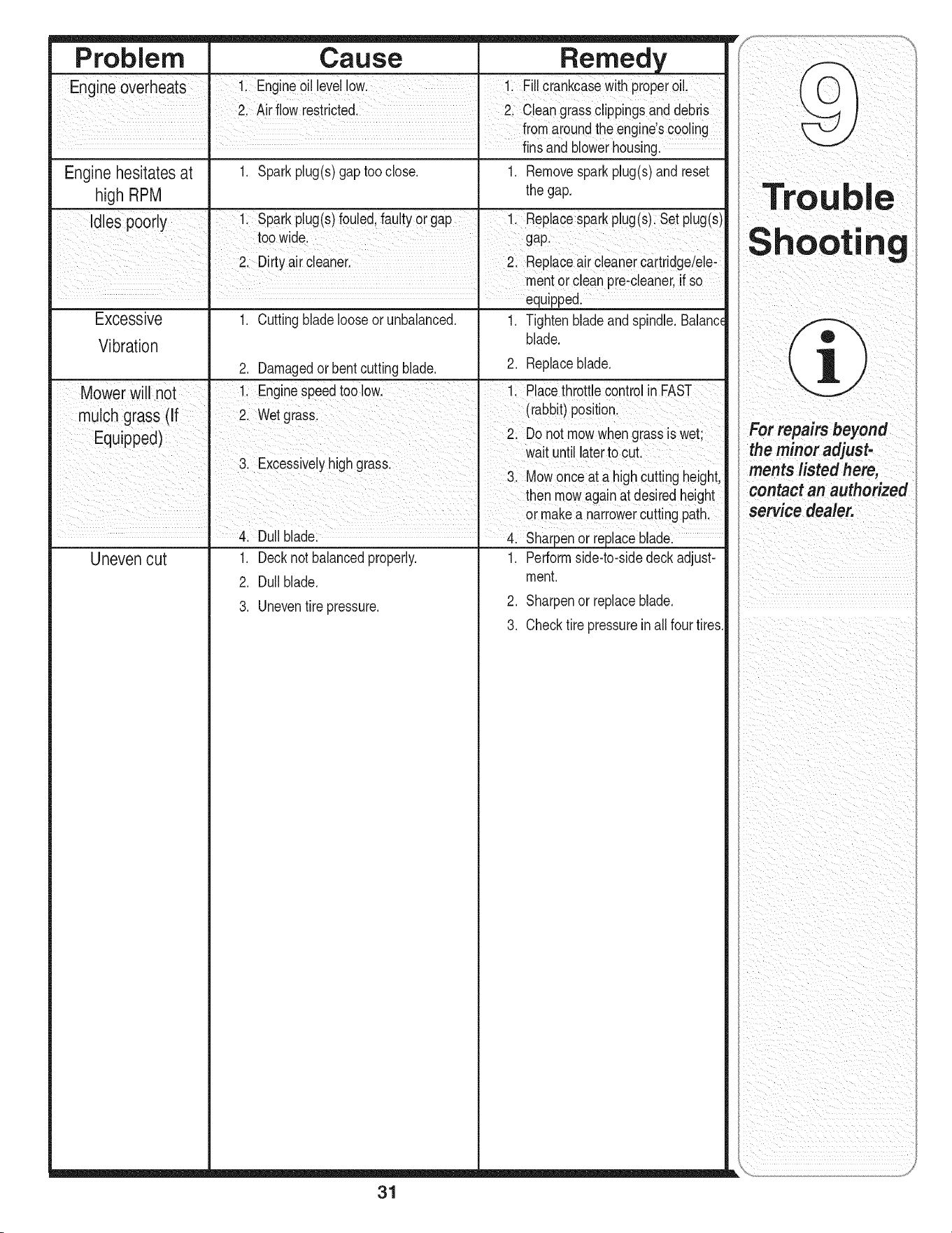
Problem Cause Remedy
Engineoverheats !i Engine Oi!levellow. !i Fi!!Ciankcasewith pr0pero!!,
21Air flow restricted. 2 c eangrass clippingsand debiis
fromaroundthe engines €00!ing
..... finsandblowerhousing.
Enginehesitates at 1. Sparkplug(s)gaptooclose, 1, Removesparkplug(s)and reset
high RPM the gap,
Idles poorl 1 Sparkpug(s)foued fautyorgap 1 Repacesparkpug(s)Setpug(s)
y ' ' t
too wide_ gap:
2 Dirtyair €eaner Replaceair cleanercaitr dgdele:
mentor cleanpre:cleaner if So
equipped.
Excessive 1. Cuttingbladelooseorunbalanced. 1. Tightenbladeandspindle. Balanc_
Vibration blade.
2. Damagedor bentcuttingblade. 2. Replaceblade.
Mower will not 11 Enginespeedtoo iowl 1; P!acethrott!e €ontrolin FAST
ohgrass (If wet grass (rabbit)p0siti°n.
Equipped) 2. Donot m0wwhengrass s wet
wat unt aterto cut
3. Excessivelyhigh grassl ,,,
_. Mowonce a! a nigncuttingneight,
then mowagainat desiredheight
or makea narrowerCuttingpath,
Duiiblade &sharpen or repiacebiade:
Uneven cut 1. Decknotbalancedproperly. 1. Performside-to-sidedeck adjust-
2. Dullblade, ment.
2. Sharpenor replaceblade.
3. Uneventire pressure.
3. Checktire pressureinall fourtires.
rou
31

Use this page to make
notes and write down
important information:
32

33
U_e_¸pagetoma_
notesandwritedown
important information:
i

i_il i_i i i _II _i _ i _ i i ii
,i!_ii_i_i!i_ii_ii_!_i_i_ii_i_i_i_i_i_i_i_i_i_i_i_i_i_i_i_i_I
34
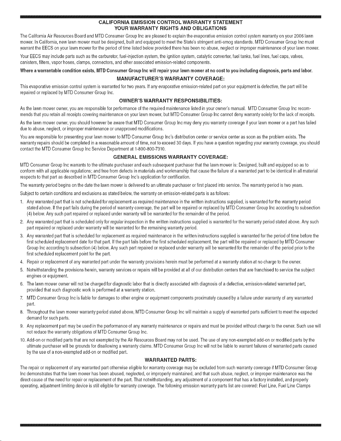
CALIFORNIA EMISSION CONTROL WARRANTY STATEMENT
YOUR WARRANTY RIGHTS AND OBLIGATIONS
The CaliforniaAir ResourcesBoardandMTDConsumerGroupInc are pleasedto explaintheevaporativeemissioncontrolsystemwarrantyon your 2006 lawn
mower.In California,new lawnmowermust be designed,builtand equippedto meet the State'sstringentanti-smogstandards.MTDConsumerGroup Inc must
warrantthe EECSon yourlawn mowerfor the periodof time listedbelow providedthere has beenno abuse,neglector impropermaintenanceof your lawnmower.
Your EECSmayincludeparts such as thecarburetor,fuel-injectionsystem,the ignitionsystem,catalyticconverter,fuel tanks,fuel lines,fuel caps, valves,
canisters,filters,vapor hoses,clamps,connectors,and otherassociatedemission-relatedcomponents.
Where a warrantable condition exists, MTDConsumer Group Inc will repair your lawn mower at no cost to you includingdiagnosis, parts and labor.
MANUFACTURER'S WARRANTY COVERAGE:
Thisevaporativeemissioncontrol systemis warrantedfor two years.If any evaporativeemission-relatedpart on yourequipmentis defective,the partwill be
repairedor replacedby MTDConsumerGroupInc.
OWNER'S WARRANTY RESPONSIBILITIES:
Asthe lawn mowerowner,you are responsiblefor performanceof the requiredmaintenancelistedin yourowner'smanual. MTDConsumerGroupIncrecom-
mendsthat you retain all receiptscoveringmaintenanceon your lawnmower,but MTDConsumerGroup Inccannot denywarrantysolelyforthe lack of receipts.
Asthe lawn mowerowner,you shouldhoweverbeawarethat MTDConsumerGroupInc maydeny you warrantycoverageif your lawnmoweror a part has failed
dueto abuse,neglect, or impropermaintenanceor unapprovedmodifications.
Youare responsiblefor presentingyourlawn mowerto MTDConsumerGroupInc'sdistributioncenteror servicecenteras soonas the problemexists.The
warrantyrepairsshouldbe completedin a reasonableamountof time, notto exceed30 days.If you havea questionregardingyour warrantycoverage,you should
contactthe MTDConsumerGroupIncService Departmentat 1-800-800-7310.
GENERAL EMISSIONS WARRANTY COVERAGE:
MTDConsumerGroupIncwarrantsto the ultimatepurchaserand eachsubsequentpurchaserthat the lawnmoweris: Designed,built andequippedso as to
conformwithall applicableregulations;andfree from defectsin materialsand workmanshipthat causethe failure of a warrantedpart to be identicalin allmaterial
respectsto that part as describedin MTDConsumerGroupInc's applicationfor certification.
The warrantyperiodbeginson thedate the lawnmoweris deliveredto an ultimatepurchaseror first placed into service.The warrantyperiodis two years.
Subjectto certain conditionsand exclusionsas statedbelow,the warrantyon emission-relatedparts is as follows:
1. Any warrantedpart that is not scheduledfor replacementas requiredmaintenanceinthe writteninstructionssupplied,is warrantedfor thewarrantyperiod
statedabove. Ifthe part fails duringthe periodof warrantycoverage,the part will be repairedor replacedby MTDConsumerGroupInc accordingto subsection
(4) below. Anysuch part repairedor replacedunderwarrantywillbe warrantedfor the remainderof the period.
2. Any warrantedpart that is scheduledonly for regularinspection inthe writteninstructionssupplied is warrantedfor thewarranty periodstated above.Any such
part repairedor replacedunderwarrantywill be warrantedfor the remainingwarrantyperiod.
3. Any warrantedpart that is scheduledfor replacementas requiredmaintenancein thewritten instructionssuppliedis warrantedforthe periodof time beforethe
first scheduledreplacementdatefor that part. If the partfails beforethe first scheduledreplacement,the part will be repairedor replacedby MTDConsumer
GroupInc accordingto subsection(4) below.Any such part repairedor replacedunderwarrantywillbe warrantedforthe remainderof the periodpriorto the
first scheduledreplacementpointfor the part.
4. Repairor replacementof any warrantedpart underthe warrantyprovisionshereinmustbe performedat a warrantystationat no chargeto the owner.
5. Notwithstandingthe provisionsherein,warrantyservicesor repairswill be providedat all of our distributioncentersthat arefranchisedto servicethe subject
enginesor equipment.
6. The lawnmowerowner will not be chargedfor diagnosticlaborthat is directlyassociatedwithdiagnosisof a defective,emission-relatedwarrantedpart,
providedthat such diagnosticwork is performedat a warrantystation.
7. MTDConsumerGroupInc is liablefor damagesto other engine or equipmentcomponentsproximatelycausedby a failure underwarrantyof any warranted
part.
8. Throughoutthe lawnmowerwarrantyperiod stated above,MTDConsumerGroupIncwill maintaina supplyof warrantedparts sufficientto meetthe expected
demandfor such parts.
9. Any replacementpart may be usedin the performanceof any warrantymaintenanceor repairsand mustbe providedwithoutchargeto the owner.Suchuse will
notreducethe warrantyobligationsof MTDConsumerGroupInc.
10.Add-onor modifiedpartsthat are not exemptedbythe Air ResourcesBoardmay not beused.The use of any non-exemptedadd-on or modifiedparts by the
ultimatepurchaserwillbe groundsfor disallowinga warrantyclaims. MTDConsumerGroup Incwill notbe liableto warrantfailuresof warrantedparts caused
bythe useof a non-exemptedadd-onor modifiedpart.
WARRANTED PARTS:
The repairor replacementof any warrantedpart otherwiseeligiblefor warrantycoveragemaybe excludedfrom such warrantycoverageif MTDConsumerGroup
Inc demonstratesthat the lawnmowerhas been abused,neglected,or improperlymaintained,andthat such abuse, neglect,or impropermaintenancewasthe
directcauseof the needfor repairor replacementof the part.That notwithstanding,any adjustmentof a componentthathas a factory installed,and properly
operating,adjustmentlimiting device is still eligiblefor warrantycoverage.Thefollowingemissionwarrantyparts list arecovered: FuelLine,Fuel Line Clamps

MANUFACTURER'S LiMiTED WARRANTY FOR
The limitedwarrantysetforthbelowisgivenby MTDLLCwithrespect
to newmerchandisepurchasedandusedin the UnitedStates,its
possessionsandterritories.
"MTD"warrantsthisproductagainstdefectsinmaterialand workman-
shipfor a periodof two (2)years commencingonthe date of original
purchaseandwill,at itsoption,repairor replace,freeof charge,any
part foundto be defectiveinmaterialsorworkmanship.Thislimitedwar-
rantyshallonlyapply if this product hasbeen operatedand maintained
inaccordancewith the Operator'sManualfurnishedwiththe product,
andhas notbeensubjectto misuse,abuse,commercialuse, neglect,
accident,impropermaintenance,alteration,vandalism,theft, fire, water,
ordamagebecauseof otherperilor naturaldisaster.Damageresulting
fromthe installationor useof any part, accessoryor attachmentnot
approvedby MTDfor use with the product(s)coveredbythis manual
willvoid yourwarrantyas to any resultingdamage.
Normalwearpartsarewarrantedto be free fromdefects in materialand
workmanshipfor a periodof thirty (30) days fromthe dateof purchase.
Normalwearpartsinclude,butare notlimitedto itemssuch as: batter-
ies,belts,blades,bladeadapters,grassbags,riderdeckwheels,seats,
snowthrowerskidshoes,shaveplates,auger spiralrubberandtires.
NOW TO OBTAIN SERVICE: Warranty service is available,WITH
PROOFOF PURCHASE, through your local authorized service
dealer. To locate the dealer in your area, check your Yellow Pages,
or contact MTD LLC at RO. Box 361131,Cleveland, Ohio 44136-
0019, or call 1-800-800-7310or 1-330-220-4683 or log on to our
Web site at www.mtdproducts.com.
Thislimitedwarrantydoesnotprovidecoverageinthe followingcases:
a. Theengineor componentparts thereof.Theseitemsmaycarrya
separatemanufacturer'swarranty.Referto applicablemanufacturer's
warrantyfor termsandconditions.
b. Logsplitterpumps,valves,and cylindershavea separateoneyear
warranty.
c. Routinemaintenanceitemssuchas lubricants,filters, blade
sharpening,tune-ups,brakeadjustments,clutchadjustments,deck
adjustments,and normaldeteriorationof the exteriorfinishdueto
useor exposure.
d. Servicecompletedby someoneotherthananauthorizedservice
dealer.
e. MTDdoesnot extendanywarrantyfor productssoldor exported
outsideof the UnitedStates,its possessionsandterritories,except
thosesoldthroughMTD'sauthorizedchannelsof exportdistribution.
f. Replacementpartsthatarenotgenuine MTDparts.
g. Transportationchargesandservicecalls.
No impliedwarranty,includingany impliedwarrantyof mer-
chantabilityof fitness for a particular purpose,applies after the
applicable periodof express written warranty above as to the
partsas identified.No otherexpresswarranty, whetherwritten or
oral, except as mentioned above,givenby any personor entity,
includinga dealeror retailer, withrespect to any product,shall
bindMTD.Duringthe periodof the warranty,the exclusiveremedy
is repairor replacementof the productas set forth above.
Theprovisionsas set forth inthis warrantyprovidethe sole and
exclusiveremedy arising from the sale.MTDshallnot be liable
for incidentalor consequentialloss or damage including,without
limitation, expensesincurredfor substituteor replacementlawn
careservicesor for rentalexpensesto temporarily replacea
warranted product.
Somestatesdo notallowthe exclusionor limitationof incidentalor
consequentialdamages,or limitationsonhowlongan impliedwarranty
lasts,sothe aboveexclusionsor limitationsmaynot applyto you.
Innoeventshallrecoveryof any kindbe greaterthanthe amountof the
purchasepriceof the productsold.Alterationof safetyfeatures of
the product shallvoid this warranty. Youassumethe riskand liability
for loss,damage,or injuryto you and yourpropertyand/orto othersand
theirpropertyarisingout of the misuseor inabilityto usethe product.
Thislimitedwarrantyshallnot extendto anyoneotherthan theoriginal
purchaserorto the personfor whomitwas purchasedas a gift.
HOWSTATELAWRELATESTOTHIS WARRANTY: This limited
warrantygivesyou specificlegal rights,and youmay alsohaveother
rightswhichvaryfromstateto state.
IMPORTANT:OwnermustpresentOriginal Proofof Purchaseto obtain
warrantycoverage.
MTD LLC, P.O. BOX 361131 CLEVELAND, OHIO 44136=0019; Phone: 1=800=800=7310, 1=330=220=4683