Loading ...
Loading ...
Loading ...
ENGLISH
8
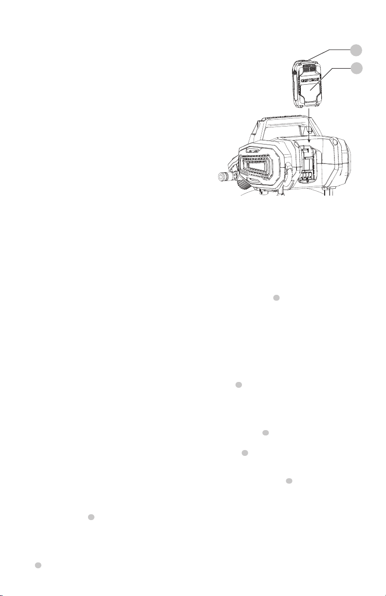
Installing and Removing the Battery Pack
(Fig. B)
NOTE: For best results, make sure your battery pack is
fullycharged.
To install the battery pack
2
into the tool handle, align the
battery pack with the rails inside the tool’s handle and slide
it into the handle until the battery pack is firmly seated in
the tool and ensure that it does notdisengage.
To remove the battery pack from the tool, press the release
button
3
and firmly pull the battery pack out of the tool
OPERATION
WARNING: To reduce the risk of serious personal
injury, turn unit off and remove the battery pack
before making any adjustments or removing/
installing attachments or accessories. An
accidental start-up can causeinjury.
How To Set Up Your Unit
Unpacking
Remove unit from carton and discard allpackaging.
Location of the Air Compressor
• Locate the air compressor in a clean, dry and well
ventilatedarea.
• The air compressor should be located at least 12"
(30.5 cm) away from the wall or other obstructions that
will interfere with the flow ofair.
• The air compressor pump and shroud are designed
to allow for proper cooling. The ventilation openings
on the compressor are necessary to maintain proper
operating temperature. Do not place rags or other
containers on or near theseopenings.
Intended Use
Your compressor is designed for residential finish nailing
and staplingapplications.
DO NOT use under wet conditions or in presence of
flammable liquids orgases.
DO NOT let children come into contact with the tool.
Supervision is required when inexperienced operators use
thistool.
ASSEMBLY AND ADJUSTMENTS
WARNING: To reduce the risk of serious personal
injury, turn unit off and remove the battery pack
before making any adjustments or removing/
installing attachments or accessories. An
accidental start-up can causeinjury.
screw exposed. Align the slots on the back of the charger
with the exposed screws and fully engage them in theslots.
Versatrack™
CRAFTSMAN chargers can be mounted to the wall using
CRAFTSMAN Versatrack™ Trackwall. Hooks and accessories
are sold separately. Please refer to the Versatrack™ Trackwall
accessory sheet for furtherinformation.
Know Your Air Compressor
READ THIS OWNER’S MANUAL AND SAFETY RULES BEFORE
OPERATING YOUR UNIT. Compare the illustrations with
your unit to familiarize yourself with the location of
various controls and adjustments. Save this manual for
futurereference.
Description of Operation (Fig. A)
Become familiar with these controls before operating
theunit.
Auto On(I)/Off(O) Switch
1
: Place this switch in the
"AutoOn" position to provide automatic power to the
pressure switch and "Off" to remove power at the end of
eachuse.
Pressure Switch (not shown): The pressure switch
automatically starts the motor when the air tank pressure
drops below the factory set "cut-in" pressure. It stops the
motor when the air tank pressure reaches the factory set
"cut-out"pressure.
Safety Valve
4
: If the pressure switch does not shut off the
air compressor at its "cut-out" pressure setting, the safety
valve will protect against high pressure by "popping out"
at its factory set pressure (slightly higher than the pressure
switch "cut-out"setting).
Tank Pressure Gauge
5
: The tank pressure gauge
indicates the reserve air pressure in thetank.
Regulator Dial
7
: Controls the air pressure available at the
quick-connect outlet. Turn regulator clockwise to increase
pressure or counterclockwise to decrease pressure. Stop
when regulator pressure gauge
6
matches with desired
outlet pressure.
Cooling System (not shown): This compressor contains
an advanced design cooling system. At the heart of this
cooling system is an engineered fan. It is perfectly normal
for this fan to blow air through the vent holes in large
amounts. You know that the cooling system is working
when air is beingexpelled.
Air Compressor Pump (not shown): Compresses air into
the air tank. Working air is not available until the compressor
handle. Insert it into the charger as described in the charger
section of thismanual.
Fig.B
3
2
Loading ...
Loading ...
Loading ...