Loading ...
Loading ...
Loading ...
 
 
        
     
      
      
     
    
       
 
   
      
     
      
   
!  " #$
%      


%       
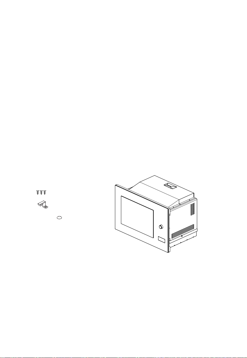
Installation Instructions
Please Read the Manual Carefully Before Installation
A gap must be maintained between
the wall and the base of the
unit above.
Specific
gap size
could be referenced by the diagrams.
Screw
Trim
-kit
pl
asti
c
co
ve
r
Mounting Plate
12
Loading ...
Loading ...
Loading ...