Save This Manual
For Future Reference
SEARS
Operators
Manual
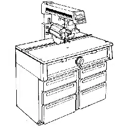
MODEL NO.
113.198411
10" DELUXE ELECTRONIC
RADIAL SAW WITH
44" CABINET AND
2 DOORS
or
113.198611
10" DELUXE ELECTRONIC
RADIAL SAW WITH
44" CABINET AND
6 DRAWERS
Serial
Number
Model and serial numbers
may be found at the rear of
the base,
You should record both
model and serial number in
a safe place for future use.
CAUTION:
READ ALL
INSTRUCTIONS
CAREFULLY
\
MODEL 113.198611
MODEL 113.198411
CRRFTSMRN
10-INCH DELUXE ELECTRONIC
RADIAL SAW
• Assembly
• Operating
• Repair parts
Sold by SEARS, ROEBUCK AND CO., Chicago, IL. 60684 U.S.A.
Part No. SP5105 Printed in U.S.A.
FULL ONE YEAR WARRANTY ON CRAFTSMAN RADIAL SAW
If within one year from the date of purchase, this Craftsman Radial Saw fails due to a defect in material or
workmanship, Sears will repair it, free of charge.
WARRANTY SERVICE IS AVAILABLE BY SIMPLY CONTACTING THE NEAREST SEARS SERVICE
CENTER/DEPARTMENT THROUGHOUT THE UNITED STATES.
This warranty applies only while this product is used in the United States.
This warranty gives you specific legal rights and you may also have other rights which vary from slate to state.
SEARS, ROEBUCK AND CO., DEPT. 698/731A Sears Tower, Chicago, IL 60684
_a
i i
Table of Contents
SectionTitle Page Numbers
Safety Information ............................................................................................ 3-6
Putting Your Saw Together .......................................................................... 7-30
Location and Function of Controls ........................................................... 31-34
Alignment of the Blade ............................................................................... 35-49
Digital Display .............................................................................................. 50-55
Electrical Connections ................................................................................ 56-57
Crosscutting ................................................................................................... 58-64
Ripping ........................................................................................................... 65-73
Cutting Accessories ...................................................................................... 74-77
Recommended Accessories .............................................................................. 78
Glossary ............................................................................................................... .79
Helpful Hints ................................................................................................ 80-81
Maintaining Your Saw ................................................................................. 82-88
Changing Motor Voltage .................................................................................. 89
Trouble Shooting .......................................................................................... 90-95
Parts Lists .................................................................................................... 96-114
Safety Information
The operator's manual contains safety infor-
marion, instructions and signs for your protec-
tion against serious injuries, including:
Loss of fingers, hand, arm or leg from contact
with the saw blade.
Eye injuries, including being blinded from
being hit by a thrown workpiece, workpiece
chips or pieces of the saw blade.
Impact injuries, including broken bones and
internal organ damage, from being hit by a
thrown workpiece, workpiece chips or pieces
of the saw blade.
Shock, electrocution, or burn injuries from
contact with wires, motor or other saw parts.
Safety Symbol and Signal Words
The safety information in this manual is high-
lighted by the following safety alert symbol.
Fig. 1Safety Alert Symbol
The following signal words are used to indi-
cate the level of risk.
DANGER: Means that if the safety infor-
mation is not followed, someone will be
seriously injured or killed.
WARNING: Means that if the safety in-
formation is not followed someone could be
seriously injured or killed.
CAUTION: Means that if the safety in-
formation is not followed someone may be in-
jured.
All of the safety information and cutting
steps are critical to the safe operation of the
radial arm saw.
Major Hazards
1. Workpiece Kickback
Kickback is an uncontrolled grabbing and
throwing of the workpiece during ripping. If
kickback occurs, the workpiece can hit
you hard enough to cause broken bones, in-
ternal organ injury or death. To reduce or
prevent kickback, read and follow the safety
information in the Ripping section of the
manual.
Kickback.
Internal injury can
result.
Use anti-kickback
pawls/spreader.
Fig. 2 Kickback Safely Sign
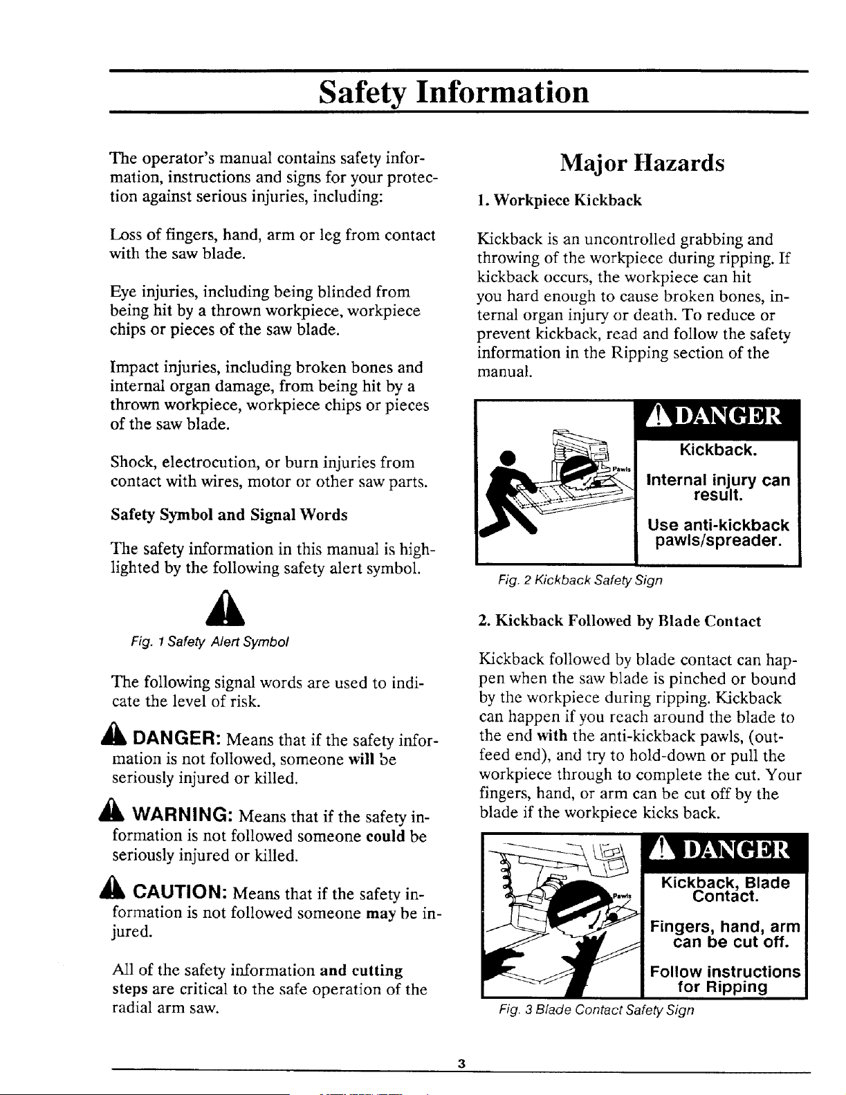
2. Kickback Followed by Blade Contact
Kickback followed by blade contact can hap-
pen when the saw blade is pinched or bound
by the workpiece during ripping. Kickback
can happen if you reach around the blade to
the end with the anti-kickback pawls, (out-
feed end), and try to hold-down or pull the
workpiece through to complete the cut. Your
fingers, hand, or arm can be cut off by the
blade if the workpiece kicks back.
Kickback, Blade
Contact.
Fingers, hand, arm
can be cut off.
Follow instructions
for Ripping
Fig. 3 Blade Contact Safely Sign
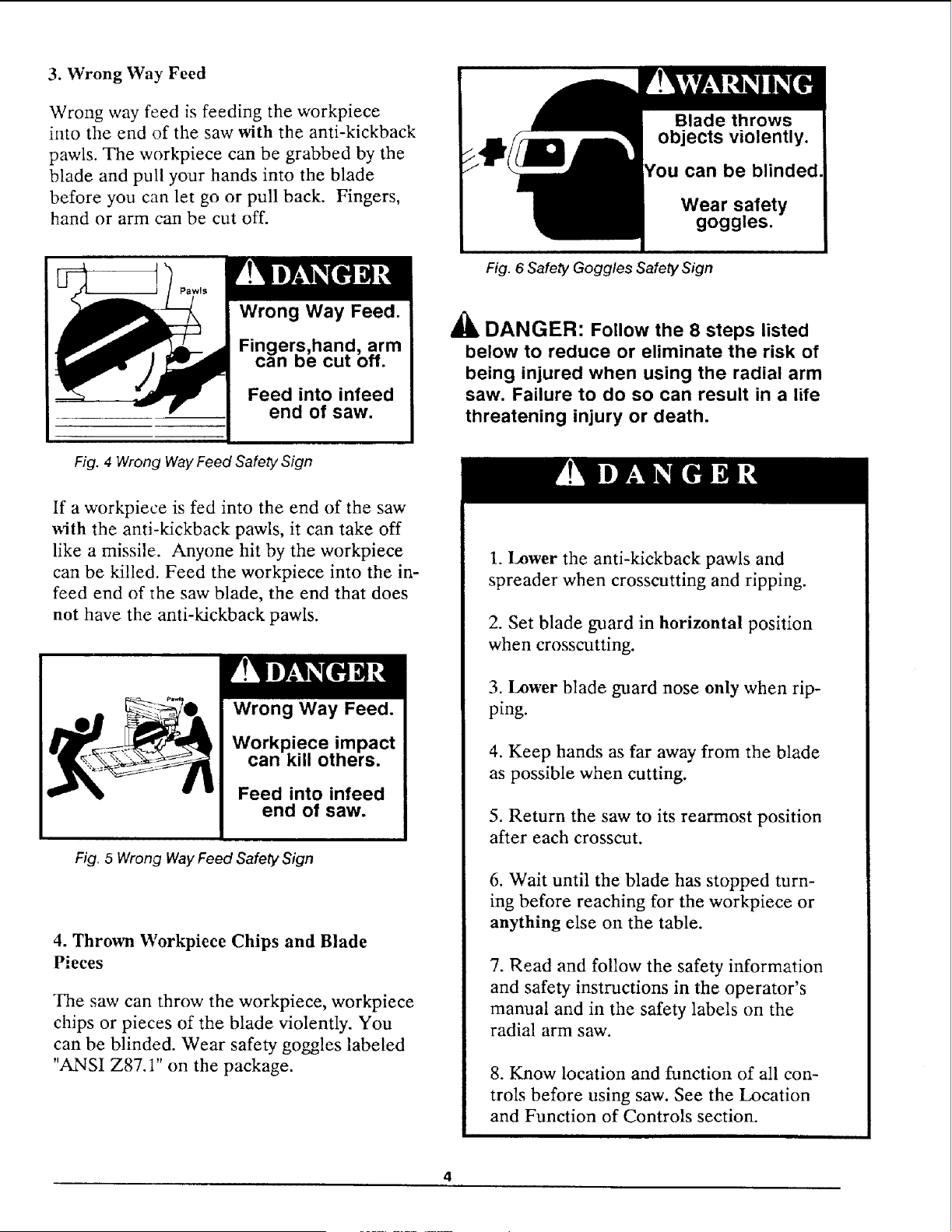
3. Wrong Way Feed
Wrong way feed is feeding the workpiece
into the end of the saw with the anti-kickback
pawls. The workpiece can be grabbed by the
blade and pull your hands into the blade
before you can let go or pull back. Fingers,
hand or arm can be cut off.
can be blinded.
Wear safety
goggles.
Wrong Way Feed.
Fingers,ban.d, arm
can De cut on.
Feed into infeed
end of saw.
Fig. 6 Safety Goggles Safety Sign
_lb DANGER: Follow the 8 steps listed
below to reduce or eliminate the risk of
being injured when using the radial arm
saw. Failure to do so can result in a life
threatening injury or death.
Fig. 4 Wrong Way Feed Safety Sign
If a workpiece is fed into the end of the saw
with the anti-kickback pawls, it can take off
like a missile. Anyone hit by the workpiece
can be killed. Feed the workpiece into the in-
feed end of the saw blade, the end that does
not have the anti-kickback pawls.
Wrong Way Feed.
Workpiece impact
can kill others.
Feed into infeed
end of saw.
Fig. 5 Wrong Way Feed Safety Sign
4. Thrown Workpiece Chips and Blade
Pieces
The saw can throw the workpiece, workpiece
chips or pieces of the blade violently. You
can be blinded. Wear safety goggles labeled
"ANSI Z87.1" on the package.
1. Lower the anti-kickback pawls and
spreader when crosscutting and ripping.
2. Set blade guard in horizontal position
when crosscutting.
3. Lower blade guard nose only when rip-
ping.
4. Keep hands as far away from the blade
as possible when cutting.
5. Return the saw to its rearmost position
after each crosscut.
6. Wait until the blade has stopped turn-
ing before reaching for the workpiece or
anything else on the table.
7. Read and follow the safety information
and safety instructions in the operator's
manual and in the safety labels on the
radial arm saw.
8. Know location and function of all con-
trois before using saw. See the Location
and Function of Controls section.

Personal Safety
1. Wear safety goggles labeled "ANSI Z87.1"
on the package. Do not wear regular glasses,
they are not safety glasses.
2. Wear snug fitting clothes, short sleeve
shirts and nonslip footwear. Cover up or tie
long hair. Do not wear loose, baggy clothes,
gleves, neckties, rings, watches or any other
:jewelry.
3. Wear a dust mask, with your safety gog-
gles, if cutting operation is dusty.
4. Wear hearing protectors, ear plugs or
muffs, if you use the saw daily.
5. Keep good footing and balance. Don't over-
reach.
Work Area Safety
1. Keep children, pets and visitors out of the
work area.
2. Make the work area child proof. Remove
the yellow key from the red switch and place
it out of reach and sight. Lock work area.
3. Keep floors dry and free from sawdust, wax
or other slippeu materials.
4. Keep work area clean, uncluttered and
well lighted.
5. Use the saw in a dr), area. Do not use in
wet or damp area. Do not use outside.
6. Clear the table of all ebjects (adjusting
wrenches, tools, scraps of wood etc.) except
the workpiece to be cut, fixtures or clamps
before turning the saw on.
7. Do not do layout, assembly or setup work
on the table while the blade is turning.
8. Store items away from the saw. Do not
climb on the saw to reach items. Do not
stand on the table; the saw can tip over.
Saw Safety
1. Keep guards and anti-kickback pawls in
place and in working order.
2. Check for broken or damaged parts before
using saw. A damaged guard or other saw
part should be checked for alignment, bind-
ing, breakage and correct mounting to make
sure they are working properly. Repair or
replace damaged guards or other saw parts.
3. Unplug saw before doing maintenance,
making adjustments, and changing blades and
accessories.
4. Use clamps or vice to hold workpiece
when practical. It's safer than using your
hands and frees them to operate the saw.
5. Do not force the saw, saw blade or acces-
sories to do jobs they are not designed to do.
6. Make sure the yellow key is removed and
the red switch is in the off position before
plugging in the power cord.
7. Cut only wood, woodlike or plastic
materials. Do not cut metal materials.
8. Secure the saw to floor, wall, bench or
table if it slides, tips or walks during use.
9. Feed the workpiece against the direction
of rotation of the blade when ripping.
10. Turn the saw off before leaving work
area. Do not leave the saw until the blade
has stopped.
11. Lock the rip and miter locks before
moving the saw from one location to another.
12. Turn the saw off and remove yellow key if
the blade jams. Do not try to free a jammed
workpiece with the saw on.
13. Turn the saw off if it vibrates excessively
or makes an unfamiliar noise. Correct any
problems before restarting saw.
14.Rip workpieces that are longer than the
diameter of the blade being used.Do not rip
aworkpiece that is shorter than the diameter
of the blade being used.
15.Cut only one workpiece at a time. Do
not cut stackedworkpieces or lay them edge
to edge for cutting.
Workpiece Support Safety
1. Use additional supports for workpieces
which extend beyond the saw table. Large
workpieces can shift, twist, rise from table or
fall after they are cut.
2. Helpers can be hit by a thrown workpiece,
workpiece chips or pieces of the blade. Use
table extensions or other supports. Do not
use helpers.
3. Helpers can cause the workpiece to kick-
back. Do not use other people to support or
assist in feeding or pulling the workpiece.
Use table extensions. See Recommended Ac-
cessories section of the manual.
4. When table extensions over 24 inches wide
are added to either side of the saw, make
sure you either bolt the saw to the floor or
support the outer end of the extension from
the floor with sturdy legs or an outrigger.
Blade Safety
1. Use blades marked for 3450 rpm or higher.
2. Do not use blades larger than 10 inches in
diameter.
3. Keep blade sharp and clean.
4. Do not cycle motor switch on and off rapid-
ly; the blade can loosen.
5. Do not overtighten the blade; the blade
collar can be warped.
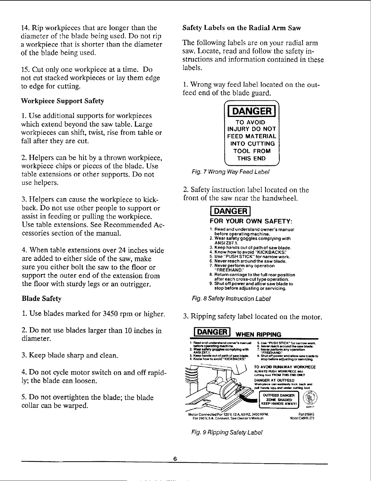
Safety Labels on the Radial Arm Saw
The following labels are on your radial arm
saw. Locate, read and follow the safety in-
structions and information contained in these
labels.
1. Wrong way feed label located on the out-
feed end of the blade guard.
I DANGER I
TO AVOID
INJURY DO NOT
FEED MATERIAL
INTO CUTTING
TOOL FROM
THIS END
Fig. 7 Wrong Way Feed Labe/
2. Safety instruction label located on the
front of the saw near the handwheel.
[ DANGER I
FOR YOUR OWN SAFETY:
t. Read and understand owner's manual
before operating machine.
2. Wear safety goggles complying with
ANSI Z87,1.
3. Keep hands out of path of saw blade.
4. Know how to avoid "KICKBACKS:'
5. Use "PUSH STICK" for narrow work,
6, Never reach around the saw blade.
7. Never perform any operation
"FREEHAND:'
8. Return carriage to the full rear position
after each cross-cut type operation.
9. Shut off power and allow saw blade to
stop before adjusting or servicing.
Fig. 8 Safety Instruction Label
3. Ripping safety label located on the motor.
I DANGER J WHEN RIPPING
1. R4HId =nd undlrltlnd OW._,eCS n_l_ ugl 5. UI_ "PUSH s'ncK" for narrow work.
before ng m.aehlne.
7_ NeVK rm any operatlo_
ANS_ Z87.r. "FRIErH_A_, "
3, Klmp hands out of path of imw binde. 8. Shut off power ar)d allow saw binde to
l, Know how to avoid "KICK BACKS;' stop before IKIJustir_j or _rvlclng.
cut_ t,o,_ _ THIS END ONLY
DANGER AT OUTFEED
pull han_l_ into and under _ t_
KEEP HANDS AWAY!
-- KIBEP HANDS AWAY! J _17
Motor Connected For 120 V,12 A, 60 HZ, 3450 RP M. Part816845
For 240 V, 6 A. Connect, See Own er's Manu_l. MOdel C48HX-273
Fig. 9 Ripping Safety Label
Putting Your Saw Together
,-..,
Your radial arm saw is easy to put together,
however it will take time. Ask a friend to
help, and follow these assembly instructions.
It is important for your safety, and for the
quality of your cuts, that the saw be put
together with care.
This manual was written for two different
models of the radial arm saw: model
113.198611 has drawers for the cabinet, and
model 113.198411 has doors.
The following assembly sections should be fol-
lowed for both models:
Unpacking / Set up
Information
Attaching Handwheel
Mounting Motor
Mounting Saw
Attaching Trim Ledge and Trim Caps
Mounting Table Locks
Mounting the Front Table
All other sections are labelled with the cor-
rect model number. Follow ONLY instruc-
tions that are meant for your model saw.
Both models work in the same way once they
are put together.
A
WARNING: Plugging the saw in
during assembly can result in electrical
shock or your fingers, hand, or arm
being cut off from blade contact. Do not
plug in the saw at any time during as-
sembly. The saw should only be
plugged in when it is to be used.
Unpacking/Set up
Both Models
1. Some parts of your radial arm saw are
packaged in small boxes according to func-
tion. As you unpack, try to keep the contents
of each of the smaller boxes together and
separate from the others. This will help you
identify and locate the parts you need during
assembly.
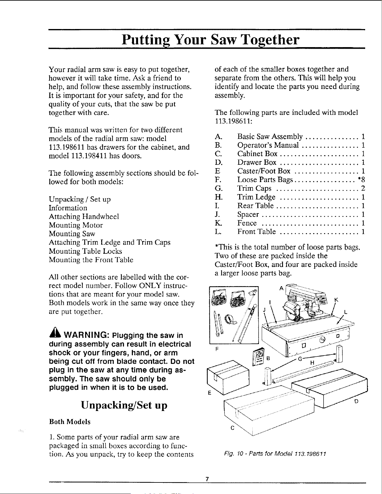
The following parts are included with model
113.198611:
A.
B.
C.
D.
E
F.
G.
H.
I.
J.
tC
L
Basic Saw Assembly ............... 1
Operator's Manual ................ 1
Cabinet Box ...................... 1
Drawer Box ...................... 1
Caster/Foot Box .................. 1
Loose Parts Bags ................. *8
Trim Caps ....................... 2
Trim Ledge ...................... 1
Rear Table ....................... 1
Spacer ........................... 1
Fence ........................... 1
Front Table ...................... 1
"This is the total number of loose parts bags.
Two of these are packed inside the
Caster/Foot Box, and four are packed inside
a larger loose parts bag.
A
C
Fig, 10 - Parts for Model 113.198611
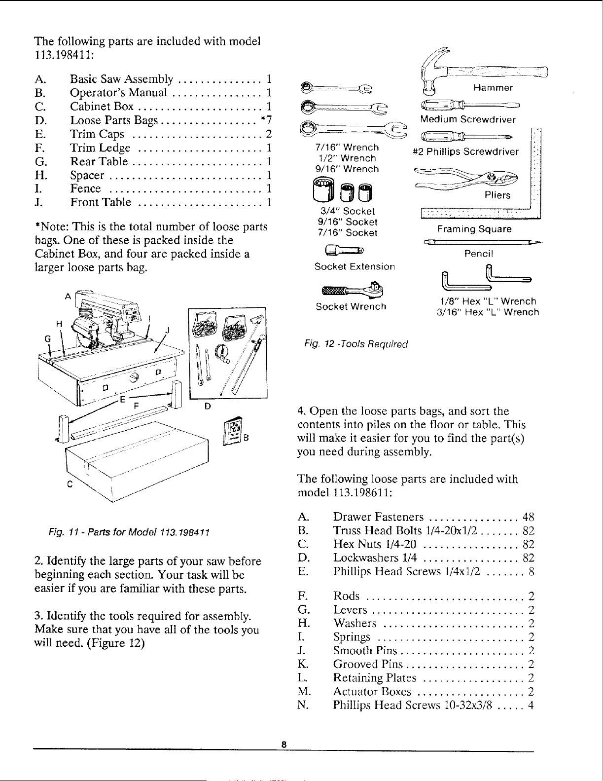
The following parts are included with model
113.198411:
A°
B.
C.
D.
E.
F.
G.
H.
I.
J.
Basic Saw Assembly ............... 1
Operator's Manual ................ 1
Cabinet Box ...................... 1
Loose Parts Bags ................. *7
Trim Caps ....................... 2
Trim Ledge ...................... 1
Rear Table ....................... 1
Spacer ........................... 1
Fence ........................... 1
Front Table ...................... 1
*Note: This is the total number of loose parts
bags. One of these is packed inside the
Cabinet Box, and four are packed inside a
larger loose parts bag.
G
A
H
J
Fig. 11 - Parts for Model 113.198411
2. Identify the large parts of your saw before
beginning each section. Your task will be
easier if you are familiar with these parts.
3. Identify the tools required for assembly.
Make sure that you have all of the tools you
will need. (Figure 12)
7/16" Wrench
1/2" Wrench
9/16" Wrench
3/4" Socket
9/16" Socket
7/16" Socket
Socket Extension
Socket Wrench
Medium Screwdriver
#2 Phillips Screwdriver
Pliers
Framing Square
Pencil
1/8" Hex "L" Wrench
3/16" Hex "L" Wrench
Fig. 12 -Tools Required
4. Open the loose parts bags, and sort the
contents into piles on the floor or table. This
will make it easier for you to find the part(s)
you need during assembly.
The following loose parts are included with
model 113.198611:
A.
B.
C.
D.
E.
Drawer Fasteners ................ 48
Truss Head Bolts 1/4-20xl/2 ....... 82
Hex Nuts 1/4-20 ................. 82
Lockwashers 1/4 ................. 82
Phillips Head Screws 1/4xl/2 ....... 8
F.
G.
H.
I.
J.
K.
L.
M.
N.
Rods ............................ 2
Levers ........................... 2
Washers ......................... 2
Springs .......................... 2
Smooth Pins ...................... 2
Grooved Pins ..................... 2
Retaining Plates .................. 2
Actuator Boxes ................... 2
Phillips Itead Screws 10-32x3/8 ..... 4
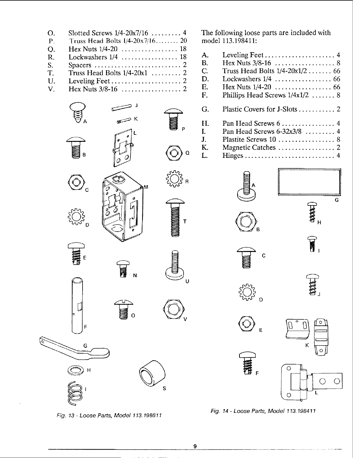
O,
P.
O.
R.
S.
T.
U.
V.
Slotted Screws 1/4-20x7/16 ......... 4
Truss Head Bolts I/4-20x7/16 ........ 20
Hex Nuts 1/4-20 ................. 18
Lockwashers 1/4 ................. 18
Spacers .......................... 2
Truss Head Bolts 1/4-20xl ......... 2
Leveling Feet ..................... 2
Hex Nuts 3/8-16 .................. 2
C
M
° I
i
B
F
N
U
Fig. 13 - Loose Parts, Model 113.198611
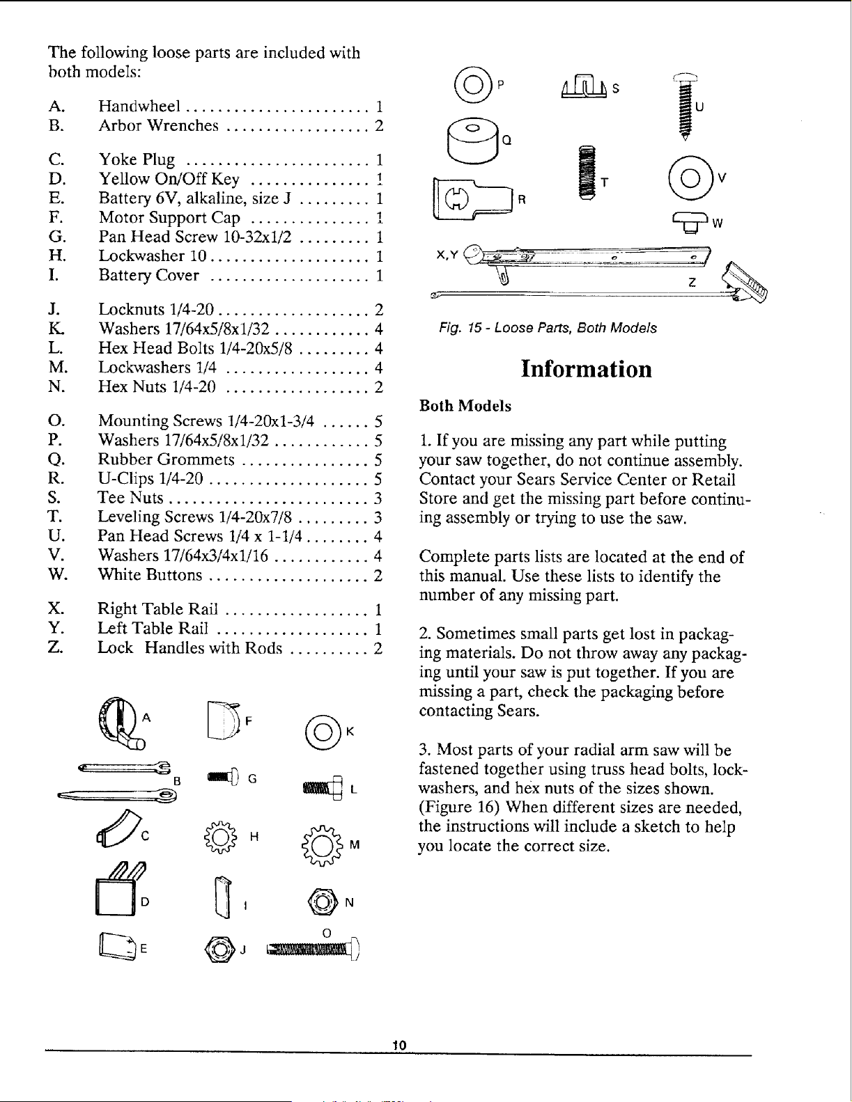
The following loose parts are included with
model 113.198411:
A.
B.
C.
D.
E.
F.
Leveling Feet ..................... 4
Hex Nuts 3/8-16 .................. 8
Truss Head Bolts 1/4-20xl/2 ....... 66
Lockwashers 1/4 ................. 66
Hex Nuts 1/4-20 ................. 66
Phillips Head Screws 1/4xl/2 ....... 8
G. Plastic Covers for J-Slots ........... 2
H°
I.
J.
K.
L.
Pan Head Screws 6 ................ 4
Pan Head Screws 6-32x3/8 ......... 4
Plastite Screws 10 ................. 8
Magnetic Catches ................. 2
Hinges ........................... 4
C
G
Fig. 14 - Loose Parts, Model 113.198411
9
The following loose parts are included with
both models:
A.
B.
Handwheel ....................... 1
Arbor Wrenches .................. 2
Ci
D.
E.
G°
H.
Jo
K.
L.
M.
N.
Yoke Plug ....................... 1
Yellow On/Off Key ............... !
Battery 6V, alkaline, size J ......... 1
Motor Support Cap ............... !
Pan Head Screw 10-32xl/2 ......... 1
Lockwasher 10 .................... 1
Battery Cover .................... 1
Locknuts 1/4-20 ................... 2
Washers 17/64x5/8x1/32 ............ 4
Hex Head Bolts 1/4-20x5/8 ......... 4
Lockwashers 1/4 .................. 4
Hex Nuts 1/4-20 .................. 2
O,
P.
O.
R.
S.
T.
U.
V.
W.
Mounting Screws 1/4-20xl-3/4 ...... 5
Washers 17/64x5/8x1/32 ............ 5
Rubber Grommets ................ 5
U-Clips 1/4-20 .................... 5
Tee Nuts ......................... 3
Leveling Screws 1/4-20x7/8 ......... 3
Pan Head Screws 1/4 x 1-1/4 ........ 4
Washers 17/64x3/4xl!16 ............ 4
White Buttons .................... 2
X.
Y.
Z.
Right Table Rail .................. 1
Left Table Rail ................... 1
Lock Handles with Rods .......... 2
II, o=
©°
I}i; R
©v
._ z %
Fig. 15 - Loose Parts, Both Models
Information
Both Models
1. If you are missing any part while putting
your saw together, do not continue assembly.
Contact your Sears Service Center or Retail
Store and get the missing part before continu-
ing assembly or trying to use the saw.
Complete parts lists are located at the end of
this manual. Use these lists to identify the
number of any missing part.
2. Sometimes small parts get lost in packag-
ing materials. Do not throw away any packag-
ing until your saw is put together. If you are
missing a part, check the packaging before
contacting Sears.
3. Most parts of your radial arm saw will be
fastened together using truss head bolts, lock-
washers, and hex nuts of the sizes shown.
(Figure 16) When different sizes are needed,
the instructions will include a sketch to help
you locate the correct size.
10
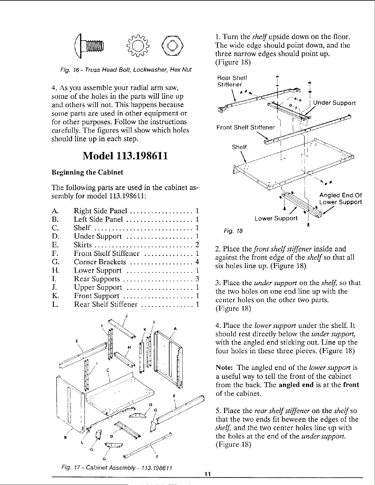
Fig. 16 - Truss Head Bolt, Lockwasher, Hex Nut
4. As you assemble your radial arm saw,
some of the holes in the parts will line up
and others will not. This happens because
some parts are used in other equipment or
for other purposes. Follow the instructions
carefully. The figures will show which holes
should line up in each step.
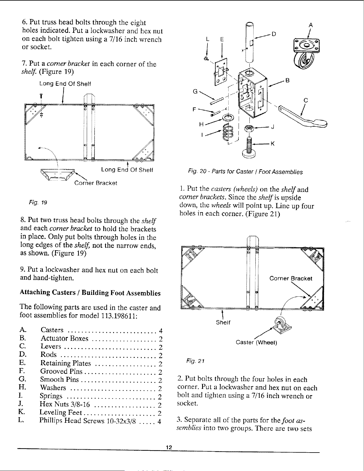
Model 113.198611
1. Turn the shelf upside down on the floor.
The wide edge should point down, and the
three narrow edges should point up.
(Figure 18)
Rear Shelf T
Stiffener _ '_
, /-___ I Under Support
Front Shelf Stiffener
Shelf
\
Beginning the Cabinet
The following parts are used in the cabinet as-
sembly for model 113.198611:
A.
B.
C.
D.
E.
F.
G.
H.
I.
J.
K.
L.
Right Side Panel .................. 1
Left Side Panel ................... 1
Shelf ............................ 1
Under Support ................... 1
Skirts ............................ 2
Front Shelf Stiffener .............. 1
Corner Brackets .................. 4
Lower Support ................... 1
Rear Supports .................... 3
Upper Support ................... 1
Front Support .................... 1
Rear Shelf Stiffener ............... 1
E
\
J
I
\
H
I
/
Fig. 17 - Cabinet Ass embly - 113.198611
11
Fig. 18
Angled End Of
Lower Support
* tt /
Lower Support
2. Place the front shelf stiffener inside and
against the front edge of the shelf so that all
six holes line up. (Figure 18)
3. Place the under support on the shelf, so that
the two holes on one end line up with the
center holes on the other two parts.
(Figure 18)
4. Place the lower support under the shelf. It
should rest directly below the under support,
with the angled end sticking out. Line up the
four holes in these three pieces. (Figure 18)
Note: The angled end of the lower support is
a useful way to tell the front of the cabinet
from the back. The angled end is at the front
of the cabinet.
5. Place the rear shelf stiffener on the shelf so
that the two ends fit beween the edges of the
shelf, and the two center holes line up with
the holes at the end of the under support.
(Figure 18)
6. Put truss head bolts through the eight
holesindicated. Put a lockwasherand hex nut
on eachbolt tighten usinga 7/16 inch wrench
or socket.
7. Put a comer bracket in each corner of the
shelf (Figure 19)
Long End Of Shelf
Long End Of Shelf
_r Bracket
Fig. 19
8. PUt two truss head bolts through the shelf
and each comer bracket to hold the brackets
in place. Only put bolts through holes in the
long edges of the shelf, not the narrow ends,
as shown. (Figure 19)
9. PUt a lockwasher and hex nut on each bolt
and hand-tighten.
Attaching Casters / Building Foot Assemblies
The following parts are used in the caster and
foot assemblies for model 113.198611:
A.
B.
C.
D.
E.
G°
H.
I.
J.
K.
L.
Casters .......................... 4
Actuator Boxes ................... 2
Levers ........................... 2
Rods ............................ 2
Retaining Plates .................. 2
Grooved Pins ..................... 2
Smooth Pins ...................... 2
Washers ......................... 2
Springs .......................... 2
Hex Nuts 3/8-16 .................. 2
Leveling Feet ..................... 2
Phillips Head Screws 10-32x3/8 ..... 4
C
Fig. 20 - Parts for Caster / Foot Assembfies
1. Put the casters" (wheels) on the shelf and
comer brackets. Since the shelf is upside
down, the wheeL_ will point up. Line up four
holes in each corner. (Figure 21)
Corner Bracket_
Shelf
Caster (Wheel)
Fig. 21
2. Put bolts through the four holes in each
corner. Put a lockwasher and hex nut on each
bolt and tighten using a 7/16 inch wrench or
socket.
3. Separate all of the parts for the foot as-
semblies into two groups. There are two sets
12
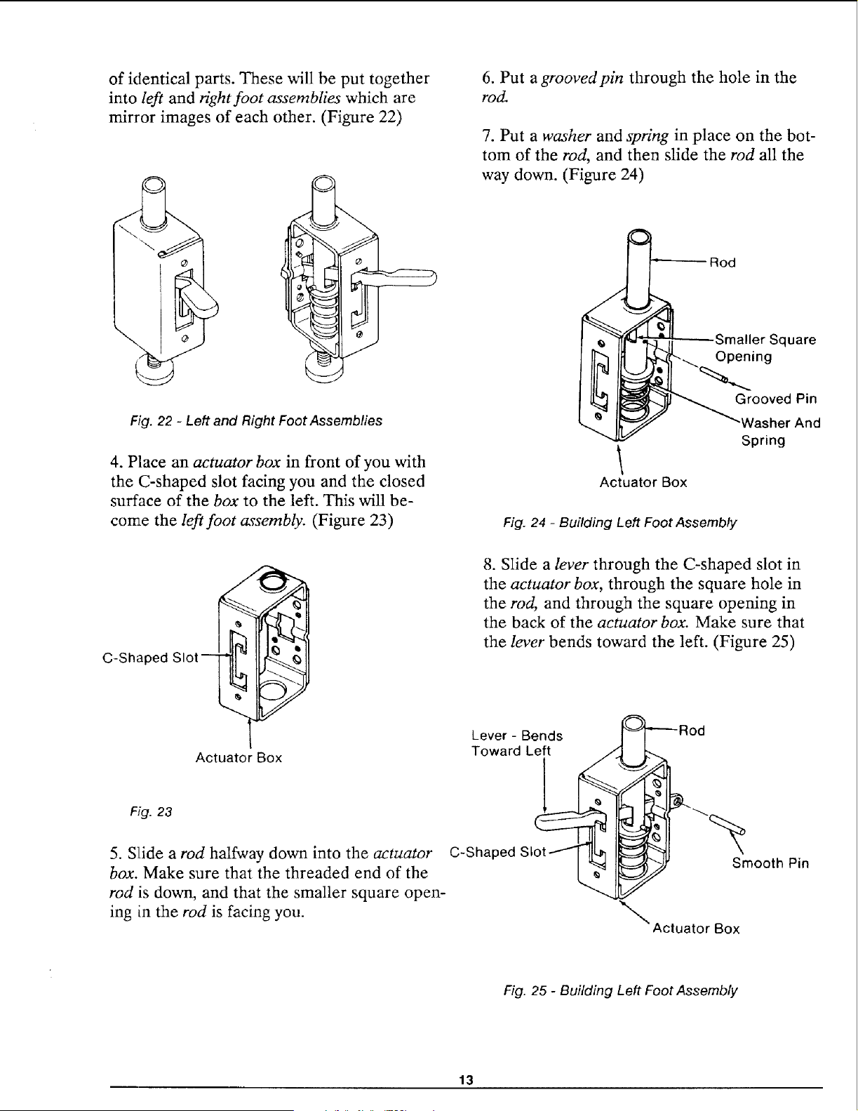
of identical parts. These will be put together
into left and right foot assemblies which are
mirror images of each other. (Figure 22)
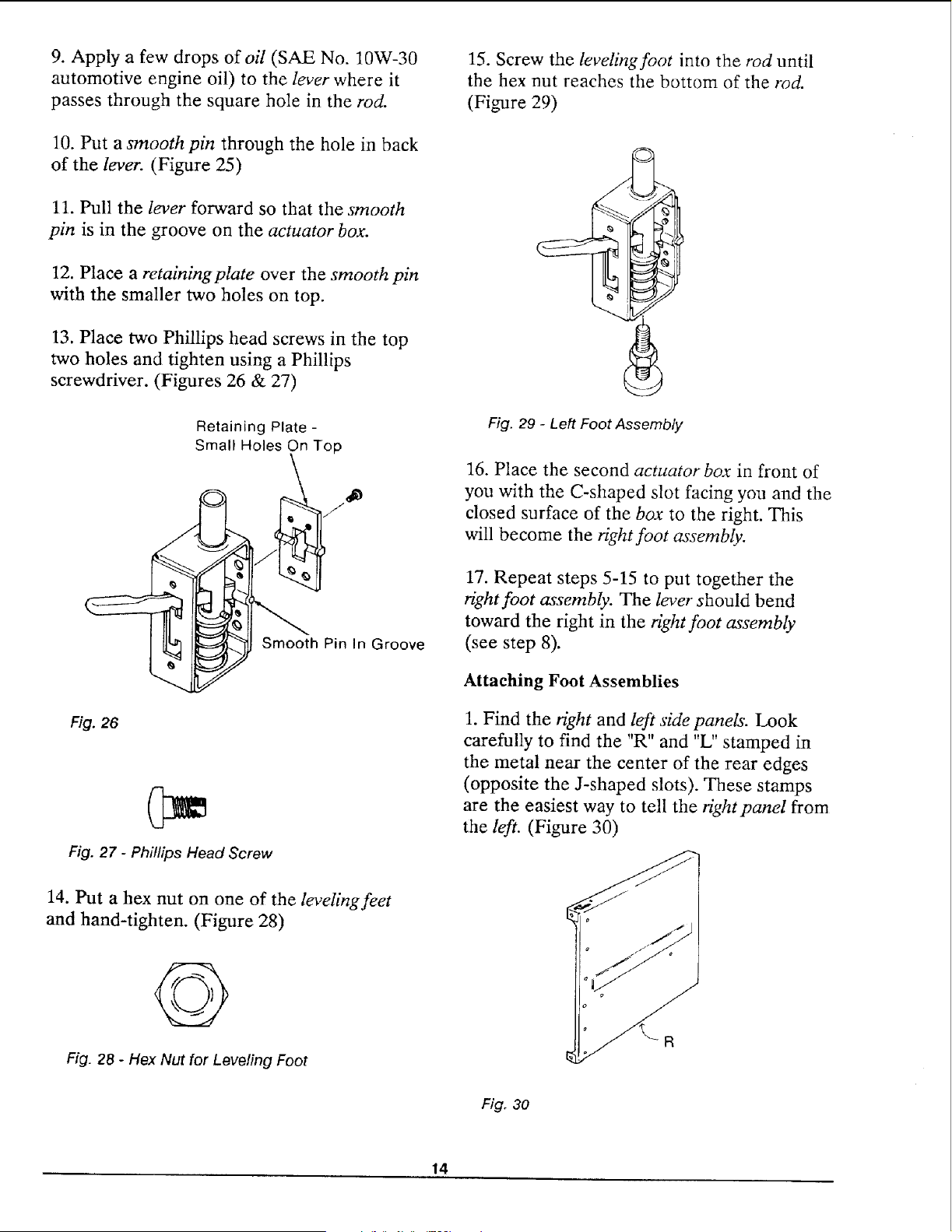
6. Put a groovedpin through the hole in the
rod.
7. Put a washer and spring in place on the bot-
tom of the rod, and then slide the rod all the
way down. (Figure 24)
Fig. 22 - Left and Right Foot Assemblies
4. Place an actuator box in front of you with
the C-shaped slot facing you and the closed
surface of the box to the left. This will be-
come the left foot assembly. (Figure 23)
Rod
Actuator Box
Fig. 24 - Building Left Foot Assembly
Square
Opening
Grooved Pin
"Washer And
Spring
C-Shaped
Slot
Actuator Box
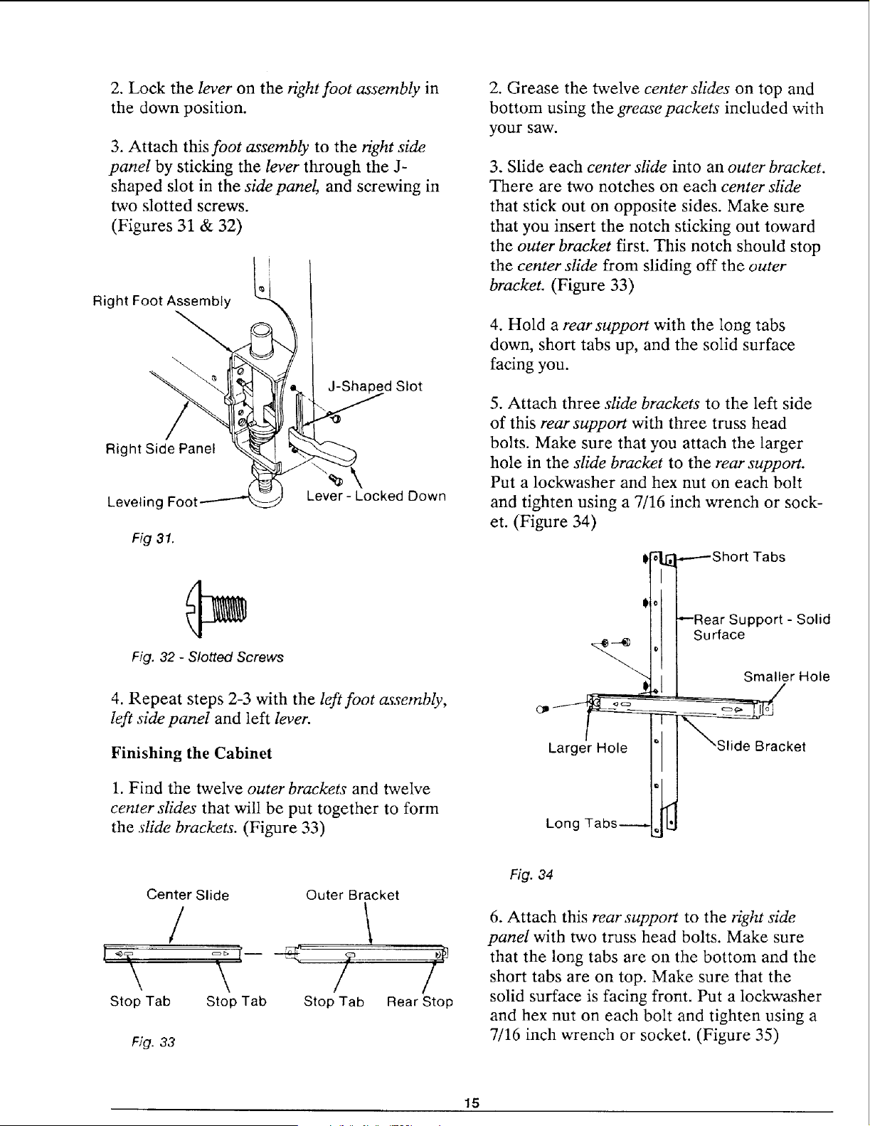
8. Slide a lever through the C-shaped slot in
the actuator box, through the square hole in
the rod, and through the square opening in
the back of the actuator box. Make sure that
the lever bends toward the left. (Figure 25)
Lever - Bends
Toward Left
Fig. 23
5. Slide a rod halfway down into the actuator
box. Make sure that the threaded end of the
rod is down, and that the smaller square open-
ing in the rod is facing you.
C-Shale
Smooth Pin
_'_ Actuator Box
Fig. 25 - Building Left Foot Assembly
13
9. Apply a few drops ofoil (SAE No. 10W-30
automotive engine oil) to the lever where it
passes through the square hole in the rod.
10. Put a smooth pin through the hole in back
of the lever. (Figure 25)
11. Pull the lever forward so that the smooth
pin is in the groove on the actuator box.
12. Place a retaining plate over the smooth pin
with the smaller two holes on top.
13. Place two Phillips head screws in the top
two holes and tighten using a Phillips
screwdriver. (Figures 26 & 27)
Retaining Plate-
Small Holes On Top
J
Smooth Pin In Groove
Fig. 26
Fig. 27 - Phillips Head Screw
14. Put a hex nut on one of the leveling feet
and hand-tighten. (Figure 28)
Fig. 28 - Hex Nut for Leveling Foot
15. Screw the leveling foot into the rod until
the hex nut reaches the bottom of the rod.
(Figure 29)
Fig. 29 - Left Foot Assembly
16. Place the second actuator box in front of
you with the C-shaped slot facing you and the
closed surface of the box to the right. This
will become the right foot assembly.
17. Repeat steps 5-15 to put together the
right foot assembly. The lever should bend
toward the right in the right foot assembly
(see step 8).
Attaching Foot Assemblies
1. Find the right and left side panels. Look
carefully to find the "R" and "L" stamped in
the metal near the center of the rear edges
(opposite the J-shaped slots). These stamps
are the easiest way to tell the right panel from
the left. (Figure 30)
Fig. 30
14
2. Lock the lever on the right foot assembly in
the down position.
3. Attach this foot assembly to the right side
panel by sticking the lever through the J-
shaped slot in the side panel, and screwing in
two slotted screws.
(Figures 31 & 32)
Right Foot Assembly
"_ J-Shaped Slot
Right Side Panel
Leveling Foot
Fig31.
Lever- Locked Down
Fig. 32 - Slotted Screws
4. Repeat steps 2-3 with the left foot assembly,
left side panel and left lever.
Finishing the Cabinet
1. Find the twelve outer brackets and twelve
center slides that will be put together to form
the slide brackets. (Figure 33)
2. Grease the twelve center slides on top and
bottom using the grease packets included with
your saw.
3. Slide each center slide into an outer bracket.
There are two notches on each center slide
that stick out on opposite sides. Make sure
that you insert the notch sticking out toward
the outer bracket first. This notch should stop
the center slide from sliding off the outer
bracket. (Figure 33)
4. Hold a rear support with the long tabs
down, short tabs up, and the solid surface
facing you.
5. Attach three slide brackets to the left side
of this rear support with three truss head
bolts. Make sure that you attach the larger
hole in the slide bracket to the rear support.
Put a lockwasher and hex nut on each bolt
and tighten using a 7/16 inch wrench or sock-
et. (Figure 34)
i[_ _-----Short Tabs
tl ---Rear Support- Solid
H S°r'a e
er Hole
acke,
Long Tabs--------, _]
Center Slide Outer Bracket
/
\ / /
Stop Tab Stop Tab Rear StopStop Tab
Fig. 33
Fig. 34
6. Attach this rear support to the right side
panel with two truss head bolts. Make sure
that the long tabs are on the bottom and the
short tabs are on top. Make sure that the
solid surface is facing front. Put a lockwasher
and hex nut on each bolt and tighten using a
7/16 inch wrench or socket. (Figure 35)
15
Rear
Short
Long Tabs
Right Side Panel
Inside Edge Of Side Panel
Front
Fig. 35
7. Repeat steps 4 - 6 with another rear sup-
port and the left side panel. Attach the slide
brackets to the right side of this rear support
8. Attach the front end of each slide bracket
to a hole on the inside edge of the sidepanels
with six truss head bolts. Put a lockwasher
and hex nut on each bolt and tighten with a
7/16 inch wrench or socket. (Figure 35)
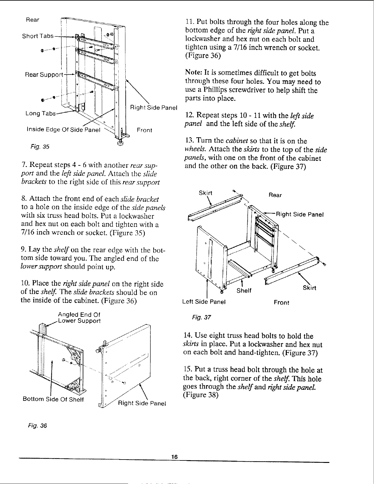
9. Lay the shelf on the rear edge with the bot-
tom side toward you. The angled end of the
lower support should point up.
10. Place the fight sidepanel on the right side
of the shelf. The slide brackets should be on
the inside of the cabinet. (Figure 36)
Angled End Of
Support
Bottom Side Of Shelf
Right Side Panel
11. Put bolts through the four holes along the
bottom edge of the Hght side panel. Put a
lockwasher and hex nut on each bolt and
tighten using a 7/16 inch wrench or socket.
(Figure 36)
Note: It is sometimes difficult to get bolts
through these four holes. You may need to
use a Phillips screwdriver to help shift the
parts into place.
12. Repeat steps 10 - 11 with the left side
panel and the left side of the shelf.
13. Turn the cabinet so that it is on the
wheels. Attach the skirts to the top of the side
panels, with one on the front of the cabinet
and the other on the back. (Figure 37)
Rear
Side Panel
Shelf
Left Side Panel Front
Skirt
Fig. 37
14. Use eight truss head bolts to hold the
skirts in place. Put a lockwasher and hex nut
on each bolt and hand-tighten. (Figure 37)
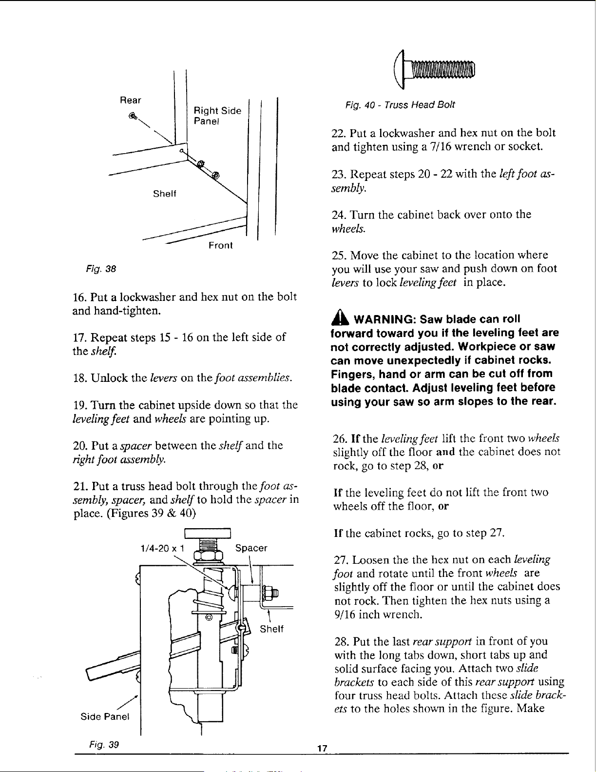
15. Put a truss head bolt through the hole at
the back, right corner of the shelf. This hole
goes through the shelf and right side panel.
(Figure 38)
Fig. 36
16
Rear
Right Side
Panel
Shelf
Front
Fig. 38
16. Put a lockwasher and hex nut on the bolt
and hand-tighten.
17. Repeat steps 15 - 16 on the left side of
the shelf.
18. Unlock the levers on the foot assemblies.
19. Turn the cabinet upside down so that the
leveling feet and wheels are pointing up.
20. Put a spacer between the shelf and the
right foot assembly.
21. Put a truss head bolt through the foot as-
sembly, spacer, and shelf to hold the spacer in
place. (Figures 39 & 40)
1/4-20xl _-----_._ Spacer
Shelf
Fig. 39
17
Fig. 40 - Truss Head Bolt
22. Put a lockwasher and hex nut on the bolt
and tighten using a 7/16 wrench or socket.
23. Repeat steps 20 - 22 with the left foot as-
sembly.
24. Turn the cabinet back over onto the
wheels.
25. Move the cabinet to the location where
you will use your saw and push down on foot
levers to lock leveling feet in place.
_1_ WARNING: Saw blade can roll
forward toward you if the leveling feet are
not correctly adjusted. Workpiece or saw
can move unexpectedly if cabinet rocks.
Fingers, hand or arm can be cut off from
blade contact. Adjust leveling feet before
using your saw so arm slopes to the rear.
26. If the leveling feet lift the front two wheels
slightly off the floor and the cabinet does not
rock, go to step 28, or
If the leveling feet do not lift the front two
wheels off the floor, or
If the cabinet rocks, go to step 27.
27. Loosen the the hex nut on each leveling
foot and rotate until the front wheels are
slightly off the floor or until the cabinet does
not rock. Then tighten the hex nuts using a
9/16 inch wrench.
28. Put the last rear support in front of you
with the long tabs down, short tabs up and
solid surface facing you. Attach two slide
brackets to each side of this rear support using
four truss head bolts. Attach these slide brack-
ets to the holes shown in the figure. Make
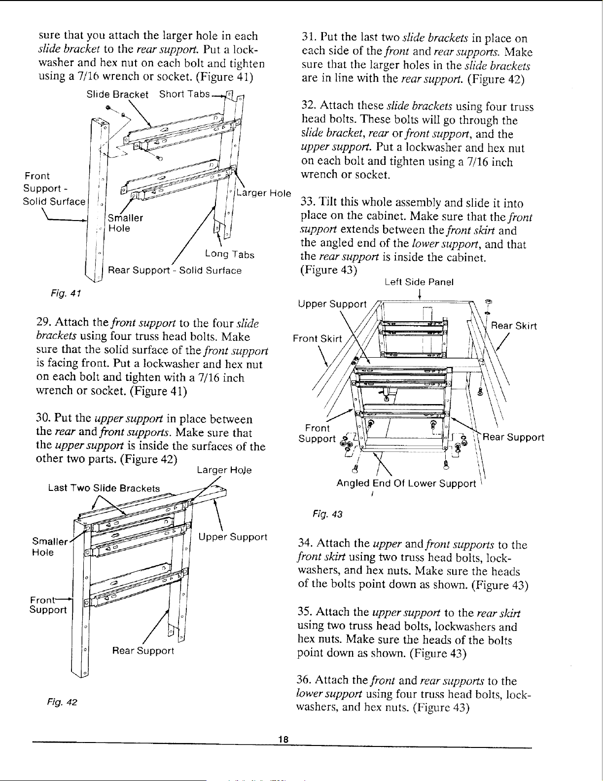
sure that you attach the larger hole in each
slide bracket to the rear support. Put a lock-
washer and hex nut on each bolt and tighten
using a 7/16 wrench or socket. (Figure 41)
Slide Bracket Short
Front
Support -
Solid Surface
Fig. 41
er Hole
S L!ler
; Hole
i,l Long Tabs
\L Rear Support - Solid Surface
29. Attach the front support to the four slide
brackets using four truss head bolts. Make
sure that the solid surface of the front support
is facing front. Put a lockwasher and hex nut
on each bolt and tighten with a 7/16 inch
wrench or socket. (Figure 41)
30. Put the upper support in place between
the rear and front supports. Make sure that
the upper support is inside the surfaces of the
other two parts. (Figure 42)
Larger Ho_e
Last Two Slide Brackets
Smaller-
Hole
Upper Support
Support
Rear Support
Fig. 42
31. Put the last two slide brackets in place on
each side of the front and rear supports. Make
sure that the larger holes in the slide brackets
are in line with the rear support. (Figure 42)
32. Attach these sfide brackets using four truss
head bolts. These bolts will go through the
slide bracket, rear or front support, and the
upper support. Put a lockwasher and hex nut
on each bolt and tighten using a 7/16 inch
wrench or socket.
33. Tilt this whole assembly and slide it into
place on the cabinet. Make sure that the front
support extends between the front s/drt and
the angled end of the lower support, and that
the rear support is inside the cabinet.
(Figure 43)
Upper Support
\
Front Skirt
Left Side Panel
I
Rear Skirt
/
/
Front
Support
Angled End Of Lower Support
I
Fig. 43
"Rear Support
34. Attach the upper and front supports to the
front skirt using two truss head bolts, lock-
washers, and hex nuts. Make sure the heads
of the bolts point down as shown. (Figure 43)
35. Attach the upper support to the rear skirt
using two truss head bolts, lockavashers and
hex nuts. Make sure the heads of the bolts
point down as shown. (Figure 43)
36. Attach the front and rear supports to the
lower support using four truss head bolts, lock-
washers, and hex nuts. (Figure 43)
18
37. Tighten all screws, except those on the
front and rear skirts, using a 7/16 inch wrench
or socket.
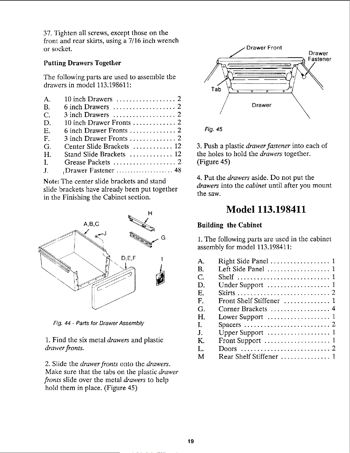
Putting Drawers Together
The following parts are used to assemble the
drawers in model 113.198611:
A.
B.
C.
D.
E.
F.
G.
H.
I.
J.
10 inch Drawers .................. 2
6 inch Drawers ................... 2
3 inch Drawers ................... 2
10 inch Drawer Fronts ............. 2
6 inch Drawer Fronts .............. 2
3 inch Drawer Fronts .............. 2
Center Slide Brackets ............ 12
Stand Slide Brackets ............. 12
Grease Packets ................... 2
_Drawer Fastener .................... 48
Note: The center slide brackets and stand
slide brackets have already been put together
in the Finishing the Cabinet section.
D,E,F I
Fig. 44 - Parts for Drawer Assembly
1. Find the six metal drawers and plastic
drawer fronts.
2. Slide the drawer fronts onto the drawers.
Make sure that the tabs on the plastic drawer
fronts slide over the metal drawers to help
hold them in place. (Figure 45)
Tab
Drawer Front
Drawer
Fig. 45
3. Push a plastic drawer fastener into each of
the holes to hold the drawers together.
(Figure 45)
4. Put the drawers aside. Do not put the
drawers into the cabinet until after you mount
the saw.
Model 113.198411
Building the Cabinet
1. The following parts are used in the cabinet
assembly for model 113.198411:
A°
B.
C.
D.
E.
F.
G.
H.
I.
J.
K.
L.
M
Right Side Panel .................. 1
Left Side Panel ................... 1
Shelf ............................ 1
Under Support ................... 1
Skirts ............................ 2
Front Shelf Stiffener .............. 1
Corner Brackets .................. 4
Lower Support ................... 1
Spacers .......................... 2
Upper Support ................... 1
Front Support .................... 1
Doors ........................... 2
Rear Shelf Stiffener ............... 1
19
I G
G
F
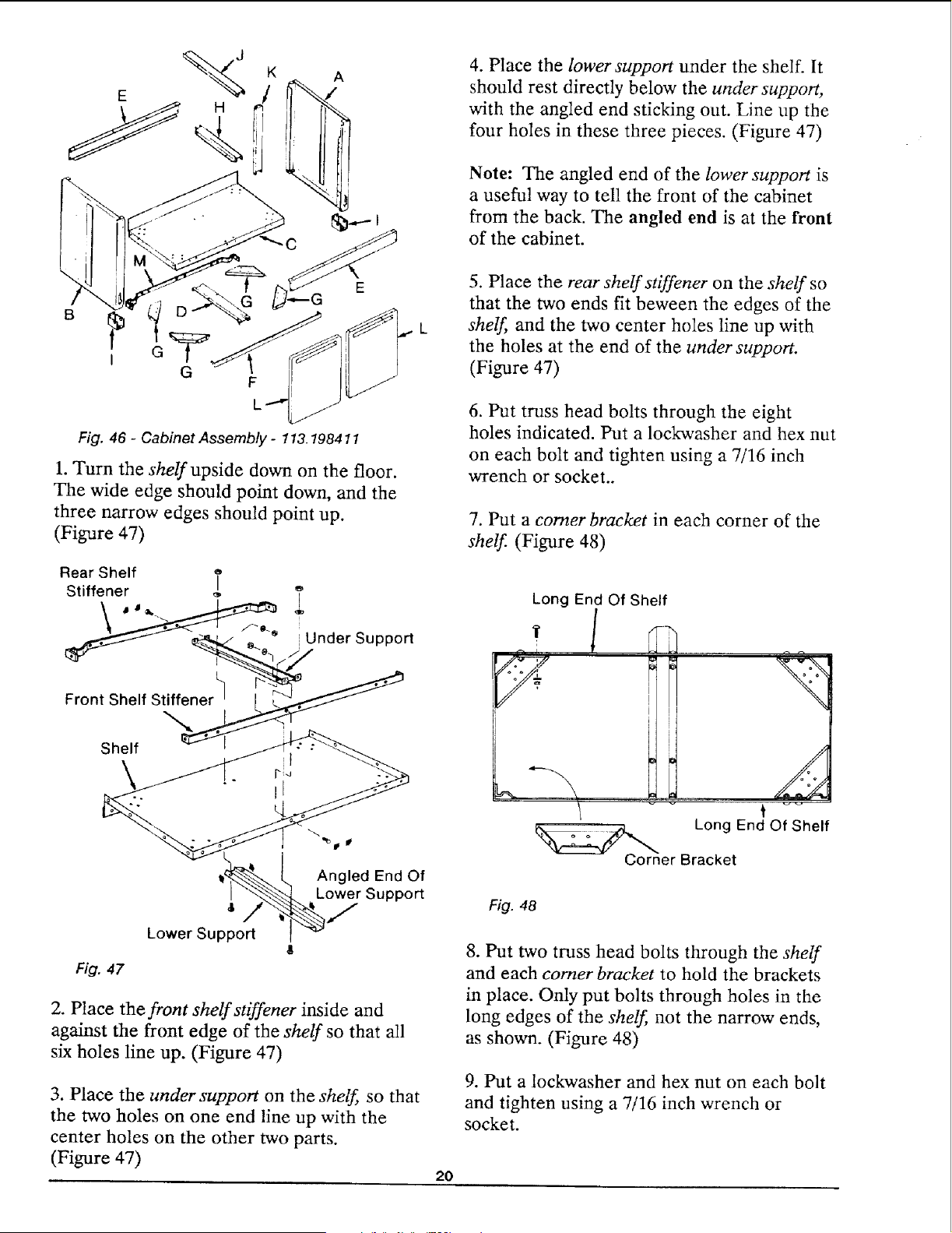
Fig. 46 - Cabinet Assembly - 113.198411
1. Turn the shelf upside down on the floor.
The wide edge should point down, and the
three narrow edges should point up.
(Figure 47)
Fig. 47
8
Lower Support
Angled End Of
Lower Support
2. Place the front shelf stiffener inside and
against the front edge of the shelf so that all
six holes line up. (Figure 47)
3. Place the under support on the shelf so that
the two holes on one end line up with the
center holes on the other two parts.
(Figure 47)
2O
4. Place the lower support under the shelf. It
should rest directly below the under support,
with the angled end sticking out. Line up the
four holes in these three pieces. (Figure 47)
Note: The angled end of the lower support is
a useful way to tell the front of the cabinet
from the back. The angled end is at the front
of the cabinet.
5. Place the rear shelf stiffener on the shelf so
that the two ends fit beween the edges of the
shelf, and the two center holes line up with
the holes at the end of the under support.
(Figure 47)
6. Put truss head bolts through the eight
holes indicated. Put a lockwasher and hex nut
on each bolt and tighten using a 7/16 inch
wrench or socket..
7. PUt a comer bracket in each corner of the
shelf. (Figure 48)
Long End Of Shelf
Long End Of Shelf
o
Corner Bracket
Fig. 48
8. Put two truss head bolts through the shelf
and each comer bracket to hold the brackets
in place. Only put bolts through holes in the
long edges of the shelf, not the narrow ends,
as shown. (Figure 48)
9. Put a lockwasher and hex nut on each bolt
and tighten using a 7/16 inch wrench or
socket.
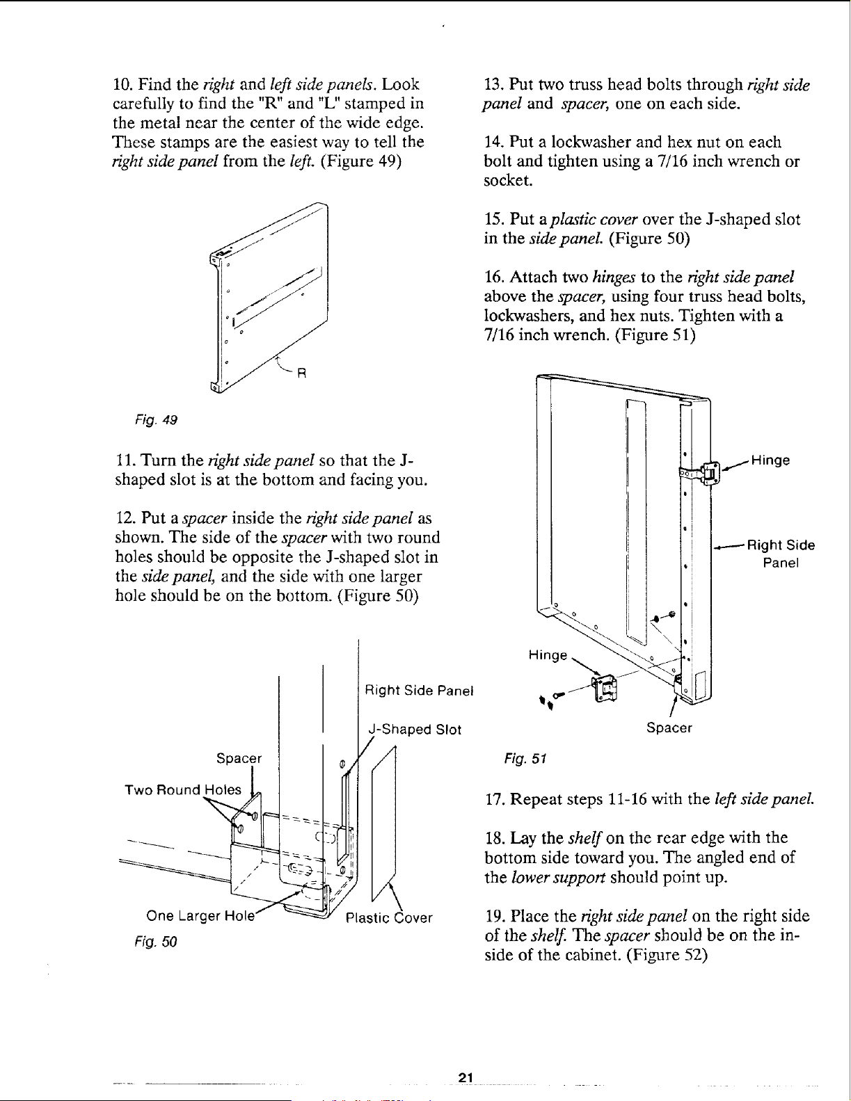
10.Find the right and left side panels. Look
carefully to find the "R" and "L" stamped in
the metal near the center of the wide edge.
These stamps are the easiest way to tell the
right side panel from the left. (Figure 49)
13. Put two truss head bolts through right side
panel and spacer, one on each side.
14. Put a lockwasher and hex nut on each
bolt and tighten using a 7/16 inch wrench or
socket.
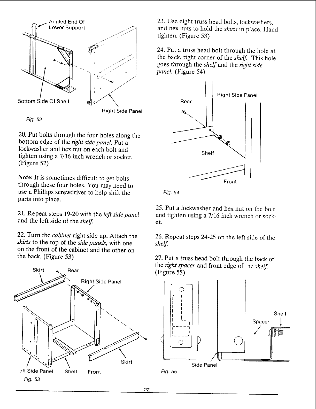
15. Put aplastic cover over the J-shaped slot
in the side panel (Figure 50)
16. Attach two hinges to the right side panel
above the spacer, using four truss head bolts,
lockwashers, and hex nuts. Tighten with a
7/16 inch wrench. (Figure 51)
Fig. 49
11. Turn the right side panel so that the J-
shaped slot is at the bottom and facing you.
12. Put a spacer inside the right side panel as
shown. The side of the spacer with two round
holes should be opposite the J-shaped slot in
the sidepanel, and the side with one larger
hole should be on the bottom. (Figure 50)
.----- Right Side
Panel
Spacer
Two Round Holes
One Larger
Ffg. 50
Right Side Panel
-Shaped Slot
/
,4
Plastic Cover
Hinge
Fig. 51
Spacer
17. Repeat steps 11-16 with the left sidepanel.
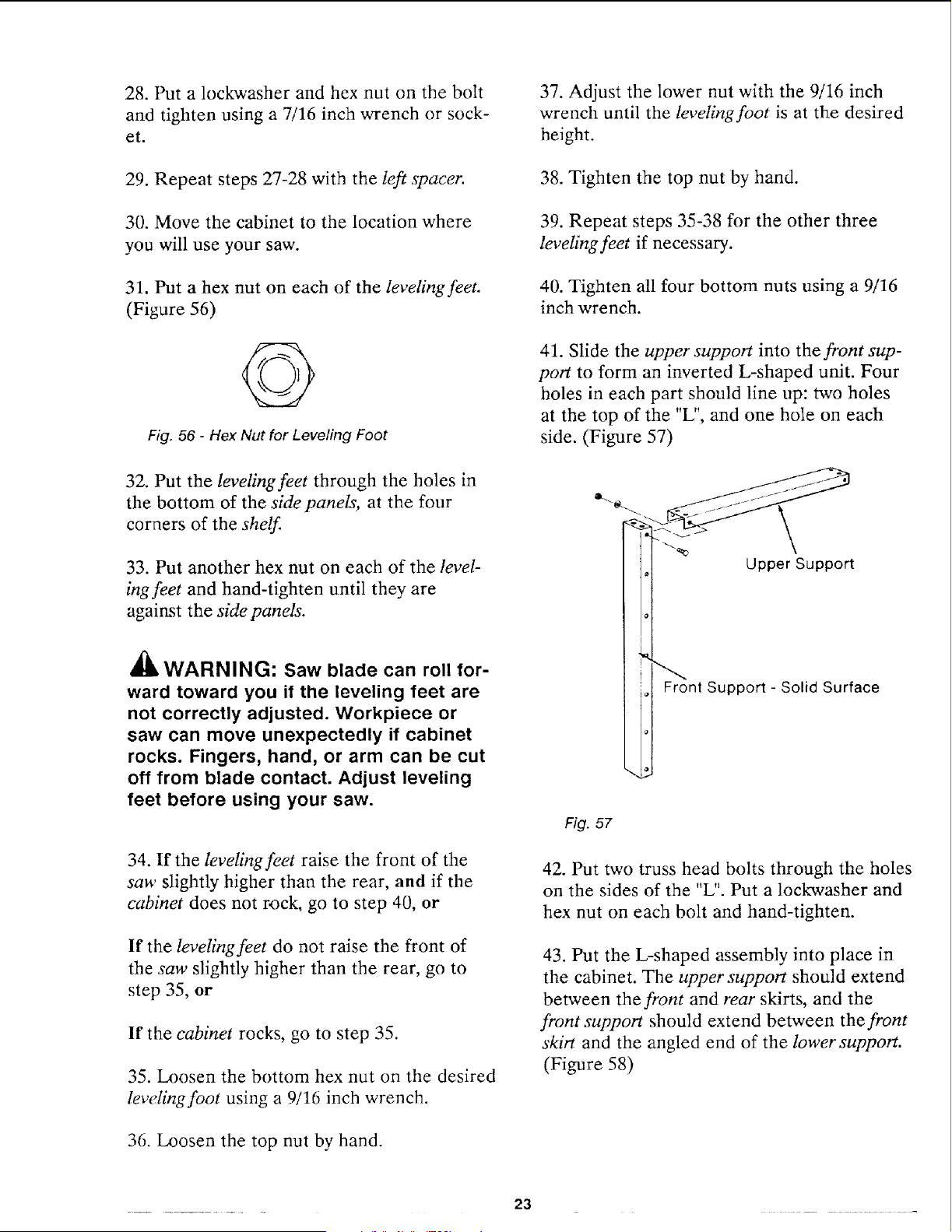
18. Lay the shelf on the rear edge with the
bottom side toward you. The angled end of
the lower support should point up.
19. Place the right side panel on the right side
of the shelf. The spacer should be on the in-
side of the cabinet. (Figure 52)
21
Angled End Of
J Lower Support
Bottom Side Of Shelf
Fig. 52
Right Side Panel
23. Use eight truss head bolts, lockwashers,
and hex nuts to hold the skirts in place. Hand-
tighten. (Figure 53)
24. Put a truss head bolt through the hole at
the back, right corner of the shelf. This hole
goes through the shelf and the right side
panel. (Figure 54)
Rear
Right Side Panel
20. Put bolts through the four holes along the
bottom edge of the right side panel. Put a
lockwasher and hex nut on each bolt and
tighten using a 7/16 inch wrench or socket.
(Figure 52)
Note: It is sometimes difficult to get bolts
through these four holes. You may need to
use a Phillips screwdriver to help shift the
parts into place.
21. Repeat steps 19-20 with the left side panel
and the left side of the shelf
22. Turn the cabinet right side up. Attach the
skirts to the top of the side panels, with one
on the front of the cabinet and the other on
the back. (Figure 53)
Skirt ,_ Rear
Right Side Panel
Left Side Panel
Fig. 53
Shelf Front
Skirt
Shelf
Fig. 54
Front
25. Put a lockwasher and hex nut on the bolt
and tighten using a 7/16 inch wrench or sock-
et.
26. Repeat steps 24-25 on the left side of the
shelf
27. Put a truss head bolt through the back of
the right spacer and front edge of the shelf.
(Figure 55)
1 i
i l
l l
L
I I
I I
Fig. 55
/
Side Panel
Shelf
Spacer 1
©
22
28. Put a lockwasher and hex nut on the bolt
and tighten using a 7/16 inch wrench or sock-
et.
29. Repeat steps 27-28 with the left spacer.
30. Move the cabinet to the location where
you will use your saw.
31. Put a hex nut on each of the leveling feet.
(Figure 56)
Fig. 56 - Hex Nut for Leveling Foot
32. Put the leveling feet through the holes in
the bottom of the side panels, at the four
corners of the shelf.
33. Put another hex nut on each of the level
ingfeet and hand-tighten until they are
agairkst the side panels.
a'k
WARNING: Saw blade can roll for-
ward toward you if the leveling feet are
not correctly adjusted. Workpiece or
saw can move unexpectedly if cabinet
rocks. Fingers, hand, or arm can be cut
off from blade contact. Adjust leveling
feet before using your saw.
34. If the leveling feet raise the front of the
saw slightly higher than the rear, and if the
cabinet does not rock, go to step 40, or
If the leveling feet do not raise the front of
the saw slightly higher than the rear, go to
step 35, or
If the cabinet rocks, go to step 35.
35. Loosen the bottom hex nut on the desired
leveling foot using a 9/16 inch wrench.
36. Loosen the top nut by hand.
37. Adjust the lower nut with the 9/16 inch
wrench until the leveling foot is at the desired
height.
38. Tighten the top nut by hand.
39. Repeat steps 35-38 for the other three
leveling feet if necessary.
40. Tighten all four bottom nuts using a 9/16
inch wrench.
41. Slide the upper support into the front sup-
port to form an inverted L-shaped unit. Four
holes in each part should line up: two holes
at the top of the "L", and one hole on each
side. (Figure 57)
o-.
, Upper Support
nt Support - Solid Surface
Fig. 57
42. Put two truss head bolts through the holes
on the sides of the "L". Put a lockwasher and
hex nut on each bolt and hand-tighten.
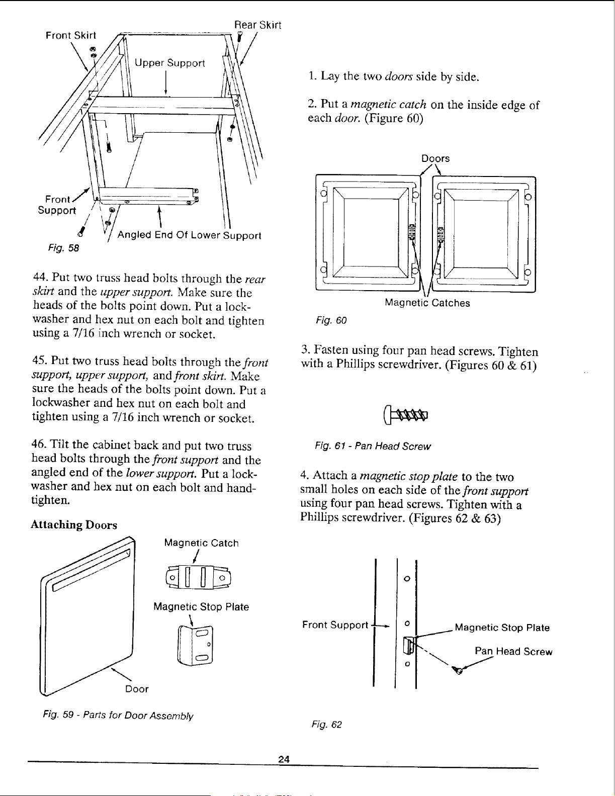
43. Put the L-shaped assembly into place in
the cabinet. The upper support should extend
between the front and rear skirts, and the
front support should extend between the front
skirt and the angled end of the lower support.
(Figure 58)
23
Front Skirt
Rear Skirt
Suppo_
/
g
Fig. 58
Angled End Of Lower Support
44. Put two truss head bolts through the rear
skirt and the upper support. Make sure the
heads of the bolts point down. Put a lock-
washer and hex nut on each bolt and tighten
using a 7/16 inch wrench or socket.
45. Put two truss head bolts through the front
support, upper support, and front skirt. Make
sure the heads of the bolts point down. Put a
lockwasher and hex nut on each bolt and
tighten using a 7/16 inch wrench or socket.
46. Tilt the cabinet back and put two truss
head bolts through the front support and the
angled end of the lower support. Put a lock-
washer and hex nut on each bolt and hand-
tighten.
Attaching Doors
oor
Magnetic Catch
/
Magnetic Stop Plate
Fig. 59 - Parts for Door Assembly
1. Lay the two doors side by side.
2. Put a magnetic catch on the inside edge of
each door. (Figure 60)
Doors
\
Magnetic Catches
Fig. 60
3. Fasten using four pan head screws. Tighten
with a Phillips screwdriver. (Figures 60 & 61)
Fig. 61 - Pan Head Screw
4. Attach a rnagnetic stop plate to the two
small holes on each side of the front support
using four pan head screws. Tighten with a
Phillips screwdriver. (Figures 62 & 63)
Front Support
O
o
/ Magnetic Stop Plate
Pan Head Screw
Fig. 62
24
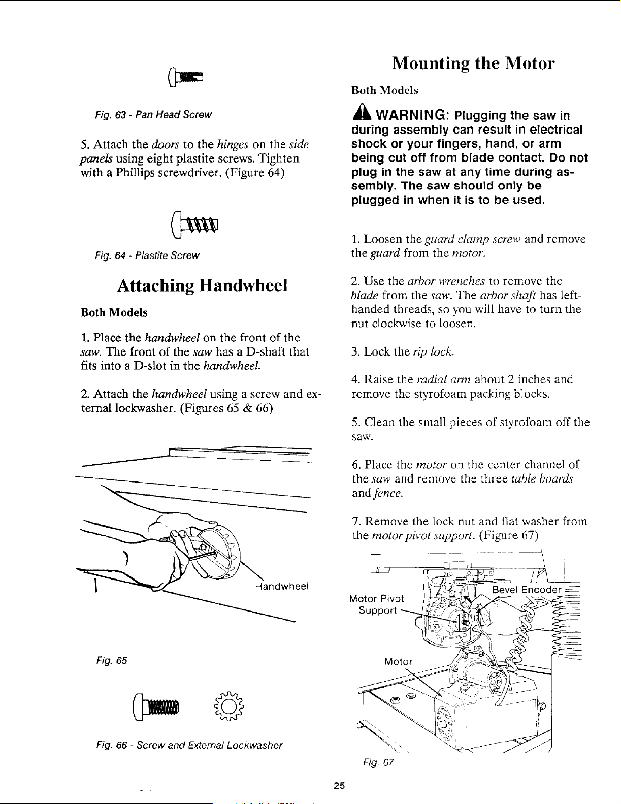
Fig. 63 - Pan Head Screw
5. Attach the doors to the hinges on the side
panels using eight plastite screws. Tighten
with a Phillips screwdriver. (Figure 64)
Fig. 64 - Plastite Screw
Attaching Handwheel
Both Models
1. Place the handwheel on the front of the
saw. The front of the saw has a D-shaft that
fits into a D-slot in the handwheeI.
2. Attach the handwheel using a screw and ex-
ternal lockwasher. (Figures 65 & 66)
Mounting the Motor
Both Models
_lh WARNING: Plugging the saw in
during assembly can result in electrical
shock or your fingers, hand, or arm
being cut off from blade contact. Do not
plug in the saw at any time during as-
sembly. The saw should only be
plugged in when it is to be used.
1. Loosen the guard clamp screw and remove
the guard from the motor.
2. Use the arbor wrenches to remove the
blade from the saw. The arbor shaft has left-
handed threads, so you will have to turn the
nut clockwise to loosen.
3. Lock the rip lock.
4. Raise the radial arm about 2 inches and
remove the styrofoam packing blocks.
5. Clean the small pieces of styrofoam off the
saw.
6. Place the motor on the center channel of
the saw and remove the three table boards
and fence.
7. Remove the lock nut and flat washer from
the motorpivot support. (Figure 67)
\
Bevel Encoder
Motor Pivot
Support
Fig. 65 Motor
Fig. 66 - Screw and External Lockwasher
25
8. Slide the beve! encoder to the top center
position so it will fit into the notch on the
motor support bracket. (Figure 67)
9. Slide the motor onto the motor pivot sup-
port. Make sure that the motor is firmly in
place.
10. Put the flat washer and locknut back in
place and tighten using a 3/4 inch socket
wrench. Move the bevel lock back and forth
as you tighten the locknut. Do not over-
tighten.
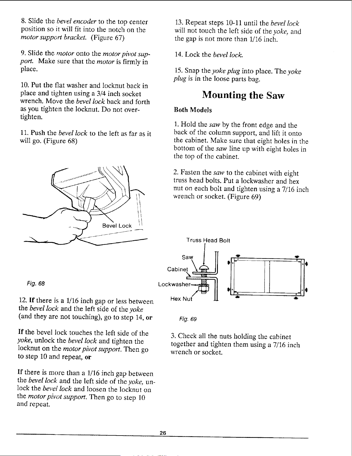
11. Push the bevel lock to the left as far as it
will go. (Figure 68)
BevelLock
13. Repeat steps 10-11 until the bevel lock
will not touch the left side of the yoke, and
the gap is not more than 1/16 inch.
14. Lock the bevel lock.
15. Snap the yoke plug into place. The yoke
plug is in the loose parts bag.
Mounting the Saw
Both Models
1. Hold the saw by the front edge and the
back of the column support, and lift it onto
the cabinet. Make sure that eight holes in the
bottom of the saw line up with eight holes in
the top of the cabinet.
2. Fasten the saw to the cabinet with eight
truss head bolts. Put a lockwasher and hex
nut on each bolt and tighten using a 7/16 inch
wrench or socket. (Figure 69)
Truss Head Bolt
Fig. 68
12. If there is a 1/16 inch gap or less between
the bevel lock and the left side of the yoke
(and they are not touching), go to step 14, or
Cabinet
\
Lock
Hex Nut
Fig. 69
,u, ,g-
-e- 41_
If the bevel lock touches the left side of the
yoke, unlock the bevel lock and tighten the
locknut on the motorpivot support. Then go
to step 10 and repeat, or
3. Check all the nuts holding the cabinet
together and tighten them using a 7/16 inch
wrench or socket.
If there is more than a 1/16 inch gap between
the bevel lock and the left side of the yoke, un-
lock the bevel lock and loosen the locknut on
the motorpivot support. Then go to step 10
and repeat.
26
Attaching Trim Ledge and
Trim Caps
Both Models
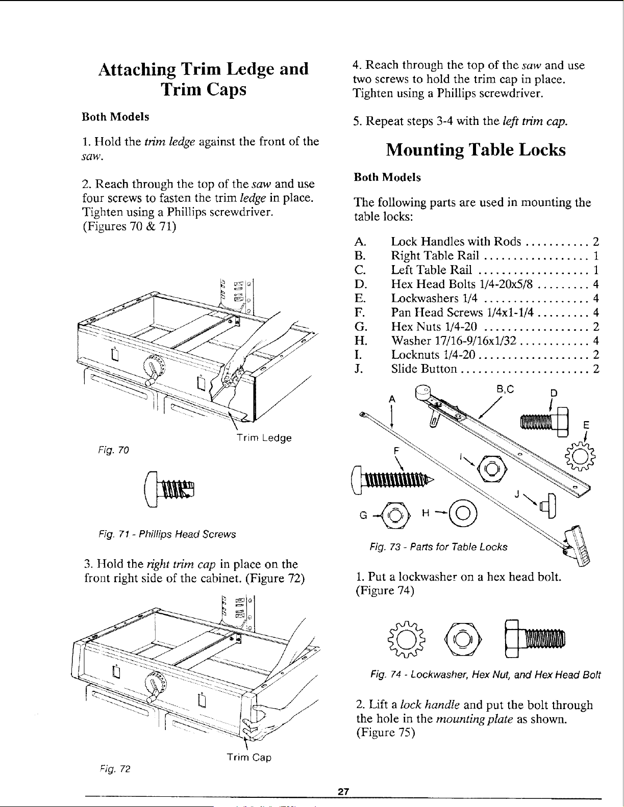
1. Hold the trim ledge against the front of the
saw.
2. Reach through the top of the saw and use
four screws to fasten the trim ledge in place.
Tighten using a Phillips screwdriver.
(Figures 70 & 71)
Fig. 70
Trim Ledge
Fig. 71- Phillips Head Screws
3. Hold the right trim cap in place on the
front right side of the cabinet. (Figure 72)
4. Reach through the top of the saw and use
two screws to hold the trim cap in place.
Tighten using a Phillips screwdriver.
5. Repeat steps 3-4 with the left trim cap.
Mounting Table Locks
Both Models
The following parts are used in mounting the
table locks:
Ao
B.
C.
D.
E.
F.
G.
H.
I.
J.
Lock Handles with Rods ........... 2
Right Table Rail .................. 1
Left Table Rail ................... 1
Hex Head Bolts 1/4-20x5/8 ......... 4
Lockwashers 1/4 .................. 4
Pan Head Screws 1/4x1-1/4 ......... 4
Hex Nuts 1/4-20 .................. 2
Washer 17/16-9/16xl/32 ............ 4
Locknuts 1/4-20 ................... 2
Slide Button ...................... 2
D
1
Fig. 73 - Parts for Table Locks
1. Put a lockwasher on a hex head bolt.
(Figure 74)
Fig. 72
Trim Cap
Fig. 74 - Lockwasher, Hex Nut, and Hex Head Bolt
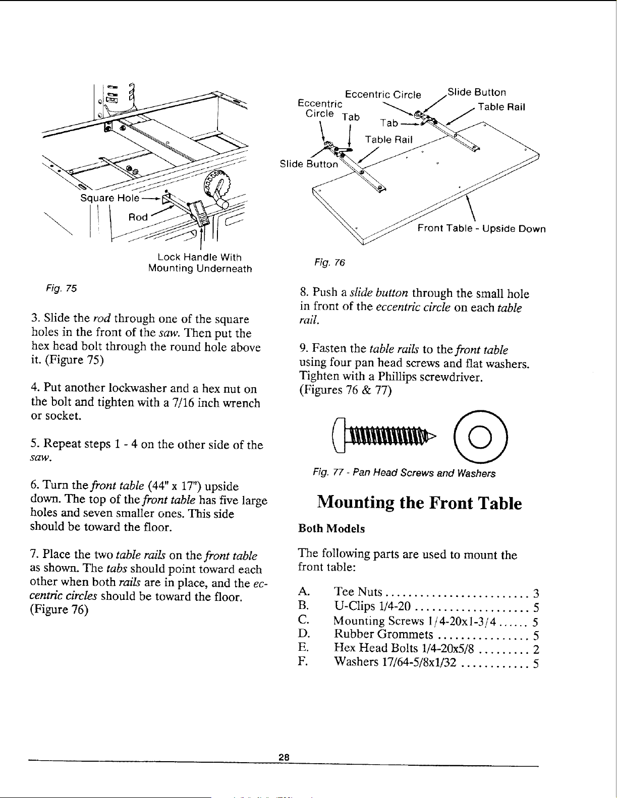
2. Lift a lock handle and put the bolt through
the hole in the mounting plate as shown.
(Figure 75)
27
\
Fig. 75
Square Hole
Lock Handle With
Mounting Underneath
3. Slide the rod through one of the square
holes in the front of the saw. Then put the
hex head bolt through the round hole above
it. (Figure 75)
4. Put another lockwasher and a hex nut on
the bolt and tighten with a 7/16 inch wrench
or socket.
5. Repeat steps 1 - 4 on the other side of the
saw.
6. Turn the front table (44" x 17") upside
down. The top of the front table has five large
holes and seven smaller ones. This side
should be toward the floor.
7. Place the two table rails on the front table
as shown. The tabs should point toward each
other when both rails are in place, and the ec-
centric circles should be toward the floor.
(Figure 76)
Eccentric Circle
Eccentric
Circle Tab
Slide Button
Rail
Slide
Front Table - Upside Down
Fig. 76
8. Push a slide button through the small hole
in front of the eccentric circle on each table
rail.
9. Fasten the table rails to the front table
using four pan head screws and flat washers.
Tighten with a Phillips screwdriver.
(Figures 76 & 77)
Fig. 77 - Pan Head Screws and Washers
Mounting the Front Table
Both Models
The following parts are used to mount the
front table:
A.
B.
C.
D.
E.
F.
Tee Nuts ......................... 3
U-Clips 1/4-20 .................... 5
Mounting Screws 1/4-20xi-3/4 ...... 5
Rubber Grommets ................ 5
Hex Head Bolts 1/4-20x5/8 ......... 2
Washers 17/64-5/8xl/32 ............ 5
28
D
A
B
1 E
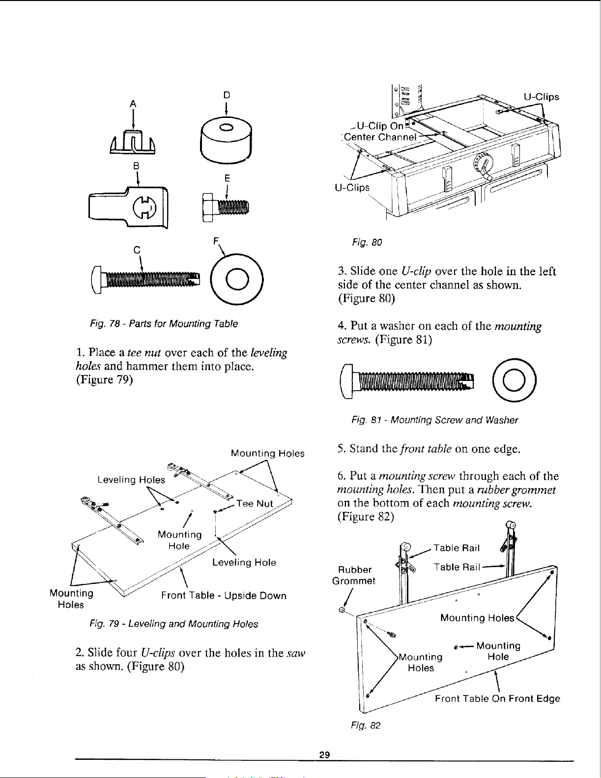
Fig. 78 - Parts for Mounting Table
1. Place a tee nut over each of the leveling
holes and hammer them into place.
(Figure 79)
U-Clips
/U-Clip On
_Center Channe
U-Clips
Fig. 80
3. Slide one U-clip over the hole in the left
side of the center channel as shown.
(Figure 80)
4. Put a washer on each of the mounting
screws. (Figure 81)
Fig. 81 - Mounting Screw and Washer
Mounting
Holes
Leveling Holes
Mounting Holes
Leveling Hole
Front Table - Upside Down
Fig. 79 - Leveling and Mounting Holes
2. Slide four U-clips over the holes in the saw
as shown. (Figure 80)
5. Stand the front table on one edge.
6. Put a mounting screw through each of the
mounting holes. Then put a rubber grommet
on the bottom of each mounting screw.
(Figure 82)
_,.._,. Table Rail _/
Rubber _-% Table Rail -----"lll_
GrommetIt,I _ /
_'_ __nti £g Holes/
t _Moon,ing .o,e_J _
I Holes o \
'_Front Edge
Fiq. 82
29
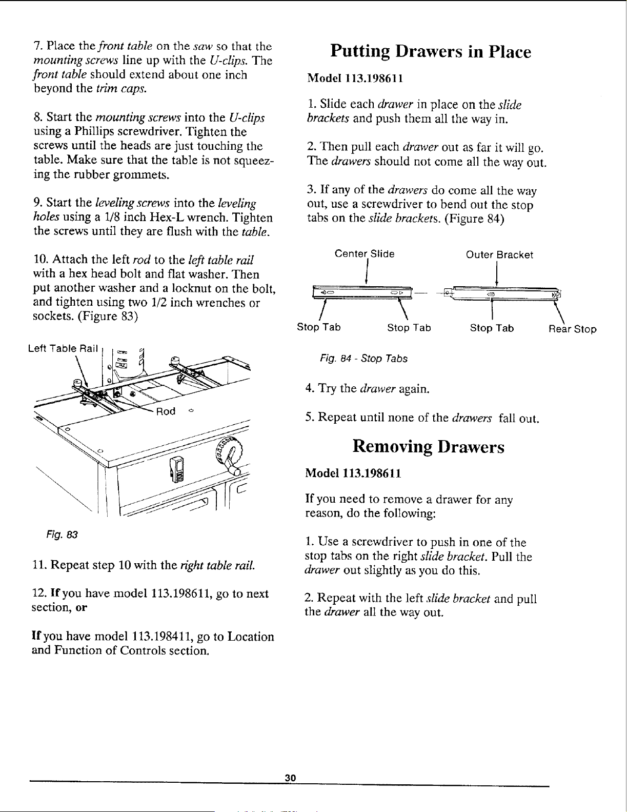
7. Place the front table on the saw so that the
mounting screws' line up with the U-clips. The
front table should extend about one inch
beyond the trim caps.
8. Start the mounting screws into the U-clips
using a Phillips screwdriver. Tighten the
screws until the heads are just touching the
table. Make sure that the table is not squeez-
ing the rubber grommets.
9. Start the leveling screws into the leveling
holes using a 1/8 inch Hex-L wrench. Tighten
the screws until they are flush with the table.
Putting Drawers in Place
Model 113.198611
1. Slide each drawer in place on the slide
brackets and push them all the way in.
2. Then pull each drawer out as far it will go.
The drawers should not come all the way out.
3. If any of the drawers do come all the way
out, use a screwdriver to bend out the stop
tabs on the slide brackets. (Figure 84)
10. Attach the left rod to the left table rail
with a hex head bolt and flat washer. Then
put another washer and a locknut on the bolt, I "_"
and tighten using two 1/2 inch wrenches or
sockets. (Figure 83)
/
Stop Tab
Left Table Rail
Center Slide Outer Bracket
1 1
Stop Tab Stop Tab Rear Stop
Fig. 84 - Stop Tabs
\
Fig. 83
11. Repeat step 10 with the right table rail.
12. Ifyou have model 113.198611, go to next
section, or
If you have model 113.198411, go to Location
and Function of Controls section.
4. Try the drawer again.
5. Repeat until none of the drawers fall out.
Removing Drawers
Model 113.198611
If you need to remove a drawer for any
reason, do the following:
1. Use a screwdriver to push in one of the
stop tabs on the right slide bracket. Pull the
drawer out slightly as you do this.
2. Repeat with the left slide bracket and pull
the drawer all the way out.
30
Location and Function of Controls
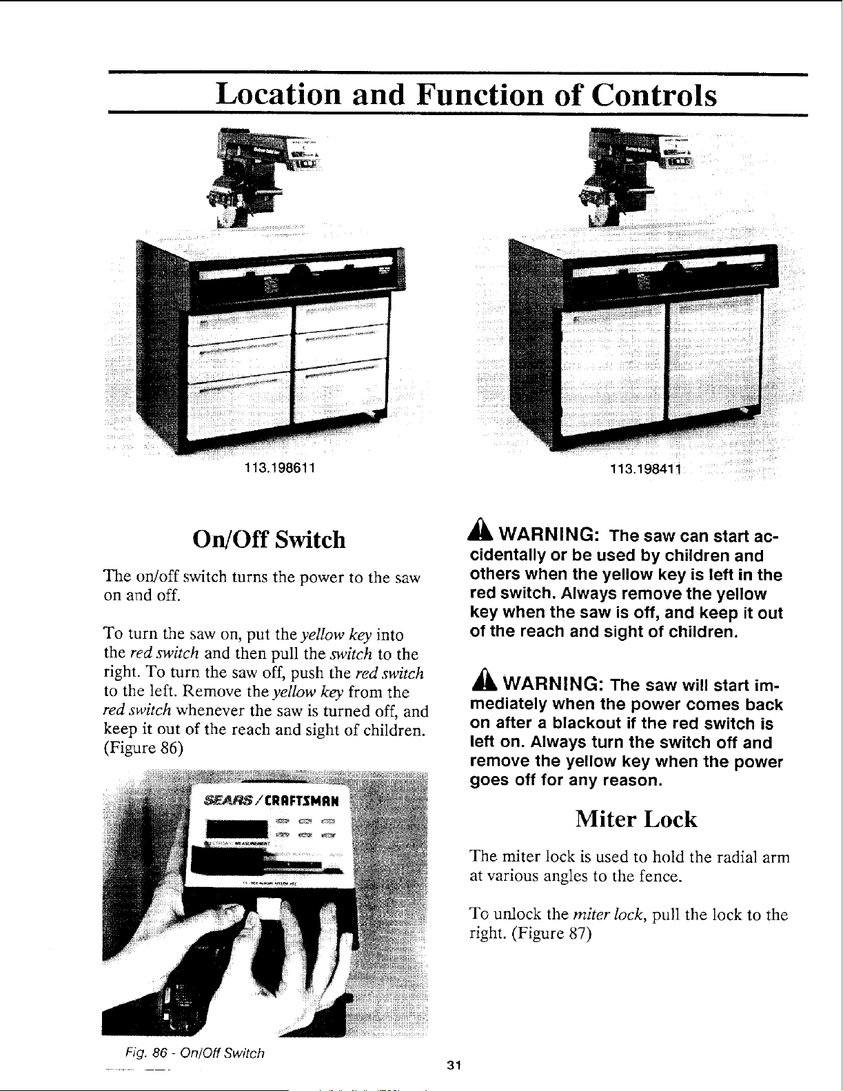
113.198611
113.198411
On/Off Switch
The on/off switch turns the power to the saw
on and off.
To turn the saw on, put the yellow key into
the red switch and then pull the switch to the
right. To turn the saw off, push the red switch
to the left. Remove the yellow key from the
red switch whenever the saw is turned off, and
keep it out of the reach and sight of children.
(Figure 86)
WARNING: The saw can start ac-
cidentally or be used by children and
others when the yellow key is left in the
red switch. Always remove the yellow
key when the saw is off, and keep it out
of the reach and sight of children.
'_ WARNING: The saw will start im-
mediately when the power comes back
on after a blackout if the red switch is
left on. Always turn the switch off and
remove the yellow key when the power
goes off for any reason.
Miter Lock
The miter lock is used to hold the radial arm
at various angles to the fence.
To unlock the miter lock, pull the lock to the
right. (Figure 87)
Fig. 86 - On/Off Switch
.... 31
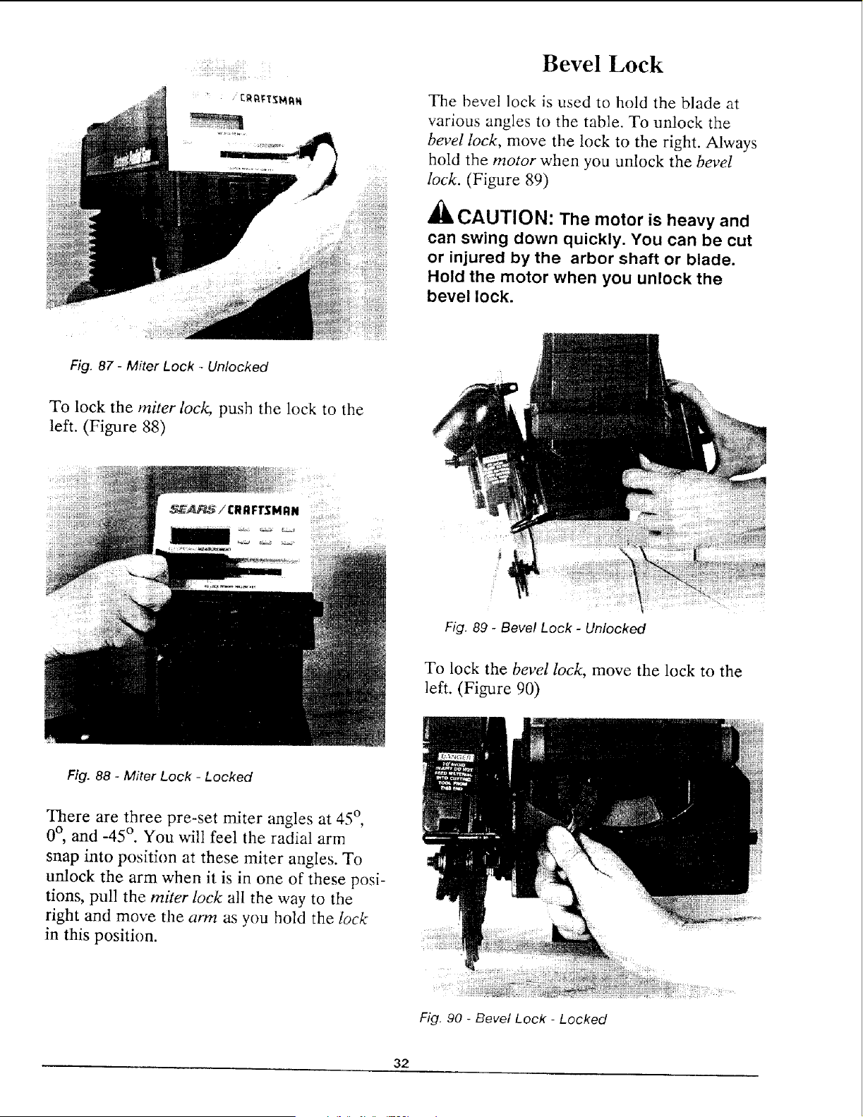
Bevel Lock
The bevel lock is used to hold the blade at
various angles to the table. To unlock the
bevel lock, move the lock to the right. Always
hold the motor when you unlock the bevel
lock. (Figure 89)
CAUTION: The motor is heavy and
can swing down quickly. You can be cut
or injured by the arbor shaft or blade.
Hold the motor when you unlock the
bevel lock.
Fig. 87 - Miter Lock - Unlocked
To lock the miter lock, push the lock to the
left. (Figure 88)
_A_!C..FrS...
Fig. 89 - Bevel Lock - Unlocked
To lock the bevel lock, move the lock to the
left. (Figure 90)
Fig. 88 - Miter Lock - Locked
There are three pre-set miter angles at 45 °,
0°, and -45 °. You will feel the radial arm
snap into position at these miter angles. To
unlock the arm when it is in one of these posi-
tions, pull the miter lock all the way to the
right and move the arm as you hold the lock
in this position.
Fig. 90 - Bevel Lock - Locked
32
There are five pre-set bevel angles at -90 °,
-45 °, 0°, 45 °, and 90 °. To unlock the bevel
lock when the blade is at one of these angles,
move the bevel lock all the way to the right
and turn the motor while holding the lock in
this position.
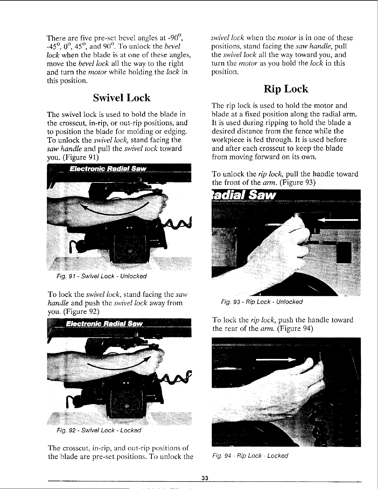
Swivel Lock
The swivel lock is used to hold the blade in
the crosscut, in-rip, or out-rip positions, and
to position the blade for molding or edging.
To unlock the swivel lock, stand facing the
san' handle and pull the swivel rock toward
you. (Figure 91)
Fig. 91 - Swivel Lock - Unlocked
swivel lock when the motor is in one of these
positions, stand facing the saw handle, pull
the swivel lock all the way toward you, and
turn the motor as you hold the lock in this
position.
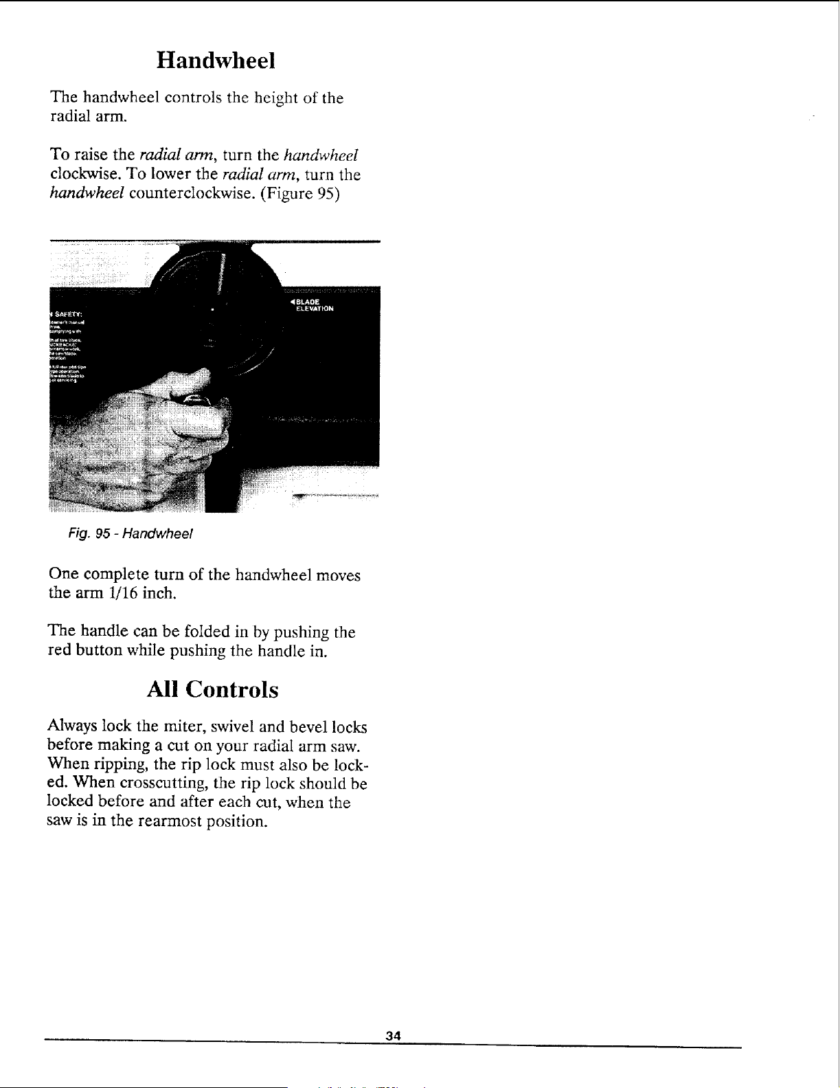
Rip Lock
The rip lock is used to hold the motor and
blade at a fixed position along the radial arm.
It is used during ripping to hold the blade a
desired distance from the fence while the
workpiece is fed through. It is used before
and after each crosscut to keep the blade
from moving forward on its own.
To unlock the rip lock, pull the handle toward
the front of the arm. (Figure 93)
To lock the swivel lock, stand facing the saw
handle and push the swivel lock away from
you. (Figure 92)
Fig. 92 - Swivel Lock - Locked
Fig. 93 - Rip Lock - Unlocked
To lock the rip lock, push the handle toward
the rear of the arm. (Figure 94)
The crosscut, in-rip, and out-rip posJtJons of
the blade are pre-set positions. To unlock the
Fig. 94 - Rip Lock - Locked
33
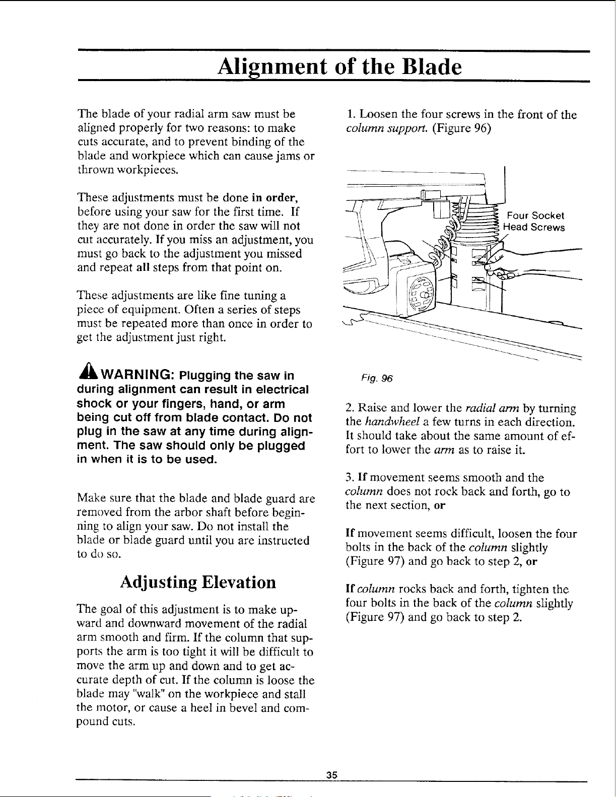
Handwheel
The handwheel controls the height of the
radial arm.
To raise the radial arm, turn the handwheel
clockwise. To lower the radial arm, turn the
handwheel counterclockwise. (Figure 95)
Fig. 95 - Handwheel
One complete turn of the handwheel moves
the arm 1/16 inch.
The handle can be folded in by pushing the
red button while pushing the handle in.
All Controls
Always lock the miter, swivel and bevel locks
before making a cut on your radial arm saw.
When ripping, the rip lock must also be lock-
ed. When crosscutting, the rip lock should be
locked before and after each cut, when the
saw is in the rearmost position.
34
Alignment of the Blade
The blade of your radial arm saw must be
aligned properly for two reasons: to make
cuts accurate, and to prevent binding of the
blade and workpiece which can cause jams or
thrown workpieces.
These adjustments must be done in order,
before using your saw for the first time. If
they are not done in order the saw will not
cut accurately. If you miss an adjustment, you
must go back to the adjustment you missed
and repeat all steps from that point on.
These adjustments are like fine tuning a
piece of equipment. Often a series of steps
must be repeated more than once in order to
get the adjustment just right.
41&WARNING: Plugging the saw in
during alignment can result in electrical
shock or your fingers, hand, or arm
being cut off from blade contact. Do not
plug in the saw at any time during align-
ment. The saw should only be plugged
in when it is to be used.
Make sure that the blade and blade guard are
removed from the arbor shaft before begin°
ning to align your saw. Do not install the
blade or blade guard until you are instructed
to do so.
Adjusting Elevation
The goal of this adjustment is to make up-
ward and downward movement of the radial
arm smooth and firm. If the column that sup-
ports the arm is too tight it will be difficult to
move the arm up and down and to get ac-
curate depth of cut. If the column is loose the
blade may "walk" on the workpiece and stall
the motor, or cause a heel in bevel and com-
pound cuts.
1. Loosen the four screws in the front of the
column support. (Figure 96)
Four Socket
Head Screws
Fig. 96
2. Raise and lower the radial arm by turning
the handwheeI a few turns in each direction.
It should take about the same amount of ef-
fort to lower the arm as to raise it.
3. If movement seems smooth and the
column does not rock back and forth, go to
the next section, or
If movement seems difficult, loosen the four
bolts in the back of the column slightly
(Figure 97) and go back to step 2, or
If column rocks back and forth, tighten the
four bolts in the back of the column slightly
(Figure 97) and go back to step 2.
35
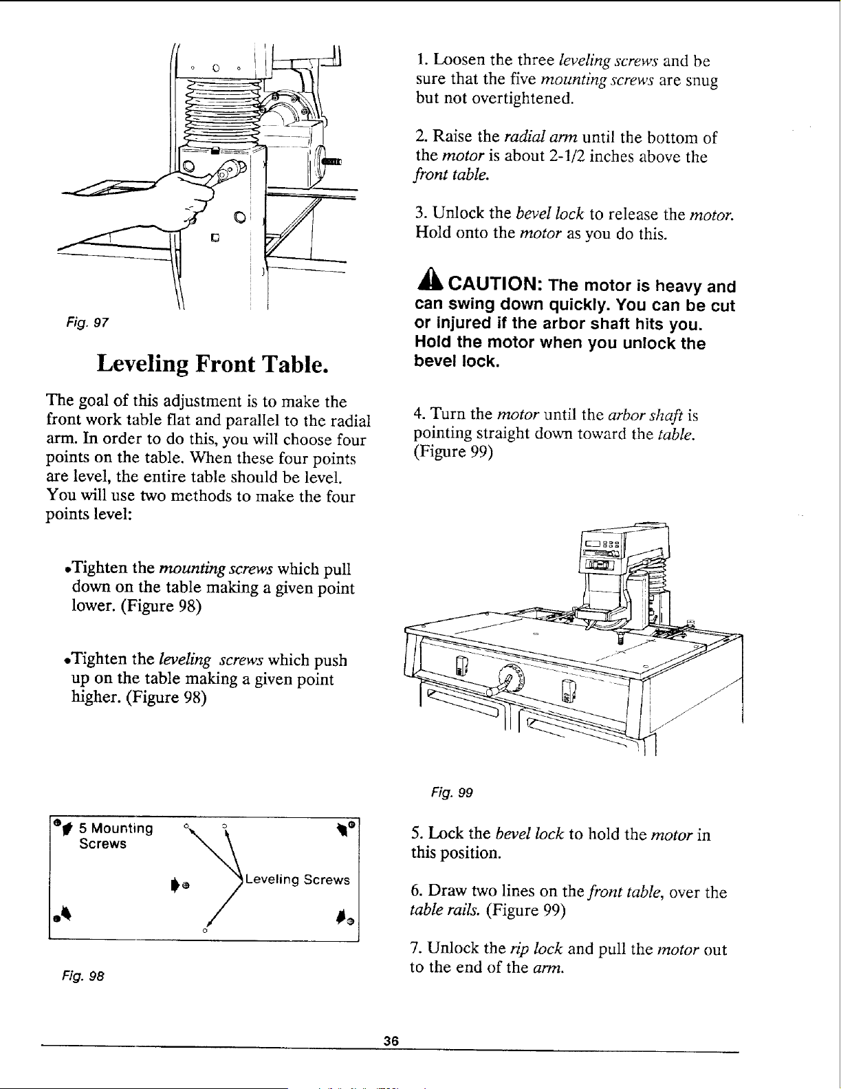
Fig. 97
Leveling Front Table.
The goal of this adjustment is to make the
front work table flat and parallel to the radial
arm. In order to do this, you will choose four
points on the table. When these four points
are level, the entire table should be level.
You will use two methods to make the four
points level:
1. Loosen the three leveling screws and be
sure that the five mounting screws are snug
but not overtightened.
2. Raise the radial arm until the bottom of
the motor is about 2-1/2 inches above the
front table.
3. Unlock the bevel lock to release the motor.
Hold onto the motor as you do this.
_1_ CAUTION: The motor is heavy and
can swing down quickly. You can be cut
or injured if the arbor shaft hits you.
Hold the motor when you unlock the
bevel lock.
4. Turn the motor until the arbor shaft is
pointing straight down toward the table.
(Figure 99)
.Tighten the mounting screws which pull
down on the table making a given point
lower. (Figure 98)
,Tighten the leveling screws which push
up on the table making a given point
higher. (Figure 98)
eli 5 Mounting ° ° _1!e
Screws __I_ Leveling Screws
• /
O
i
Fig. 98
Fig. 99
5. Lock the bevel lock to hold the motor in
this position.
6. Draw two lines on the front table, over the
table rails. (Figure 99)
7. Unlock the rip lock and pull the motor out
to the end of the arm.
36
8. Unlock the miter lock and swing the arm to
the right until the arbor shaft is over the right
line.
9. Mark the point on the line under the cen-
ter of the arbor shaft.
10. Move the arm and motor until the arbor
shaft is over the right line at the rear of the
front table.
11. Mark the point on the line under the cen-
ter of the arbor shaft.
12. Repeat steps 7-11 on the left side.
13. Label the points A, B, C, and D.
14. Move the arbor shaft over these points
again, and measure the distance between the
table and the bottom of the arbor shaft at
each. Do not change the elevation of the arm
as you move from point to point.
15. Determine which point has the largest dis-
tance between the table and the arborshaft.
This is the lowest point.
16. Move the arbor shaft over the lowest
point.
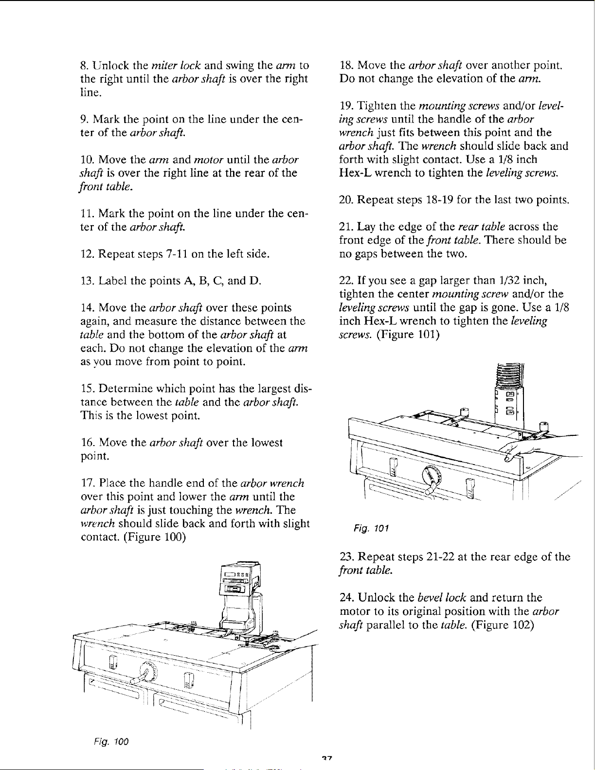
17. Place the handle end of the arbor wrench
over this point and lower the arm until the
arbor shaft is just touching the wrench. The
wrench should slide back and forth with slight
contact. (Figure 100)
18. Move the arbor shaft over another point.
Do not change the elevation of the arm.
19. Tighten the mounting screws and/or level-
ing screws until the handle of the arbor
wrench just fits between this point and the
arbor shaft. The wrench should slide back and
forth with slight contact. Use a 1/8 inch
Hex-L wrench to tighten the leveling screws.
20. Repeat steps 18-19 for the last two points.
21. Lay the edge of the rear table across the
front edge of the front table. There should be
no gaps between the two.
22. If you see a gap larger than 1/32 inch,
tighten the center mounting screw and/or the
leveling screws until the gap is gone. Use a 1/8
inch Hex-L wrench to tighten the leveling
screws. (Figure 101)
Fig. 101
23. Repeat steps 21-22 at the rear edge of the
front table.
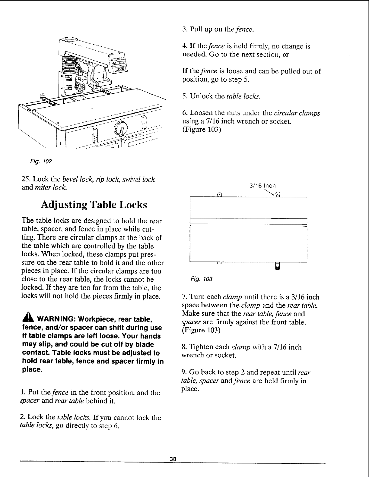
24. Unlock the bevel lock and return the
motor to its original position with the arbor
shaft parallel to the table. (Figure 102)
Fig. 100
_7
3. Pull up on the fence.
4. If the fence is held firmly, no change is
needed. Go to the next section, or
If the fence is loose and can be pulled out of
position, go to step 5.
5. Unlock the table locks.
6. Loosen the nuts under the circular clamps
using a 7/16 inch wrench or socket.
(Figure 103)
Fig. 102
25. Lock the bevel lock, rip lock, swivel lock
and miter lock.
Adjusting Table Locks
The table locks are designed to hold the rear
table, spacer, and fence in place while cut-
ting. There are circular clamps at the back of
the table which are controlled by the table
locks. When locked, these clamps put pres-
sure on the rear table to hold it and the other
pieces in place. If the circular clamps are too
close to the rear table, the locks cannot be
locked, ff they are too far from the table, the
locks will not hold the pieces firmly in place.
WARNING: Workpiece, rear table,
fence, and/or spacer can shift during use
if table clamps are left loose. Your hands
may slip, and could be cut off by blade
contact. Table locks must be adjusted to
hold rear table, fence and spacer firmly in
place.
1. Put the fence in the front position, and the
spacer and rear table behind it.
2. Lock the table locks. If you cannot lock the
table locks, go directly to step 6.
3/16 Inch
Fig. 103
7. Turn each clamp until there is a 3/16 inch
space between the clamp and the rear table.
Make sure that the rear table, fence and
spacer are firmly against the front table.
(Figure 103)
8. Tighten each clamp with a 7/16 inch
wrench or socket.
9. Go back to step 2 and repeat until rear
table, spacer and fence are held firmly in
place.
38
Squaring Crosscut Travel
The blade must travel perpendicular to the
fence along the radial arm in order for
crosscuts to be accurate. If the radial arm is
not perpendicular to the fence, there will be
a slight miter angle in all crosscuts.
_lb WARNING: Plugging in the saw
during alignment can result in your
fingers, hands, or arm being cut off from
blade contact. Do not plug in the saw at
any time during alignment. The saw
should only be plugged in when it is to be
used.
1. Place the radial arm in the 0° miter posi-
tion and lock the miter lock.
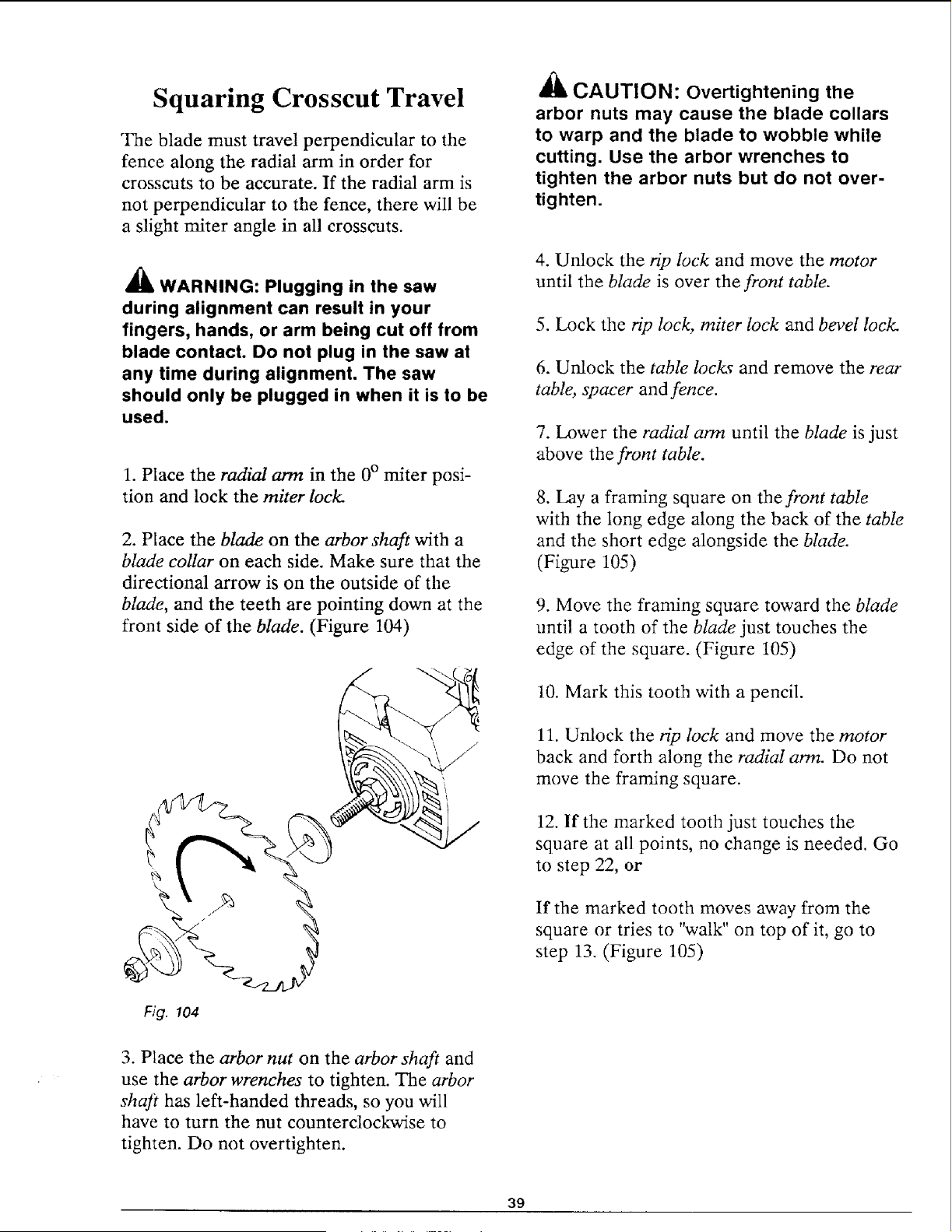
2. Place the blade on the arbor shaft with a
blade collar on each side. Make sure that the
directional arrow is on the outside of the
blade, and the teeth are pointing down at the
front side of the blade. (Figure 104)
//
_1_ CAUTION: Overtightening the
arbor nuts may cause the blade collars
to warp and the blade to wobble while
cutting. Use the arbor wrenches to
tighten the arbor nuts but do not over-
tighten.
4. Unlock the rip lock and move the motor
until the blade is over the front table.
5. Lock the rip lock, miter lock and bevel lock.
6. Unlock the table loc!_ and remove the rear
table, spacer and fence.
7. Lower the radial arm until the blade is just
above the front table.
8. Lay a framing square on the front table
with the long edge along the back of the table
and the short edge alongside the blade.
(Figure 105)
9. Move the framing square toward the blade
until a tooth of the blade just touches the
edge of the square. (Figure 105)
10. Mark this tooth with a pencil.
11. Unlock the rip lock and move the motor
back and forth along the radial arm. Do not
move the framing square.
12. If the marked tooth just touches the
square at all points, no change is needed. Go
to step 22, or
If the marked tooth moves away from the
square or tries to "walk" on top of it, go to
step 13. (Figure 105)
Fig. 104
3. Place the arbor nut on the arbor shaft and
use the arbor wrenches to tighten. The arbor
shaft has left-handed threads, so you will
have to turn the nut counterclockwise to
tighten. Do not overtighten.
39
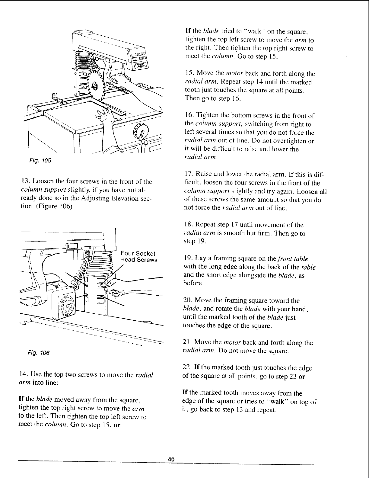
Fig. 105
13. Loosen the tour screws in the front of the
column support slightly, if you have not al-
ready done so in the Adjusting Elevation sec-
tion. (Figure 106)
f" j
Fig. 106
14. Use the top two screws to move the radial
arm into line:
If the blade moved away from the square,
tighten the top right screw to move the arm
to the left. Then tighten the top left screw to
meet the column. Go to step 15, or
If the blade tried to "walk" on the square,
tighten the top left screw to move the arm to
the right. Then tighten the top right screw to
meet the column. Go to step 15.
15. Move the motor back and forth along the
radial arm. Repeat step 14 until the marked
tooth just touches the square at all points.
Then go to step 16.
16. Tighten the bottom screws in the front of
the column support, switching from right to
left several times so that you do not force the
radial arm out of line. Do not overtighten or
it will be difficult to raise and lower the
radial arm.
17. Raise and lower the radial arm. If this is dif-
ficult, loosen the four screws in the front of the
column support slightly and try again. Loosen all
of these screws the same amount so that you do
not force the radial arm out of line.
18. Repeat step 17 until movement of the
radial arm is smooth but firm. Then go to
step 19.
19. Lay a framing square on the front table
with the long edge along the back of the table
and the short edge alongside the blade, as
before.
20. Move the framing square toward the
blade, and rotate the blade with your hand,
until the marked tooth of the blade just
touches the edge of the square.
2 I. Move the motor back and forth along the
radial arm. Do not move the square.
22. If the marked tooth just touches the edge
of the square at all points, go to step 23 or
If the marked tooth moves away fi'om the
edge of the square or tries to "walk" on top of
it, go back to step 13 and repeat.
4O
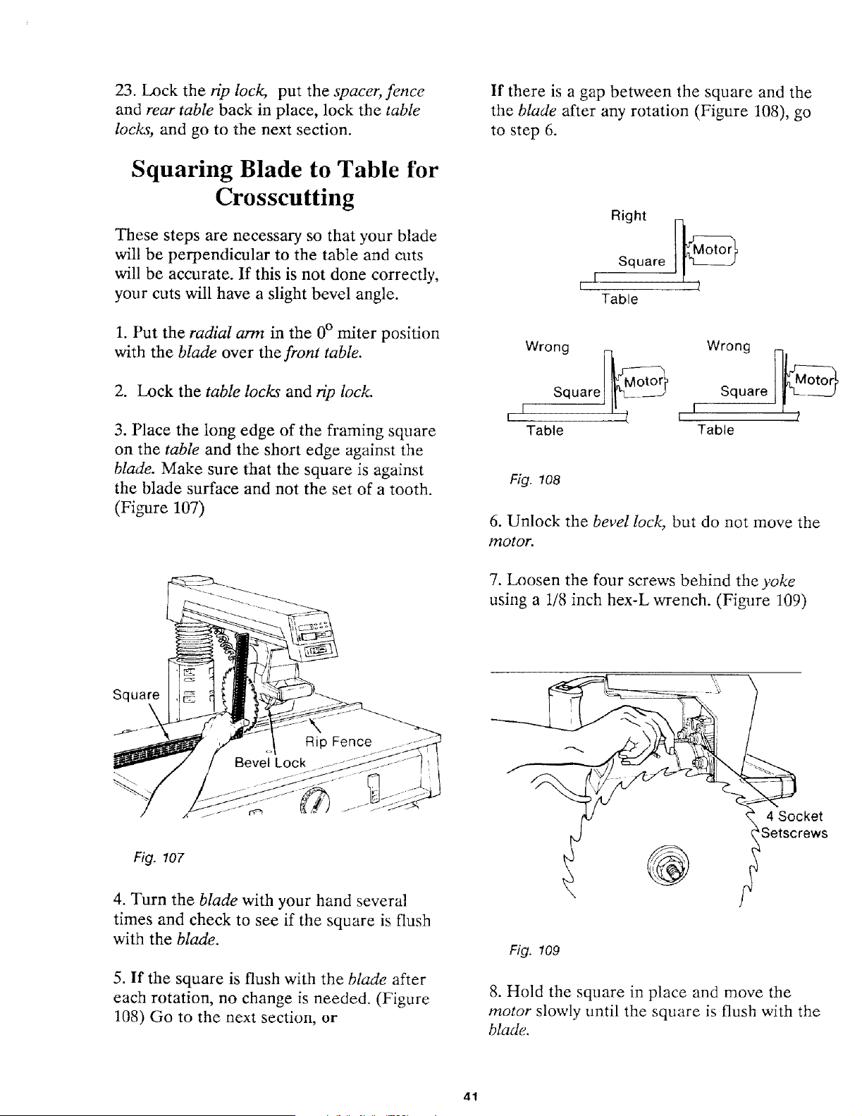
23. Lock the rip lock, put the spacer, fence
and rear table back in place, lock the table
locks, and go to the next section.
Squaring Blade to Table for
Crosscutting
These steps are necessary so that your blade
will be perpendicular to the table and cuts
will be accurate. If this is not done correctly,
your cuts will have a slight bevel angle.
1. Put the radial arm in the 0° miter position
with the blade over the front table.
2. Lock the table locks and gp lock.
3. Place the long edge of the framing square
on the table and the short edge against the
blade. Make sure that the square is against
the blade surface and not the set of a tooth.
(Figure 107)
If there is a gap between the square and the
the blade after any rotation (Figure 108), go
to step 6.
Right
r I Square t_
Table
Wrong _;___ Wrong )_
q Square
I S uare Motor r I /
Table Table
Fig. 108
6. Unlock the bevel lock, but do not move the
motor.
7. Loosen the four screws behind the yoke
using a 1/8 inch hex-L wrench. (Figure 109)
Square
Fig. 107
4. Turn the blade with your hand several
times and check to see if the square is flush
with the blade.
5. If the square is flush with the blade after
each rotation, no change is needed. (Figure
108) Go to the next section, or
@
4 Socket
'Setscrews
Fig. 109
8. Hold the square in place and move the
motor slowly until the square is flush with the
blade.
41
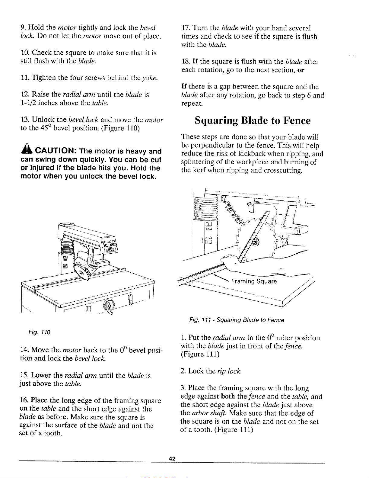
9. Hold the motor tightly and lock the bevel
lock. Do not let the motor move out of place.
10. Check the square to make sure that it is
still flush with the blade.
11. Tighten the four screws behind the yoke.
12. Raise the radial arm until the blade is
1-1/2 inches above the table.
13. Unlock the bevel lock and move the motor
to the 45 ° bevel position. (Figure 110)
CAUTION: The motor is heavy and
can swing down quickly. You can be cut
or injured il the blade hits you. Hold the
motor when you unlock the bevel lock.
17. Turn the blade with your hand several
times and check to see if the square is flush
with the blade.
18. If the square is flush with the blade after
each rotation, go to the next section, or
If there is a gap between the square and the
blade after any rotation, go back to step 6 and
repeat.
Squaring Blade to Fence
These steps are done so that your blade will
be perpendicular to the fence. This will help
reduce the risk of kickback when ripping, and
splintering of the workpiece and burning of
the kerf when ripping and crosscutting.
Fig. 110
14. Move the motor back to the 0 ° bevel posi-
tion and lock the bevel lock.
15. Lower the radial arm until the blade is
just above the table.
16. Place the long edge of the framing square
on the table and the short edge against the
blade as before. Make sure the square is
against the surface of the blade and not the
set of a tooth.
Fig. 111 - Squaring Blade to Fence
1. Put the radial arm in the 0 ° miter position
with the blade just in front of the fence.
(Figure 111)
2. Lock the rip lock.
3. Place the framing square with the long
edge against both the fence and the table, and
the short edge against the blade just above
the arbor shaft. Make sure that the edge of
the square is on the blade and not on the set
of a tooth. (Figure 111)
42
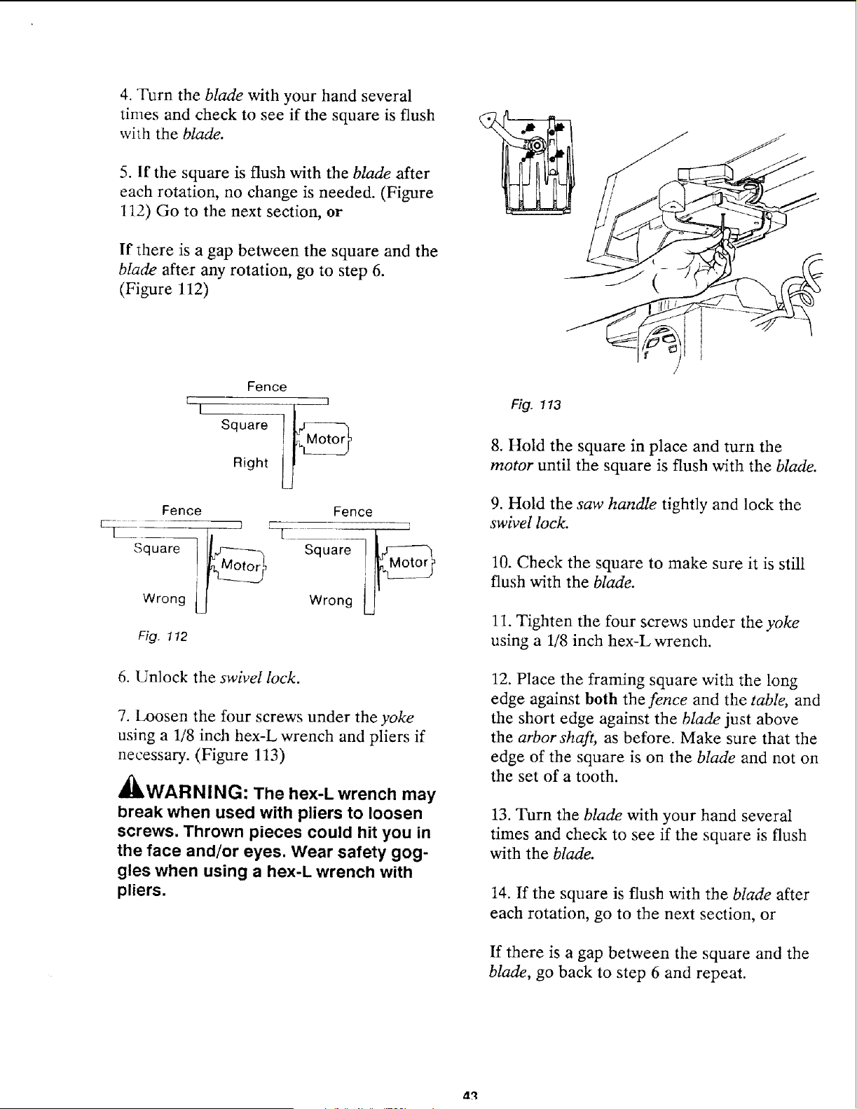
4. Turn the blade with your hand several
times and check to see if the square is flush
with the blade.
5. If the square is flush with the blade after
each rotation, no change is needed. (Figure
112) Go to the next section, or
If there is a gap between the square and the
blade after any rotation, go to step 6.
(Figure 112)
(
I
Fence
]
Square !_Right
Fence Fence
Square Squa
Wrong Wron 9
Fig. 1!2
6. Unlock the swivel lock.
7. Loosen the four screws under the yoke
using a 118 inch hex-L wrench and pliers if
necessary. (Figure 113)
_,WARNING: The hex-L wrench may
break when used with pliers to loosen
screws. Thrown pieces could hit you in
the face and/or eyes. Wear safety gog-
gles when using a hex-L wrench with
pliers.
Fig. 113
8. Hold the square in place and turn the
motor until the square is flush with the blade.
9. Hold the saw handle tightly and lock the
swivel lock.
10. Check the square to make sure it is still
flush with the blade.
11. Tighten the four screws under the yoke
using a 1/8 inch hex-L wrench.
12. Place the framing square with the long
edge against both the fence and the table, and
the short edge against the blade just above
the arbor shaft, as before. Make sure that the
edge of the square is on the blade and not on
the set of a tooth.
13. Turn the blade with your hand several
times and check to see if the square is flush
with the blade.
14. If the square is flush with the blade after
each rotation, go to the next section, or
If there is a gap between the square and the
blade, go back to step 6 and repeat.
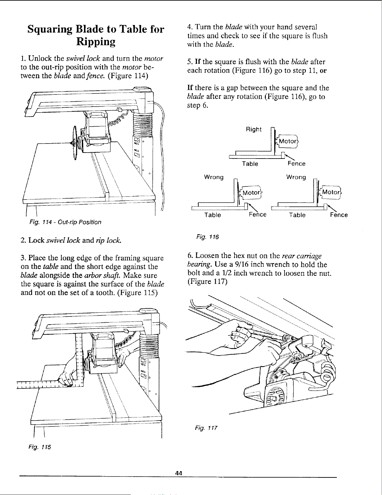
Squaring Blade to Table for
Ripping
1. Unlock the swivel lock and turn the motor
to the out-rip position with the motor be-
tween the blade and fence. (Figure 114)
Fig. 114 - Out-rip Position
2. Lock swivel lock and rip lock.
3. Place the long edge of the framing square
on the table and the short edge against the
blade alongside the arbor shaft. Make sure
the square is against the surface of the blade
and not on the set of a tooth. (Figure 115)
F_ I t I iii1,1_÷_,,
±lilll
/
Fig. 115
4. Turn the blade with your hand several
times and check to see if the square is flush
with the blade.
5. If the square is flush with the blade after
each rotation (Figure 116) go to step 11, or
If there is a gap between the square and the
blade after any rotation (Figure 116), go to
step 6.
Right [M_otor
t f R'-..
Table Fence
Wrong _ Wrong
I Table I' [_F_enc i I
e Table
n.,..
Fence
Fig. 116
6. Loosen the hex nut on the rear carriage
bearing. Use a 9/16 inch wrench to hold the
bolt and a 1/2 inch wrench to loosen the nut.
(Figure 117)
Fig. 117
44
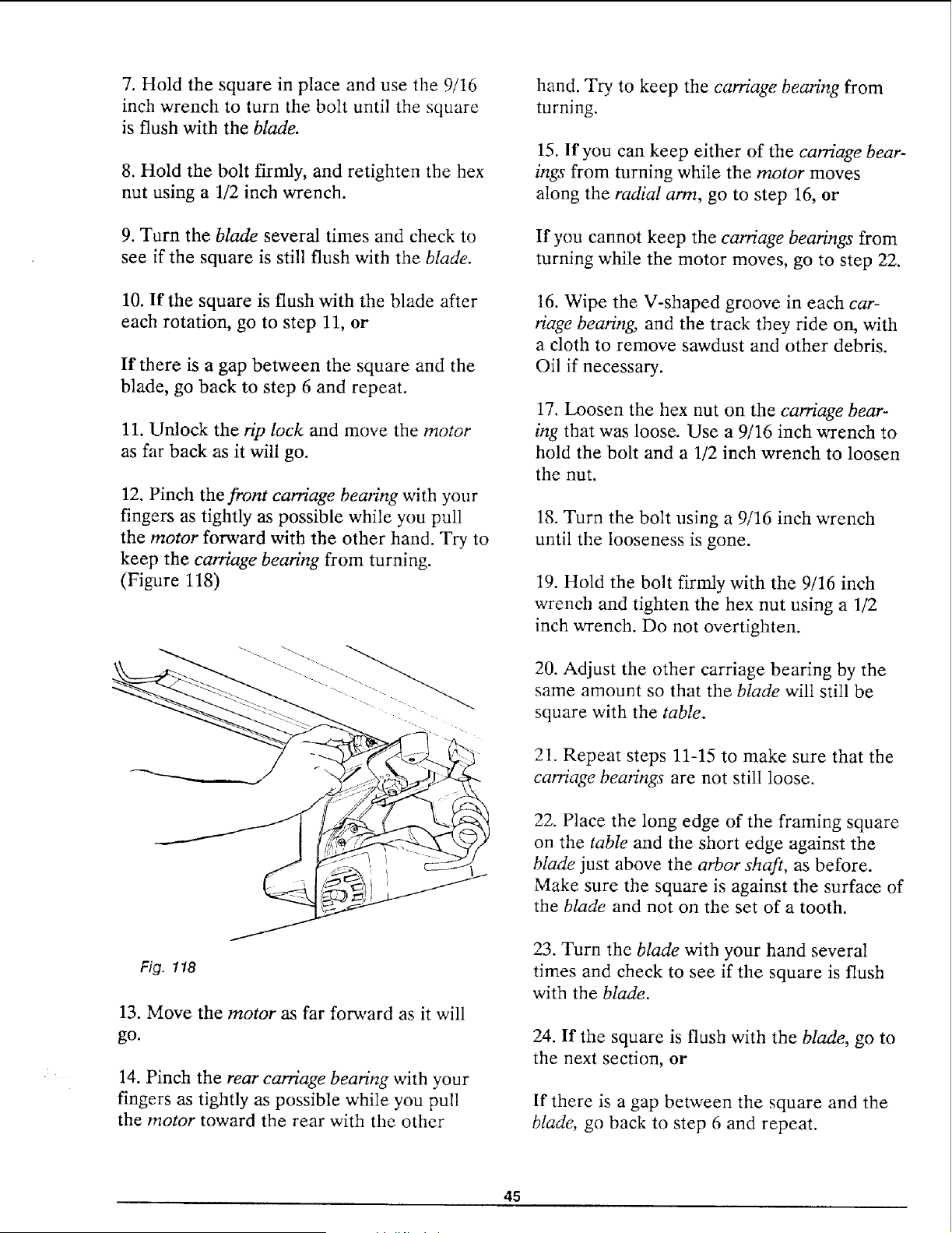
7. Hold the square in place and use the 9/16
inch wrench to turn the bolt until the square
is flush with the blade.
8. Hold the bolt firmly, and retighten the hex
nut using a 1/2 inch wrench.
9. Turn the blade several times and check to
see if the square is still flush with the blade.
10. If the square is flush with the blade after
each rotation, go to step 11, or
If there is a gap between the square and the
blade, go back to step 6 and repeat.
11. Unlock the rip lock and move the motor
as far back as it will go.
12. Pinch the front carriage bearing with your
fingers as tightly as possible while you pull
the motor forward with the other hand. Try to
keep the carriage bearing from turning.
(Figure 118)
Fig. 118
13. Move the motor as far forward as it will
go.
14. Pinch the rear carriage bearing with your
fingers as tightly as possible while you pull
the motor toward the rear with the other
hand. Try to keep the carriage bearing from
turning.
15. If you can keep either of the carriage bear-
ings from turning while the motor moves
along the radial arm, go to step 16, or
If you cannot keep the carriage bearings from
turning while the motor moves, go to step 22.
16. Wipe the V-shaped groove in each car-
riage beating, and the track they ride on, with
a cloth to remove sawdust and other debris.
Oil if necessary.
17. Loosen the hex nut on the carriage bear-
ing that was loose. Use a 9/16 inch wrench to
hold the bolt and a 1/2 inch wrench to loosen
the nut.
18. Turn the bolt using a 9/16 inch wrench
until the looseness is gone.
19. Hold the bolt firmly with the 9/16 inch
wrench and tighten the hex nut using a 1/2
inch wrench. Do not overtighten.
20. Adjust the other carriage bearing by the
same amount so that the blade will still be
square with the table.
21. Repeat steps 11-15 to make sure that the
carriage bearings are not still loose.
22. Place the long edge of the framing square
on the table and the short edge against the
blade just above the arbor shaft, as before.
Make sure the square is against the surface of
the blade and not on the set of a tooth.
23. Turn the blade with your hand several
times and check to see if the square is flush
with the blade.
24. If the square is flush with the blade, go to
the next section, or
If there is a gap between the square and the
blade, go back to step 6 and repeat.
45
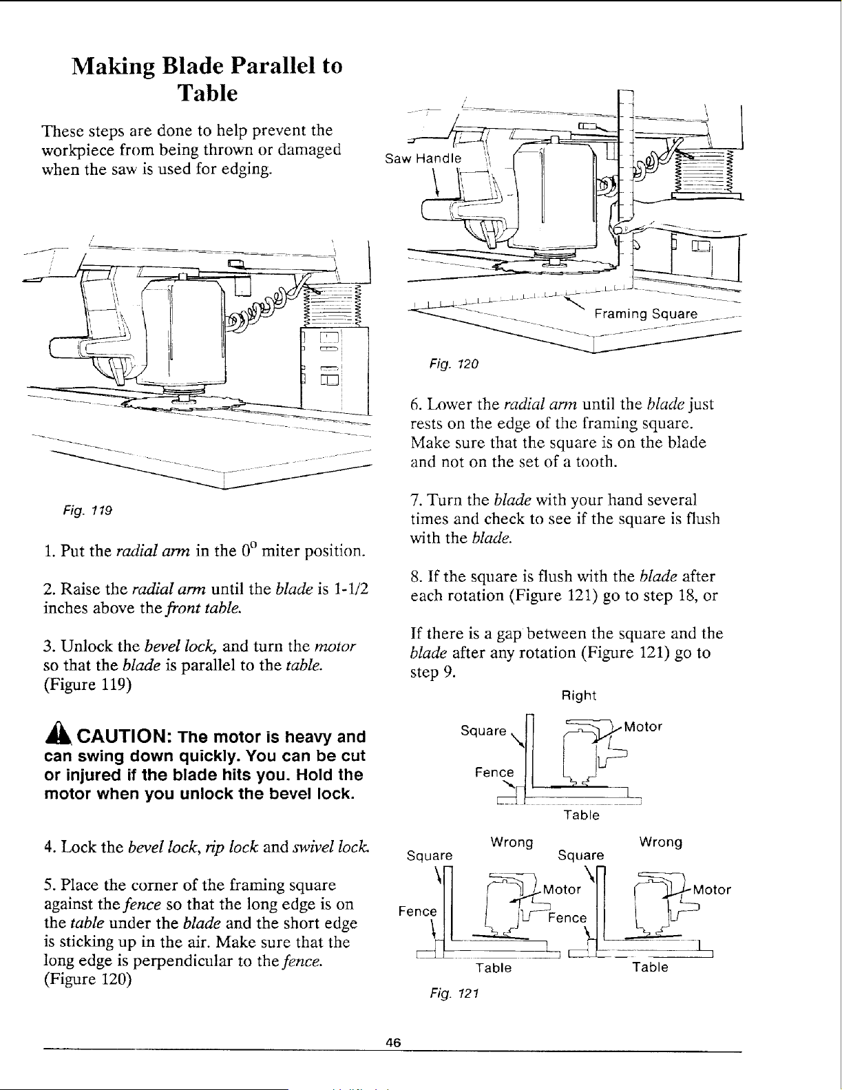
Making Blade Parallel to
Table
These steps are done to help prevent the
workpiece from being thrown or damaged
when the saw is used for edging.
Fig. 120
6. Lower the radial arm until the blade just
rests on the edge of the framing square.
Make sure that the square is on the blade
and not on the set of a tooth.
Fig. 119
1. Put the radial arm in the 0° miter position.
2. Raise the radial arm until the blade is 1-1/2
inches above the front table.
3. Unlock the bevel lock, and turn the motor
so that the blade is parallel to the table.
(Figure 119)
CAUTION: The motor is heavy and
can swing down quickly. You can be cut
or injured if the blade hits you. Hold the
motor when you unlock the bevel lock.
4. Lock the bevel lock, rip lock and swivel lock.
5. Place the comer of the framing square
against the fence so that the long edge is on
the table under the blade and the short edge
is sticking up in the air. Make sure that the
long edge is perpendicular to the fence.
(Figure 120)
7. Turn the blade with your hand several
times and check to see if the square is flush
with the blade.
8. If the square is flush with the blade after
each rotation (Figure 121) go to step 18, or
If there is a gap between the square and the
blade after any rotation (Figure 121) go to
step 9.
Right
Square, H _-_, Motor
Fence 1] L j 1J--
Table
Wrong Wrong
Square Square
\H _)_ Motor\_ (_f, f Motor
Table Table
Fig. 12!
46
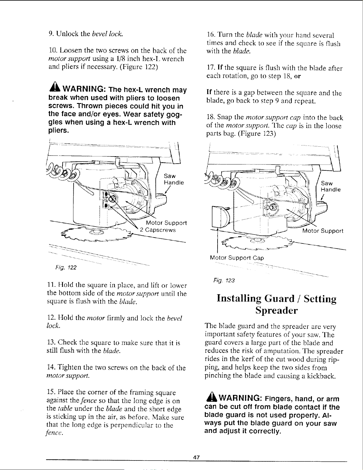
9. Unlock the bevel lock.
1(}. Loosen the two screws on the back of the
motor support using a 1/8 inch hex-I, wrench
and pliers if necessary. (Figure 122)
_lb WARNING: The hex-L wrench may
break when used with pliers to loosen
screws. Thrown pieces could hit you in
the face and/or eyes. Wear safety gog-
gles when using a hex-L wrench with
pliers.
I
Fiff. 122
11. Hold the square in place, and lift or lower
the bottom side of the motor support until the
square is flush with the blade.
12. Hold the motor firmly and lock the bevel
lock.
13. Check the square to make sure that it is
still flush with the blade.
14. Tighten the two screws on the back of the
motor support.
15. Place the corner of the flaming square
against the fence so that the long edge is on
the table under the blade and the short edge
is sticking up in the air, as before. Make sure
that the long edge is perpendicular to the
felTcc.
16. Turn the blade with your hand several
times and check to see if the square is flush
with the blade.
17. If the square is flush with the blade after
each rotation, go to step 18, or
If there is a gap between the square and the
blade, go back to step 9 and repeat.
18. Snap the motor support cap into the back
of the motor support. The cap is in the loose
parts bag. (Figure 123)
Saw
\ Handle
/
"-----_ __...J Motor Support
Motor Support Cap
Fig. 123
Installing Guard / Setting
Spreader
The blade guard and the spreader are very
important safety features of your saw. The
guard covers a large part of the blade and
reduces the risk of amputation. The spreader
rides in the kerf of the cut wood during rip-
ping, and helps keep the two sides from
pinching the blade and causing a kickback.
a'k A
4uLWARNINL_: Fingers, hand, or arm
can be cut off from blade contact if the
blade guard is not used properly. Al-
ways put the blade guard on your saw
and adjust it correctly.
47
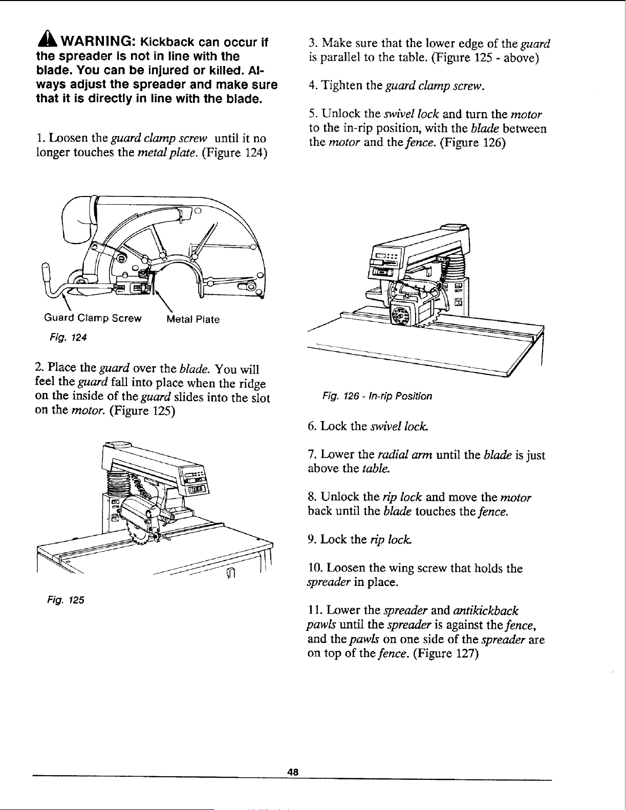
_lk WARNING: Kickback can occur if
the spreader is not in line with the
blade. You can be injured or killed. Al-
ways adjust the spreader and make sure
that it is directly in line with the blade.
1. Loosen the guard clamp screw until it no
longer touches the metalplate. (Figure 124)
3. Make sure that the lower edge of the guard
is parallel to the table. (Figure 125 - above)
4. Tighten the guard clamp screw.
5. Unlock the swivel lock and turn the motor
to the in-rip position, with the blade between
the motor and the fence. (Figure 126)
Guard Clamp Screw
Fig. 124
Metal Plate
2. Place the guard over the blade. You will
feel the guard fall into place when the ridge
on the inside of the guard slides into the slot
on the motor. (Figure 125)
Fig. 126- In-rip Position
6. Lock the swivel lock.
7. Lower the radial arm until the blade is just
above the table.
Fig. 125
8. Unlock the rip lock and move the motor
back until the blade touches the fence.
9. Lock the @ lock.
10. Loosen the wing screw that holds the
spreader in place.
11. Lower the spreader and antikickback
pawls until the spreader is against the fence,
and the pawls on one side of the spreader are
on top of the fence. (Figure 127)
48
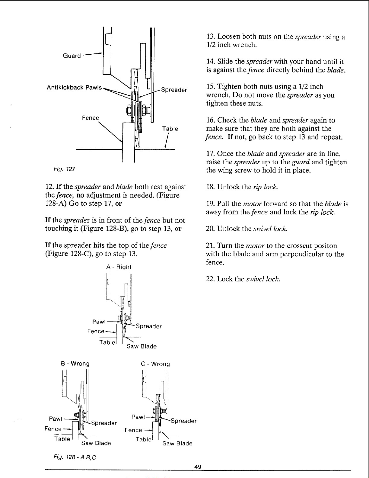
Guard
Antikickback Pawls
Spreader
Fence
Table
/
Fig. 127
12. If the spreader and blade both rest against
the fence, no adjustment is needed. (Figure
128-A) Go to step 17, or
If the spreader is in front of the fence but not
touching it (Figure 128-B), go to step 13, or
If the spreader hits the top of the fence
(Figure 128-C), go to step 13.
A- Right
Pawl
FenC_a_le
-Spreader
Saw Blade
13. Loosen both nuts on the spreader using a
1/2 inch wrench.
14. Slide the spreader with your hand until it
is against the fence directly behind the blade.
15. Tighten both nuts using a 1/2 inch
wrench. Do not move the spreader as you
tighten these nuts.
16. Check the blade and spreader again to
make sure that they are both against the
fence. If not, go back to step 13 and repeat.
17. Once the blade and spreader are in line,
raise the spreader up to the guard and tighten
the wing screw to hold it in place.
18. Unlock the rip lock.
19. Pull the motor forward so that the blade is
away from the fence and lock the rip lock.
20. Unlock the swivel lock.
21. Turn the motor to the crosscut positon
with the blade and arm perpendicular to the
fence.
22. Lock the swivel lock
B - Wron(
Pawl
Fence _ -Spreader
T-able I
Saw Blade
Fig. 128 - A,B,C
C - Wrong
Pawl-._ (
Fence
Table
"'Spreader
Saw Blade
49
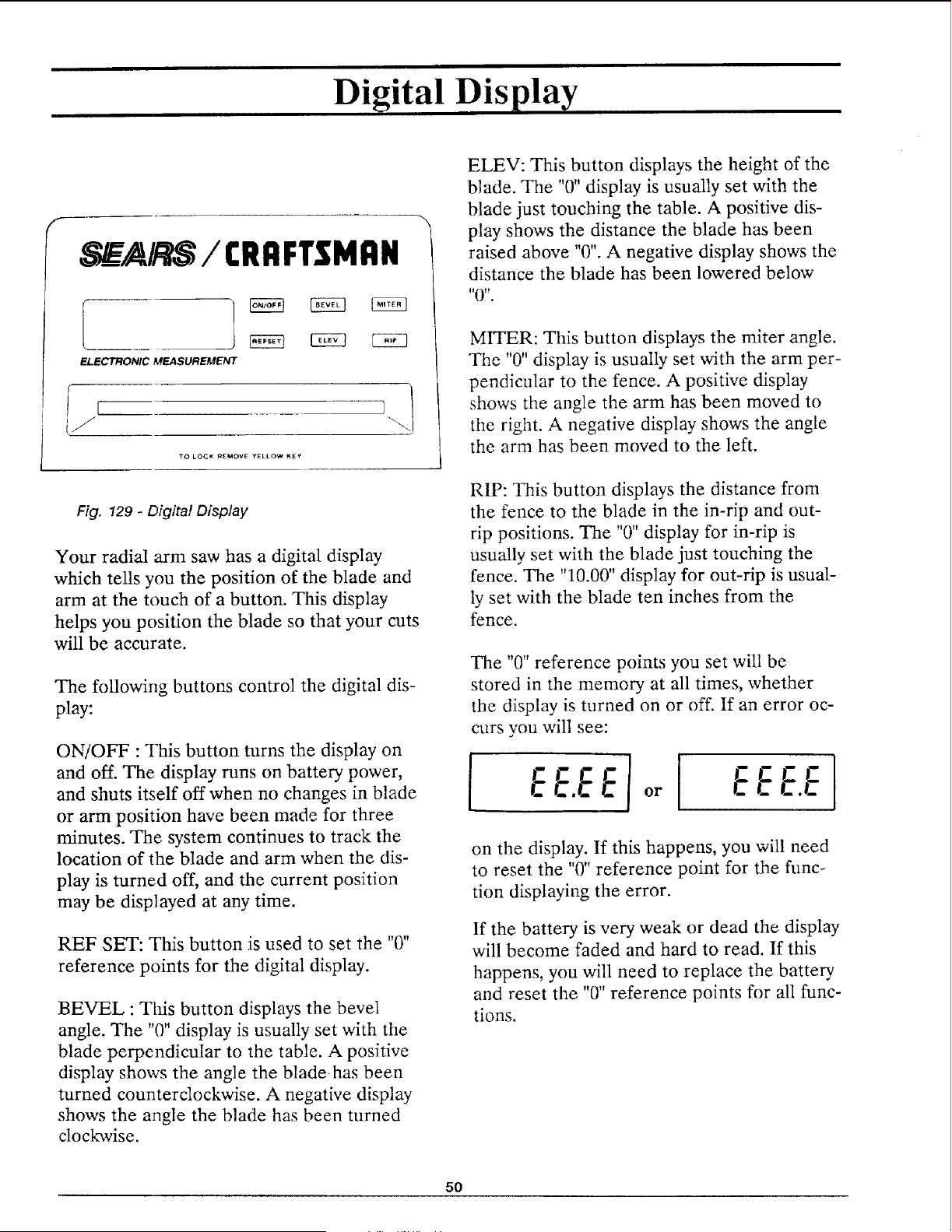
Digital Display
_A/RS / CRI1FT$1dRN
ELECTRONIC MEASUREMENT
TO LOCK R_MOVE YELLOW KEY
Fig. 129 - Dig#al Display
Your radial arm saw has a digital display
which tells you the position of the blade and
arm at the touch of a button. This display
helps you position the blade so that your cuts
will be accurate.
The following buttons control the digital dis-
play:
ON/OFF : This button turns the display on
and off. The display runs on battery power,
and shuts itself off when no changes in blade
or arm position have been made for three
minutes. The system continues to track the
location of the blade and arm when the dis-
play is turned off, and the current position
may be displayed at any time.
REF SET: This button is used to set the "0"
reference points for the digital display.
BEVEL : This button displays the bevel
angle. The "0" display is usually set with the
blade perpendicular to the table. A positive
display shows the angle the bladehas been
turned counterclockwise. A negative display
shows the angle the blade has been turned
cloc_vise.
ELEV: This button displays the height of the
blade. The "0" display is usually set with the
blade just touching the table. A positive dis-
play shows the distance the blade has been
raised above "0". A negative display shows the
distance the blade has been lowered below
I_0tt"
MITER: This button displays the miter angle.
The "0" display is usually set with the arm per-
pendicular to the fence. A positive display
shows the angle the arm has been moved to
the right. A negative display shows the angle
the arm has been moved to the left.
RIP: This button displays the distance from
the fence to the blade in the in-rip and out-
rip positions. The "0" display for in-rip is
usually set with the blade just touching the
fence. The "10.00" display for out-rip is usual-
ly set with the blade ten inches from the
fence.
The "0" reference points you set will be
stored in the memory at all times, whether
the display is turned on or off. If an error oc-
curs you will see:
f
EEE.E
on the display. If this happens, you will need
to reset the "0" reference point for the func-
tion displaying the error.
If the battery is very weak or dead the display
will become faded and hard to read. If this
happens, you will need to replace the battery
and reset the "0" reference points for all func-
tions.
5O
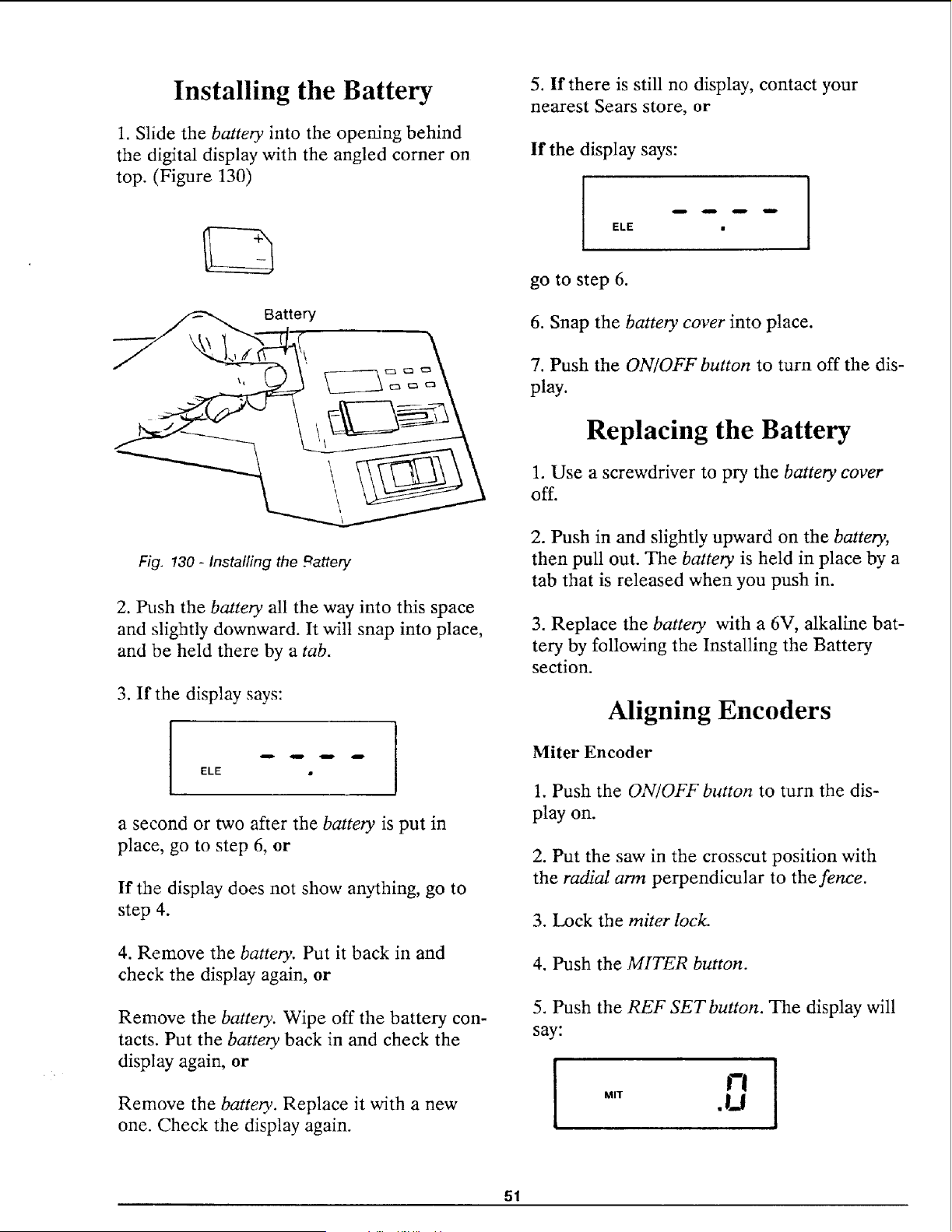
Installing the Battery
1. Slide the batter), into the opening behind
the digital display with the angled corner on
top. (Figure 130)
5. If there is still no display, contact your
nearest Sears store, or
If the display says:
Battery
ELE •
go to step 6.
6. Snap the battery cover into place.
7. Push the ON/OFF button to turn off the dis-
play.
Replacing the Battery
1. Use a screwdriver to pry the battery cover
off.
Fig. !30 - Installing the _attery
2. h_sh the battery all the way into this space
and slightly downward. It will snap into place,
and be held there by a tab.
3. If the display says:
ELE •
a second or two after the battery is put in
place, go to step 6, or
If the display does not show anything, go to
step 4.
4. Remove the battery. Put it back in and
check the display again, or
Remove the batter),. Wipe off the battery con-
tacts. Put the battery back in and check the
display again, or
Remove the battery. Replace it with a new
one. Check the display again.
2. Push in and slightly upward on the battery,
then pull out. The battery is held in place by a
tab that is released when you push in.
3. Replace the battery with a 6V, alkaline bat-
tery by following the Installing the Battery
section.
Aligning Encoders
Miter Encoder
1. Push the ON/OFF button to turn the dis-
play on.
2. Put the saw in the crosscut position with
the radial arm perpendicular to the fence.
3. Lock the miter lock.
4. Push the MITER button.
5. Push the REF SET button. The display will
say:
1
MIT
°i
.U
51
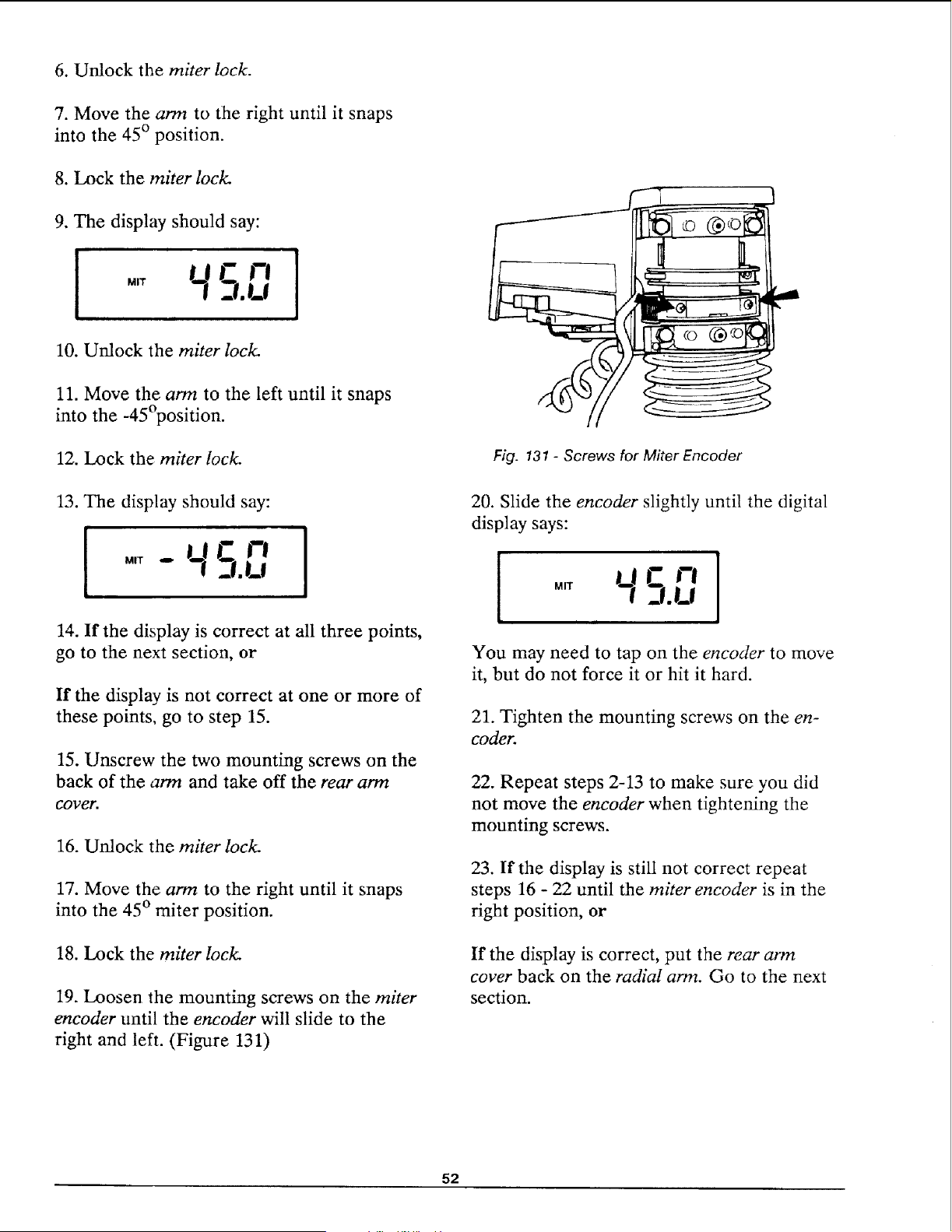
6. Unlock the miter lock.
7. Move the arm to the right until it snaps
into the 45 ° position.
8. Lock the miter lock.
9. The display should say:
!
10. Unlock the miter lock.
11. Move the arm to the left until it snaps
into the -45°position.
12. Lock the miter lock.
(
Fig. 131 - Screws for Miter Encoder
13. The display should say:
[ °._qc,-,
_!.U
!
14. If the display is correct at all three points,
go to the next section, or
If the display is not correct at one or more of
these points, go to step 15.
15. Unscrew the two mounting screws on the
back of the arm and take off the rear arm
COl)er.
16. Unlock the miter lock.
17. Move the arm to the right until it snaps
into the 45 ° miter position.
18. Lock the miter lock.
19. Loosen the mounting screws on the miter
encoder until the encoder will slide to the
right and left. (Figure 131)
20. Slide the encoder slightly until the digital
display says:
!
MIT
You may need to tap on the encoder to move
it, but do not force it or hit it hard.
21. Tighten the mounting screws on the en-
coder.
22. Repeat steps 2-13 to make sure you did
not move the encoder when tightening the
mounting screws.
23. If the display is still not correct repeat
steps 16 - 22 until the miter encoder is in the
right position, or
If the display is correct, put the rear arm
cover back on the radial arm. Go to the next
section.
52
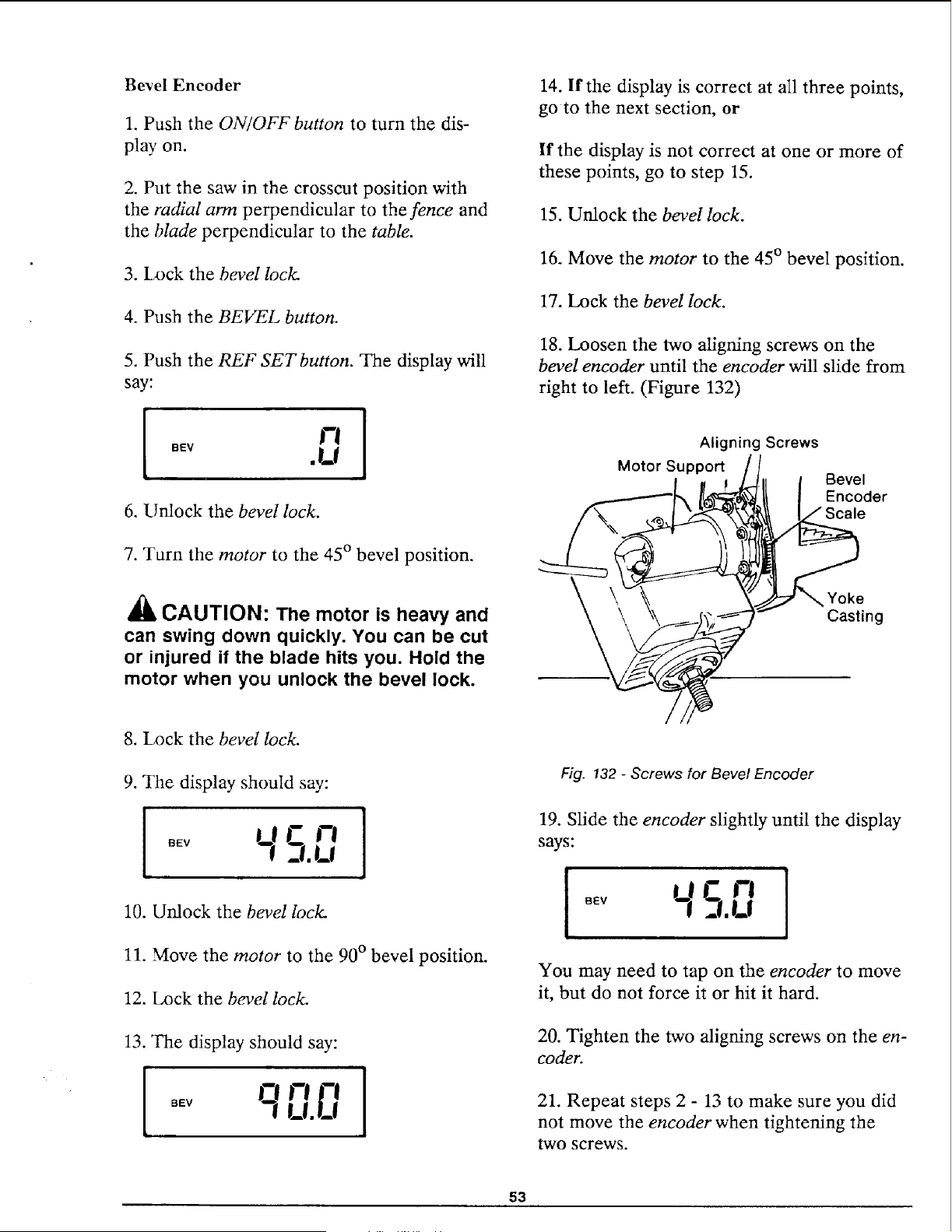
Bevel Encoder
1. Push the ON/OFF button to turn the dis-
play on.
2. Put the saw in the crosscut position with
the radial arm perpendicular to the fence and
the blade perpendicular to the table.
3. Lock the bevel lock.
4. Push the BEVEL button.
5. Push the REF SETbutton. The display will
say:
6. Unlock the bevel lock.
7. Turn the motor to the 45 ° bevel position.
_lb CAUTION: The motor is heavy and
can swing down quickly. You can be cut
or injured if the blade hits you. Hold the
motor when you unlock the bevel lock.
14. If the display is correct at all three points,
go to the next section, or
If the display is not correct at one or more of
these points, go to step 15.
15. Unlock the bevel lock.
16. Move the motor to the 45 ° bevel position.
17. Lock the bevel lock.
18. Loosen the two aligning screws on the
bevel encoder until the encoder will slide from
right to left. (Figure 132)
Aligning Screws
Motor Support
Bevel
Encoder
Scale
Yoke
Casting
8. Lock the bevel lock.
9. The display should say:
I I
10. Unlock the bevel lock.
11. Move the motor to the 90 ° bevel position.
12. Lock the bevel lock.
13. The display should say:
I q,-,,-,I
I_1,!_!
Fig. 132 - Screws for Bevel Encoder
19. Slide the encoder slightly until the display
says:
=!.U
You may need to tap on the encoder to move
it, but do not force it or hit it hard.
20. Tighten the two aligning screws on the en-
coder.
21. Repeat steps 2 - 13 to make sure you did
not move the encoder when tightening the
two screws.
53
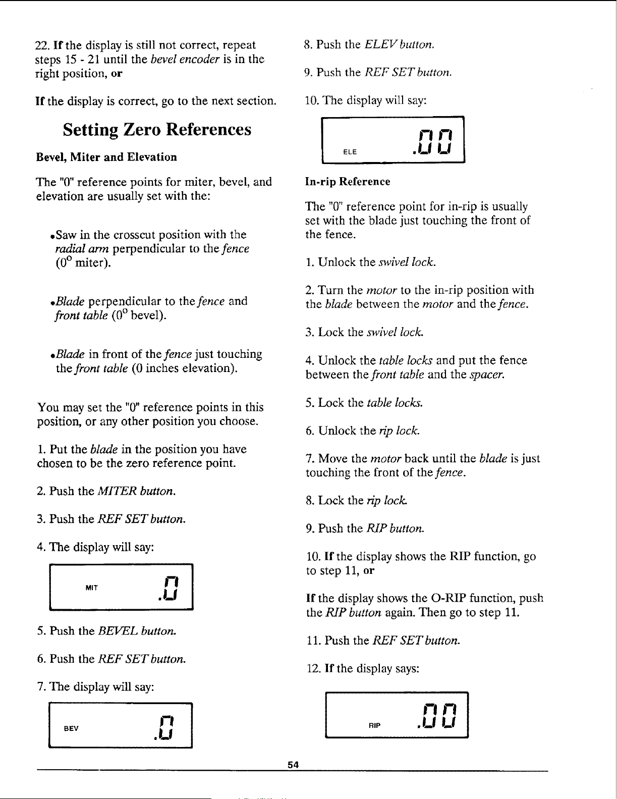
22. If the display is still not correct, repeat
steps 15 - 21 until the bevel encoder is in the
right position, or
8. Push the ELEVbutton.
9. Push the REF SET button.
If the display is correct, go to the next section.
Setting Zero References
Bevel, Miter and Elevation
The "0" reference points for miter, bevel, and
elevation are usually set with the:
• Saw in the crosscut position with the
radial arm perpendicular to the fence
(0 ° miter).
10. The display will say:
In-rip Reference
The "0" reference point for in-rip is usually
set with the blade just touching the front of
the fence.
1. Unlock the swivel lock.
•Blade perpendicular to the fence and
front table (0 ° bevel).
,Blade in front of the fence just touching
the front table (0 inches elevation).
2. Turn the motor to the in-rip position with
the blade between the motor and the fence.
3. Lock the swivel lock.
4. Unlock the table locks and put the fence
between the front table and the spacer.
You may set the "0" reference points in this
position, or any other position you choose.
1. Put the blade in the position you have
chosen to be the zero reference point.
2. Push the MITER button.
3. Push the REF SET button.
5. Lock the table locks.
6. Unlock the rip lock.
7. Move the motor back until the blade is just
touching the front of the fence.
8. Lock the rip lock.
9. Push the RIP button.
4. The display will say:
i " 0i
5. Push the BEVEL button.
10. If the display shows the RIP function, go
to step 11, or
If the display shows the O-RIP function, push
the RIP button again. Then go to step 11.
11. Push the REF SETbutton.
6. Push the REF SET button.
12. If the display says:
7. The display will say:
1 ! [ !
I-!
f"l .,0 .U U
BEV • _,j
54
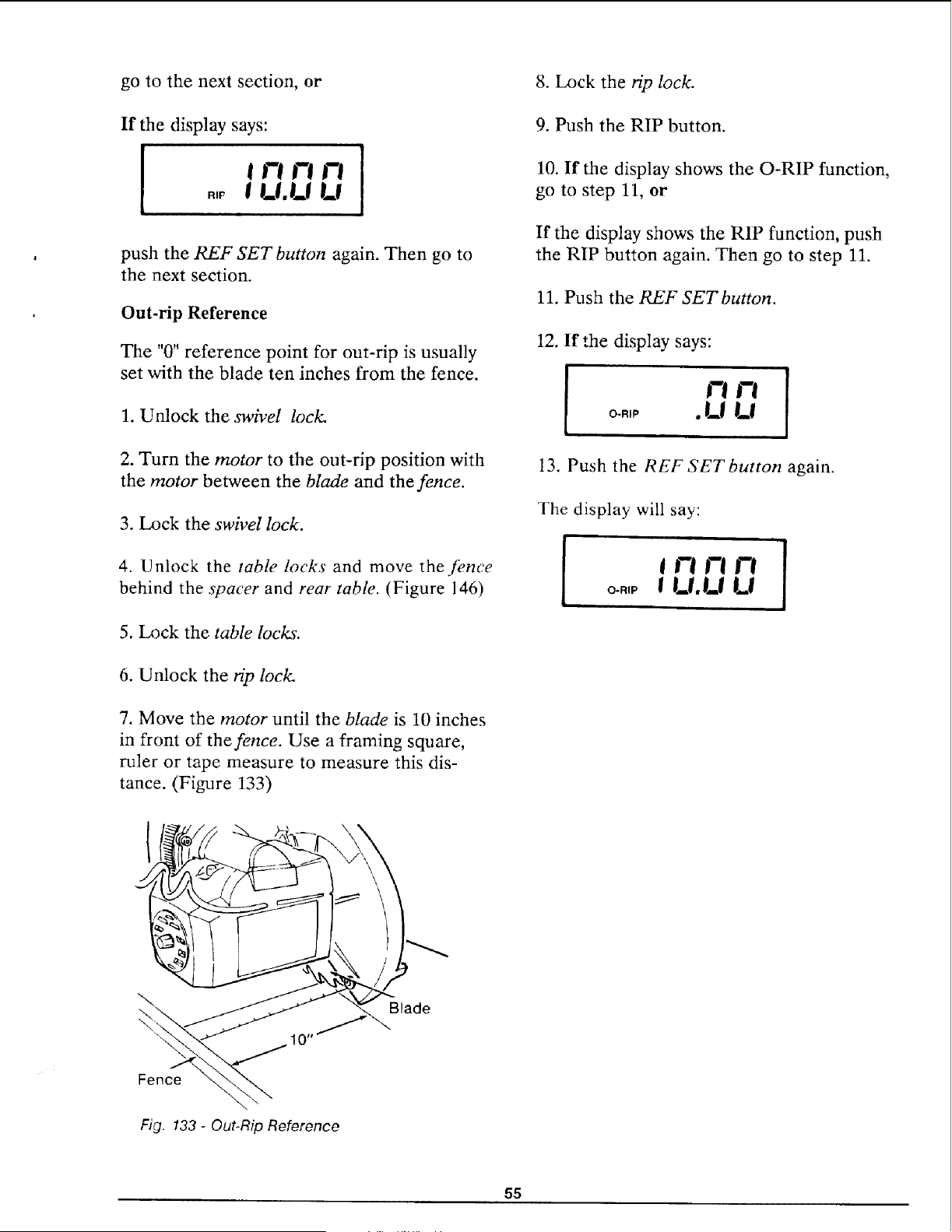
go to the next section, or
If the display says:
!
t Yi I-! I-!
.,_ I I_l.l_l I_l
1
push the REF SET button again. Then go to
the next section.
Out-rip Reference
The "0" reference point for out-rip is usually
set with the blade ten inches from the fence.
1. Unlock the swivel lock.
2. Turn the motor to the out-rip position with
the motor between the blade and the fence.
3. Lock the swivel lock.
4. Unlock the table locks and move the fence
behind the spacer and rear table. (Figure 146)
5. Lock the table locks.
8. Lock the rip lock.
9. Push the RIP button.
10. If the display shows the O-RIP function,
go to step 11, or
If the display shows the RIP function, push
the RIP button again. Then go to step 11.
11. Push the REF SETbutton.
12. If the display says:
1 '-"-'I
13. Push the REF SET button again.
The display will say:
i
l "-'n°1
o..,p ! t_l.t.I I_!
6. Unlock the ffp lock.
7. Move the motor until the blade is 10 inches
in front of the fence. Use a framing square,
ruler or tape measure to measure this dis-
tance. (Figure 133)
\
Blade
10-/
Fence
\
Fig. 133 - Out-Rip Reference
55
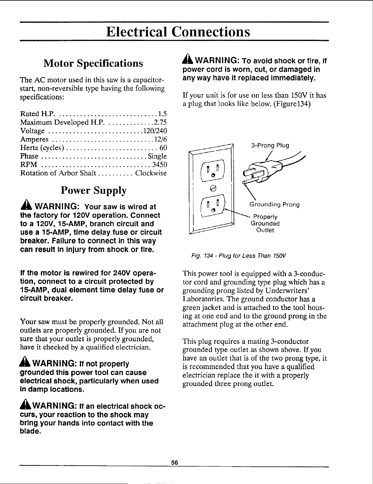
Electrical Connections
Motor Specifications
The AC motor used in this saw is a capacitor-
start, non-reversible type having the following
specifications:
Rated H.P ............................. 1.5
Maximum Developed H.P .............. 2.75
Voltage ........................... 120/240
Amperes ............................. 12/6
Hertz (cycles) .......................... 60
Phase .............................. Single
RPM ............................... 3450
Rotation of Arbor Shaft .......... Clockwise
Power Supply
WARNING: Your saw is wired at
the factory for 120V operation. Connect
to a 120V, 15-AMP, branch circuit and
use a 15-AMP, time delay fuse or circuit
breaker. Failure to connect in this way
can result in injury from shock or fire.
If the motor is rewired for 240V opera-
tion, connect to a circuit protected by
15-AMP, dual element time delay fuse or
circuit breaker.
Your saw must be properly grounded. Not all
outlets are properly grounded. If you are not
sure that your outlet is properly grounded,
have it checked by a qualified electrician.
WARNING: If not properly
grounded this power tool can cause
electrical shock, particularly when used
in damp locations.
41LWARNIN(3: If an electrical shock oc-
curs, your reaction to the shock may
bring your hands into contact with the
blade.
_I_WARNING: To avoid shock or fire, if
power cord is worn, cut, or damaged in
any way have it replaced immediately.
If your unit is for use on less than 150V it has
a plug that looks like below. (Figure134)
O
3-Prong Plug
Grounding Prong
Properly
Grounded
Outlet
Fig. 134 - Plug for Less Than 150V
This power tool is equipped with a 3-conduc-
tor cord and grounding type plug which has a
grounding prong listed by Underwriters'
Laboratories. The ground conductor has a
green jacket and is attached to the tool hous-
ing at one end and to the ground prong in the
attachment plug at the other end.
This plug requires a mating 3-conductor
grounded type outlet as shown above. If you
have an outlet that is of the two prong type, it
is recommended that you have a qualified
electrician replace the it with a properly
grounded three prong outlet.
56
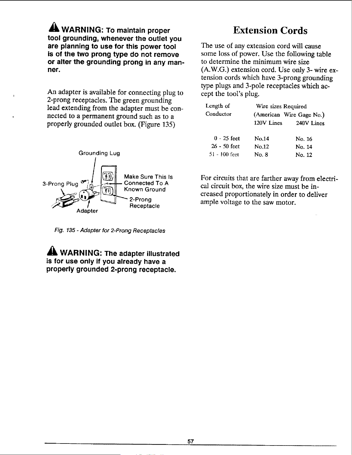
_k
AnalWARNING: To maintain proper
tool grounding, whenever the outlet you
are planning to use for this power tool
is of the two prong type do not remove
or alter the grounding prong in any man-
ner.
An adapter is available for connecting plug to
2-prong receptacles. The green grounding
lead extending from the adapter must be con-
nected to a permanent ground such as to a
properly grounded outlet box. (Figure 135)
Grounding Lug
3-Prong Plug o,"
_Make Sure This Is
Ir._-,L_ Connected To A
,__ _! _L Kn°wn Gr°und
_ 2-Prong
Receptacle
Adapter
Extension Cords
The use of any extension cord will cause
some loss of power. Use the following table
to determine the minimum wire size
(A.W.G.) extension cord. Use only 3- wire ex-
tension cords which have 3-prong grounding
type plugs and 3-pole receptacles which ac-
cept the tool's plug.
Length of
Conductor
Wire sizes Required
(American Wire Gage No.)
120V Lines 240V Lines
0 - 25 feet No.14 No. 16
26 - 50 feet No.12 No. 14
51 - 100 feet No. 8 No. 12
For circuits that are farther away from electri-
cal circuit box, the wire size must be in-
creased proportionately in order to deliver
ample voltage to the saw motor.
Fig. 135 - Adapter for 2-Prong Receptacles
_ib WARNING: The adapter illustrated
is for use only if you already have a
properly grounded 2-prong receptacle.
57
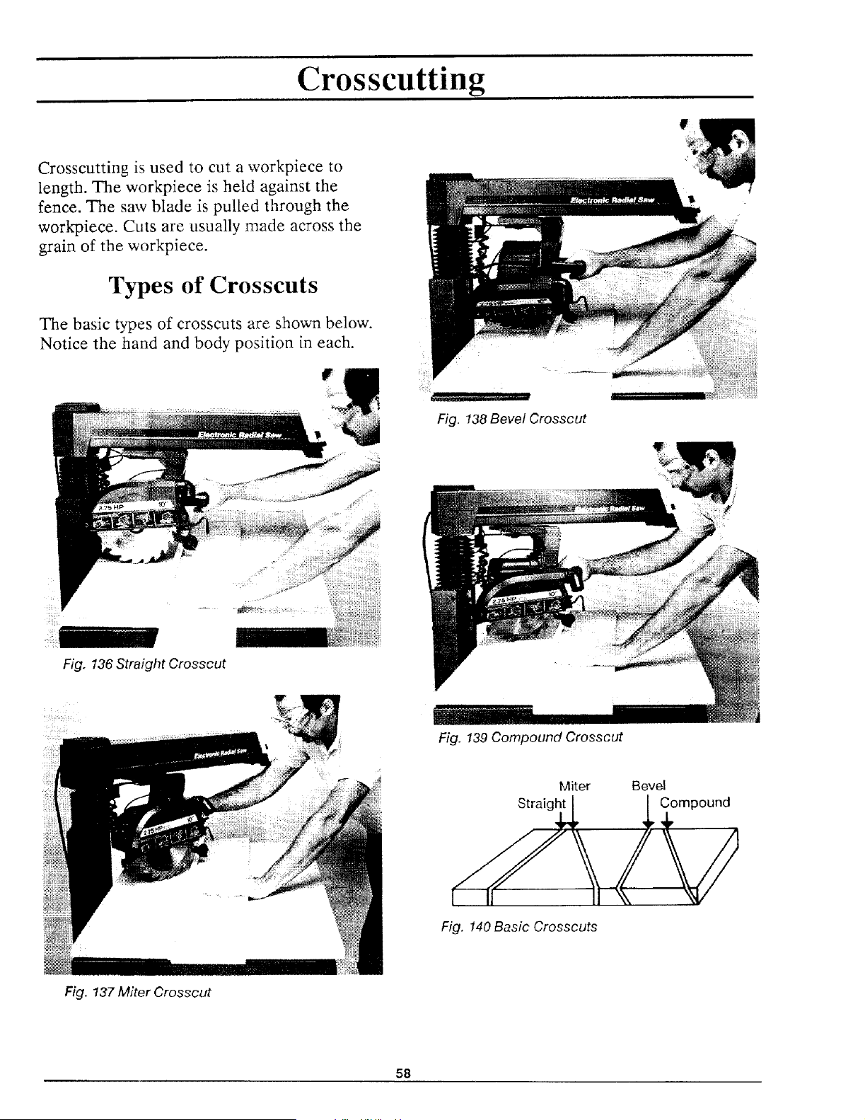
Crosscutting
r
Crosscutting is used to cut a workpiece to
length. The work_iece is held against the
fence. The saw blade is pulled through the
workpiece. Cuts are usually made across the
grain of the workpiece.
Types of Crosscuts
The basic types of crosscuts are shown below.
Notice the hand and body position in each.
Fig. 136 Straight Crosscut
Fig. 138 Bevel Crosscut
Fig. 139 Compound Crosscut
Miter
Straight
Fig. 140 Basic Crosscuts
Bevel
Compound
Fig. 137 Miter Crosscut
58
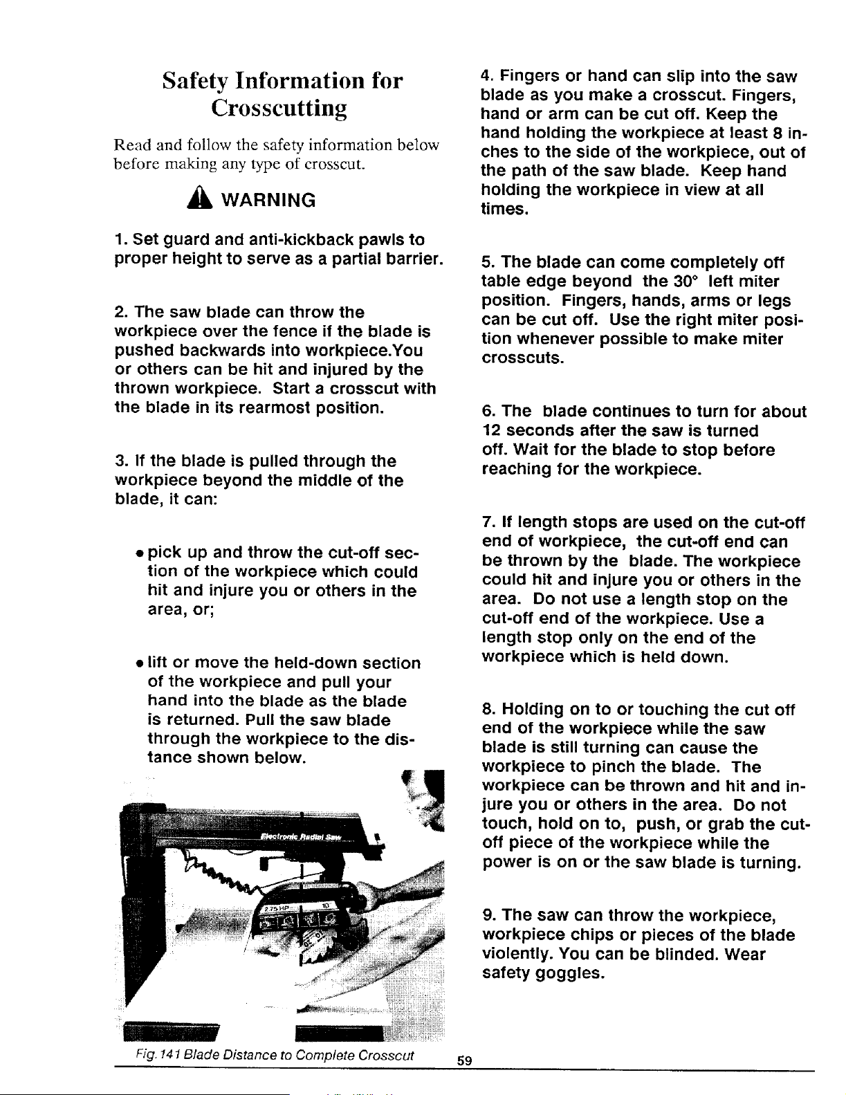
Safety Information for
Crosscutting
Read and follow the safety information below
before making any type of crosscut.
4_, WARNING
1. Set guard and anti-kickback pawls to
proper height to serve as a partial barrier.
2. The saw blade can throw the
workpiece over the fence if the blade is
pushed backwards into workpiece.You
or others can be hit and injured by the
thrown workpiece. Start a crosscut with
the blade in its rearmost position.
3. If the blade is pulled through the
workpiece beyond the middle of the
blade, it can:
= pick up and throw the cut-off sec-
tion of the workpiece which could
hit and injure you or others in the
area, or;
• lift or move the held-down section
of the workpiece and pull your
hand into the blade as the blade
is returned. Pull the saw blade
through the workpiece to the dis-
tance shown below.
Fig. 141 Blade DNtance to Complete Crosscut
59
4. Fingers or hand can slip into the saw
blade as you make a crosscut. Fingers,
hand or arm can be cut off. Keep the
hand holding the workpiece at least 8 in-
ches to the side of the workpiece, out of
the path of the saw blade. Keep hand
holding the workpiece in view at all
times.
5. The blade can come completely off
table edge beyond the 30 ° left miter
position. Fingers, hands, arms or legs
can be cut off. Use the right miter posi-
tion whenever possible to make miter
crosscuts.
6. The blade continues to turn for about
12 seconds after the saw is turned
off. Wait for the blade to stop before
reaching for the workpiece.
7. If length stops are used on the cut-off
end of workpiece, the cut-off end can
be thrown by the blade. The workpiece
could hit and injure you or others in the
area. Do not use a length stop on the
cut-off end of the workpiece. Use a
length stop only on the end of the
workpiece which is held down.
8. Holding on to or touching the cut off
end of the workpiece while the saw
blade is still turning can cause the
workpiece to pinch the blade. The
workpiece can be thrown and hit and in-
jure you or others in the area. Do not
touch, hold on to, push, or grab the cut-
off piece of the workpiece while the
power is on or the saw blade is turning.
9. The saw can throw the workpiece,
workpiece chips or pieces of the blade
violently. You can be blinded. Wear
safety goggles.
10. The workpiece cannot be controlled
or held stable enough to do free hand
cutting. The workpiece can be thrown or
slip and pull fingers and hand into the
saw blade. Fingers or hand can be cut
off. Set the radial arm to the desired
cutting angle. Keep workpiece flat on
table and solidly against the fence.
Blade Guard, Anti-Kickback
Pawls and Spreader
The blade guard, anti-kickback pawls and
spreader are designed to reduce or eliminate
the risk of injury from contact with the upper
half of the blade and the leading edge of the
blade when:
11. Saw parts loosen and wear with
use. You or others can be injured. Keep
all parts tight and in working order.
• the guard is in the horizontal position
and;
12. The fence must be of at least equal
height to the workpiece or else the
workpiece can be lifted or thrown and hit
and injure you or others in the area. See
Cutting Accessories section for instruc-
tions to make a fence.
13. The blade will try to pull itself
through the workpiece. Be prepared to
hold the saw handle back to keep the
saw blade from coming toward you.
14. Lock rip lock after every crosscut, or
else the blade will suddenly come
toward you when you lower it to make a
crosscut.
15. Whenever the blade is turning, keep
one hand on the saw handle to keep the
saw blade from coming toward you.
16. Cutting more than one workpiece at
a time can cause you to lose control of
the workpieces, which can be thrown
and hit and injure you or others in the
area. Cut only one workpiece at a time.
Do not stack or lay workpieces edge to
edge.
• the pawls and spreader are set to
clear the top of the fence and
workpiece by about 1/8 inch.
The Blade Guard:
• provides protection from contact with
the upper half of the blade;
• helps keep the workpiece from jam-
ming in the guard and;
• helps catch or deflect workpiece chips
or pieces of the blade.
The Anti-kickback Bar, Pawls and Spreader:
• serve as a partial barrier to provide
protection from contact with the lead-
ing edge of the blade.
A WARNING: To reduce the risk of
contact with the upper half of the blade
and keep the workpiece from jamming
in the guard, set the blade guard in the
horizontal position. Fig. 145.
6O
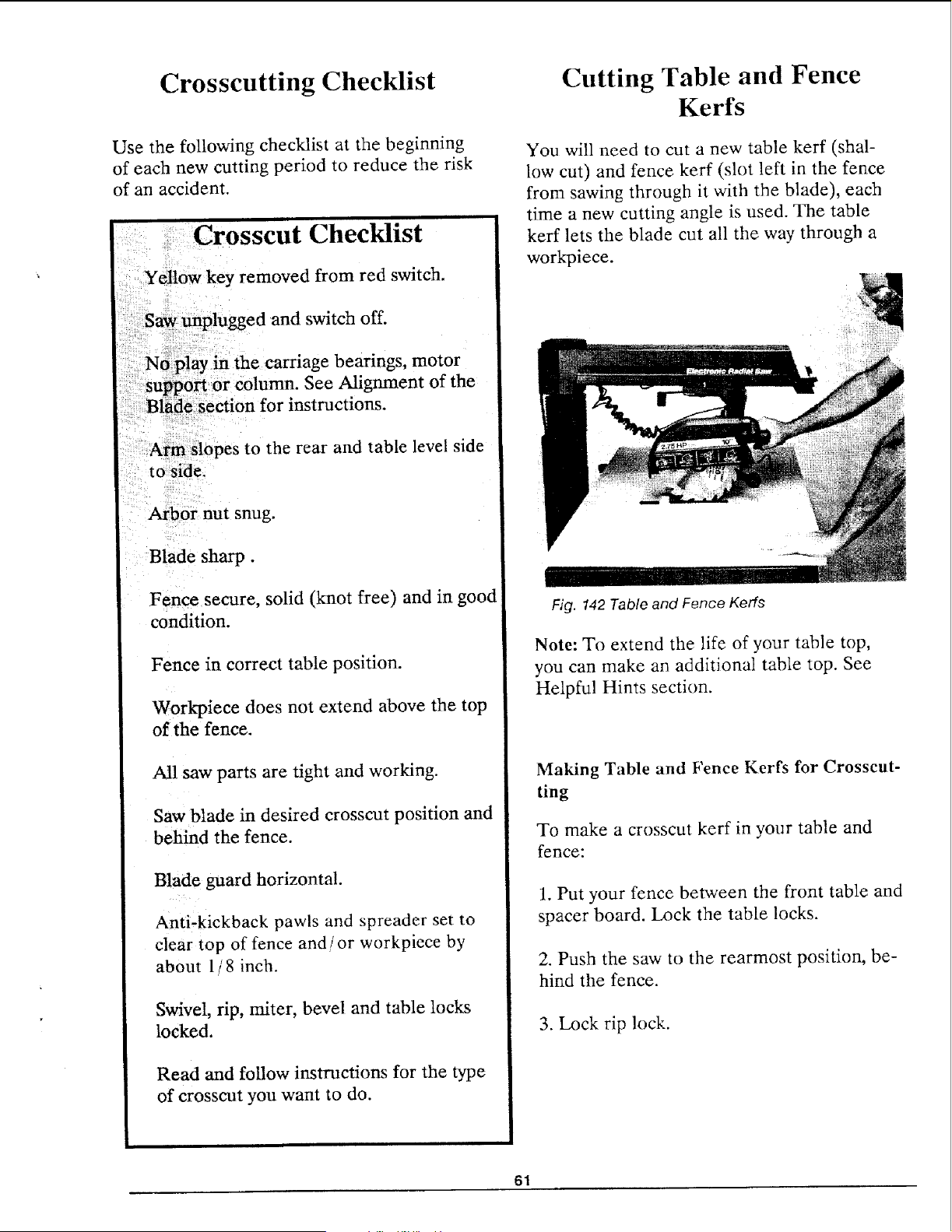
Crosscutting Checklist
Use the following checklist at the beginning
of each new cutting period to reduce the risk
of an accident.
Crosscut Checklist
Yellow key removed from red switch.
Saw unplugged and switch off.
N6 play in the carriage bearings, motor
suppori or column. See Alignment of the
Blacle section for instructions.
Arm slopes to the rear and table level side
to side.
Arbor nut snug.
Blade sharp.
Fence secure, solid (knot free) and in good
condition.
Fence in correct table position.
Workpiece does not extend above the top
of the fence.
All saw parts are tight and working.
Saw blade in desired crosscut position and
behind the fence.
Blade guard horizontal.
Anti-kickback pawls and spreader set to
clear top of fence and/or workpiece by
about 1/ 8 inch.
Swivel, rip, miter, bevel and table locks
locked.
Read and follow instructions for the type
of crosscut you want to do.
Cutting Table and Fence
Kerfs
You will need to cut a new table kerf (shal-
low cut) and fence kerr (slot left in the fence
from sawing through it with the blade), each
time a new cutting angle is used. The table
kerf lets the blade cut all the way through a
workpiece.
Fig. 142 Table and Fence Kerfs
Note: To extend the life of your table top,
you can make an additional table top. See
Helpful Hints section.
Making Table and Fence Kerfs for Crosscut-
ting
To make a crosscut kerf in your table and
fence:
1. Put your fence between the front table and
spacer board. Lock the table locks.
2. Push the saw to the rearmost position, be-
hind the fence.
3. Lock rip lock.
61
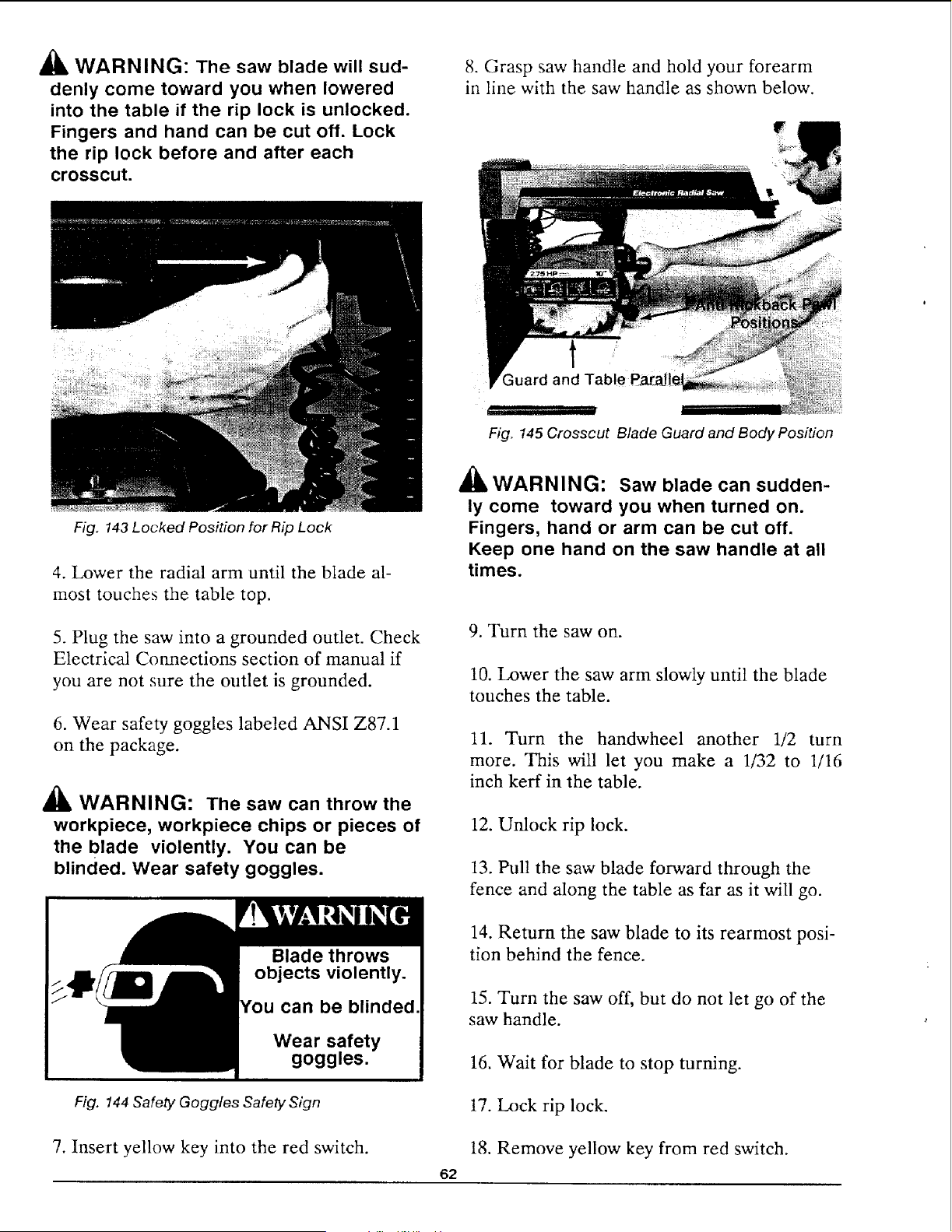
WARNING: The saw blade will sud-
denly come toward you when lowered
into the table if the rip lock is unlocked.
Fingers and hand can be cut off. Lock
the rip lock before and after each
crosscut.
Fig. 143 Locked Position for Rip Lock
4. Lower the radial arm until the blade al-
most touches the table top.
5. Plug the saw into a grounded outlet. Check
Electrical Connections section of manual if
you are not sure the outlet is grounded.
6. Wear safety goggles labeled ANSI Z87.1
on the package.
A
WARNING: The saw can throw the
workpiece, workpiece chips or pieces of
the blade violently. You can be
blinded. Wear safety goggles.
Wear safety
goggles.
Fig. 144 Safety Goggles Safety Sign
7. Insert yellow key into the red switch.
8. Grasp saw handle and hold your forearm
in line with the saw handle as shown below.
t
;uard and Table F
i i,n
I
Fig. 145 Crosscut Blade Guard and Body Position
£L _
ALWARNINL_: Saw blade can sudden-
ly come toward you when turned on.
Fingers, hand or arm can be cut off.
Keep one hand on the saw handle at all
times.
62
9. Turn the saw on.
10. Lower the saw arm slowly until the blade
touches the table.
11. Turn the handwheel another 1/2 turn
more. This will let you make a 1/32 to 1/16
inch kerr in the table.
12. Unlock rip lock.
13. Pull the saw blade forward through the
fence and along the table as far as it will go.
14. Return the saw blade to its rearmost posi-
tion behind the fence.
15. Turn the saw off, but do not let go of the
saw handle.
16. Wait for blade to stop turning.
17. Lock rip lock.
18. Remove yellow key from red switch.
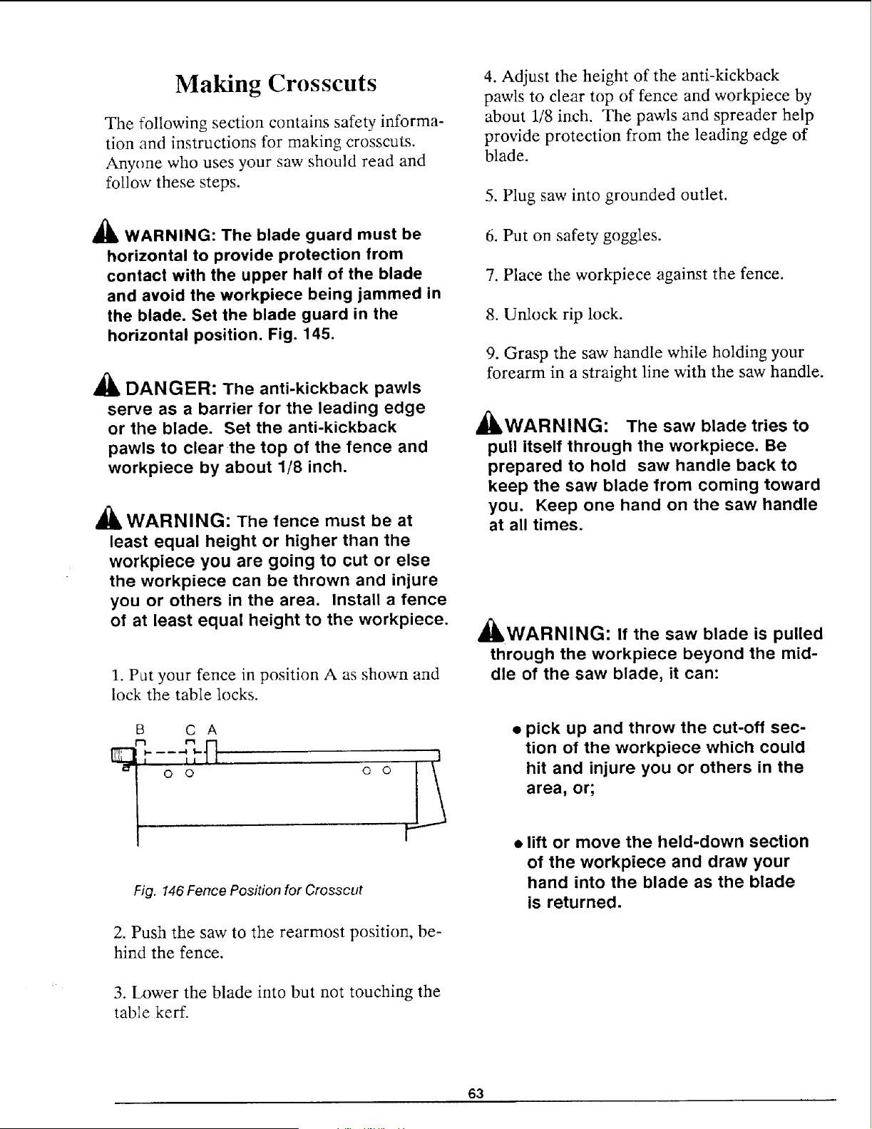
Making Crosscuts
The following section contains safety informa-
tion and instructions for making crosscuts.
Anyone who uses your saw should read and
follow these steps.
_ WARNING: The blade guard must be
horizontal to provide protection from
contact with the upper half of the blade
and avoid the workpiece being jammed in
the blade. Set the blade guard in the
horizontal position. Fig, 145.
DANGER: The anti-kickback pawls
serve as a barrier for the leading edge
or the blade. Set the anti-kickback
pawls to clear the top of the fence and
workpiece by about 1/8 inch.
WARNING: The fence must be at
least equal height or higher than the
workpiece you are going to cut or else
the workpiece can be thrown and injure
you or others in the area. Install a fence
of at least equal height to the workpiece.
1. Put your fence in position A as shown and
lock the table locks.
B C A
I I II II
_| 0 0 0 0
Fig. 146Fence Position for Crosscut
2. Push the saw to the rearmost position, be-
hind the fence.
3. I__)wer the blade into but not touching the
table kerf.
4. Adjust the height of the anti-kickback
pawls to clear top of fence and workpiece by
about 1/8 inch. The pawls and spreader help
provide protection from the leading edge of
blade.
5. Plug saw into grounded outlet.
6. Put on safety goggles.
7. Place the workpiece against the fence.
8. Unlock rip lock.
9. Grasp the saw handle while holding your
forearm in a straight line with the saw handle.
/k _
JkWARNING: The saw blade tries to
pull itself through the workpiece. Be
prepared to hold saw handle back to
keep the saw blade from coming toward
you. Keep one hand on the saw handle
at all times.
JkWARNING: If the saw blade is pulled
through the workpiece beyond the mid-
dle of the saw blade, it can:
• pick up and throw the cut-off sec-
tion of the workpiece which could
hit and injure you or others in the
area, or;
• lift or move the held-down section
of the workpiece and draw your
hand into the blade as the blade
is returned.
63
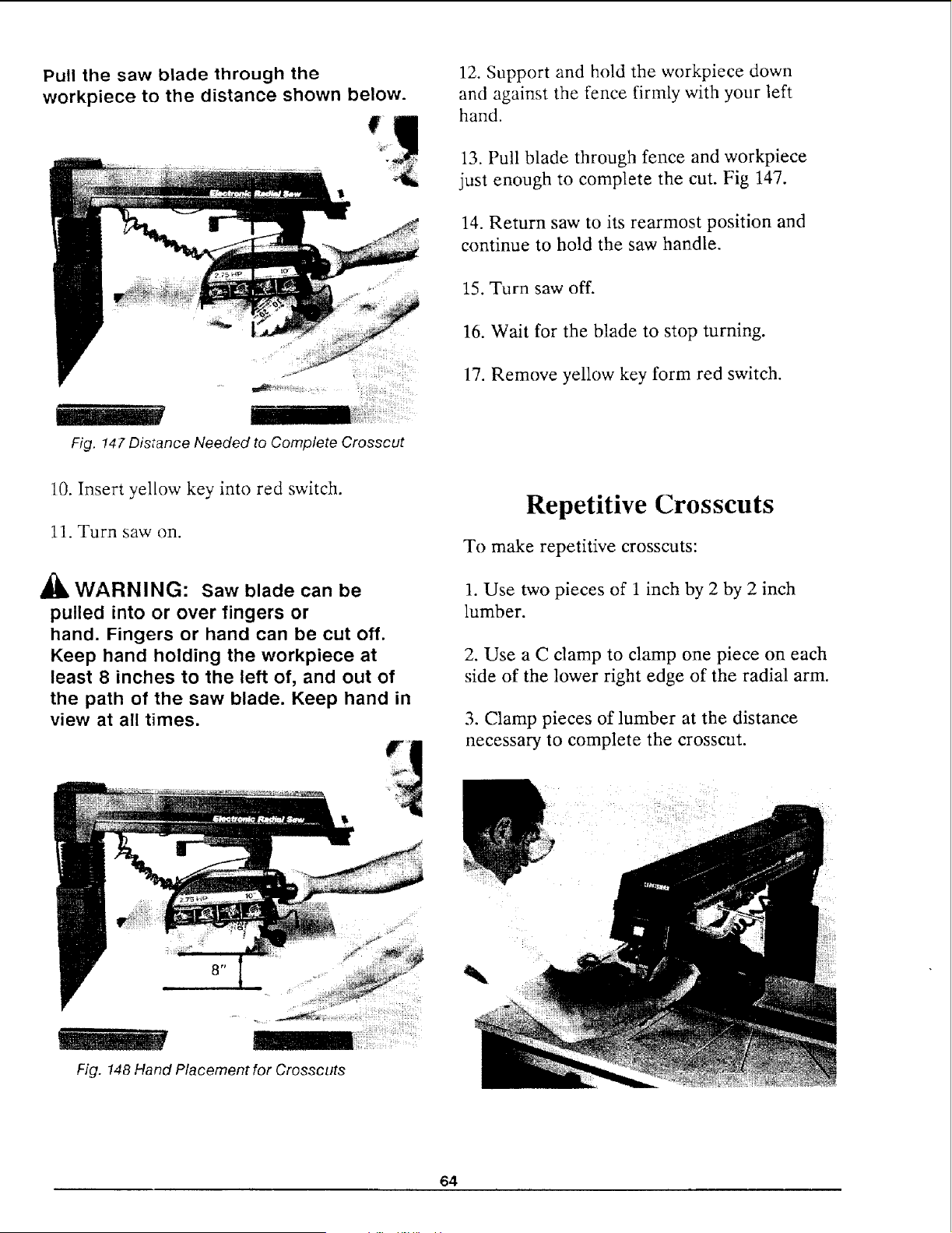
Pull the saw blade through the
workpiece to the distance shown below.
Fig. 147 Distance Needed to Complete Crosscut
12. Support and hold the workpiece down
and against the fence firmly with your left
hand.
13. Pull blade through fence and workpiece
just enough to complete the cut. Fig 147.
14. Return saw to its rearmost position and
continue to hold the saw handle.
15. Turn saw off.
16. Wait for the blade to stop turning.
17. Remove yellow key form red switch.
10. Insert yellow key into red switch.
11. Turn saw on.
l'k
AI_ WARNING: Saw blade can be
pulled into or over fingers or
hand. Fingers or hand can be cut off.
Keep hand holding the workpiece at
least 8 inches to the left of, and out of
the path of the saw blade. Keep hand in
view at all times.
Repetitive Crosscuts
To make repetitive crosscuts:
1. Use two pieces of 1 inch by 2 by 2 inch
lumber.
2. Use a C clamp to clamp one piece on each
side of the lower right edge of the radial arm.
3. Clamp pieces of lumber at the distance
necessary to complete the crosscut.
Fig. 148 Hand Placement for Crosscuts
64
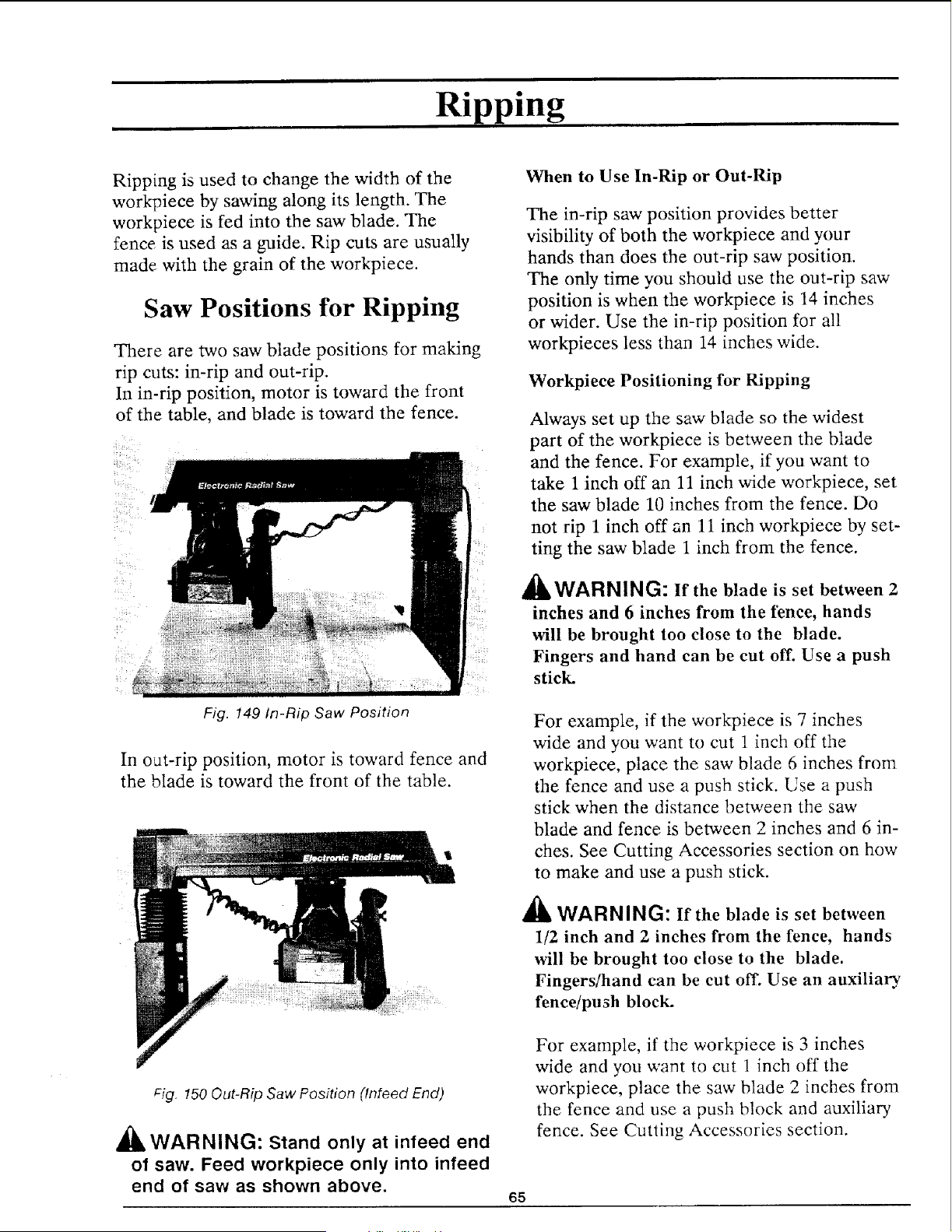
Ripping
Ripping is used to change the width of the
workpiece by sawing along its length. The
workpiece is fed into the saw blade. The
fence is used as a guide. Rip cuts are usually
made with the grain of the workpiece.
Saw Positions for Ripping
There are two saw blade positions for making
rip cuts: in-rip and out-rip.
In in-rip position, motor is toward the front
of the table, and blade is toward the fence.
Fig. 149 In-Rip Saw Position
In out-rip position, motor is toward fence and
the blade is toward the front of the table.
Pig. 150 Out-Rip Saw Position (lnteed End)
A__
JkWARNING: Stand only at infeed end
of saw. Feed workpiece only into infeed
end of saw as shown above.
When to Use In-Rip or Out-Rip
The in-rip saw position provides better
visibility of both the workpiece and your
hands than does the out-rip saw position.
The only time you should use the out-rip saw
position is when the workpiece is 14 inches
or wider. Use the in-rip position for all
workpieces less than 14 inches wide.
Workpiece Positioning for Ripping
Always set up the saw blade so the widest
part of the workpiece is between the blade
and the fence. For example, if you want to
take 1 inch off an 11 inch wide workpiece, set
the saw blade 10 inches from the fence. Do
not rip 1 inch off an 11 inch workpiece by set-
ting the saw blade 1 inch from the fence.
A --
AL WARNING: If the blade is set between 2
inches and 6 inches from the fence, hands
will be brought too close to the blade.
Fingers and hand can be cut off. Use a push
stick.
For example, if the workpiece is 7 inches
wide and you want to cut 1 inch off the
workpiece, place the saw blade 6 inches from
the fence and use a push stick. Use a push
stick when the distance between the saw
blade and fence is between 2 inches and 6 in-
ches. See Cutting Accessories section on how
to make and use a push stick.
_k WARNING: If the blade is set between
1/2 inch and 2 inches from the fence, hands
will be brought too close to the blade.
Fingers/hand can be cut off. Use an auxiliary
fence/push block.
For example, if the workpiece is 3 inches
wide and you want to cut 1 inch off the
workpiece, place the saw blade 2 inches from
the fence and use a push block and auxiliary
fence. See Cutting Accessories section.
65
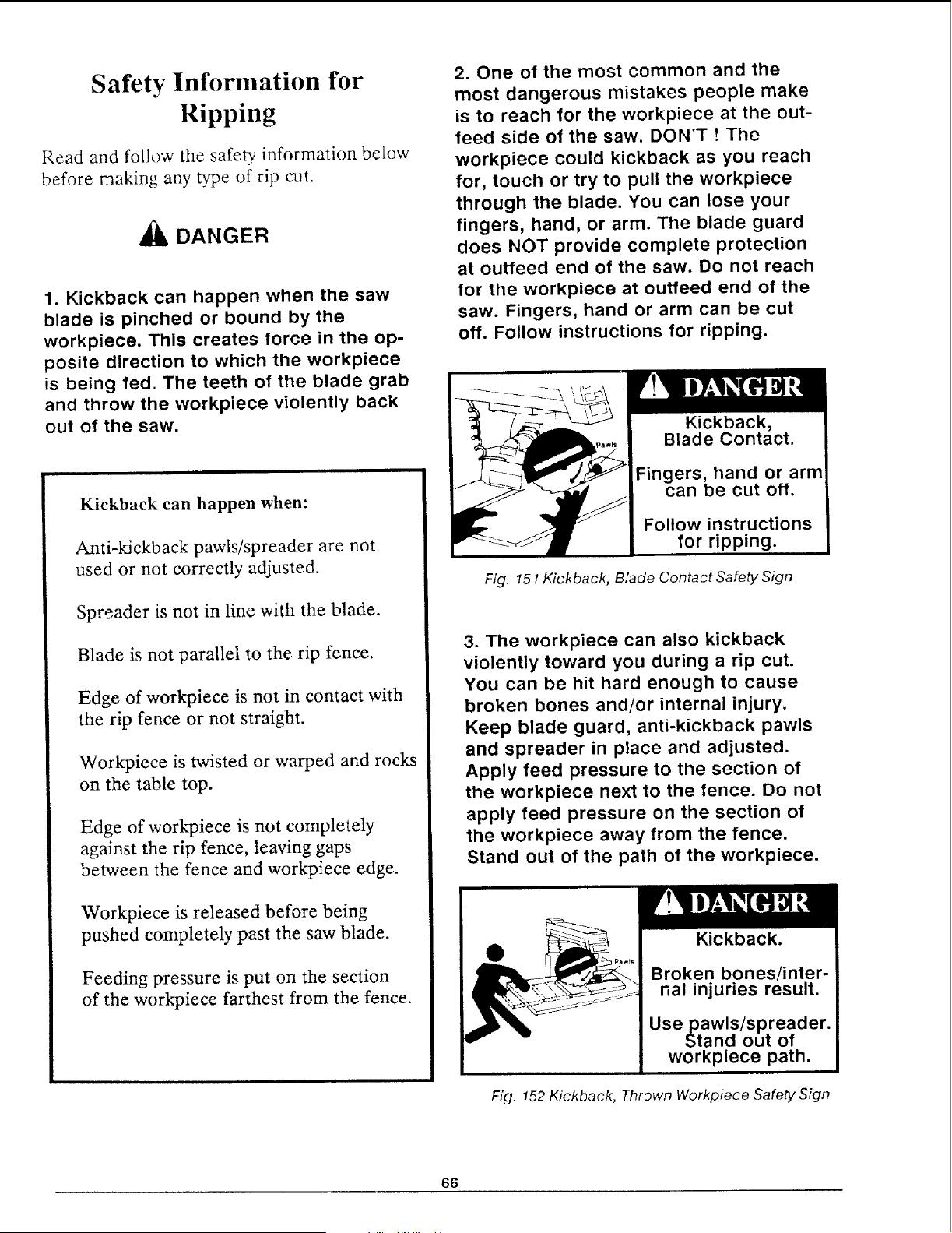
Safety Information for
Ripping
Read and follow the safeb information below
before making any type of rip cut.
_lb DANGER
1. Kickback can happen when the saw
blade is pinched or bound by the
workpiece. This creates force in the op-
posite direction to which the workpiece
is being fed. The teeth of the blade grab
and throw the workpiece violently back
out of the saw.
Kickback can happen when:
Anti-kickback pawls/spreader are not
used or not correctly adjusted.
Spreader is not in line with the blade.
Blade is not parallel to the rip fence,
Edge of workpiece is not in contact with
the rip fence or not straight.
Workpiece is twisted or warped and rocks
on the table top.
Edge of workpiece is not completely
against the rip fence, leaving gaps
between the fence and workpiece edge.
Workpiece is released before being
pushed completely past the saw blade.
Feeding pressure is put on the section
of the workpiece farthest from the fence.
2. One of the most common and the
most dangerous mistakes people make
is to reach for the workpiece at the out-
feed side of the saw. DON'T t The
workpiece could kickback as you reach
for, touch or try to pull the workpiece
through the blade. You can lose your
fingers, hand, or arm. The blade guard
does NOT provide complete protection
at outfeed end of the saw. Do not reach
for the workpiece at outfeed end of the
saw. Fingers, hand or arm can be cut
off. Follow instructions for ripping.
Kickback,
Blade Contact.
Fingers, hand or arm
can be cut off.
Follow instructions
for ripping.
Fig. 15t Kickback, Blade Contact Safety Sign
3. The workpiece can also kickback
violently toward you during a rip cut.
You can be hit hard enough to cause
broken bones and/or internal injury.
Keep blade guard, anti-kickback pawls
and spreader in place and adjusted.
Apply feed pressure to the section of
the workpiece next to the fence. Do not
apply feed pressure on the section of
the workpiece away from the fence.
Stand out of the path of the workpiece.
Fig. 152 Kickback, Thrown Workpiece Safety Sign
66
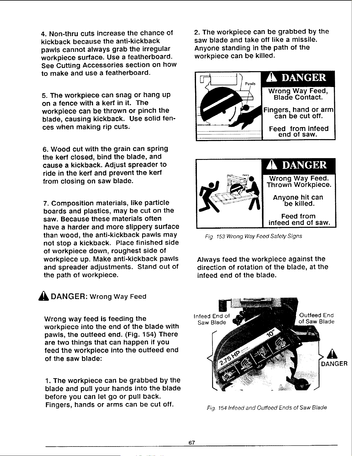
4. Non-thru cuts increase the chance of
kickback because the anti-kickback
pawls cannot always grab the irregular
workpiece surface. Use a featherboard.
See Cutting Accessories section on how
to make and use a featherboard.
5. The workpiece can snag or hang up
on a fence with a kerf in it. The
workpiece can be thrown or pinch the
blade, causing kickback. Use solid fen-
ces when making rip cuts.
2. The workpiece can be grabbed by the
saw blade and take off like a missile.
Anyone standing in the path of the
workpiece can be killed.
of saw.
6. Wood cut with the grain can spring
the kerr closed, bind the blade, and
cause a kickback. Adjust spreader to
ride in the kerr and prevent the kerf
from closing on saw blade.
7. Composition materials, like particle
boards and plastics, may be cut on the
saw. Because these materials often
have a harder and more slippery surface
than wood, the anti-kickback pawls may
not stop a kickback. Place finished side
of workpiece down, roughest side of
workpiece up. Make anti-kickback pawls
and spreader adjustments. Stand out of
the path of workpiece.
Fig 153 Wrong Way Feed Safety Signs
Always feed the workpiece against the
direction of rotation of the blade, at the
infeed end of the blade.
_lb DANGER: Wrong way Feed
Wrong way feed is feeding the
workpiece into the end of the blade with
pawls, the outfeed end. (Fig. 154) There
are two things that can happen if you
feed the workpiece into the outfeed end
of the saw blade:
Infeed End of
Saw Blade
Outfeed End
of Saw Blade
A
DANGER
1. The workpiece can be grabbed by the
blade and pull your hands into the blade
before you can let go or pull back.
Fingers, hands or arms can be cut off.
Fig. 154 Infeed and Outfeed Ends of Saw Blade
67
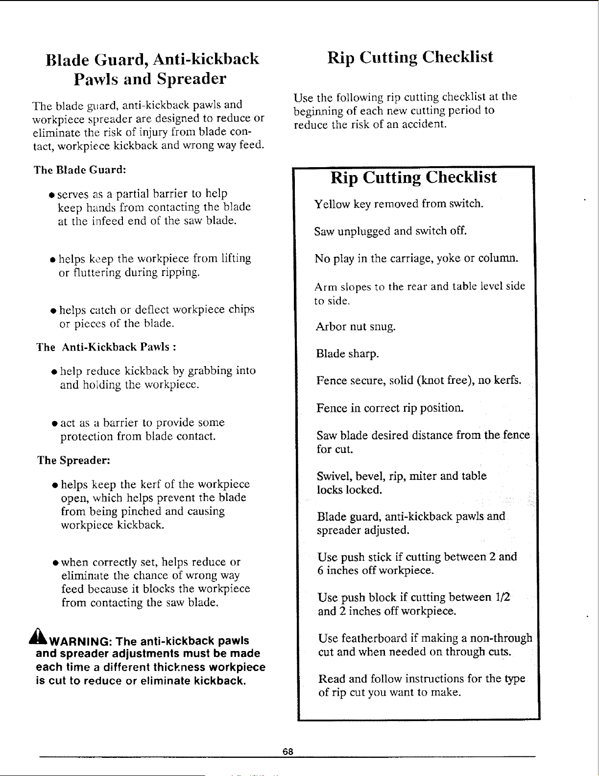
Blade Guard, Anti-kickback
Pawls and Spreader
The blade guard, anti-kickback pawls and
workpiece spreader are designed to reduce or
eliminate the risk of injury from blade con-
tact, workpiece kickback and wrong way feed.
The Blade Guard:
• serves as a partial barrier to help
keep hands from contacting the blade
at the infeed end of the saw blade.
• helps keep the workpiece from lifting
or fluttering during ripping.
• helps catch or deflect workpiece chips
or pieces of the blade.
The Anti-Kickback Pawls :
• help reduce kickback by grabbing into
and holding the workpiece.
• act as a barrier to provide some
protection from blade contact.
The Spreader:
• helps keep the kerr of the workpiece
open, which helps prevent the blade
from being pinched and causing
workpiece kickback.
when correctly set, helps reduce or
eliminate the chance of wrong way
feed because it blocks the workpiece
from contacting the saw blade.
_I_WARNING: The anti-kickback pawls
and spreader adjustments must be made
each time a different thickness workpiece
is cut to reduce or eliminate kickback,
Rip Cutting Checklist
Use the following rip cutting checklist at the
beginning of each new cutting period to
reduce the risk of an accident.
Rip Cutting Checklist
Yellow key removed from switch.
Saw unplugged and switch off.
No play in the carriage, yoke or column.
Arm slopes to the rear and table level side
to side.
Arbor nut snug.
Blade sharp.
Fence secure, solid (knot free), no kerfs.
Fence in correct rip position.
Saw blade desired distance from the fence
for cut.
Swivel, bevel, rip, miter and table
locks locked.
Blade guard, anti-kickback pawls and
spreader adjusted.
Use push stick if cutting between 2 and
6 inches off workpiece.
Use push block if cutting between 1/2
and 2 inches off workpiece.
Use featherboard if making a non-through
cut and when needed on through cuts.
Read and follow instructions for the type
of rip cut you want to make.
68
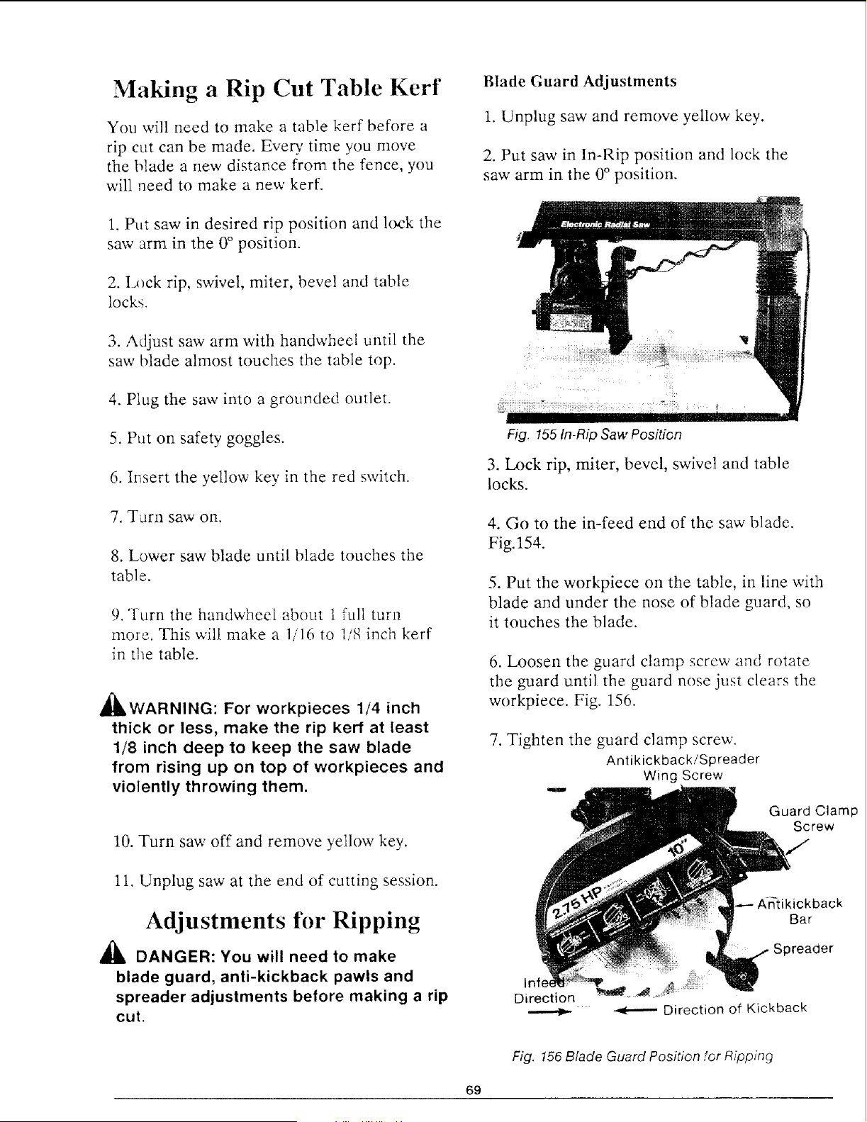
Making a Rip Cut Table Kerf
You will need to make a table kerf before a
rip cut can be made. Eve n ' time you move
the blade a new distance from the fence, you
will need to make a new kerf.
1. Put saw in desired rip position and lock the
saw arm in the 0° position.
2. Lock rip, swivel, miter, bevel and table
locks.
3. Adjust saw arm with handwheel until the
saw blade almost touches the table top.
4. Plug the saw into a grounded outlet.
5. Put on safety goggles.
6. IT_sert the yellow key in the red switch.
7. Turn saw on.
8. Lower saw blade until blade touches the
table.
9. "[urn the handwheel about 1 full turn
more. This will make a 1/16 to 1/8 inch kerf
in the table.
_IbWARNING: For workpieces 1/4 inch
thick or less, make the rip kerr at least
1/8 inch deep to keep the saw blade
from rising up on top of workpieces and
violently throwing them.
10. Turn saw off and remove yellow key.
11. Unplug saw at the end of cutting session.
Adjustments for Ripping
_i, DANGER: You will need to make
blade guard, anti-kickback pawls and
spreader adjustments before making a rip
cut.
Blade Guard Adjustments
1. Unplug saw and remove yellow key.
2. Put saw in In-Rip position and lock the
saw arm in the 0 ° position.
Fig. 155 In-Rip Saw Position
3. Lock rip, miter, bevel, swivel and table
locks.
4. Go to the in-feed end of the saw blade.
Fig. 154.
5. Put the workpiece on the table, in line with
blade and under the nose of blade guard, so
it touches the blade.
6. Loosen the guard clamp screw and rotate
the guard until the guard nose just clears the
workpiece. Fig. 156.
7. Tighten the guard clamp screw.
Antikickback/Spreader
Wing Screw
Guard Clamp
Screw
Direction
kback
Bar
Spreader
Direction of Kickback
Fig. 156 Blade Guard Position for Ripping
69
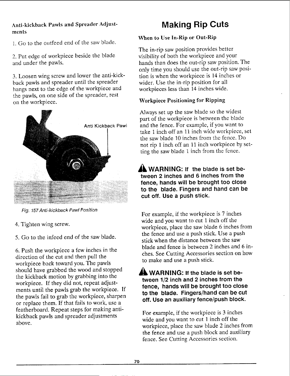
Anti-kickback Pawls and Spreader Adjust- Making Rip Cuts
ments
!. Go to the outfeed end of the saw blade.
2. Put edge of workpiece beside the blade
and under the pawls.
3. Loosen wing screw and lower the anti-kick-
back pawls and spreader until the spreader
hangs next to the edge of the workpiece and
the pawls, on one side of the spreader, rest
on the workpiece.
Anti Kickback Pawt
Fig. 157Anti-kickback Pawl Position
4. Tighten wing screw.
5. Go to the in_feed end of the saw blade.
6. Push the workpiece a few inches in the
direction of the cut and then pull the
workpiece back toward you. The pawls
should have grabbed the wood and stopped
the kickback motion by grabbing into the
workpiece. If they did not, repeat adjust-
ments until the pawls grab the workpiece. If
the pawls fail to grab the workpiece, sharpen
or replace them. If that fails to work, use a
featherboard. Repeat steps for making anti-
kickback pawls and spreader adjustments
above.
When to Use In-Rip or Out-Rip
The in-rip saw position provides better
visibility of both the workpiece and your
hands than does the out-rip saw position. The
only time you should use the out-rip saw posi-
tion is when the workpiece is 14 inches or
wider. Use the in-rip position for all
workpieces less than 14 inches wide.
Workpiece Positioning for Ripping
Always set up the saw blade so the widest
part of the workpiece is between the blade
and the fence. For example, if you want to
take 1 inch off an 11 inch wide workpiece, set
the saw blade 10 inches from the fence. Do
not rip 1 inch off an 11 inch workpiece by set-
ting the saw blade 1 inch from the fence.
A WARNING: If the blade is set be-
tween 2 inches and 6 inches from the
fence, hands will be brought too close
to the blade. Fingers and hand can be
cut off. Use a push stick.
For example, if the workpiece is 7 inches
wide and you want to cut 1 inch off the
workpiece, place the saw blade 6 inches from
the fence and use a push stick. Use a push
stick when the distance between the saw
blade and fence is between 2 inches and 6 in-
ches. See Cutting Accessories section on how
to make and use a push stick.
WARNING: If the blade is set be-
tween 1/2 inch and 2 inches from the
fence, hands will be brought too close
to the blade. Fingers/hand can be cut
off. Use an auxiliary fence/push block.
For example, if the workpiece is 3 inches
wide and you want to cut 1 inch off the
workpiece, place the saw blade 2 inches from
the fence and use a push block and auxiliary
fence. See Cutting Accessories section.
7O
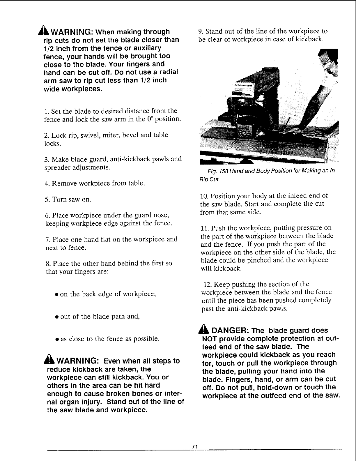
_IL WARNING: When making through
rip cuts do not set the blade closer than
1/2 inch from the fence or auxiliary
fence, your hands will be brought too
close to the blade. Your fingers and
hand can be cut off. Do not use a radial
arm saw to rip cut less than 1/2 inch
wide workpieces.
1. Set the blade to desired distance from the
fence and lock the saw arm in the 0° position.
2. I_x)ck rip, swivel, miter, bevel and table
locks.
3. Make blade guard, anti-kickback pawls and
spreader adjustments.
4. Remove workpiece from table.
5. Turn saw on.
6. Place work_iece under the guard nose,
keeping workpiece edge against the fence.
7. Place one hand flat on the workpiece and
next to fence.
8. Place the other hand behind the first so
that your fingers are:
• on the back edge of workpiece;
• out of the blade path and,
• as close to the fence as possible.
llLWARNIN(3: Even when all steps to
reduce kickback are taken, the
workpiece can still kickback. You or
others in the area can be hit hard
enough to cause broken bones or inter-
nal organ injury. Stand out of the line of
the saw blade and workpiece.
9. Stand out of the line of the workpiece to
be clear of workpiece in case of kickback.
Fig. 158 Hand and Body Position for Making an In-
Rip Cut
10. Position your body at the infeed end of
the saw blade. Start and complete the cut
from that same side.
11. Push the workpiece, putting pressure on
the part of the workpiece between the blade
and the fence. If you push the part of the
workpiece on the other side of the blade, the
blade could be pinched and the workpiece
will kickback.
12. Keep pushing the section of the
workpiece between the blade and the fence
until the piece has been pushed completely
past the anti-kickback pawls.
• i_ DANGER: The blade guard does
NOT provide complete protection at out-
feed end of the saw blade. The
workpiece could kickback as you reach
for, touch or pull the workpiece through
the blade, pulling your hand into the
blade. Fingers, hand, or arm can be cut
off. Do not pull, hold-down or touch the
workpiece at the outfeed end of the saw.
71
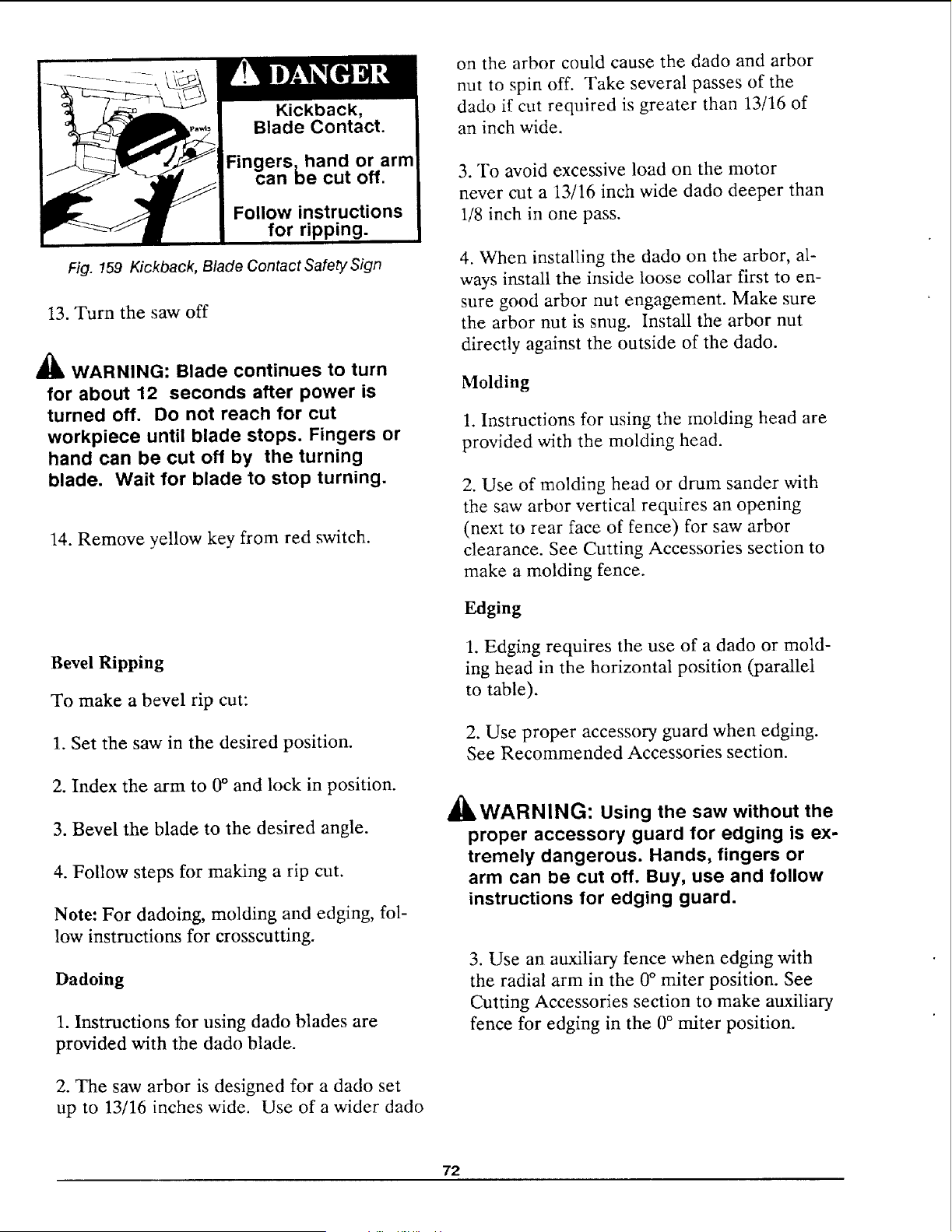
Kickback,
Blade Contact.
Fingers,hand or arm
can be cut off.
Follow instructions
for ripping.
Fig. !59 Kickback, Blade Contact Safety Sign
13. Turn the saw off
_ WARNING: Blade continues to turn
for about 12 seconds after power is
turned off. Do not reach for cut
workpiece until blade stops. Fingers or
hand can be cut off by the turning
blade. Wait for blade to stop turning.
14. Remove yellow key from red switch.
Bevel Ripping
To make a bevel rip cut:
1. Set the saw in the desired position.
2. Index the arm to 0° and lock in position.
3. Bevel the blade to the desired angle.
4. Follow steps for making a rip cut.
Note: For dadoing, molding and edging, fol-
low instructions for crosscutting.
Dadoing
1. Instructions for using dado blades are
provided with the dado blade.
2. The saw arbor is designed for a dado set
up to 13/16 inches wide. Use of a wider dado
on the arbor could cause the dado and arbor
nut to spin off. Take several passes of the
dado if cut required is greater than 13/16 of
an inch wide.
3. To avoid excessive load on the motor
never cut a 13/16 inch wide dado deeper than
1/8 inch in one pass.
4. When installing the dado on the arbor, al-
ways install the inside loose collar first to en-
sure good arbor nut engagement. Make sure
the arbor nut is snug. Install the arbor nut
directly against the outside of the dado.
Molding
!. Instructions for using the molding head are
provided with the molding head.
2. Use of molding head or drum sander with
the saw arbor vertical requires an opening
(next to rear face of fence) for saw arbor
clearance. See Cutting Accessories section to
make a molding fence.
Edging
1. Edging requires the use of a dado or mold-
ing head in the horizontal position (parallel
to table).
2. Use proper accessory guard when edging.
See Recommended Accessories section.
_'k A
_LWARNINL_: Using the saw without the
proper accessory guard for edging is ex-
tremely dangerous. Hands, fingers or
arm can be cut off. Buy, use and follow
instructions for edging guard.
3. Use an auxiliary fence when edging with
the radial arm in the 0° miter position. See
Cutting Accessories section to make auxiliary
fence for edging in the 0 ° miter position.
72
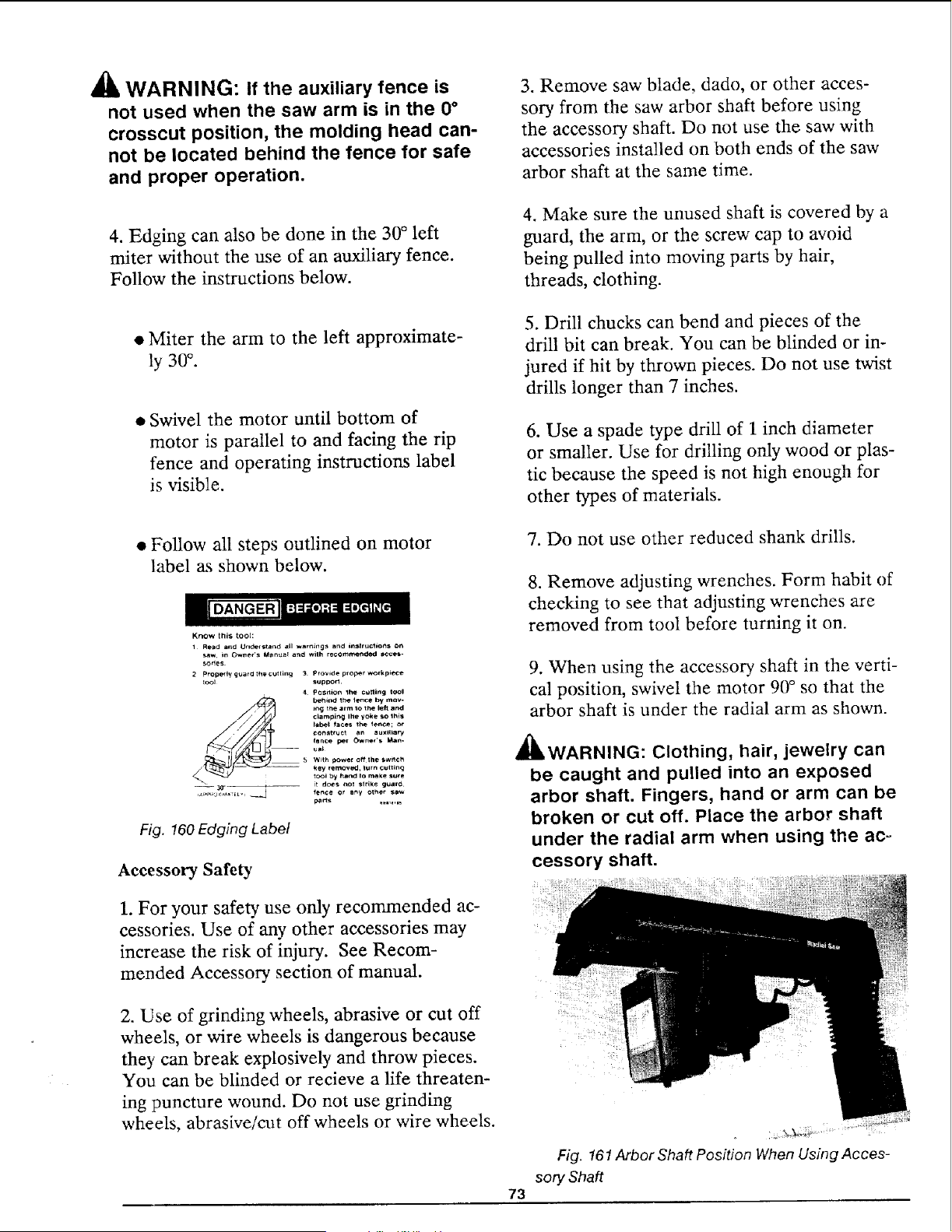
_lb WARNING: If the auxiliary fence is
not used when the saw arm is in the 0°
crosscut position, the molding head can-
not be located behind the fence for safe
and proper operation.
3. Remove saw blade, dado, or other acces-
sory from the saw arbor shaft before using
the accessory shaft. Do not use the saw with
accessories installed on both ends of the saw
arbor shaft at the same time.
4. Edging can also be done in the 30 ° left
miter without the use of an auxiliary fence.
Follow the instructions below.
4. Make sure the unused shaft is covered by a
guard, the arm, or the screw cap to avoid
being pulled into moving parts by hair,
threads, clothing.
• Miter the arm to the left approximate-
ly 30 °.
• Swivel the motor until bottom of
motor is parallel to and facing the rip
fence and operating instructions label
is visible.
5. Drill chucks can bend and pieces of the
drill bit can break. You can be blinded or in-
jured if hit by thrown pieces. Do not use twist
drills longer than 7 inches.
6. Use a spade type drill of 1 inch diameter
or smaller. Use for drilling only wood or plas-
tic because the speed is not high enough for
other types of materials.
• Follow all steps outlined on motor
label as shown below.
Know this tool:
1 Read and Understand all wnrnings and i_trg_lons on
_w, in Owner's M_nusE and Wilh recommended acces-
sodes.
2 Properly guard _hecu_fir_ 3 Provide proper wotkp_Ce
_1 supporl.
4 Pos_on itte cgtting tool
___ behind 1he lence by mov-
ing the arm to the left and
c{amping Ihe yoke so this
[abet tac_ the _eoce;
consttuc_ an auxiliary
fence per O_ne_'s Man.
- ua_
5 W_th power off the swl_ch
tool by hand Io m_ke suce
_ it dc_s not strike guar_
__=i fence or any other sawI_P_ £1_& [ L v
Fig. 160 Edging Label
Accessory Safety
7. Do not use other reduced shank drills.
8. Remove adjusting wrenches. Form habit of
checking to see that adjusting wrenches are
removed from tool before turning it on.
9. When using the accessory shaft in the verti-
cal position, swivel the motor 90 ° so that the
arbor shaft is under the radial arm as shown.
_WARNING: Clothing, hair, jewelry can
be caught and pulled into an exposed
arbor shaft. Fingers, hand or arm can be
broken or cut off. Place the arbor shaft
under the radial arm when using the aco
cessory shaft.
1. For your safety use only recommended ac-
cessories. Use of any other accessories may
increase the risk of injury. See Recom-
mended Accessory section of manual.
2. Use of grinding wheels, abrasive or cut off
wheels, or wire wheels is dangerous because
they can break explosively and throw pieces.
You can be blinded or recieve a life threaten-
ing puncture wound. Do not use grinding
wheels, abrasive/cut off wheels or wire wheels.
73
Fig. 161Arbor Shaft Position When Using Acces-
sory Shaft
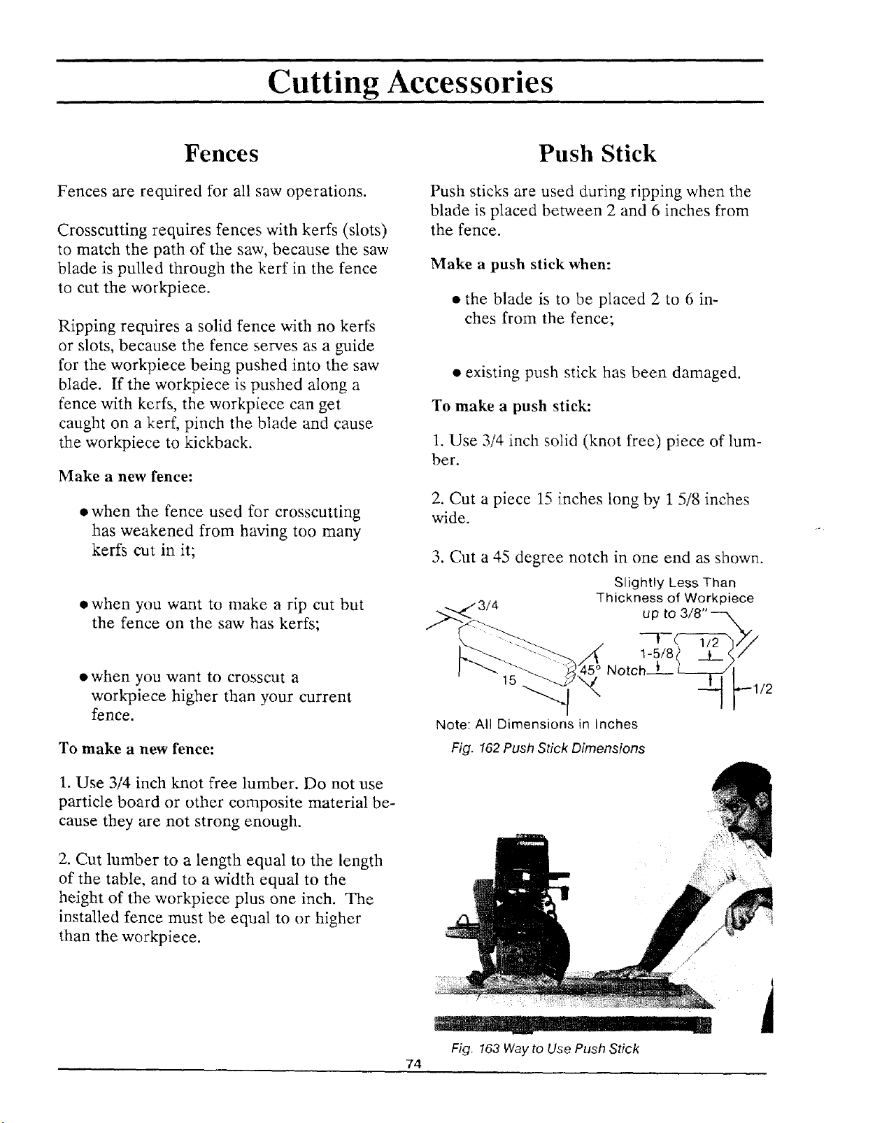
Cutting Accessories
Fences
Fences are required for all saw operations.
Crosscutting requires fences with kerfs (slots)
to match the path of the saw, because the saw
blade is pulled through the kerf in the fence
to cut the workpiece.
Ripping requires a solid fence with no kerfs
or slots, because the fence serves as a guide
for the workpiece being pushed into the saw
blade. If the workpiece is pushed along a
fence with kerfs, the workpiece can get
caught on a kerf, pinch the blade and cause
the workpiece to kickback.
Make a new fence:
• when the fence used for crosscutting
has weakened from having too many
kerfs cut in it;
• when you want to make a rip cut but
the fence on the saw has kerfs;
• when you want to crosscut a
workpiece higher than your current
fence.
To make a new fence:
1. Use 3/4 inch knot free lumber. Do not use
particle board or other composite material be-
cause they are not strong enough.
2. Cut lumber to a length equal to the length
of the table, and to a width equal to the
height of the workpiece plus one inch. The
installed fence must be equal to or higher
than the workpiece.
74
Push Stick
Push sticks are used during ripping when the
blade is placed between 2 and 6 inches from
the fence.
Make a push stick when:
• the blade is to be placed 2 to 6 in-
ches from the fence;
• existing push stick has been damaged.
To make a push stick:
1. Use 3/4 inch solid (knot free) piece of lum-
ber.
2. Cut a piece 15 inches long by 1 5/8 inches
wide.
3. Cut a 45 degree notch in one end as shown.
Slightly Less Than
Thickness of Workpiece
u p to 318" --_
1-5/8i
Note: All Dimensions in Inches
Fig. 162 Push Stick Dimensions
Fig. 163 Way to Use Push Stick
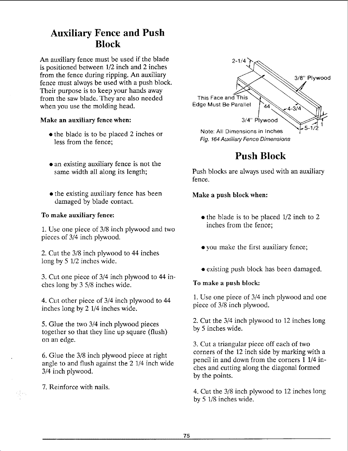
• f,•
Auxiliary Fence and Push
Block
An auxiliary fence must be used if the blade
is positioned between 1/2 inch and 2 inches
from the fence during ripping. An auxiliary
fence must always be used with a push block.
Their purpose is to keep your hands away
from the saw blade. They are also needed
when you use the molding head.
Make an auxiliary fence when:
• the blade is to be placed 2 inches or
less from the fence;
• an existing at_dliary fence is not the
same width all along its length;
• the existing auxiliary fence has been
damaged by blade contact.
To make auxiliary fence:
1. Use one piece of 3/8 inch plywood and two
pieces of 3/4 inch pb_ood.
2. Cut the 3/8 inch plywood to 44 inches
long by 5 1/2 inches wide.
3. Cut one piece of 3/4 inch plywood to 44 in-
ches long by 3 5/8 inches wide.
4. Cut other piece of 3/4 inch plywood to 44
inches long by 2 1/4 inches wide.
5. Glue the two 3/4 inch plywood pieces
together so that they line up square (flush)
on an edge.
6. Glue the 3/8 inch plywood piece at right
angle to and flush against the 2 1/4 inch wide
3/4 inch plywood.
7. Reinforce with nails.
3/8" Plywood
This Face and This
Edge Must Be Parallel
3/4" Plywood
Note: All Dimensions in Inches
Fig. 164Auxiliary Fence Dimensions
Push Block
Push blocks are always used with an auxiliary
fence.
Make a push block when:
• the blade is to be placed 1/2 inch to 2
inches from the fence;
• you make the first auxiliary fence;
• existing push block has been damaged.
To make a push block:
1. Use one piece of 3/4 inch plywood and one
piece of 3/8 inch plywood.
2. Cut the 3/4 inch plywood to 12 inches long
by 5 inches wide.
3. Cut a triangular piece off each of two
corners of the 12 inch side by marking with a
pencil in and down from the corners 1 1/4 in-
ches and cutting along the diagonal formed
by the points.
4. Cut the 3/8 inch plywood to 12 inches long
by 5 1/8 inches wide.
75
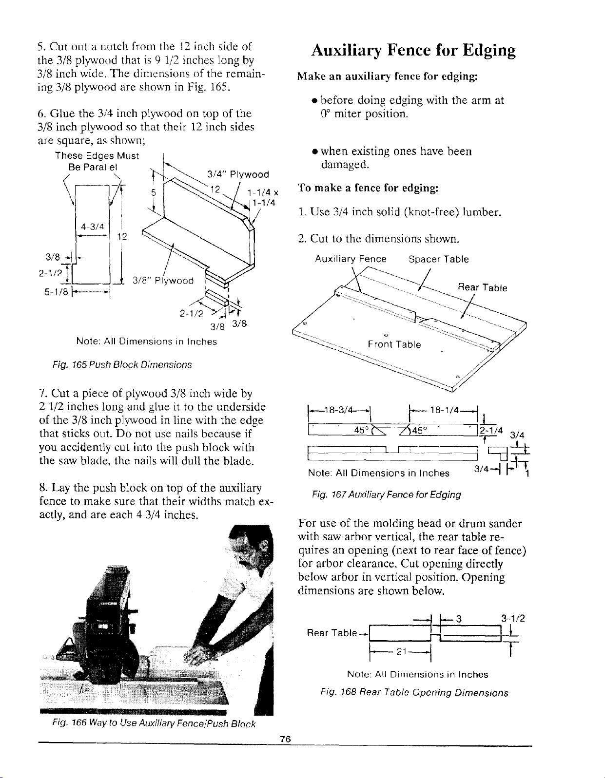
5. Cut out a notch from the 12 inch side of
the 3/8 plywood that is 9 1/2 inches long by
3/8 inch wide. The dimensions of the remain-
ing 3/8 plywood are shown in Fig. 165.
6. Glue the 3/4 inch plywood on top of the
3/8 inch plywood so that their 12 inch sides
are square, as shown;
3/8
2-1/2![
These Edges Must
Be Parallel
\
1
s-1/8F---4
3/4" Plywood
1-1/4 x
1-1/4
3/8" Plywood
/<
2-1/2
3/8 3/&
Note: All Dimensions in Inches
Fig. 165 Push Block Dimensions
Auxiliary Fence for Edging
Make an auxiliary fence for edging:
* before doing edging with the arm at
0° miter position.
• when existing ones have been
damaged.
To make a fence for edging:
1. Use 3/4 inch solid (knot-free) lumber.
2. Cut to the dimensions shown.
Auxiliary Fence Spacer Table
Rear Table
7. Cut a piece of plywood 3/8 inch wide by
2 1/2 inches long and glue it to the underside
of the 3/8 inch plywood in line with the edge
that sticks out. Do not use nails because if
you accjOently cut into the push block with
the saw blade, the nails will dull the blade.
8. Lay the push block on top of the auxiliary
fence to make sure that their widths match ex-
actly, and are each 4 3/4 inches.
_-,_ , 'r _ ' ' ] !PI __
Fig. 166 Way to Use Auxiliary Fence/Push Block
_---18-3/4-_ p 1811/4---_j
1" " 45°_74/45° " " 12"1/4 314
T- .1_
.o.e:A,,O. oosions,:,nohe
Fig. 167Auxiliary Fence for Edging
For use of the molding head or drum sander
_qth saw arbor vertical, the rear table re-
quires an opening (next to rear face of fence)
for arbor clearance. Cut opening directly
below arbor in vertical position. Opening
dimensions are shown below.
Rear Table-,- I ---1 t_- 3 l!3-1/2
I
_- 2t ----_ [
Note: All Dimensions in Inches
Fig. 168 Rear Table Opening Dimensions
76
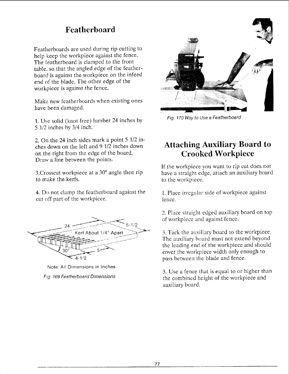
Featherboard
Featherboards are used during rip cutting to
help keep the workpiece against the fence.
The featherboard is clamped to the front
table, so that the angled edge of the feather-
board is against the workpiece on the infeed
end of the blade. The other edge of the
workpiece is against the fence.
Make new featherboards when existing ones
have been damaged.
1. Use solid (knot free) lumber 24 inches by
5 1/2 inches by 3/4 inch.
2. On the 24 inch sides mark a point 5 1/2 in-
ches down on the left and 9 1/2 inches down
on the right from the edge of the board.
Draw a line between the points.
3.Crosscut workpiece at a 30 ° angle then rip
to make the kerfs.
4. Do not clamp the featherboard against the
cut off part of the workpiece.
Note: All Dimensions in Inches
F;ff. 169 Featherboard Dimensions
Attaching Auxiliary Board to
Crooked Workpiece
If the workpiece you want to rip cut does not
have a straight edge, attach an auxiliary board
to the workpiece.
1. Place irregular side of workpiece against
fence.
2. Place straight edged auxilia U board on top
of workpiece and against fence.
3. Tack the auxilia U board to the workpiece.
The atLxiliary board must not extend beyond
the leading end of the workpiece and should
cover the workpiece width only enough to
pass between the blade and fence.
3. Use a fence that is equal to or higher than
the combined height of the workpiece and
auxiliary board.
77
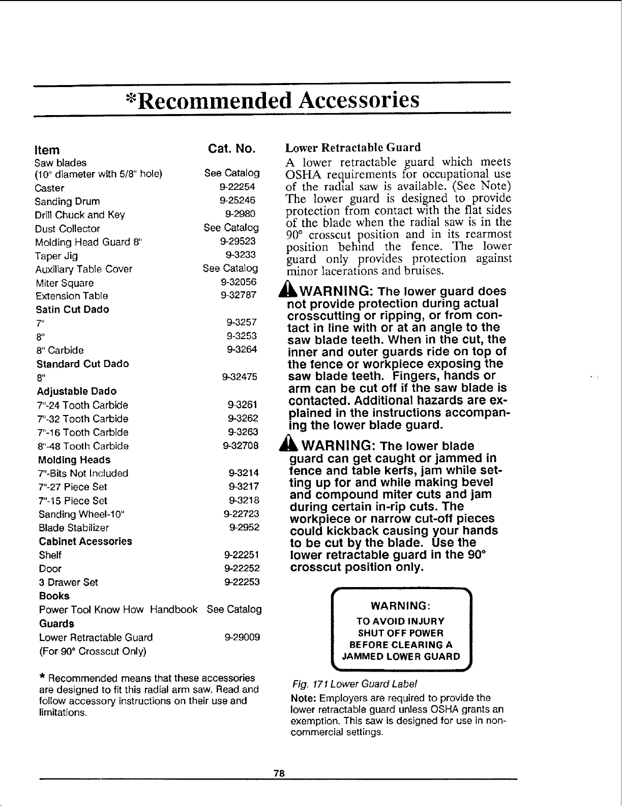
*Recommended Accessories
Item Cat. No.
Saw blades
(10" diameter with 5/8" hole) See Catalog
Caster 9-22254
Sanding Drum 9-25246
Drill Chuck and Key 9-2980
Dust Collector See Catalog
Molding Head Guard 8" 9-29523
Taper Jig 9-3233
Auxiliary Table Cover See Catalog
Miter Square 9-32056
Extension Table 9-32787
Satin Cut Dado
7" 9-3257
8" 9-3253
8" Carbide 9-3264
Standard Cut Dado
8" 9-32475
Adjustable Dado
7"-24 Tooth Carbide 943261
7"-32 Tooth Carbide 9-3262
7"-16 Tooth Carbide 9-3263
8"-48 Tooth Carbide 9-32708
Molding Heads
7"-Bits Not Included 9-3214
7"-27 Piece Set 9-3217
7"-15 Piece Set 9-3218
Sanding Wheel-10" 9-22723
Blade Stabilizer 9-2952
Cabinet Acessories
Shelf 9-22251
Door 9-22252
3 Drawer Set 9-22253
Books
Power Tool Know How Handbook See Catalog
Guards
Lower Retractable Guard 9-29009
(For 90° Crosscut Only)
* Recommended means that these accessories
are designed to fit this radial arm saw. Read and
follow accessory instructions on their use and
limitations.
Lower Retractable Guard
A lower retractable guard which meets
OSHA requirements for occupational use
of the radial saw is available. (See Note)
The lower guard is designed to provide
protection from contact with the fiat sides
of the blade when the radial saw is in the
90 ° crosscut position and in its rearmost
position behind the fence. The lower
guard only provides protection against
minor lacerations and bruises.
_IWARNING: The lower guard does
not provide protection during actual
crosscutting or ripping, or from con-
tact in line with or at an angle to the
saw blade teeth. When in the cut, the
inner and outer guards ride on top of
the fence or workpiece exposing the
saw blade teeth. Fingers, hands or
arm can be cut off if the saw blade is
contacted. Additional hazards are ex-
plained in the instructions accompan-
ing the lower blade guard.
Al_ WARNING: The lower blade
guard can get caught or jammed in
fence and table kerfs, jam while set-
ting up for and while making bevel
and compound miter cuts and jam
during certain in-rip cuts. The
workpiece or narrow cut-off pieces
could kickback causing your hands
to be cut by the blade. Use the
lower retractable guard in the 90 °
crosscut position only.
r- •
WARNING:
TO AVOID INJURY
SHUT OFF POWER
BEFORE CLEARING A
JAMMED LOWER GUARD
,- #
Fig. 171 Lower Guard Labe/
Note: Employers are required to provide the
lower retractable guard unless OSHA grants an
exemption. This saw is designed for use in non-
commercial settings.
78
Glossary
Anti-kickback Pawls: Pivoted objects with
teeth which help prevent workpiece kickback.
Arbor: The bar or shaft that holds the saw
blade.
Bevel: The slanting of the motor and blade to
an angle between 0° and 90 °.
Crosscut: Cutting a workpiece to length.
Dado: Non-through cut which produces a
square sided notch or trough in the workpiece.
Featherboard: Device used to keep
workpiece in contact with the fence during rip-
ping.
Freehand: Performing a cut without the use
of fence, guide or hold-down designed to
prevent the workpiece from moving during
the cutting operation.
Heel: Misalignment of the blade relative to
blade travel path.
Infeed: The end of the saw blade where the
workpiece is fed during ripping; identified by
the absence of pawls.
In-Rip: Positioning the the motor toward the
front of the table, the blade toward the fence.
Kerr: Slot caused by removal of material by
the blade in a through cut, or a shallow slot
produced by the blade in a non-through cut.
Kickback: Uncontrolled throwing of the
workpiece during ripping.
Miter: Positioning the saw arm to the right or
left of 0°.
Molding Cut: Non-through cut which
produces a contoured surface on the
workpiece.
Outfeed: The end of the saw blade where the
rip cut workpiece leaves the saw blade; iden-
tified by presence of pawls.
Out-rip: Positioning the motor toward the
fence, the blade toward the front of the table
during ripping.
Parallel: When two surfaces are the same dis-
tance apart at all points.
Perpendicular: When two surfaces are 90°
(square) to each other.
Push Block/Auxiliary Fence: Two accessories
used together for ripping a workpiece be-
tween 1/2 inch and 2 inches wide.
Push Stick: Cutting accessory used during rip-
ping a workpiece between 2 inches and 6 in-
ches wide.
Revolutions Per Minute (RPM): Number of
turns completed by an object in one minute.
Ripping: Used to change the width of a
workpiece by cutting along its length.
Spreader: Used during ripping to keep the
kerf from closing and pinching the blade. It
helps prevent kickback.
Workpiece: Object being cut by the saw.
79
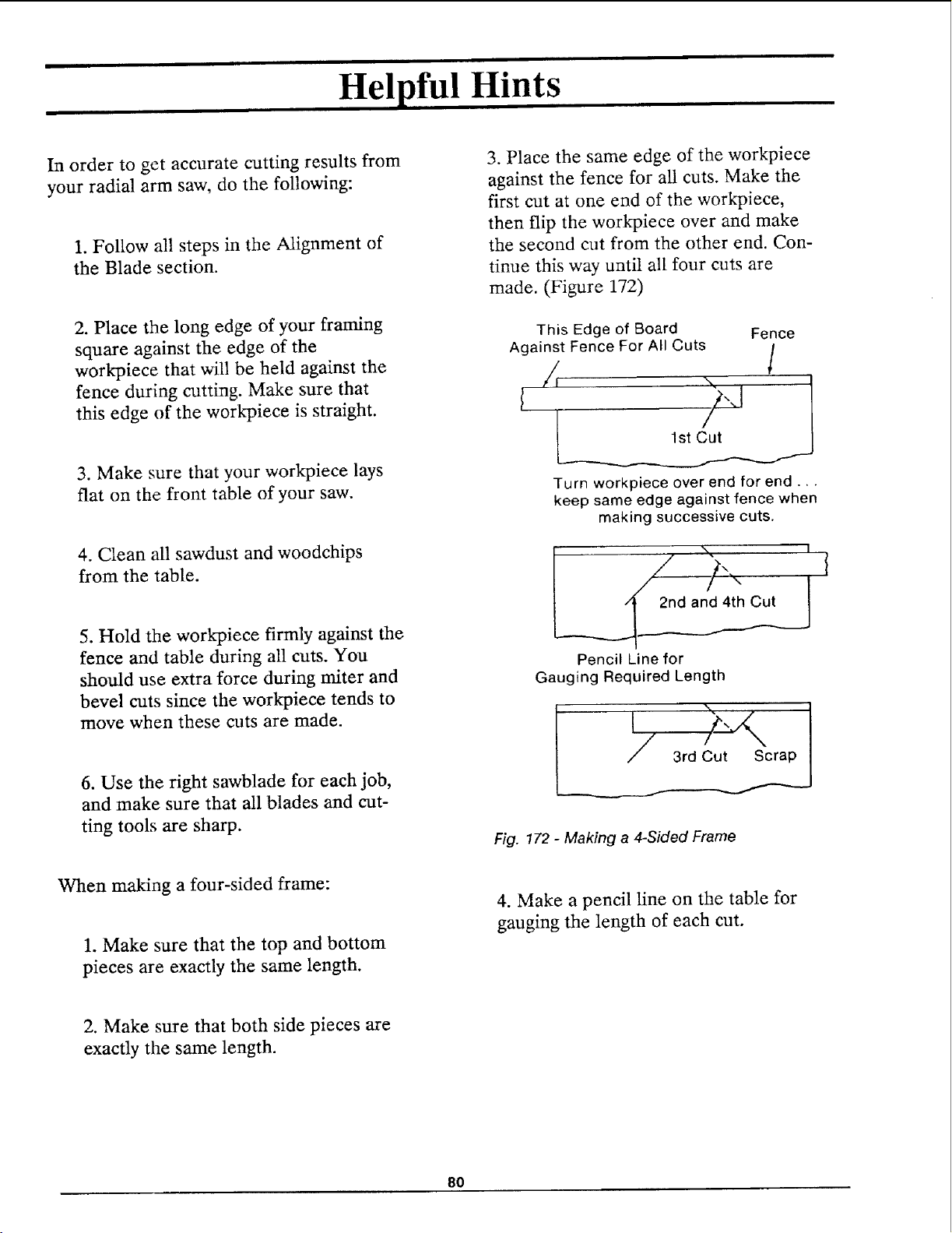
Helpful Hints
In order to get accurate cutting results from
your radial arm saw, do the following:
1. Follow all steps in the Alignment of
the Blade section.
2. Place the long edge of your framing
square against the edge of the
workpiece that will be held against the
fence during cutting. Make sure that
this edge of the work_iece is straight.
3. Make sure that your workpiece lays
flat on the front table of your saw.
4. Clean all sawdust and woodchips
from the table.
5. Hold the workpiece firmly against the
fence and table during all cuts. You
should use extra force during miter and
bevel cuts since the workpiece tends to
move when these cuts are made.
6. Use the right sawblade for each job,
and make sure that all blades and cut-
ting tools are sharp.
When making a four-sided frame:
1. Make sure that the top and bottom
pieces are exactly the same length.
3. Place the same edge of the workpiece
against the fence for all cuts. Make the
first cut at one end of the workpiece,
then flip the workpiece over and make
the second cut from the other end. Con-
tinue this way until all four cuts are
made. (Figure 172)
This Edge of Board Fence
Against Fence For All Cuts
/, /
Turn workpiece over end for end...
keep same edge against fence when
making successive cuts.
__ 2nd am
Pencil Line for
Gauging Required Length
Fig. !72 - Making a 4-Sided Frame
4. Make a pencil line on the table for
gauging the length of each cut.
2. Make sure that both side pieces are
exactly the same length.
8O
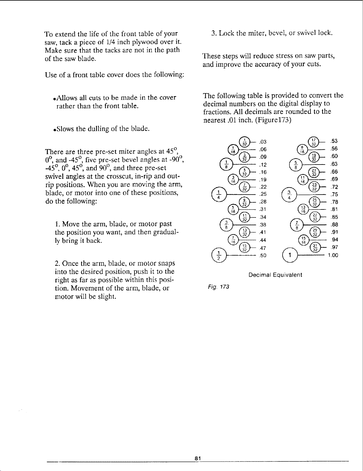
To extend the life of the front table of your
saw, tack a piece of 1/4 inch plywood over it.
Make sure that the tacks are not in the path
of the saw blade.
Use of a front table cover does the following:
3. Lock the miter, bevel, or swivel lock.
These steps will reduce stress on saw parts,
and improve the accuracy of your cuts.
.Allows all cuts to be made in the cover
rather than the front table.
.Slows the dulling of the blade.
There are three pre-set miter angles at 45 °,
0°, and -45 °, five pre-set bevel angles at -90 °,
-45 °, 0 °, 45 °, and 90 °, and three pre-set
swivel angles at the crosscut, in-rip and out-
rip positions. When you are moving the arm,
blade, or motor into one of these positions,
do the following:
1. Move the arm, blade, or motor past
the position you want, and then gradual-
ly bring it back.
2. Once the arm, blade, or motor snaps
into the desired position, push it to the
right as far as possible within this posi-
tion. Movement of the arm, blade, or
motor will be slight.
The following table is provided to convert the
decimal numbers on the digital display to
fractions. All decimals are rounded to the
nearest .01 inch. (Figure173)
.03
.06
.09
.12
.16
.19
.29
.25
.28
.31
.34
.38
,44
.47
,50
.60
.63
.66
.69
.94
M2J @._ .97
@ 1.00
Decimal Equivalent
Fig. 173
81
=
Maintaining Your Saw
General
WARNING: For your own safety,
turn power switch off and remove plug
from power source outlet before main-
taining or lubricating your saw.
When you receive your new Craftsman radial
saw, it requires no lubrication. The radial
saw has been partially aligned and all bear-
ings are lubricated and sealed for life. In
time, however, in order to keep your saw in
perfect working order and accurate, it will be
necessary to lubricate and realign. In fact
your radial saw needs more of a cleaning
than a lubrication.
Replacing Antikickback Pawls
Make sure the teeth of the antikiekbackpawL_
are always sharp. If they become dull they
must be replaced. With a 1/2 inch wrench or
socket remove the 5/16 hex nut and old
pawls. Reassemble new antikickback pawIs
and spreader to the bar. Check spreader for
proper alignment and correct if necessary.
(See Alignment of the Blade, Installing
Guard / Setting Spreader section.)
Cleaning
Periodically remove any heavy build-up of
sawdust that may accumulate on the saw.
The absorbing tendency of sawdust will draw
lubricants away from the areas where they
are needed. Clean the carriage bearings and
track surfaces. If packed sawdust and grease
accumulate repeatedly on carriage bearings
and track inspect the wipers for wear and
replace if necessary. (See Adjustments to
Compensate for Wear, Swivel Lock, later in
this section.)
To avoid motor damage the motor should be
blown out or vacuumed frequently to prevent
sawdust build-up which will interfere with
normal motor ventilation.
Lubrication
Your saw is precision built and should be
kept properly lubricated. Before describing
the various points which may periodically re-
quire lubrication, it is more important to first
mention the points which should not be lubri-
cated.
Do not lubricate the following:
• carriage ball bearings
.motor bearings
• area between the miter locking rings
and the column tube
The carriage ball bearings and motor bearings
are sealed ball bearings which require no
added lubrication.
Do lubricate the following, periodically, using
SAE No 10W-30 automotive engine oil:
.Apply a few drops of oil along the
swivel index pin and the bevel index pin
only if the pins have a tendency to
stick. Swivel to in-rip or out-rip for
easy access to the swivel indexpin.
Bevel to 45°and bevel index pin can be
easily accessed behind the yoke as il-
lustrated. (Figure 174)
82
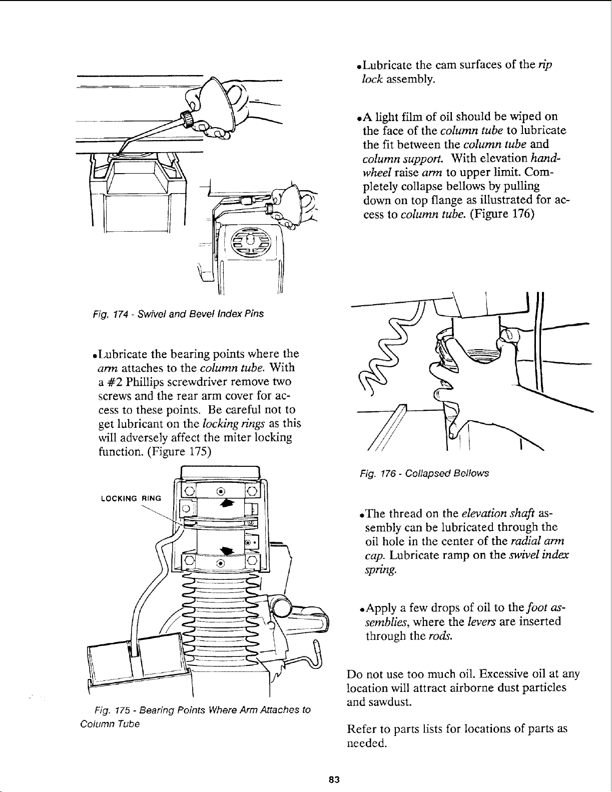
Fig. 174 - Swivel and Bevel Index Pins
• Lubricate the bearing points where the
arm attaches to the column tube. With
a -#2 Phillips screwdriver remove two
screws and the rear arm cover for ac-
cess to these points. Be careful not to
get lubricant on the locking rings as this
will adversely affect the miter locking
function. (Figure 175)
LOCKING RING
®
Fig. 175 - Bearing Points Where Arm Attaches to
Column Tube
• Lubricate the cam surfaces of the rip
lock assembly.
• A light film of oil should be wiped on
the face of the column tube to lubricate
the fit between the column tube and
column support. With elevation hand-
wheel raise arm to upper limit. Com-
pletely collapse bellows by pulling
down on top flange as illustrated for ac-
cess to column tube. (Figure 176)
Fig. 176 - Collapsed Bellows
.The thread on the elevation shaft as-
sembly can be lubricated through the
oil hole in the center of the radial arm
cap. Lubricate ramp on the swivel index
spring.
• Apply a few drops of oil to the foot as-
semblies, where the levers are inserted
through the rods.
Do not use too much oil. Excessive oil at any
location will attract airborne dust particles
and sawdust.
Refer to parts lists for locations of parts as
needed.
83
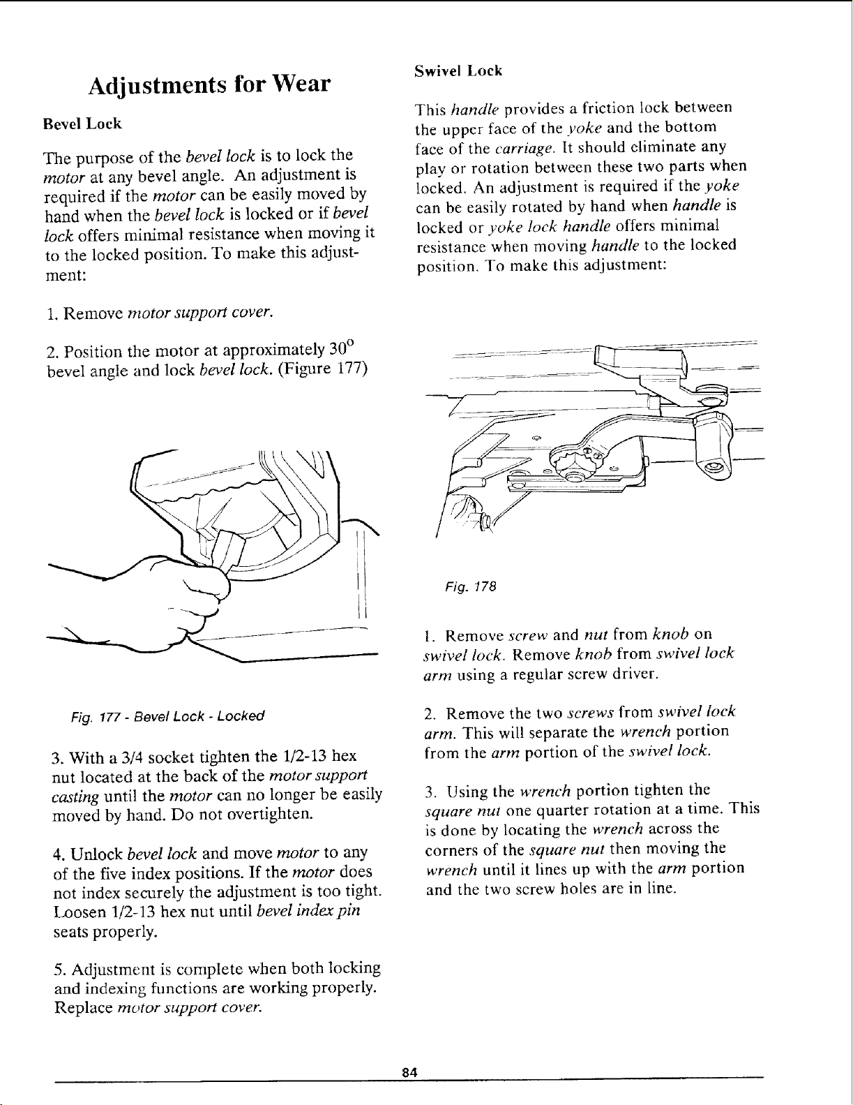
Adjustments for Wear
Bevel Lock
The purpose of the bevel lock is to lock the
motor at any bevel angle. An adjustment is
required if the motor can be easily moved by
hand when the bevel lock is locked or if bevel
lock offers minimal resistance when moving it
to the locked position. To make this adjust-
ment:
Swivel Lock
This handle provides a friction lock between
the upper face of the yoke and the bottom
face of the carriage. It should eliminate any
play or rotation between these two parts when
locked. An adjustment is required if the yoke
can be easily rotated by hand when handle is
locked or yoke lock handle offers minimal
resistance when moving handle to the locked
position. To make this adjustment:
1. Remove motor support cover.
2. Position the motor at approximately 30 °
bevel angle and lock bevel lock. (Figure 177)
Fig. 177 - Bevel Lock - Locked
3. With a 3/4 socket tighten the 1/2-13 hex
nut located at the back of the motor support
casting until the motor can no longer be easily
moved by hand. Do not overtighten.
4. Unlock bevel lock and move motor to any
of the five index positions. If the motor does
not index securely the adjustment is too tight.
Loosen 1/2-13 hex nut until bevel indexpin
seats properly.
5. Adjustment is complete when both locking
and indexing functions are working properly.
Replace motor support cover.
Fig. 178
l. Remove screw and nut from knob on
swivel lock. Remove knob from swivel lock
arm using a regular screw driver.
2. Remove the two screws from swivel lock
arm. This will separate the wrench portion
from the arm portion of the swivel lock.
3. Using the wrench portion tighten the
square nut one quarter rotation at a time. This
is done by locating the wrench across the
corners of the square nut then moving the
wrench until it lines up with the arm portion
and the two screw holes are in line.
84
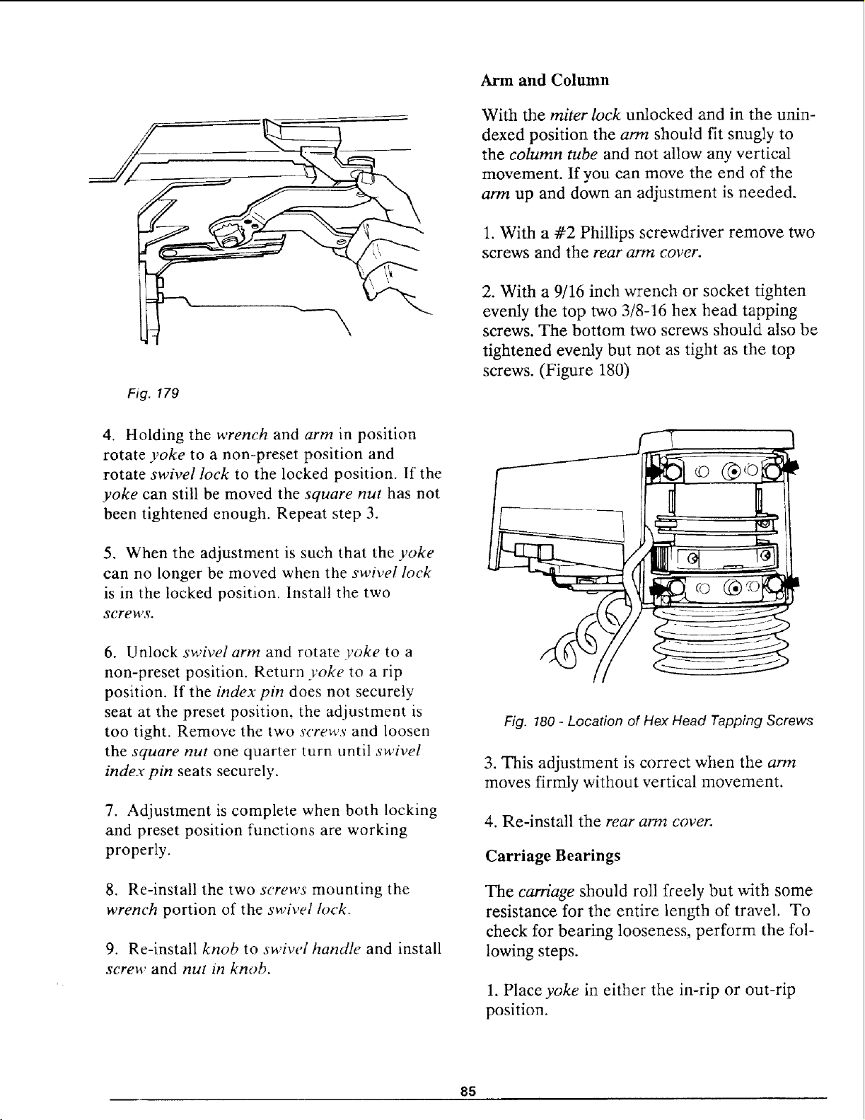
Fig. 179
Arm and Column
With the miter lock unlocked and in the unin-
dexed position the arm should fit snugly to
the column tube and not allow any vertical
movement. If you can move the end of the
arm up and down an adjustment is needed.
1. With a #2 Phillips screwdriver remove two
screws and the rear arm cover.
2. With a 9/16 inch wrench or socket tighten
evenly the top two 3/8-16 hex head tapping
screws. The bottom two screws should also be
tightened evenly but not as tight as the top
screws. (Figure 180)
4. Holding the wrench and arm in position
rotate yoke to a non-preset position and
rotate swivel lock to the locked position. If the
yoke can still be moved the square nut has not
been tightened enough. Repeat step 3.
5. When the adjustment is such that the yoke
can no longer be moved when the swivel lock
is in the locked position. Install the two
screws.
6. Unlock swivel arm and rotate yoke to a
non-preset position. Return yoke to a rip
position. If the index pin does not securely
seat at the preset position, the adjustment is
too tight. Remove the two screws and loosen
the square nut one quarter turn until swivel
index pin seats securely.
7. Adjustment is complete when both locking
and preset position functions are working
properly.
8. Re-install the two screws mounting the
wrench portion of the swivel lock.
9. Re-install knob to swivel handle and install
screw and nut in knob.
>
>
>
Fig. 180 - Location of Hex Head Tapping Screws
3. This adjustment is correct when the arm
moves firmly without vertical movement.
4. Re-install the rear arm cover.
Carriage Bearings
The carriage should roll freely but with some
resistance for the entire length of travel. To
check for bearing looseness, perform the fol-
lowing steps.
1. Place yoke in either the in-rip or out-rip
position.
85
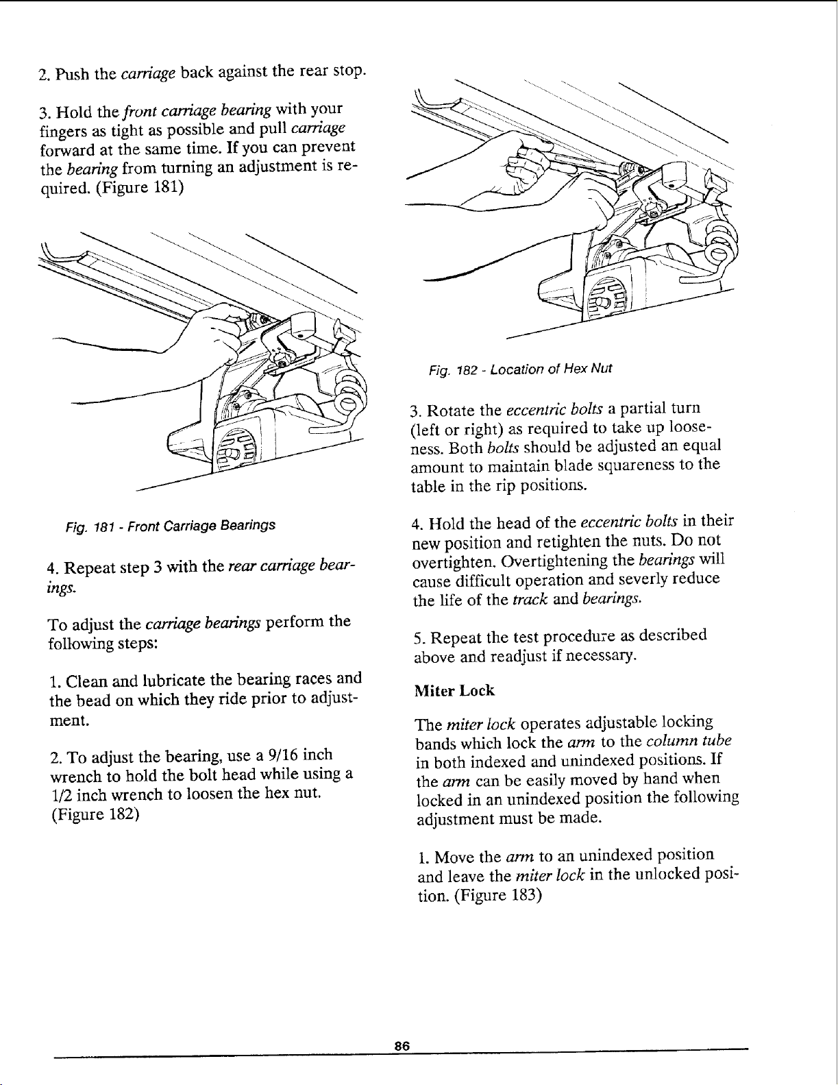
2. Push the carriage back against the rear stop.
3. Hold the front carriage bearing with your
fingers as tight as possible and pull carriage
forward at the same time. If you can prevent
the bearing from turning an adjustment is re-
quired. (Figure 181)
Fig. 181 - Front Carriage Bearings
4. Repeat step 3 with the rear carriage bear-
ings.
To adjust the carriage bearings' perform the
following steps:
1. Clean and lubricate the bearing races and
the bead on which they ride prior to adjust-
ment.
2. To adjust the bearing, use a 9/16 inch
wrench to hold the bolt head while using a
1/2 inch wrench to loosen the hex nut.
(Figure 182)
Fig. 182 - Location of Hex Nut
3. Rotate the eccentric bolts a partial turn
(left or right) as required to take up loose-
ness. Both bolts should be adjusted an equal
amount to maintain blade squareness to the
table in the rip positions.
4. Hold the head of the eccentric bolts in their
new position and retighten the nuts. Do not
overtighten. Overtightening the bearings will
cause difficult operation and severly reduce
the life of the track and bearings.
5. Repeat the test procedure as described
above and readjust if necessary.
Miter Lock
The miter lock operates adjustable locking
bands which lock the arm to the column tube
in both indexed and unindexed positions. If
the arm can be easily moved by hand when
locked in an unindexed position the following
adjustment must be made.
1. Move the arm to an unindexed position
and leave the miter lock in the unlocked posi-
tion. (Figure 183)
86
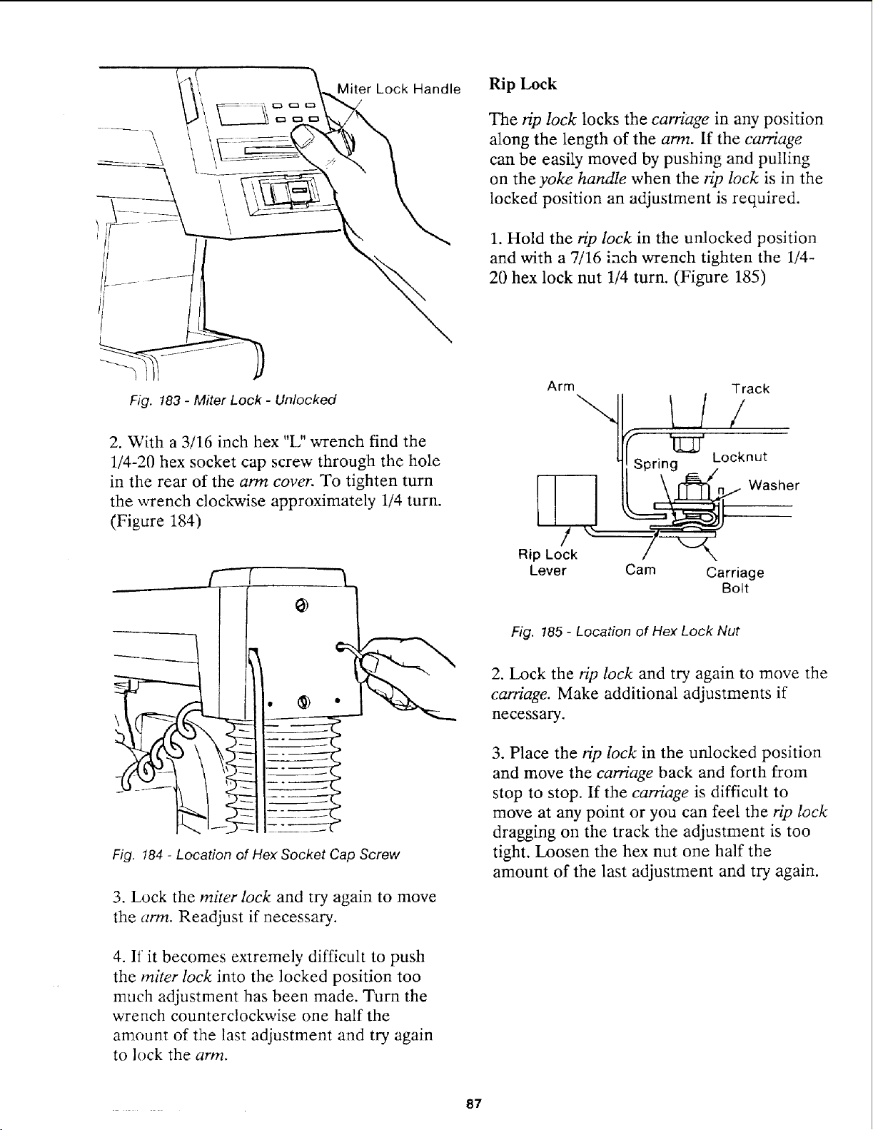
Rip Lock
The HI) lock locks the carriage in any position
along the length of the arm. If the carriage
can be easily moved by pushing and pulling
on the yoke handle when the rip lock is in the
locked position an adjustment is required.
1. Hold the rip lock in the unlocked position
and with a 7/16 inch wrench tighten the 1/4-
20 hex lock nut 1/4 turn. (Figure 185)
Fig. 183 - Miter Lock - Unlocked
2. With a 3/16 inch hex "L" wrench find the
1/4-20 hex socket cap screw through the hole
in the rear of the arm cover. To tighten turn
the wrench clockwise approximately 1/4 turn.
(Figure 184)
L
Fig. 184 - Location of Hex Socket Cap Screw
3. Lock the miter lock and try again to move
the arm. Readjust if necessary.
4. If it becomes extremely difficult to push
the miter lock into the locked position too
much adjustment has been made. Turn the
wrench counterclockwise one half the
amount of the last adjustment and try again
to lock the arm.
Arm
Spring
Rip Lock / ",,
Lever Cam Carriage
Bolt
Track
Locknut
Washer
Fig. !85 - Location of Hex Lock Nut
2. Lock the rip lock and try again to move the
carriage. Make additional adjustments if
necessary.
3. Place the rip lock in the unlocked position
and move the carriage back and forth from
stop to stop. If the carriage is difficult to
move at any point or you can feel the rip lock
dragging on the track the adjustment is too
tight. Loosen the hex nut one half the
amount of the last adjustment and try again.
87
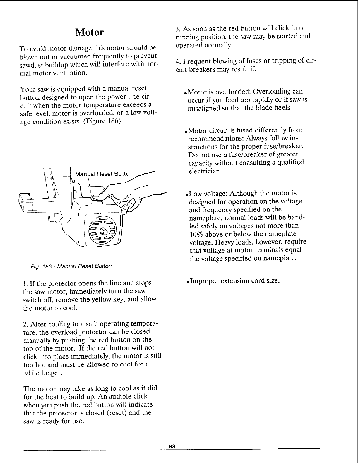
Motor
To avoid motor damage this motor should be
blown out or vacuumed frequently to prevent
sawdust buildup which will interfere with nor-
mal motor ventilation.
Your saw is equipped with a manual reset
button designed to open the power line cir-
cuit when the motor temperature exceeds a
safe level, motor is overloaded, or a low volt-
age condition exists. (Figure 186)
Manual Reset Button
\
Fig. 186 - Manual Reset Button
1. If the protector opens the line and stops
the saw motor, immediately turn the saw
switch off, remove the yellow key, and allow
the motor to cool.
2. After cooling to a safe operating tempera-
ture, the overload protector can be closed
manually by pushing the red button on the
top of the motor. If the red button will not
click into place immediately, the motor is still
too hot and must be allowed to cool for a
while longer.
The motor may take as long to cool as it did
for the heat to build up. An audible click
when you push the red button will indicate
that the protector is closed (reset) and the
saw is ready for use.
3. As soon as the red button will click into
running position, the saw may be started and
operated normally.
4. Frequent blowing of fuses or tripping of cir-
cuit breakers may result if:
• Motor is overloaded: Overloading can
occur if you feed too rapidly or if saw is
misaligned so that the blade heels.
.Motor circuit is fused differently from
recommendations: Always follow in-
structions for the proper fuse/breaker.
Do not use a fuse/breaker of greater
capacity without consulting a qualified
electrician.
.Low voltage: Although the motor is
designed for operation on the voltage
and frequency specified on the
nameplate, normal loads will be hand-
led safely on voltages not more than
10% above or below the nameplate
voltage. Heavy loads, however, require
that voltage at motor terminals equal
the voltage specified on nameplate.
,Improper extension cord size.
88
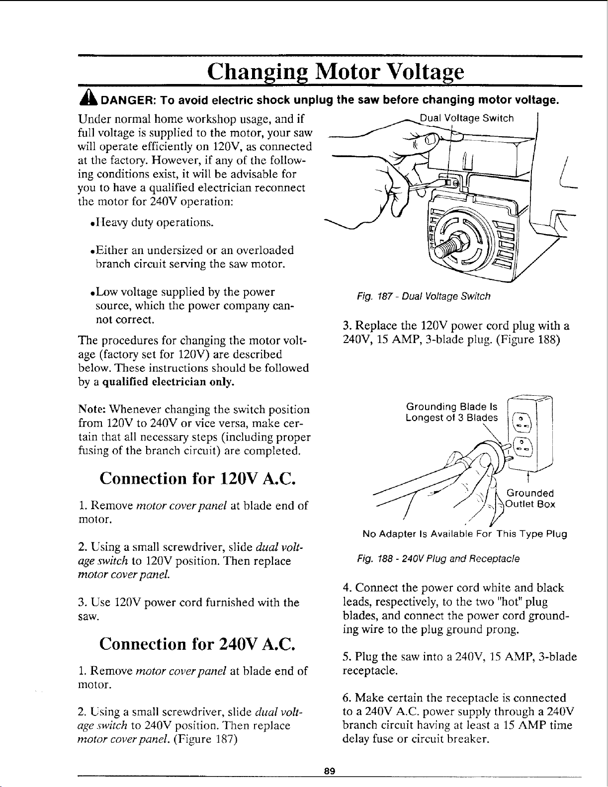
Changing Motor Voltage
_11_DANGER: To avoid electric shock unplug the saw before changing motor voltage.
Under normal home workshop usage, and if
full voltage is supplied to the motor, your saw
will operate efficiently on 120V, as connected
at the factory. However, if any of the follow-
ing conditions exist, it will be advisable for
you to have a qualified electrician reconnect
the motor for 240V operation:
Dual Voltage Switch
• I [eavy duty operations.
• Either an undersized or an overloaded
branch circuit serving the saw motor.
• Low voltage supplied by the power
source, which the power company can-
not correct.
The procedures for changing the motor volt-
age (factory set for 120V) are described
below. These instructions should be followed
by a qualified electrician only.
Fig. 187 - Dual Voltage Switch
3. Replace the 120V power cord plug with a
240V, 15 AMP, 3-blade plug. (Figure 188)
Note: Whenever changing the switch position
from 120V to 240V or vice versa, make cer-
tain that all necessary steps (including proper
fusing of the branch circuit) are completed.
Connection for 120V A.C.
1. Remove motor coverpanel at blade end of
motor.
2. Using a small screwdriver, slide dual volt-
age switch to 120V position. Then replace
motor cover panel.
3. Use 120V power cord furnished with the
saw.
Connection for 240V A.C.
1. Remove motor coverpanel at blade end of
motor.
2. Using a small screwdriver, slide dual volt-
age switch to 240V position. Then replace
motor cover panel. (Figure 187)
Grounding Blade Is
Longest of 3 Blades
Grounded
Outlet Box
No Adapter Is Available For This Type Plug
Fig. 188 - 240V Plug and Receptacle
4. Connect the power cord white and black
leads, respectively, to the two "hot" plug
blades, and connect the power cord ground-
ing wire to the plug ground prong.
5. Plug the saw into a 240V, 15 AMP, 3-blade
receptacle.
6. Make certain the receptacle is connected
to a 240V A.C. power supply through a 240V
branch circuit having at least a 15 AMP time
delay fuse or circuit breaker.
89
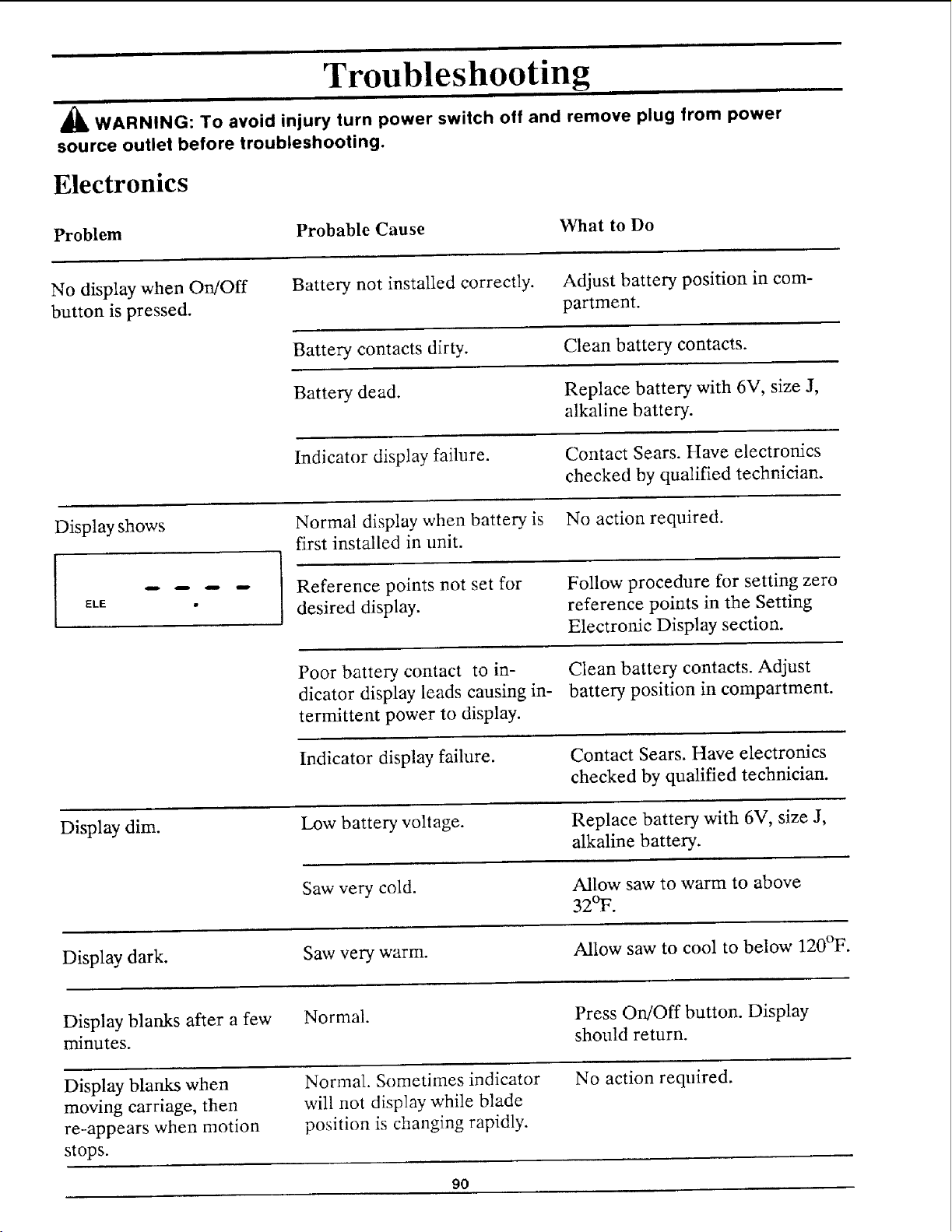
Troubleshooting
=
_I_ WARNING: To avoid injury turn power switch off and remove plug from power
source outlet before troubleshooting.
Electronics
Problem Probable Cause What to Do
No display when On/Off
button is pressed.
Battery not installed correctly. Adjust battery position in com-
partment.
Battery contacts dirty. Clean battery contacts.
Battery dead. Replace battery with 6V, size J,
alkaline battery.
Indicator display failure. Contact Sears. Have electronics
checked by qualified technician.
Display shows
Normal display when battery is No action required.
first installed in unit.
ELE •
Reference points not set for
desired display.
Follow procedure for setting zero
reference points in the Setting
Electronic Display section.
Poor battery contact to in- Clean battery contacts. Adjust
dicator display leads causing in- battery position in compartment.
termittent power to display.
Indicator display failure.
Contact Sears. Have electronics
checked by qualified technician.
Display dim.
Low battery voltage. Replace battery with 6V, size J,
alkaline battery.
Saw very cold.
Allow saw to warm to above
32°F.
Display dark. Saw very warm. Allow saw to cool to below 120_F.
Display blanks after a few Normal. Press On/Off button. Display
minutes, should return.
Display blanks when Normal. Sometimes indicator No action required.
moving carriage, then will not display while blade
re-appears when motion position is changing rapidly.
stops.
90
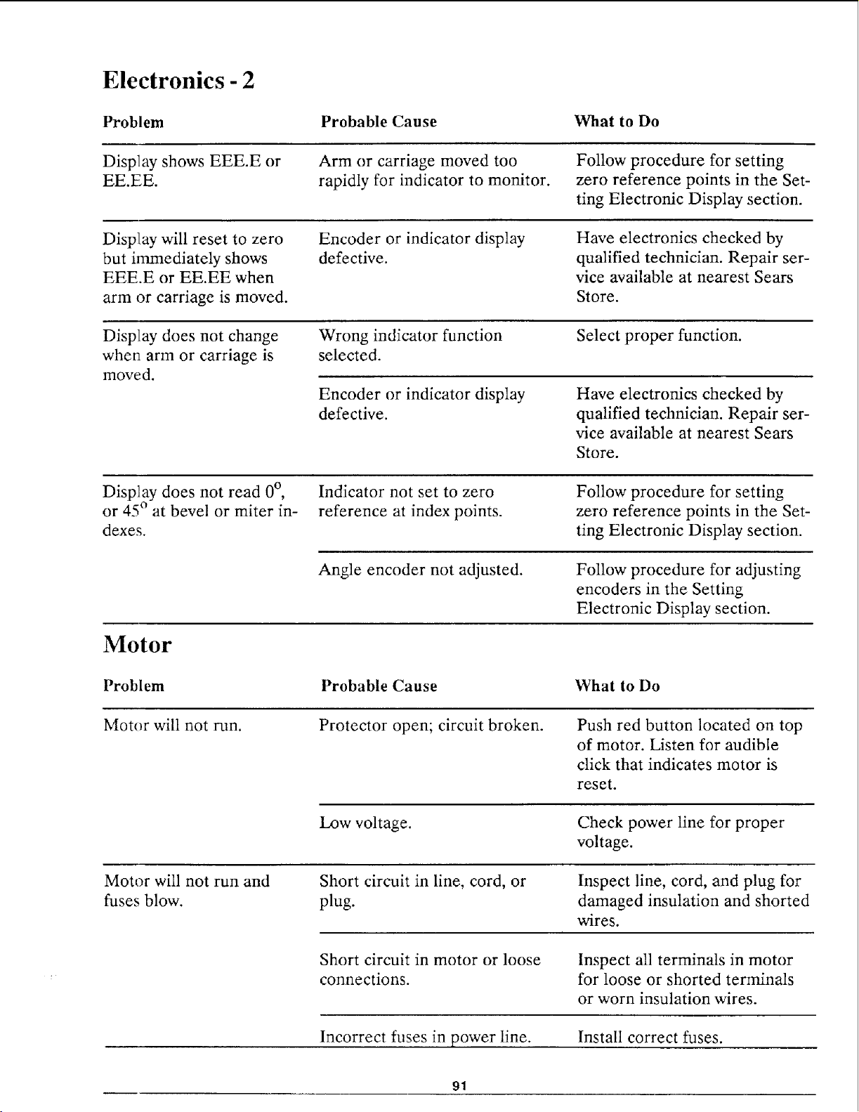
Electronics - 2
Problem Probable Cause
What to Do
Display shows EEE.E or
EE.EE.
Arm or carriage moved too Follow procedure for setting
rapidly for indicator to monitor, zero reference points in the Set-
ting Electronic Display section.
Display will reset to zero
but immediately shows
EEE.E or EE.EE when
arm or carriage is moved.
Encoder or indicator display
defective.
Have electronics checked by
qualified technician. Repair ser-
vice available at nearest Sears
Store.
Display does not change
when arm or carriage is
moved.
Wrong indicator function
selected.
Select proper function.
Encoder or indicator display
defective.
Have electronics checked by
qualified technician. Repair ser-
vice available at nearest Sears
Store.
Display does not read 0°, Indicator not set to zero
or 45 ° at bevel or miter in- reference at index points.
dexes.
Follow procedure for setting
zero reference points in the Set-
ting Electronic Display section.
Motor
Angle encoder not adjusted. Follow procedure for adjusting
encoders in the Setting
Electronic Display section.
Problem Probable Cause What to Do
Motor will not run.
Protector open; circuit broken. Push red button located on top
of motor. Listen for audible
click that indicates motor is
reset.
Low voltage.
Check power line for proper
voltage.
Motor will not run and
fuses blow.
Short circuit in line, cord, or
plug.
Inspect line, cord, and plug for
damaged insulation and shorted
wires.
Short circuit in motor or loose
connections.
Inspect all terminals in motor
for loose or shorted terminals
or worn insulation wires.
Incorrect fuses in power line. Install correct fuses.
91
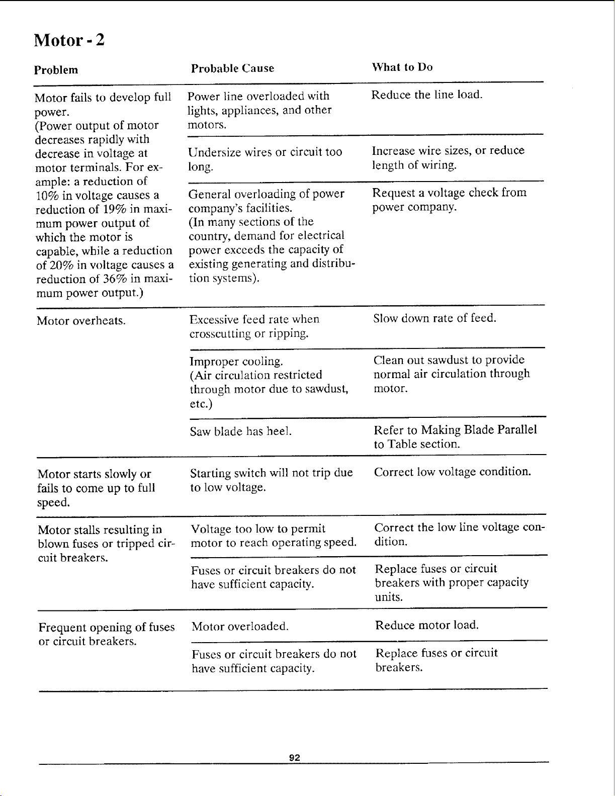
Motor - 2
Problem
Probable Cause
What to Do
Motor fails to develop full
power.
(Power output of motor
decreases rapidly with
decrease in voltage at
motor terminals. For ex-
ample: a reduction of
10% in voltage causes a
reduction of 19% in maxi-
mum power output of
which the motor is
capable, while a reduction
of 20% in w)ltage causes a
reduction of 36% in maxi-
mum power output.)
Power line overloaded with
lights, appliances, and other
motors.
Reduce the line load.
Undersize wires or circuit too
long.
Increase wire sizes, or reduce
length of wiring.
General overloading of power
company's facilities.
(In many sections of the
country, demand for electrical
power exceeds the capacity of
existing generating and distribu-
tion systems).
Request a voltage check from
power company.
Motor overheats.
Excessive feed rate when
crosscutting or ripping.
Slow down rate of feed.
Improper cooling.
(Air circulation restricted
through motor due to sawdust,
etc.)
Clean out sawdust to provide
normal air circulation through
motor.
Saw blade has heel. Refer to Making Blade Parallel
to Table section.
Motor starts slowly or
fails to come up to full
speed.
Starting switch will not trip due
to low voltage.
Correct low voltage condition.
Motor stalls resulting in
blown fuses or tripped cir-
cuit breakers.
Voltage too low to permit Correct the low line voltage con-
motor to reach operating speed, dition.
Fuses or circuit breakers do not Replace fuses or circuit
have sufficient capacity, breakers with proper capacity
units.
Frequent opening of fuses
or circuit breakers.
Motor overloaded.
Fuses or circuit breakers do not
have sufficient capacity.
Reduce motor load.
Replace fuses or circuit
breakers.
92
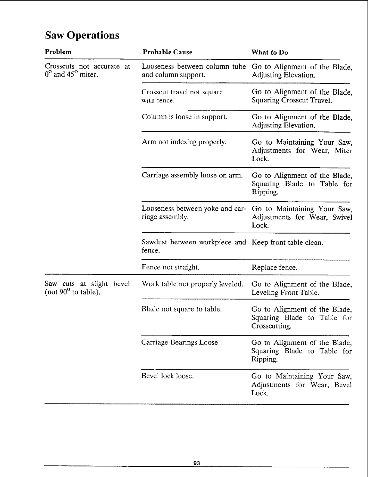
Saw Operations
Problem
Crosscuts not accurate at
0° and 45 ° miter.
Probable Cause
Looseness between column tube
and column support.
What to Do
Go to Alignment of the Blade,
Adjusting Elevation.
Crosscut travel not square
with fence.
Go to Alignment of the Blade,
Squaring Crosscut Travel.
Column is loose in support. Go to Alignment of the Blade,
Adjusting Elevation.
Arm not indexing properly.
Go to Maintaining Your Saw,
Adjustments for Wear, Miter
Lock.
Carriage assembly loose on arm. Go to Alignment of the Blade,
Squaring Blade to Table for
Ripping.
Looseness between yoke and car- Go to Maintaining Your Saw,
riage assembly. Adjustments for Wear, Swivel
Lock.
Sawdust between workpiece and Keep front table clean.
fence.
Fence not straight.
Replace fence.
Saw cuts at slight bevel
(not 90 ° to table).
Work table not properly leveled. Go to Alignment of the Blade,
Leveling Front Table.
Blade not square to table. Go to Alignment of the Blade,
Squaring Blade to Table for
Crosscutting.
Carriage Bearings Loose Go to Alignment of the Blade,
Squaring Blade to Table for
Ripping.
Bevel lock loose.
Go to Maintaining Your Saw,
Adjustments for Wear, Bevel
Lock.
93
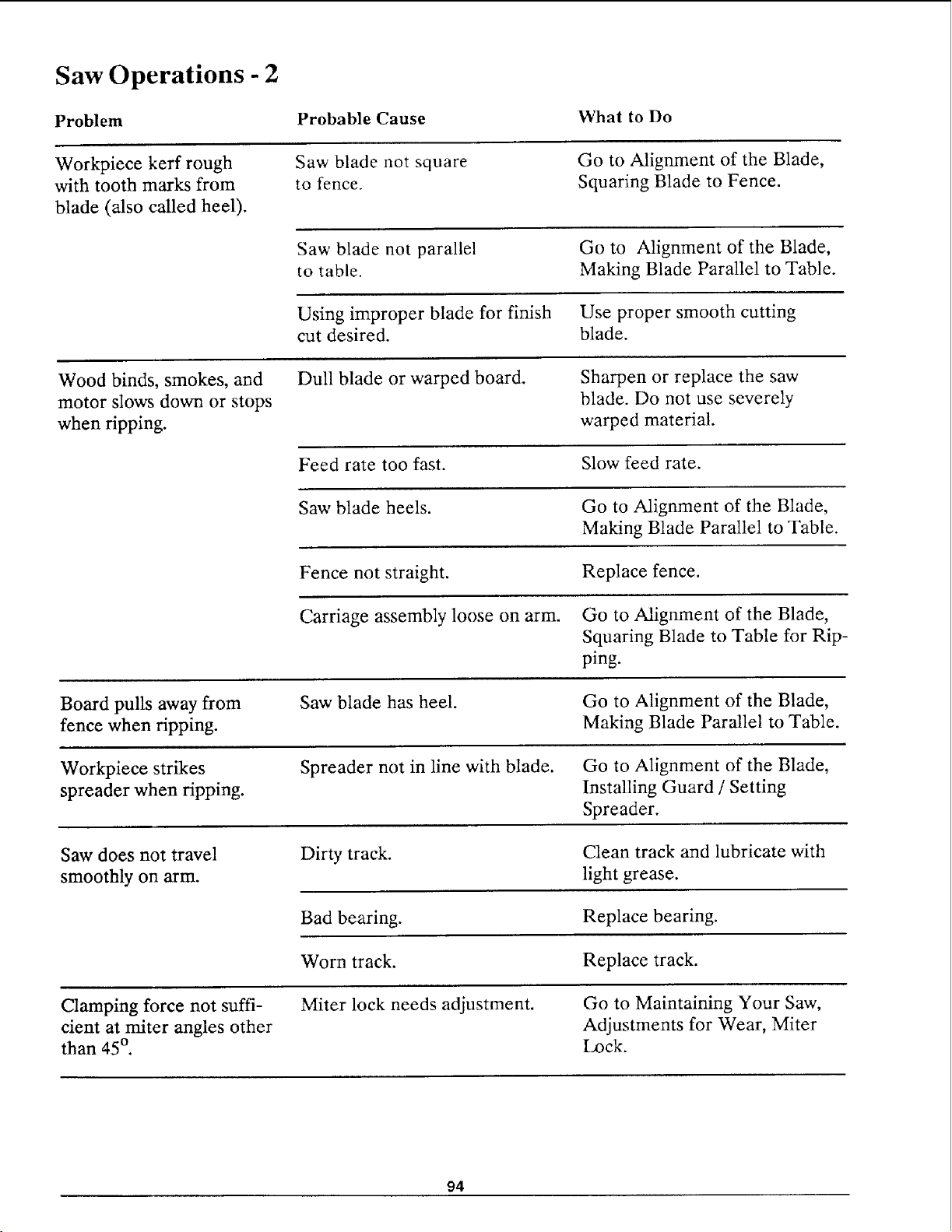
Saw Operations - 2
Problem Probable Cause
What to Do
Workpiece kerr rough
with tooth marks from
blade (also called heel).
Saw blade not square
to fence.
Go to Alignment of the Blade,
Squaring Blade to Fence.
Saw blade not parallel
to table.
Go to Alignment of the Blade,
Making Blade Parallel to Table.
Using improper blade for finish Use proper smooth cutting
cut desired, blade.
Wood binds, smokes, and Dull blade or warped board.
motor slows down or stops
when ripping.
Sharpen or replace the saw
blade. Do not use severely
warped material.
Feed rate too fast. Slow feed rate.
Saw blade heels. Go to Alignment of the Blade,
Making Blade Parallel to Table.
Fence not straight. Replace fence.
Carriage assembly loose on arm. Go to Alignment of the Blade,
Squaring Blade to Table for Rip-
ping.
Board pulls away from
fence when ripping.
Saw blade has heel.
Go to Alignment of the Blade,
Making Blade Parallel to Table.
Work_iece strikes
spreader when ripping.
Spreader not in line with blade. Go to Alignment of the Blade,
Installing Guard / Setting
Spreader.
Saw does not travel
smoothly on arm.
Dirty track.
Clean track and lubricate with
light grease.
Bad bearing. Replace bearing.
Worn track. Replace track.
Clamping force not suffi- Miter lock needs adjustment.
cient at miter angles other
than 45 ° .
Go to Maintaining Your Saw,
Adjustments for Wear, Miter
Lock.
94
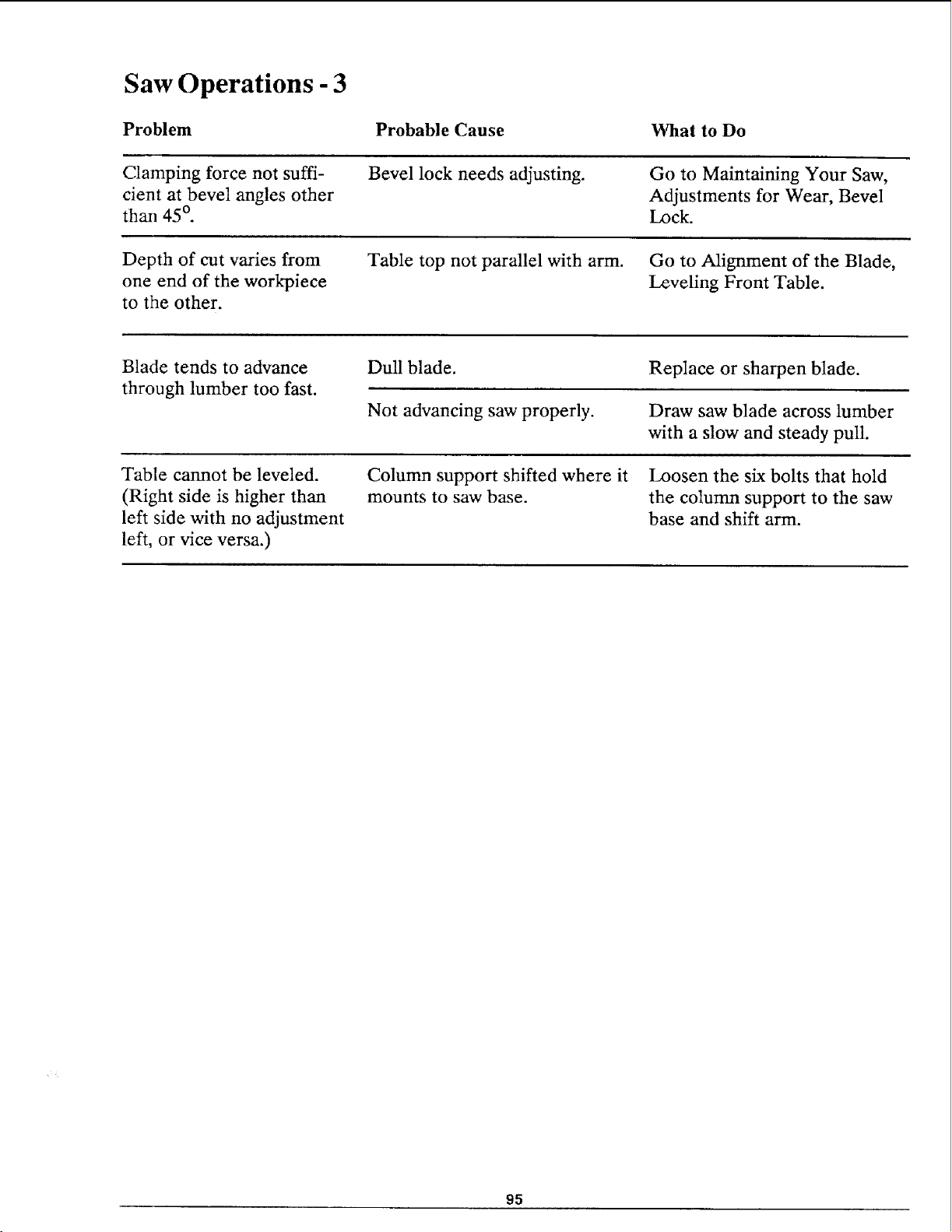
Saw Operations - 3
Problem Probable Cause What to Do
Clamping force not suffi-
cient at bevel angles other
than 45 °.
Bevel lock needs adjusting. Go to Maintaining Your Saw,
Adjustments for Wear, Bevel
Lock.
Depth of cut varies from
one end of the work_iece
to the other.
Table top not parallel with arm. Go to Alignment of the Blade,
Leveling Front Table.
Blade tends to advance
through lumber too fast.
Dull blade.
Not advancing saw properly.
Replace or sharpen blade.
Draw saw blade across lumber
with a slow and steady pull.
Table cannot be leveled.
(Right side is higher than
left side with no adjustment
left, or vice versa.)
Column support shifted where it
mounts to saw base.
Loosen the six bolts that hold
the column support to the saw
base and shift arm.
95
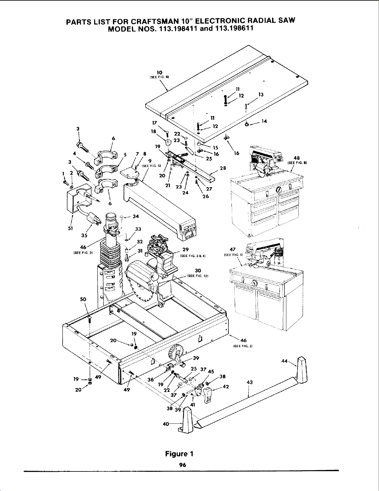
PARTS LIST FOR CRAFTSMAN 10" ELECTRONIC RADIAL SAW
MODEL NOS. 113.198411 and 113,198611
10
ISEE FIG. 6)
\
17
3 18_,,,_
4 \ 5 78
3 9
(SEE FIGS}
/
21
(SEE FIG, 2)
50
19
49
il
]_12 13
i
o
11
14
15
25
29 47
(SEE FIG. 3& 4) ISEE FIG. 9J
30
)
25 37 45
43
ptt42
38
Figure 1
96
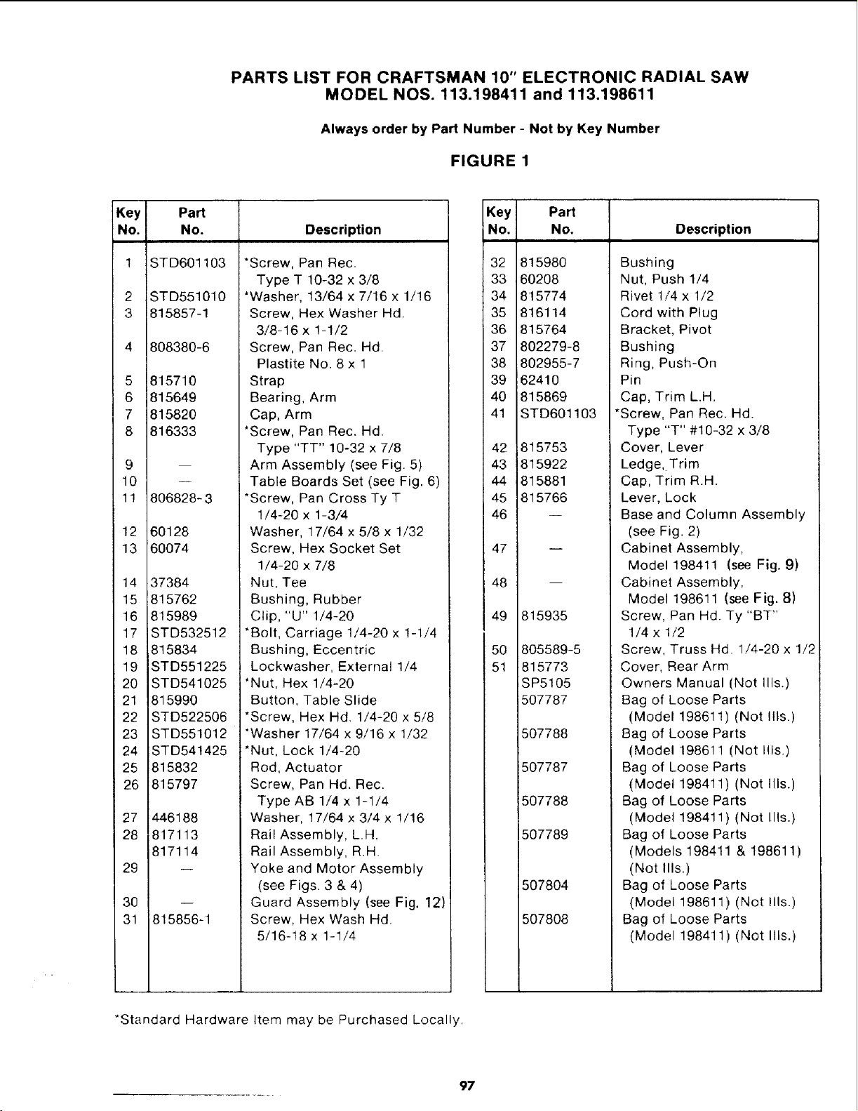
PARTS LIST FOR CRAFTSMAN 10" ELECTRONIC RADIAL SAW
MODEL NOS. 113.198411 and 113.198611
Always order by Part Number - Not by Key Number
FIGURE 1
Key Part
No. No. Description
1 STD601103 *Screw, Pan Rec.
2
3
5
6
7
8
STD551010
815857-1
8O838O-6
815710
815649
815820
816333
9
10
11 806828-3
12 60128
13 60074
14 37384
15 815762
16 815989
17 STD532512
18 815834
19 STD551225
20 STD541025
21 815990
22 STD522506
23 STD551012
24 STD54!425
25 815832
26 815797
27 446188
28 817113
817114
29
30
3! 815856-1
Type T 10-32 x 3/8
*Washer, 13/64 x 7/16 x 1/16
Screw, Hex Washer Hd.
3/8-16 x 1-1/2
Screw, Pan Rec. Hd
Plastite No. 8 x 1
Strap
Bearing, Arm
Cap, Arm
*Screw, Pan Rec. Hd.
Type "TT" 10-32 x 7/8
Arm Assembly (see Fig. 5)
Table Boards Set (see Fig. 6)
i *Screw, Pan Cross Ty T
1/4-20 x 1-3/4
Washer, 17/64 x 5/8 x 1/32
Screw, Hex Socket Set
1/4-20 x 7/8
Nut, Tee
Bushing, Rubber
Clip, "U" 1/4-20
*Bolt, Carriage 1/4-20 x 1-1/4
Bushing, Eccentric
Lockwasher, External 1/4
*Nut, Hex 1/4-20
Button, Table Slide
*Screw, Hex Hd 1/4-20 x 5/8
*Washer 17/64 x 9/16 x 1/32
*Nut, Lock 1/4-20
Rod, Actuator
Screw, Pan Hd. Rec.
Type AB 1/4 x 1-1/4
Washer, 17/64 x 3/4 x !/16
Rail Assembly, L.H.
Rail Assembly, R.H.
Yoke and Motor Assembly
(see Figs. 3 & 4)
Guard Assembly (see Fig. 12)
Screw, Hex Wash Hd.
5/16-18 x 1-1/4
Key Part
No. No. Description
32
33
34
35
36
37
38
39
40
41
42
43
44
45
46
47
48
49
5O
51
815980
60208
815774
816114
815764
802279-8
802955-7
62410
815869
STD601103
815753
815922
815881
815766
m
815935
805589-5
815773
SP5105
507787
507788
507787
507788
507789
507804
507808
Bushing
Nut, Push 1/4
Rivet 1/4 x 1/2
Cord with Plug
Bracket, Pivot
Bushing
Ring, Push-On
Pin
Cap, Trim L.H.
*Screw, Pan Rec. Hd.
Type "T" #10-32 x 3/8
Cover, Lever
Ledge, Trim
Cap, Trim R.H.
Lever, Lock
Base and Column Assembly
(see Fig. 2)
Cabinet Assembly,
Model 198411 (see Fig. 9)
Cabinet Assembly,
Model 198611 (see Fig. 8)
Screw, Pan Hd. Ty "BT"
1/4 x 1/2
Screw, Truss Hd. 1/4-20 x 1/2
Cover, Rear Arm
Owners Manual (Not Ills.)
Bag of Loose Parts
(Model 198611) (Not Ills.)
Bag of Loose Parts
(Model 19861! (Not Ills.)
Bag of Loose Parts
(Model 198411) (Not Ills.)
Bag of Loose Parts
(Model 198411) (Not Ills.)
Bag of Loose Parts
(Models 198411 & 198611)
(Not Ills.)
Bag of Loose Parts
(Model 198611) (Not Ills.)
Bag of Loose Parts
(Model 198411) (Not Ills.)
*Standard Hardware Item may be Purchased Locally,
97
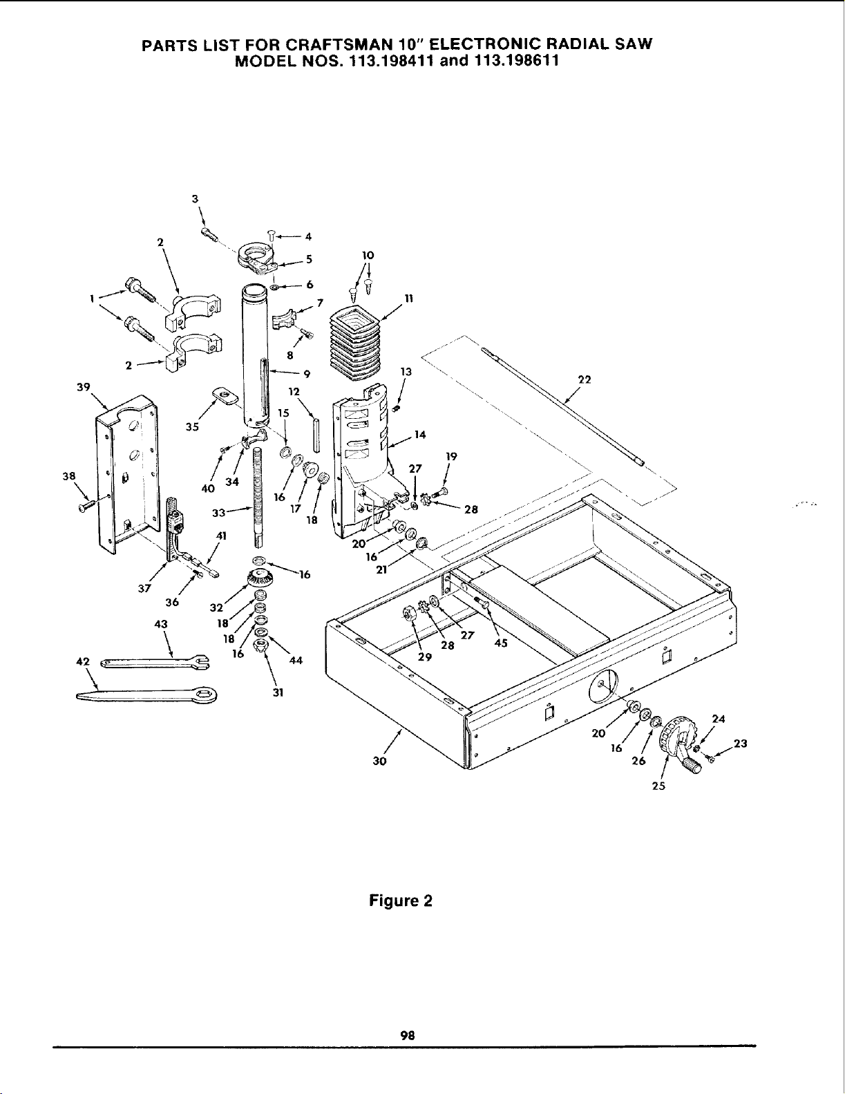
PARTS LIST FOR CRAFTSMAN 10" ELECTRONIC RADIAL SAW
MODEL NOS. 113.198411 and 113,198611
39
38
3
\
35
4O 1
18
41
lO
3O
13
/
2O
16
26
25
24
Figure 2
98
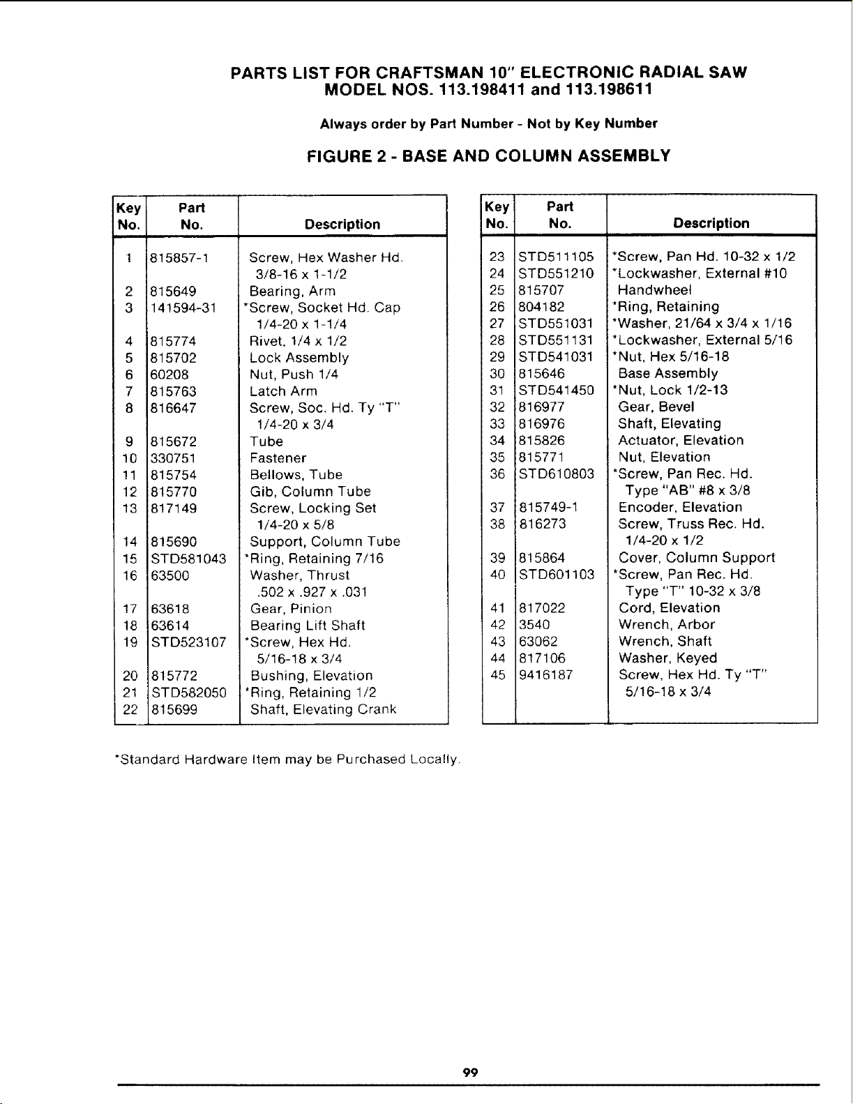
PARTS LIST FOR CRAFTSMAN 10" ELECTRONIC RADIAL SAW
MODEL NOS. 113.198411 and 113.198611
Always order by Part Number - Not by Key Number
FIGURE 2 - BASE AND COLUMN ASSEMBLY
Key
No. Description
1
2
3
4
5
6
7
8
Part
No.
815857-1
815649
141594-31
815774
815702
60208
815763
816647
9 815672
10 330751
11 815754
12 815770
13 817149
14 815690
15 STD581043
16 63500
17 63618
18 63614
19 STD523107
Screw, Hex Washer Hd.
3/8-16 x 1-1/2
Bearing, Arm
*Screw, Socket Hd. Cap
1/4-20 x 1-1/4
20
21
22
Rivet, 1/4 x 1/2
Lock Assembly
Nut, Push 1/4
Latch Arm
Screw, Soc. Hd. Ty "T"
1/4-20 x 3/4
Tube
Fastener
Bellows, Tube
Gib, Column Tube
Screw, Locking Set
1/4-20 x 5/8
Support, Column Tube
815772
STD582050
815699
*Ring, Retaining 7/16
Washer, Thrust
.502 x .927 x .031
Gear, Pinion
Bearing Lift Shaft
*Screw, Hex Hd.
5/16-18 x 3/4
Bushing, Elevation
*Ring, Retaining 1/2
Shaft, Elevating Crank
Key Part
No. No. Description
23
24
25
26
27
28
29
30
31
32
33
34
35
36
37
38
39
40
41
42
43
44
45
STD511105
STD551210
815707
804182
STD551031
STD551131
STD541031
815646
STD541450
816977
816976
815826
815771
STD610803
815749-1
816273
815864
STD601103
817022
3540
63062
817106
9416187
*Screw, Pan Hd. 10-32 x 1/2
*Lockwasher, External #10
Handwheel
*Ring, Retaining
*Washer, 21/64 x 3/4 x 1/16
*Lockwasher, External 5/16
*Nut, Hex 5/16-18
Base Assembly
*Nut, Lock 1/2-13
Gear, Bevel
Shaft, Elevating
Actuator, Elevation
Nut, Elevation
*Screw, Pan Rec. Hd.
Type "AB" #8 x 3/8
Encoder, Elevation
Screw, Truss Rec. Hd.
1/4-20 x 1/2
Cover, Column Support
*Screw, Pan Rec. Hd.
Type "T" 10-32 x 3/8
Cord, Elevation
Wrench, Arbor
Wrench, Shaft
Washer, Keyed
Screw, Hex Hd. Ty "T"
5/16-18 x 3/4
*Standard Hardware Item may be Purchased Locally.
99
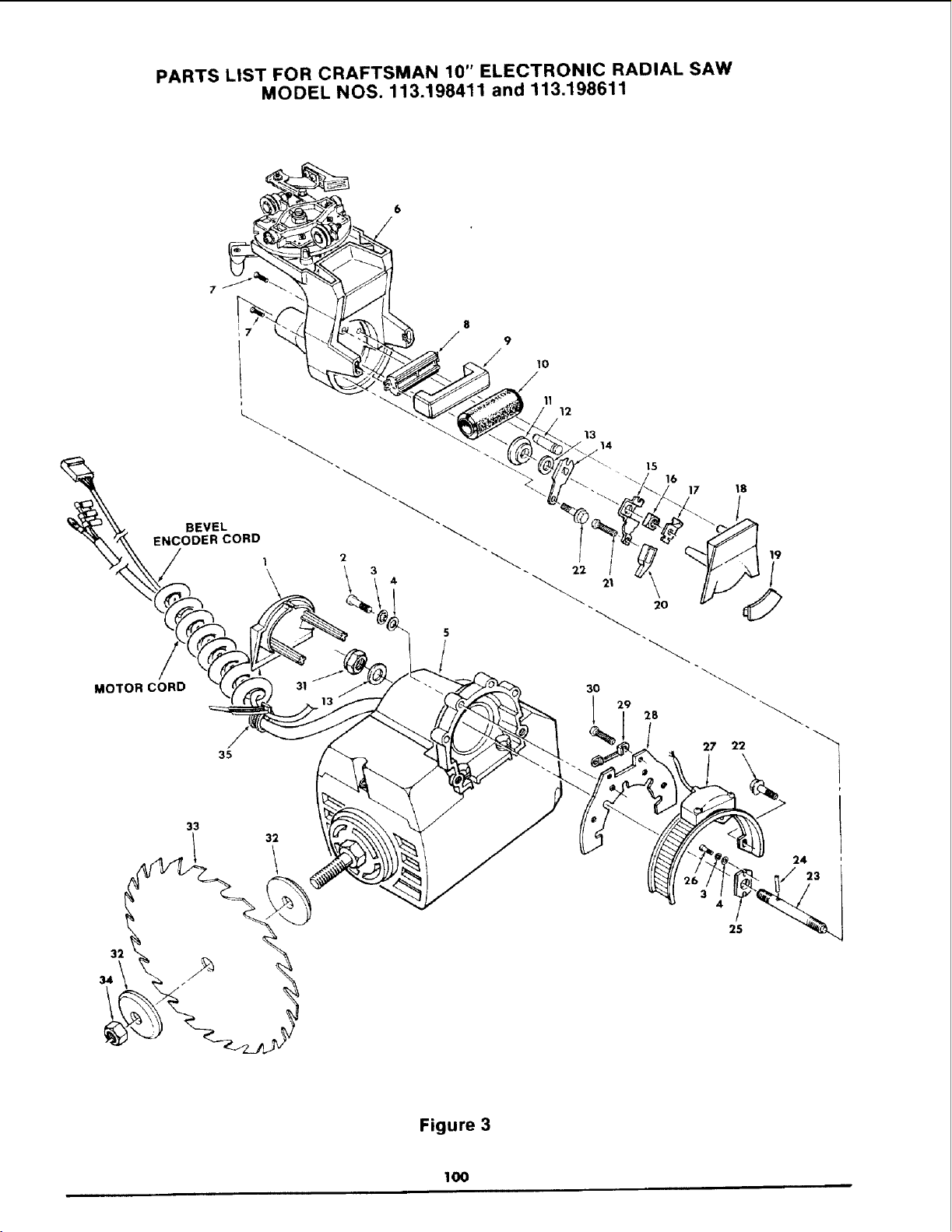
PARTS LIST FOR CRAFTSMAN 10" ELECTRONIC RADIAL SAW
MODEL NOS. 113.198411 and 113.198611
9
10
BEVEL
ENCODER CORD
2
MOTOR CORD 31
35
11
12
13
14
15
• 17 18
l
/
22
20
30
29 28
27 22
4
25
24
23
Figure 3
lO0
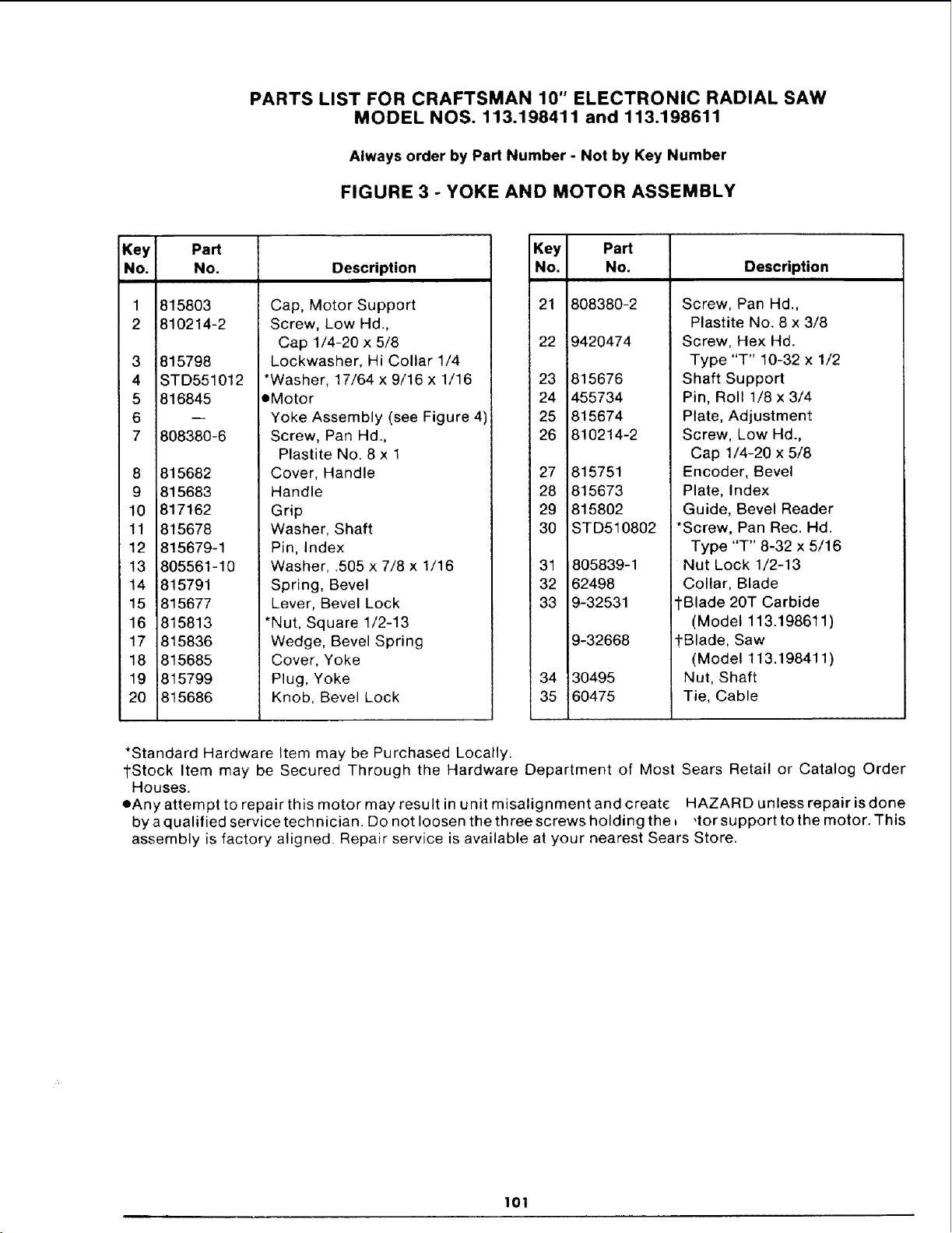
PARTS LIST FOR CRAFTSMAN 10" ELECTRONIC RADIAL SAW
MODEL NOS. 113.198411 and 113.198611
Always order by Part Number - Not by Key Number
FIGURE 3 - YOKE AND MOTOR ASSEMBLY
Key
No.
1
2
3
4
5
6
7
Part
No.
815803
810214-2
815798
STD551012
816845
808380-6
8 815682
9 815683
10 817162
11 815678
12 815679-1
13 805561-10
14 815791
15 815677
16 815813
17 815836
18 815685
19 815799
20 815686
Description
Cap, Motor Support
Screw, Low Hd.,
Cap 1/4-20 x 5/8
Lockwasher, Hi Collar 1/4
*Washer, 17/64 x 9/16 x 1/16
oMotor
Yoke Assembly (see Figure 4)
Screw, Pan Hd.,
Plastite No. 8 x 1
Cover, Handle
Handle
Grip
Washer, Shaft
Pin, Index
Washer, .505 x 7/8 x 1/16
Spring, Bevel
Lever, Bevel Lock
*Nut, Square 1/2-13
Wedge, Bevel Spring
Cover, Yoke
Plug, Yoke
Knob, Bevel Lock
Key Part
No. No. Description
21 808380-2 Screw, Pan Hd.,
22 9420474
23 815676
24 455734
25 815674
26 810214-2
27 815751
28 815673
29 815802
30 STD510802
31 805839-1
32 62498
33 9-32531
9-32668
34 30495
35 60475
Plastite No. 8 x 3/8
Screw, Hex Hd.
Type "T" 10-32 x 1/2
Shaft Support
Pin, Roll 1/8 x 3/4
Plate, Adjustment
Screw, Low Hd.,
Cap 1/4-20 x 5/8
Encoder, Bevel
Plate, Index
Guide, Bevel Reader
*Screw, Pan Rec. Hd.
Type "T" 8-32 x 5/16
Nut Lock 1/2-13
Collar, Blade
ll"Blade 20T Carbide
(Model 113.198611)
-i-Blade, Saw
(Model 113.198411)
Nut, Shaft
Tie, Cable
*Standard Hardware Item may be Purchased Locally.
1-Stock Item may be Secured Through the Hardware Department of Most Sears Retail or Catalog Order
Houses.
eAny attempt to repair this motor may result in unit misalignment and create HAZARD unless repair is done
by a qualified service technician. Do not loosen the three screws holding the b ,for support to the motor. This
assembly is factory aligned. Repair service is available at your nearest Sears Store.
101
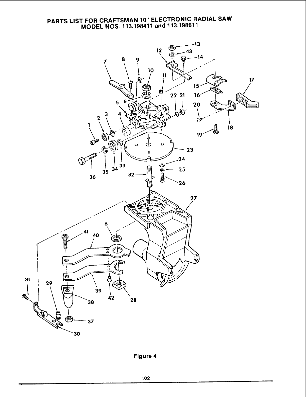
PARTS LIST FOR CRAFTSMAN 10" ELECTRONIC RADIAL SAW
MODEL NOS. 113.198411 and 113.198611
2
1 \
7
\
3
5 6
4
9
10
36
35
33
40
27
/
42
28
Figure 4
102

PARTS LIST FOR CRAFTSMAN 10" ELECTRONIC RADIAL SAW
MODEL NOS. 113.198411 and 113.198611
Always order by Part Number - Not by Key Number
FIGURE 4 - YOKE ASSEMBLY
Key Part
No. No. Description
1 810214-3 Screw, Low Hd.
2
3
4
5
6
7
8
STD315485
STD551031
817181
815689
STD551062
815827
STD600803
9 815817
10 STD541462
11 62636
12 815693
13 STD541425
14 273229
15 816497
16 815671
17 815804
18 815692
19 STD532507
20 808380-2
21 STD541231
Cap 5/16-18 x 7/8
*Bearing, Ball .3150 I.D.
*Washer, 21/64 x 5/8 x 1/32
Wiper, Track
Carriage
*Washer, .630 x !-1/8 x 3/32
Actuator, Rip
*Screw, Pan Rec. Hd.
Type "T" 8-32 x 3/8
Nut, Sq. Lock
*Nut, Lock 5/8-11
Nut, Sq. 1/4-20
Bracket, Rip Lock
*Nut, Lock 1/4-20
Screw, Hex Hd
Type "T" 1/4-20 x 1/2
Spring, Rip Lock
Cam, Rip Lock
Knob, Rip Lock
Lever, Rip Lock
*Bolt, Carriage 1/4-20 x 3/4
Screw, Pan Hd.,
Plastite No. 8 x 3/8
*Nut, Hex Jam 5/16-18
Key Part
No. No. Description
22 STD551131
23 815691
24 STD551012
25 815798
26 !810214-2
27
28
29
30
31
32
33
34
35
36
37
38
39
40
41
42
43
815645
109529
815679
815680
9420474
815694
STD551031
63777
60438
815807
STD541025
816988
816987
816986
STD512515
STD510602
62520
*Lockwasher, External 5/16
Ring, Yoke Index
*Washer, 17/64 x 7/16 x 1/32
Lockwasher, High Collar 1/4
Screw, Low Hd.,
Cap 1/4-20 x 5/8
Yoke
Nut, Square 5/8-11
Pin, Index
Spring, Swivel
Screw, Hex Type "T"
10-32 x 1/2
Stud, Yoke Clamp
Washer, 21/64 x 3/4 x 1/16
Bearing, Carriage
Washer, No. 2 Carriage
Bearing
Screw, Eccentric
*Nut, Hex 1/4-20
Knob, Swivel
Wrench, Adjustment
Actuator, Swivel
*Screw, Pan Hd. 1/4-20 x 1-1/2
*Screw, Pan Hd. 6-32 x 1/4
Spacer
*Standard Hardware Item may be Purchased Locally.
103
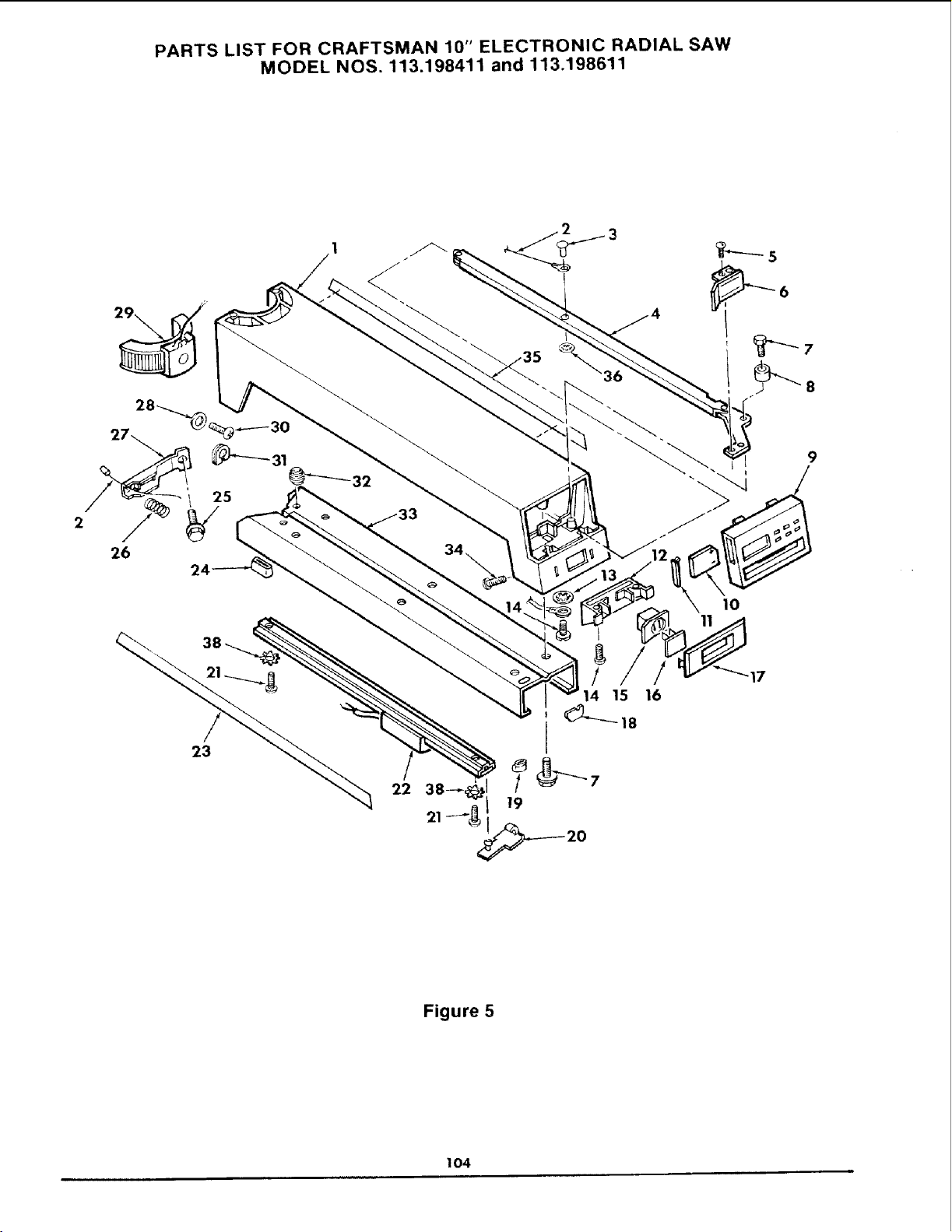
PARTS LIST FOR CRAFTSMAN 10" ELECTRONIC RADIAL SAW
MODEL NOS. 113.198411 and 113.198611
26
23
22
1o
17
16
Figure 5
104
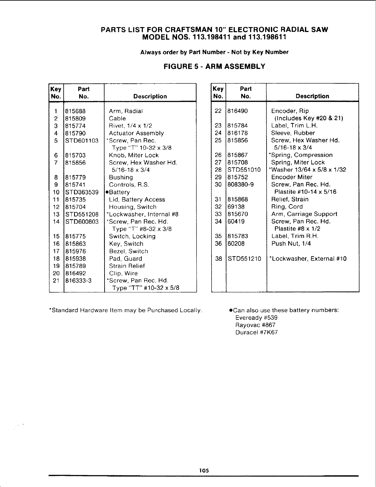
PARTS LIST FOR CRAFTSMAN 10" ELECTRONIC RADIAL SAW
MODEL NOS. 113.198411 and 113.198611
Always order by Part Number - Not by Key Number
FIGURE 5 - ARM ASSEMBLY
Key Part
No. No. Description
1
2
3
4
5
6
7
8
9
10
11
12
13
14
15
16
17
18
19
20
21
815688
815809
815774
815790
STD601103
815703
815856
815779
815741
STD363539
815735
815704
STD551208
STD600803
815775
815863
815976
815938
815789
816492
816333-3
Arm, Radial
Cable
Rivet, 1/4 x 1/2
Actuator Assembly
"Screw, Pan Rec.
Type "T" 10-32 x 3/8
Knob, Miter Lock
Screw, Hex Washer Hd.
5/16-18 x 3/4
Bushing
Controls, R.S.
oBattery
Lid, Battery Access
Housing, Switch
*Lockwasher, Internal #8
*Screw, Pan Rec. Hd.
Type "T" #8-32 x 3/8
Switch, Locking
Key, Switch
Bezel, Switch
Pad, Guard
Strain Relief
Clip, Wire
*Screw, Pan Rec. Hd.
Type "TT" #10-32 x 5/8
Key
No,
22
23
24
25
26
27
28
29
30
31
32
33
34
35
36
38
Part
No.
816490
815784
816178
815856
815867
815708
STD551010
815752
808380-9
815868
69138
815670
60419
815783
60208
STD551210
Description
Encoder, Rip
(Includes Key #20 & 21)
Label, Trim L.H.
Sleeve, Rubber
Screw, Hex Washer Hd.
5/16-18 x 3/4
*Spring, Compression
Spring, Miter Lock
*Washer 13/64 x 5/8 x 1/32
Encoder Miter
Screw, Pan Rec. Hd.
Plastite #10-14 x 5/16
Relief, Strain
Ring, Cord
Arm, Carriage Support
Screw, Pan Rec. Hd.
Plastite #8 x 1/2
Label, Trim R.H.
Push Nut, 1/4
*Lockwasher, External #10
*Standard Hardware Item may be Purchased Locally. oCan also use these battery numbers:
Eveready #539
Rayovac #867
Duracel#7K67
105
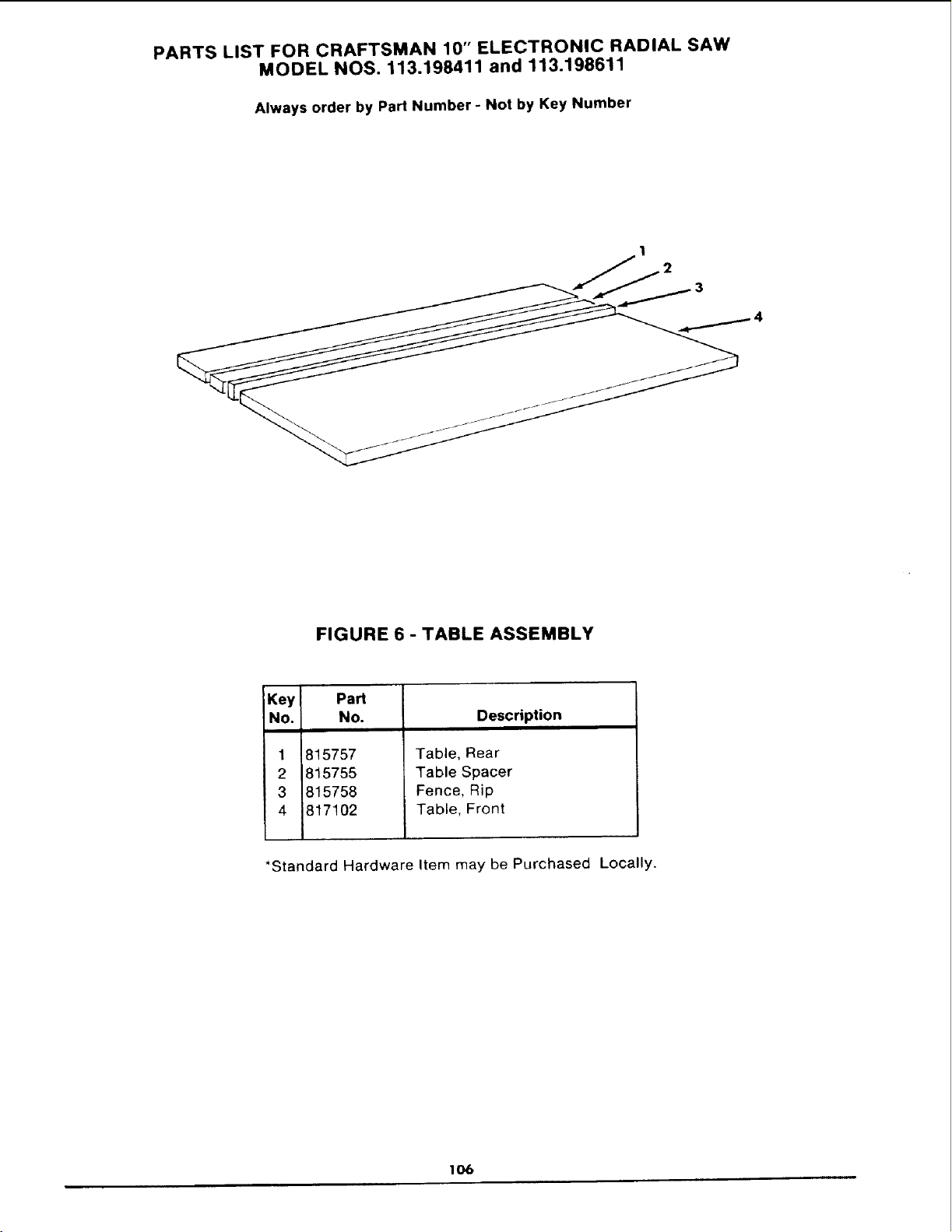
PARTS LIST FOR CRAFTSMAN 10" ELECTRONIC RADIAL SAW
MODEL NOS, 113.198411 and 113.198611
Always order by Part Number - Not by Key Number
FIGURE 6 - TABLE ASSEMBLY
Key Part
No. No.
1
2
3
4
815757
815755
815758
817102
Description
Table, Rear
Table Spacer
Fence, Rip
Table, Front
*Standard Hardware Item may be Purchased Locally.
lO6
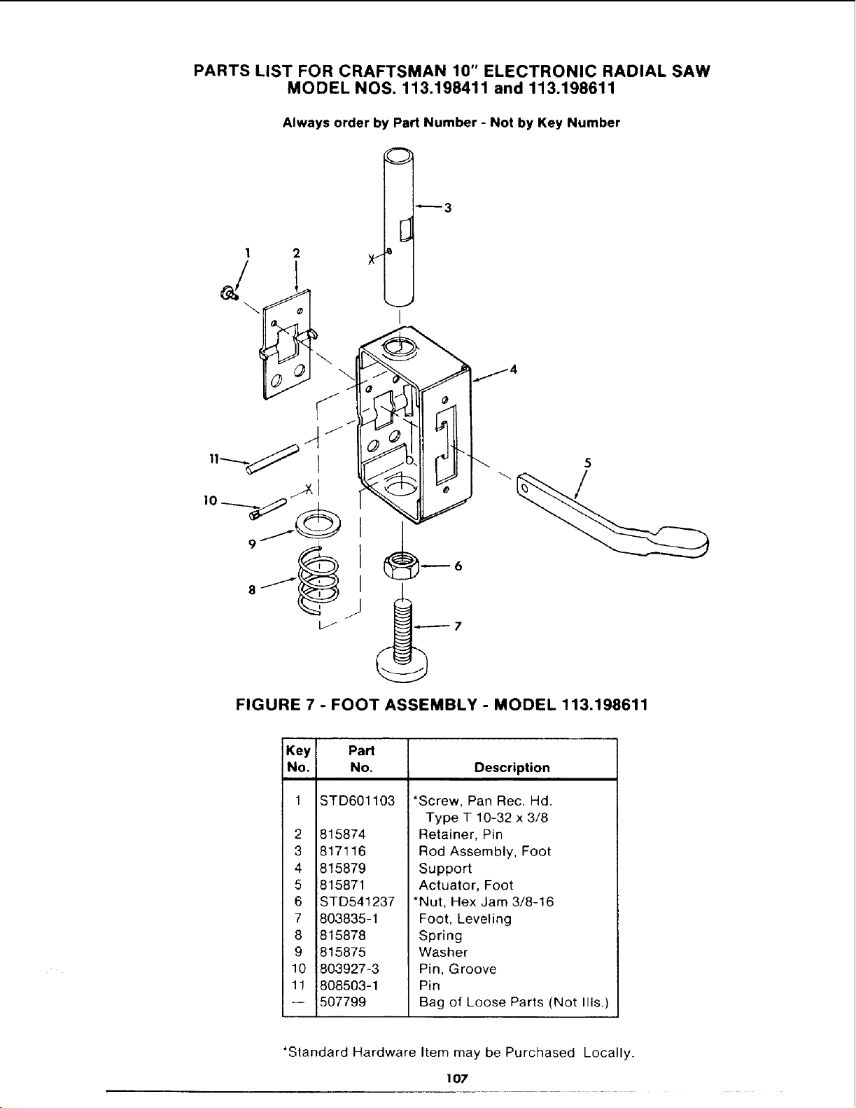
PARTS LIST FOR CRAFTSMAN 10" ELECTRONIC RADIAL SAW
MODEL NOS. 113.198411 and 113.198611
Always order by Part Number - Not by Key Number
1
J
2
I
[
!
_3
5
FIGURE 7 - FOOT ASSEMBLY - MODEL 113.198611
Key Part
No. No.
STD601103
2 815874
3 817116
4 815879
5 815871
6 STD541237
7 803835-1
8 815878
9 815875
10 803927-3
11 808503-1
-- 507799
Description
*Screw, Pan Rec. Hd.
Type T 10-32 x 3/8
Retainer, Pin
Rod Assembly, Foot
Support
Actuator, Foot
*Nut, Hex Jam 3/8-16
Foot, Leveling
Spring
Washer
Pin, Groove
Pin
Bag of Loose Parts (Not Ills.)
*Standard Hardware Item may be Purchased Locally.
107
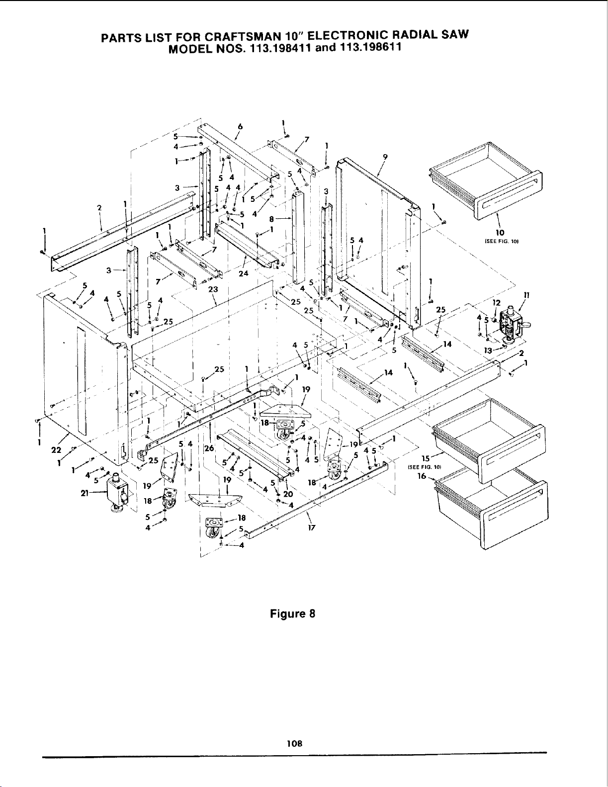
PARTS LIST FOR CRAFTSMAN 10" ELECTRONIC RADIAL SAW
MODEL NOS. 113.198411 and 113.198611
1
22
3
23
I 25 1
!i
i54
I1/ •
1
1
\\
1
Figure 8
108

PARTS LIST FOR CRAFTSMAN 10" ELECTRONIC RADIAL SAW
MODEL NOS. 113.198411 and 113.198611
Always order by Part Number - Not by Key Number
FIGURE 8 - CABINET ASSEMBLY FOR MODEL 113.198611
Key Part
No. No.
1 805589-5
2 815898
3 815892
4 STD541025
5 STD551225
6 815893
7 815890
8 815886
9 817151
10
11
12 i802392-36
13 i805529-5
14 i815888
Description
Screw, Truss Hd. 1/4-20 x 1/2
Skirt 44"
Support, Center Rear
*Nut, Hex 1/4-20
*Lockwasher, External 1/4
Support, Upper
Bracket, Stand Slide
Support, Front Center
Panel, Side R.H.
Drawer Assembly, 3 in.
(see Fig. 10)
Foot Assembly, R.H.
(see Fig. 7)
Spacer
Screw, Truss Hd.
1/4-20 x 1
Bracket, Center Slide
*Standard Hardware Item may be Purchased Locally.
Key Part
No. No. Description
15
16
17 815942
18 815896
19 815993
20 815991
21
22
23
24
25
26
817150
815889
815891
805529-4
816336
507802
Drawer Assembly 6 in,
(see Fig. 10)
Drawer Assembly 10 in.
(see Fig. 10)
Stiffener, Shelf
Caster
Support, Caster
Support, Under
Foot Assembly, L.H.
(see Fig. 7)
Panel, Side L.H.
Shelf, Lower 44 in.
Support, Lower
Screw, Slotted Truss Hd.
1/4-20 x 7/16
Stiffener - Shelf Rear
Bag of Loose Parts (Not Ills.)
109
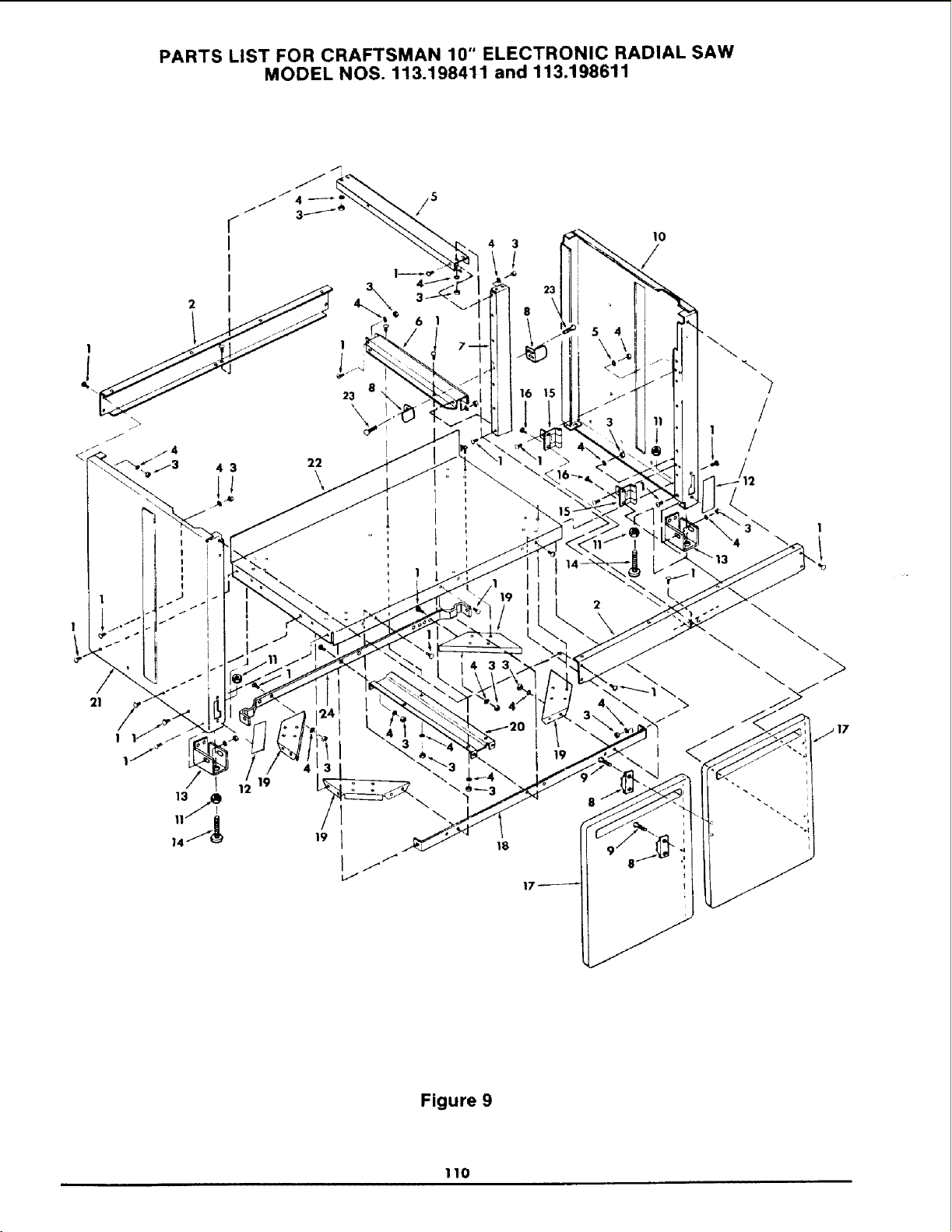
PARTS LIST FOR CRAFTSMAN 10" ELECTRONIC RADIAL SAW
MODEL NOS. 113.198411 and 113.198611
!
16
21
4 3 22
\
19
18
/
!
1
Figure 9
110

PARTS LIST FOR CRAFTSMAN 10" ELECTRONIC RADIAL SAW
MODEL NOS. 113.198411 and 113.198611
Always order by Part Number - Not by Key Number
FIGURE 9 - CABINET ASSEMBLY FOR MODEL 113.198411
Key
No.
1
2
3
4
5
6
7
8
9
Part
NO.
805589-5
815898
STD541025
STD551225
815893
815891
815886
815933
816274
10 817151
11 STD541237
12 816111
13 817108
Description
Screw, Truss Hd. 1/4-20 x 1/2
Skirt
*Nut, Hex 1/4-20
*Lockwasher, External 1/4
Support, Upper
Support, Lower
Support, Front Center
Catch, Magnetic
Screw, Pan Hd.
Plastite 6-10 x 1/2
Panel, R.H. Side
*Nut, Hex Jam 3/8-16
Cover
Spacer
Key Part
No. No.
14 803835-1
15 815934
16 816274-1
17 815882
18 815942
19 815993
2O 815991
21 817150
22 815889
23 STD600603
24 816336
-- 507794
Description
Foot, Leveling
Hinge, Door
Screw, Pan Hd.
Plastite 10-10 x 1/2
Door, Cabinet
Stiffener, Shelf
Support, Caster
Support, Under
Panel, L.H. Side
Shelf, Lower
*Screw, Pan Hd.
Type "T" 6-32 x 3/8
Stiffener - Shelf Rear
Bag of Loose Parts (Not Ills.)
*Standard Hardware Item may be Purchased Locally.
III
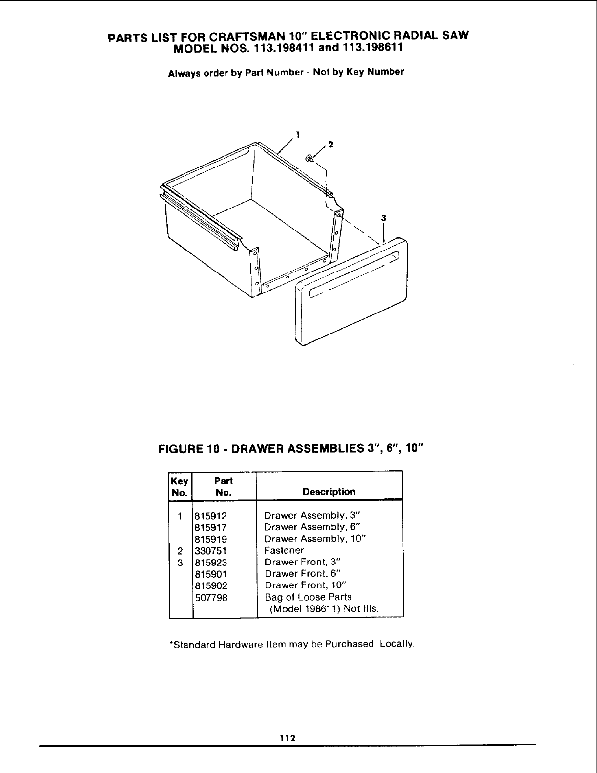
PARTS LIST FOR CRAFTSMAN 10" ELECTRONIC RADIAL SAW
MODEL NOS. 113.198411 and 113.198611
Always order by Part Number - Not by Key Number
1
3
\
FIGURE 10 - DRAWER ASSEMBLIES 3", 6", 10"
Key Part
No. No.
2
3
815912
815917
815919
330751
815923
815901
815902
507798
Description
Drawer Assembly, 3"
Drawer Assembly, 6"
Drawer Assembly, 10"
Fastener
Drawer Front, 3"
Drawer Front, 6"
Drawer Front, 10"
Bag of Loose Parts
(Model 198611) Not Ills.
*Standard Hardware Item may be Purchased Locally.
112
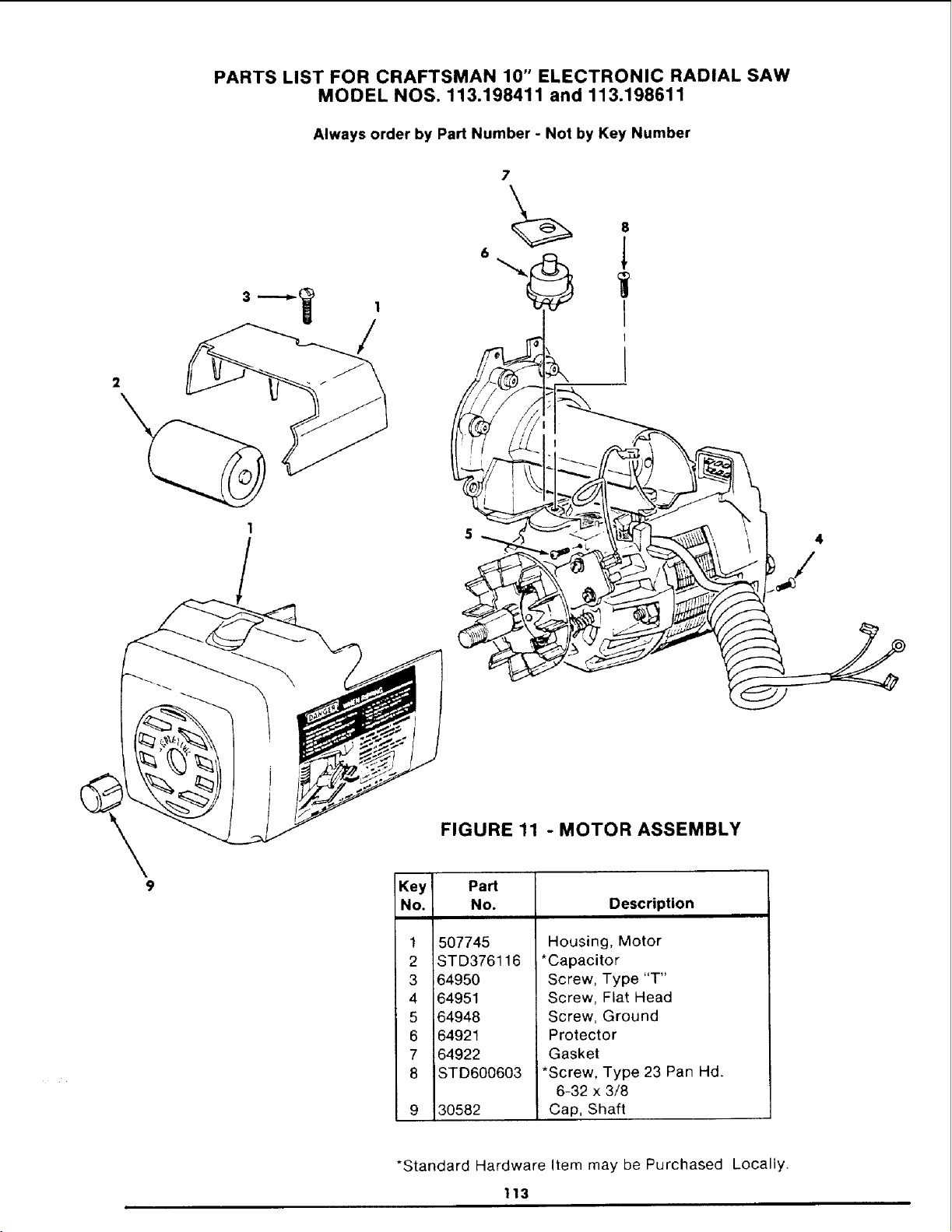
PARTS LIST FOR CRAFTSMAN 10" ELECTRONIC RADIAL SAW
MODEL NOS. 113.198411 and 113.198611
Always order by Part Number - Not by Key Number
/
2
Key
No.
1
2
3
4
5
6
7
8
FIGURE 11 - MOTOR ASSEMBLY
Part
No.
507745
STD376116
64950
64951
64948
64921
64922
STD600603
30582
Description
Housing, Motor
*Capacitor
Screw, Type "T"
Screw, Flat Head
Screw, Ground
Protector
Gasket
*Screw, Type 23 Pan Hd.
6-32 x 3/8
Cap, Shaft
*Standard Hardware Item may be Purchased Locally.
113
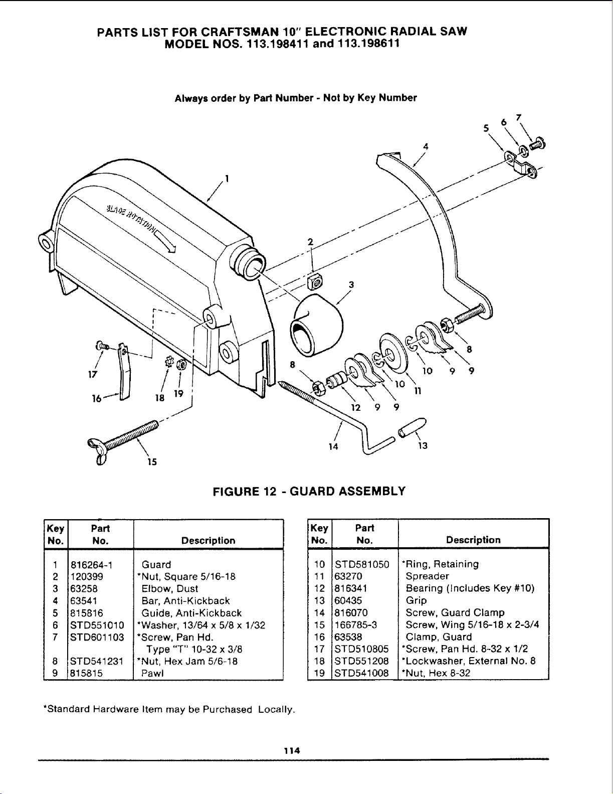
PARTS LIST FOR CRAFTSMAN 10" ELECTRONIC RADIAL SAW
MODEL NOS. 113.198411 and 113.198611
Always order by Part Number - Not by Key Number
5
\
1
17
16 18
14
10
11
12 9 9
13
8
9 9
FIGURE 12 - GUARD ASSEMBLY
Key
No.
1
2
3
4
5
6
7
8
9
p:rt
NO.
816264-1
120399
63258
63541
815816
STD551010
STD601103
STD541231
815815
Description
Guard
*Nut, Square 5/16-18
Elbow, Dust
Bar, Anti-Kickback
Guide, Anti-Kickback
*Washer, 13/64 x 5/8 x 1/32
*Screw, Pan Hd.
Type "T" 10-32 x 3/8
*Nut, Hex Jam 5/6-18
Pawl
Key Part
No. No.
10 STD581050
11 63270
12 816341
13 60435
14 816070
15 166785-3
16 63538
17 STD510805
18 STD551208
19 STD541008
Description
*Ring, Retaining
Spreader
Bearing (Includes Key #10)
Grip
Screw, Guard Clamp
Screw, Wing 5/16-18 x 2-3/4
Clamp, Guard
*Screw, Pan Hd. 8-32 x 1/2
"Lockwasher, External No. 8
*Nut, Hex 8-32
*Standard Hardware Item may be Purchased Locally.
114

NOTES

NOTES

NOTES

NOTES

NOTES
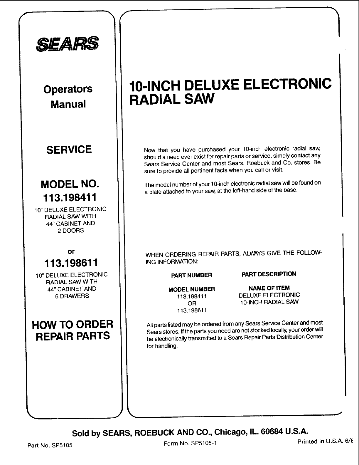
f
SEA/R,.
'N /"-
Operators
Manual
SERVICE
MODEL NO.
113.198411
10" DELUXE ELECTRONIC
RADIAL SAW WITH
44" CABINET AND
2 DOORS
or
113.198611
10" DELUXE ELECTRONIC
RADIAL SAW WITH
44" CABINET AND
6 DRAWERS
HOW TO ORDER
REPAIR PARTS
10-INCH DELUXE ELECTRONIC
RADIAL SAW
Now that you have purchased your 10-inch electronic radial saw,
should a need ever exist for repair parts or service, simply contact any
Sears Service Center and most Sears, Roebuck and Co. stores. Be
sure to provide all pertinent facts when you call or visit.
The model number of your 10-inch electronic radial saw will be found on
a plate attached to your saw, at the left-hand side of the base.
WHEN ORDERING REPAIR PARTS, ALWAYS GIVE THE FOLLOW-
ING INFORMATION:
PART NUMBER PART DESCRIPTION
MODEL NUMBER
113.198411
OR
113,198611
NAME OF ITEM
DELUXE ELECTRONIC
10-INCH RADIAL SAW
All parts listed may be ordered from any Sears Service Center and most
Sears stores. If the parts you need are not stocked locally, your order will
be electronically transmitted to a Sears Repair Parts Distribution Center
for handling.
Sold by SEARS, ROEBUCK AND CO., Chicago, IL. 60684 U.S.A.
Part No. SP5105 Form No. SP5105-1 Printed in U.S.A. 6/1_