Loading ...
Loading ...
Loading ...
11
underside of the terminal block (21), see Figure 10.
The unit voltage should be noted. Remove socket head
capscrew (47). Vertically lift the motor housing (6) from
seal plate (5) by lifting handle (13). Inspect square ring (27)
for damage or cuts. Remove the motor bolts and lift motor
stator from seal plate (5). Disconnect capacitor leads from
capacitor (9). Examine bearing (25) and replace if required. If
replacement is required, remove bearing (25) from motor shaft
using a wheel puller or arbor press, see Figure 11.
Check motor capacitor (9) with an Ohm meter by fi rst grounding
the capacitor by placing a screwdriver across both terminals
and then removing screwdriver. Connect Ohm meter (set on
high scale) to terminals. If needle moves to infi nity (∞) then
drifts back, the capacitor is good. If needle does not move or
moves to infi nity (∞) and does not drift back, replace capacitor
(9). Inspect motor winding for shorts and check resistance
values. Check rotor for wear. If rotor or the stator windings are
defective, the complete motor must be replaced.
Important ! - All parts must be clean before
reassembly.
F-4.2) Reassembly:
Bearings- When replacing bearing, be careful not to damage
the rotor or shaft threads. Clean the shaft thoroughly. Press
bearing (25) on the motor shaft, position squarely onto the
shaft applying force to the inner race of the bearing only, until
bearing seats against the retaining ring (24) (Included with
motor).
Motor- Slide lower bearing (25) and motor shaft squarely into
the seal plate (5) until bearing seats on the bottom. Place
stator over rotor, lining up motor bolts with holes in seal plate
(5). Position capacitor (9, single phase units) so that it will lay
on the opposite side of the cord entry bosses of the motor
housing (6). Reconnect capacitor leads. Torque motor tie bolts
to 17 in-lbs. Set square ring (27) in groove on seal plate (5).
F-4.3) Wiring Connections:
Check power cords (16) for cracks or damage and replace
if required (see Figure 12). Make internal wiring connections
which are independent of the terminal block as shown, using
connectors (48) and wire assemblies (49) as required.
DO NOT use wire nuts. Slip motor leads and ground wire
into fi berglass sleeve. Lower motor housing (6) down onto seal
plate (5) while aligning holes and stringing motor leads through
the cord entry bore. (Slipping cord inside a 1 ft. length of .5”
conduit makes this easier). Place socket head cap screws (47)
through seal plate (5) into motor housing (6) and torque to 60
in-lbs. Reconnect motor leads to the underside of the terminal
block (21) in Figure 13. Note that the pins are numbered
underneath the terminal block. Place o-ring (20) into groove
in terminal block and lubricate with dielectric oil. Press the
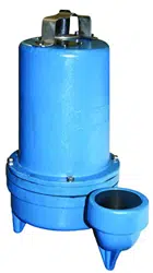
FIGURE 11
FIGURE 12
Power Cord (16)
Capscrew (11)
Lockwasher (12)
Compression Flange (16a)
Snap Ring (19)
O-ring (20)
Terminal Block (21)
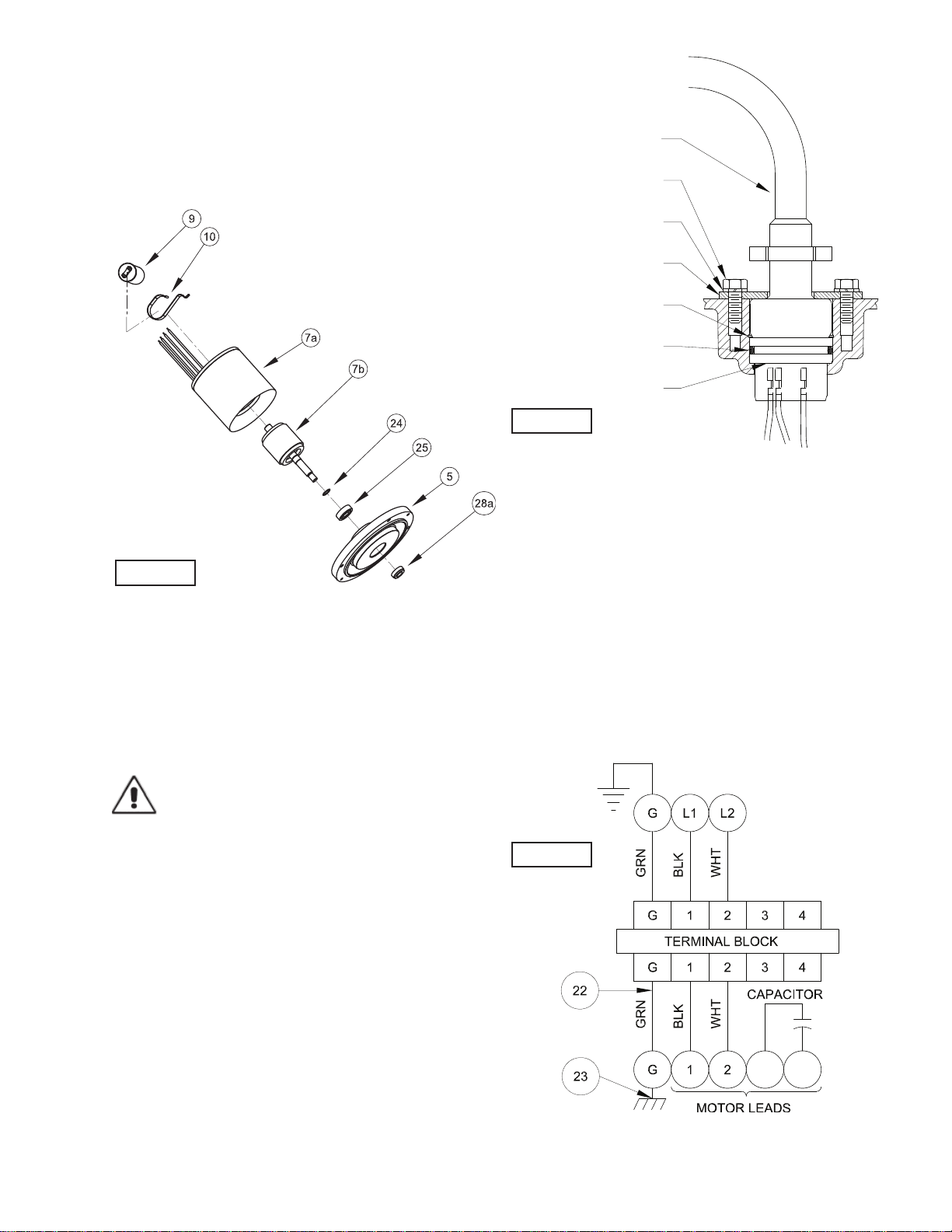
SINGLE PHASE - 240 VOLT AC (PSC)
FIGURE 13
Loading ...
Loading ...
Loading ...