Loading ...

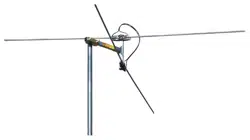
Fig. 5
Fig. 2
Fig. 1
FOR MODELS WITH REFLECTOR
BOOMS INSTALLED IN FACTORY
STEP 1. Remove antenna from carton and
unfold elements on reflector booms until
they lock into place. See Figure 1.
STEP 2. Unfold reflector booms until they
lock into place. See Figure 1.
FOR ALL MODELS
STEP 3. Unfold all other elements until they
lock into place. Be sure the elements are
locked into position and are flat and paral-
lel to each other. See Figure 2.
FOR TWO-PIECE BOOM MODELS
Remove nut and bolt from boom and slide
narrow end of boom into end of larger sec-
tion aligning bolt holes. See Figure 3. Re-
install bolt and nut, being sure to tighten
securely.
.
FOR MODELS PR-7042 & PR-7052
Repeat the step above for attaching front
and middle sections. Repeat the same pro-
cedure for attaching the rear section to the
middle. Then, remove the hex nuts and
washers from the top and bottom of the first
element holder studs on middle section.
See Figure 4. Place the phasing lines from
the rear section over the studs, one on top
and the other on bottom, and re-attach the
washers and hex nuts.
V
V
V
REFLECTOR
BOOM
MAST
CLAMPS
V
§
Fig. 4
FOR MODELS WITH BOOM BRACES
STEP 1. Assemble antenna using previ-
ous steps. Lay boom brace on top of an-
tenna with U-bolts on same side. Find the
bolt hole in the corner reflector and attach
brace with the bolt and nut provided. Swing
boom brace down toward the rear. Form a
"V" with the metal straps. Bolt the “V” to
each side of boom. See Figures 5 and 5A.
FOR MODELS PR-7032, PR-7037, PR-
7042, AND PR-7052 WITH PHASING
LINES
Remove hex nuts and washers from top
of first element holder studs. See Figure
6. Place phasing lines from front section
over studs, attach washers and hex nuts,
tighten securely.
YA- MODELS ONLY
ATTACHING COAX FOR YAGI MODELS
STEP 4. Attach cartridge housing bottom
to cartridge housing top already attached
to antenna by aligning tabs and snapping
into place. See Figure 7.
STEP 5. Slide weatherproof boot onto co-
axial cable and install connector. Attach
cable to downlead connection. Slide boot
over connector and boot collar.
CARTRIDGE HOUSING
TOP
CARTRIDGE
HOUSING BOTTOM
BOOT
COLLAR
75 OHM COAXIAL
CABLE (DOWNLEAD)
WEATHER BOOT
BOLT
Fig. 5A
Fig. 6
Fig. 7
MAIN
BOOM
BOOM
BRACE
PHASING
LINE
Fig. 3
STUD HOLDER
WASHER
NUT
REMOVE
FIRST
NUT
BOLT
REAR SECTION
MIDDLE SECTION
FRONT
DOWNLEAD JACK