
Loading ...
Loading ...
Loading ...
INSTALLATION INSTRUCTIONS
INSERT THE HEATER ASSEMBLY IN THE WALL CAN
Wire connections
STEP 4
1. Your heater has two connection wires on the bot-
tom. Your supply wire has two connection wires and a
supply ground wire.
A. Connect supply ground wire to grounding screw
in wall can (See Figures 8 and 9).
B. Connect one supply wire to one heater wire with
a wire connector (not included).
For 240 or 208 volts, it doesn’t matter which
heater wire. Both supply wires (black and white)
are hot. Wrap supply (white) wire with black tape
to identify it as hot (Figure 8).
240 Volt Figure 8
wall can
5
A
B
C
HOW TO CHANGE VOLTS (MULTI-VOLT MODEL CB103T ONLY)
Before installing your heater, it is extremely important you
verify your supply voltage. The multi-volt Com-Pak Bath
is 240 volts right out of the box. For 120 volts, you must
change the heater wiring slightly.
If you're replacing an existing heater, check the label of
the old heater and use the same voltage. If you need help,
review the "KNOW YOUR VOLTAGE" section, or call a
licensed electrician.
Select heater voltage
For 240 volts:
No need to do anything. The left side of your heater
assembly should look like Figure 3. The red wire is not
connected.
For 120 volts:
Remove the blue wire from terminal D and attach it to
terminal A. Then attach the unused red wire to terminal D
(see Figures 3 and 4). When you're done it should look like
Figure 4.
Proceed to STEP 4.
Check supply voltage
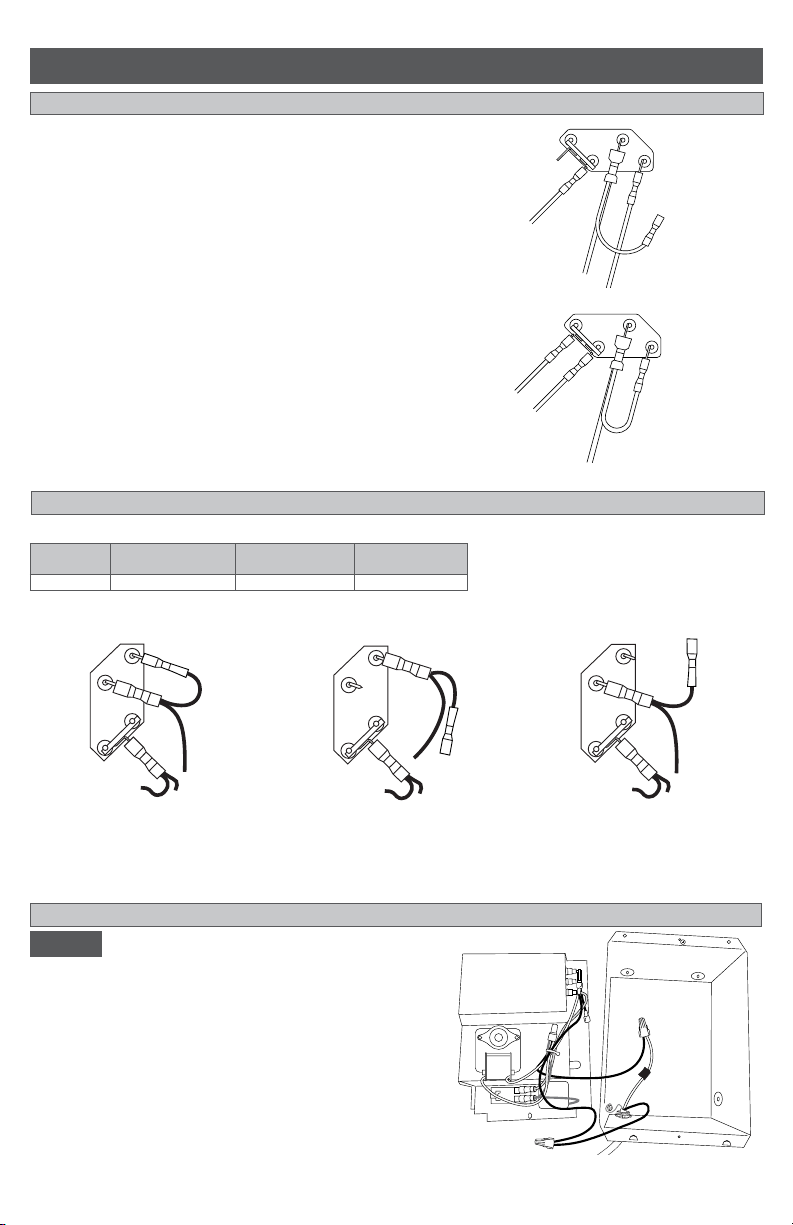
Multi-watt element wire connections
Multi-watt models are factory set to maximum wattage (Figure 5). You can lower the wattage by chang-
ing the element wire connections on the left side of the heater assembly (See below).
Figure 6
Figure 7
Volts
Maximum Wattage
Figure 5
Medium Wattage
Figure 6
Lowest Wattage
Figure 7
240V/208V 1300/975 800/600 500/375
Disconnect BLUE connector from ter-
minal C. Wrap loose wire end with elec-
trical tape. Move YELLOW connector at
terminal B to terminal C.
blue
connector
Disconnect BLUE connector at
terminal C. Wrap loose wire end
with electrical tape.
No change. tip: to remove
terminals easier, pull and
wiggle slightly back and forth
at the same time
HOW TO CHANGE WATTS (MULTI-WATT MODEL CB132T ONLY)
Do not disconnect the yellow connector from terminal A. Proceed to STEP 4.
Figure 5
blue
connector
removed
blue
connector
removed
White Wire
Black Wire
Blue Wire
Red Wire
White
Wire
Black Wire
Blue Wire
Red Wire
White Wire
Black Wire
Blue Wire
Red Wire
White
Wire
Black Wire
Blue Wire
Red Wire
B
C
D
A
Figure 3
Figure 4
Out of the box 240 volts
Changed to 120 volts
B
C
D
A
A
B
C
A
B
C
A
B
C
Loading ...
Loading ...
Loading ...