Loading ...
Loading ...
Loading ...
SERVICE AND ADJUSTMENTS
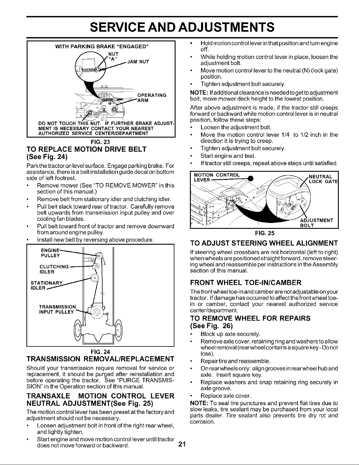
WITH PARKING BRAKE "ENGAGED"
NUT
JAM NUT
O pAT,NO
DO NOT TOUCH THIS NUT. IF FURTHER BRAKE ADJUST-
MENT IS NECESSARY CONTACT YOUR NEAREST
AUTHORIZED SERVICE CENTER/DEPARTMENT
FIG. 23
TO REPLACE MOTION DRIVE BELT
(See Fig. 24)
Parkthe tractor on level surface. Engage parking brake. For
assistance, there isa belt installation guide decal on bottom
side of left footrest.
Remove mower (See "TO REMOVE MOWER" in this
section of this manual.)
Remove belt from stationary idler and clutching idler.
Pull belt slacktoward rear oftractor. Carefully remove
belt upwards from transmission input pulley and over
cooling fan blades.
Pull belt toward front of tractor and remove downward
from around engine pulley.
Install new belt by reversing above procedure.
ENGINE_
PULLEY
CLUTCHING_
IDLER
STATIONARY
IDLER _
TRANSMISSION
INPUT PULLEY
FIG. 24
TRANSMISSION REMOVAL/REPLACEMENT
Should your transmission require removal for service or
replacement, it should be purged after reinstallation and
before operating the tractor. See "PURGE TRANSMIS-
SION" in the Operation section of this manual.
TRANSAXLE MOTION CONTROL LEVER
NEUTRAL ADJUSTMENT(See Fig. 25)
The motion control lever has been preset at the factory and
adjustment should not be necessary.
Loosen adjustment bolt in front of the right rear wheel,
and lightly tighten.
Start engine and move motion control lever until tractor
does not move forward or backward.
21
Hold motion control lever in that position and turn engine
off.
While holding motion control lever in place, loosen the
adjustment bolt.
Move motion control lever to the neutral (N) (lock gate)
position.
Tighten adjustment bolt securely.
NOTE: Ifadditional clearance is needed to get to adjustment
bolt, move mower deck height to the lowest position.
After above adjustment is made, if the tractor still creeps
forward or backward while motion control lever is in neutral
position, follow these steps:
Loosen the adjustment bolt.
Move the motion control lever 1/4 to 1/2 inch in the
direction it is trying to creep.
Tighten adjustment bolt securely.
Start engine and test.
If tractor still creeps, repeat above steps until satisfied.
MOTION CONTROL
,NEUTRAL
LOCK GATE
FIG. 25
TO ADJUST STEERING WHEEL ALIGNMENT
If steering wheel crossbars are not horizontal (left to right)
when wheels are positioned straight forward, remove steer-
ing wheel and reassemble per instructions in the Assembly
section of this manual.
FRONT WHEEL TOE-IN/CAMBER
The frontwheel toe-in and camber are not adjustable on your
tractor. If damage has occurred to affect the frontwheel toe-
in or camber, contact your nearest authorized service
center/department.
TO REMOVE WHEEL FOR REPAIRS
(See Fig. 26)
Block up axle securely.
Remove axle cover, retaining ring and washers to allow
wheel removal (rearwheel contains a square key - Donot
lose).
Repair tire and reassemble.
On rearwheels only: align grooves inrearwheel hub and
axle. Insert square key.
Replace washers and snap retaining ring securely in
axle groove.
Replace axle cover.
NOTE: To seal tire punctures and prevent flat tires due to
slow leaks, tire sealant may be purchased from your local
parts dealer. Tire sealant also prevents tire dry rot and
corrosion.
Loading ...
Loading ...
Loading ...