Loading ...
Loading ...
2
Installation Planning
A qualified technician must complete the
installation of this appliance.
Carefully check the location where the remote
blower is to be installed. The remote blower
should be placed for convenient access. Make
certain that electrical power can be provided in
the selected location.
Plan the installation so that all minimum
clearances are met or exceeded. Dimensions
shown provide minimum clearances, unless
otherwise noted.
NOTES:
1. All dimensional tolerances are
+ 1/16”, - 0” unless otherwise
stated.
2. Before commencing
installation, remove the top
cover of the remote blower
(REMP ONLY). Check to see
if the blower wheel turns
freely. Do not replace the top
cover until the installation is
complete.
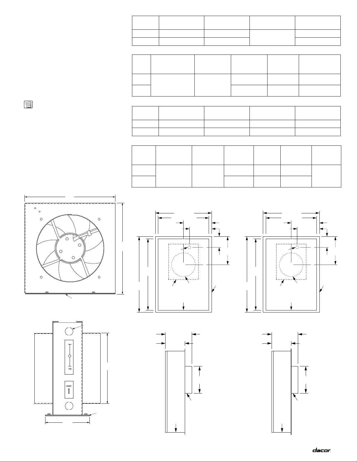
Model
No.
Overall Chassis
Width “A”
Overall Chassis
Height “B”
Overall Chassis
Length “C”
Duct Diameter
“D”
ILB8 10 5/8” (270mm) 10 1/2” (267mm)
5” (127mm)
8” (203mm)
ILB10 12 5/8” (321mm) 12 1/2” (318mm) 10” (254mm)
Model
No.
Electrical Supply
Requirements
Maximum
Duct Length
Total
Connected
Load
Blower
Rating*
Approximate
Shipping Weight
ILB8
Refer to Ventilator
Specifications
Max. 60
Equivalent
Straight Feet
0.1kW (1A) 500 CFM 15 lbs.
ILB10 0.2kW (2A) 900 CFM 18 lbs.
ILB Overall Dimensions
ILB Specifications
Model
No.
Overall Chassis
Width
Overall Chassis
Height
Overall Chassis
Length Duct Diameter
REMP3 19” (483mm) 5 13/16” (148mm) 25 1/2” (648mm) 8” (203mm)
REMP16 26” (660mm) 9 9/16” (243mm) 33 1/2” (851mm) 10” (254mm)
Model
No.
Electrical
Supply
Requirements
Maximum
Duct Length
Total
Connected
Load
Blower
Rating*
Approx.
Shipping
Weight Finish
REMP3 Refer to
Ventilator
Specifications
Max. 60
Equivalent
Straight Feet
0.5kW (4A) 620 CFM 35 lbs. Galvanized
(may be
painted)REMP16 0.3kW (3A) 980 CFM 55 lbs.
REMP Overall Dimensions
REMP Specifications
"A"
"B"
Attachment
Surface
ROTATION
AIRFLOW
120V, 60Hz, 15A POWER SUPPLY
CAUTION: DISCONNECT POWER SUPPLY AT THE FUSE BOX BEFORE SERVICING THIS EQUIPMENT
FAN MOTOR
GR
N
DACOR P/N 85829
WIRING DIAGRAM, ILB-8
M
BK
L
"C"
"D"
Attachment
Surface
Electrical
Access Panel
ILB Overall Dimensions
Front View
ILB Overall Dimensions
Side View
17 1/8" (435mm)
19" (483mm)
24 1/16"
(611mm)
3 5/8"
(92mm)
9 1/4"
(235mm)
Mounting
Flange
25 1/2"
(648mm)
7 1/2"
(191mm)
9 1/2" (241mm)
Discharge
Cutout
Location
Intake Collar
Power Supply
Conduit
Location
C
L
C
L
C
L
C
L
REMP3 Overall Dimensions
Top View
5 13/16"
(148mm)
8"
(203mm)
7 13/16"
(198mm)
Discharge
Intake Collar
REMP3 Overall Dimensions
Side View
24" (610mm)
26" (660mm)
31 1/2"
(800mm)
3 1/2"
(89mm)
12 1/4"
(311mm)
Mounting
Flange
33 1/2"
(851mm)
9 1/2"
(241mm)
12 11/16" (322mm)
Discharge
Cutout
Location
Intake Collar
Power Supply
Conduit
Location
C
L
C
L
C
L
C
L
REMP16 Overall Dimensions
Top View
9 9/16"
(243mm)
10"
(254mm)
11 1/2"
(292mm)
Discharge
Intake Collar
REMP16 Overall Dimensions
Side View
* All the CFM Blower Ratings are valued at 0” (zero-inch) static pressure.
Loading ...
Loading ...
Loading ...