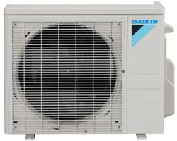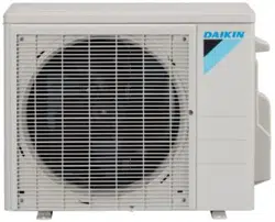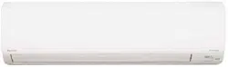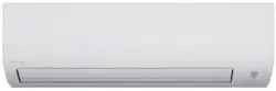
Enjoy year-round comfort.
Enjoy year-round comfort.
Enjoy year-round comfort.
Enjoy year-round comfort.
Enjoy year-round comfort.
DAIKIN ROOM AIR CONDITIONER
OPERATION MANUAL
MODELS
FTX09NMVJU
FTX12NMVJU
FTX15NMVJU
FTX18NMVJU
FTX24NMVJU
FTXN09NMVJU
FTXN12NMVJU
FTXN18NMVJU
FTXN24NMVJU
English
Français
Español
00_CV_3P379751-4C.indd 1 10/22/2015 11:54:38
1
Features
Enhanced comfort and energy
savings
ECONO
This function enables ef cient operation by limiting the maximum power
consumption. It is useful when using the air conditioner and other electrical
devices simultaneously on a shared electrical circuit.
Page 16
COMFORT AIRFLOW
The air ow direction is upward while in COOL operation, and downward while
in HEAT operation. This function prevents cold or warm air from blowing
directly on your body.
Page 15
01_EN_3P379751-4C.indd 1 11/6/2015 16:14:27
2
English
Contents
Read Before Operation
Safety Considerations ..................................... 3
Names of Parts
FTX09NMVJU / FTX12NMVJU / FTXN09NMVJU / FTXN12NMVJU ... 5
Names of Parts
FTX15NMVJU / FTX18NMVJU / FTX24NMVJU /
FTXN18NMVJU / FTXN24NMVJU ..................... 7
Preparation Before Operation ...................... 10
Basic Operation
AUTO · COOL · DRY · HEAT ·
FAN ONLY Operation .........................11
Adjusting the Airflow Rate ..................13
Adjusting the Airflow Direction ...........14
Useful Functions
COMFORT AIRFLOW Operation .......15
POWERFUL Operation ......................15
ECONO Operation .............................16
TIMER Operation
ON/OFF TIMER Operation ................17
Care
Care and Cleaning
FTX09NMVJU / FTX12NMVJU / FTXN09NMVJU / FTXN12NMVJU
... 19
Care and Cleaning
FTX15NMVJU / FTX18NMVJU / FTX24NMVJU /
FTXN18NMVJU / FTXN24NMVJU
.................... 22
Care and Cleaning
All models ......................................................... 25
When the Need Arises
FAQ .............................................................. 26
Troubleshooting ........................................... 27
01_EN_3P379751-4C.indd 2 11/6/2015 16:14:29

3
Read Before Operation
Safety Considerations
Read these Safety Considerations for Operations carefully
before operating an air conditioner or heat pump.
Make sure that the unit operates properly during the startup
operation. Instruct the user on how to operate and maintain
the unit.
Inform users that they should store this operation manual
with the installation manual for future reference.
Meanings of DANGER, WARNING, CAUTION, and NOTE
Symbols:
DANGER
...........
Indicates an imminently hazardous
situation which, if not avoided, will
result in death or serious injury.
WARNING
.........
Indicates a potentially hazardous
situation which, if not avoided,
could result in death or serious
injury.
CAUTION
..........
Indicates a potentially hazardous
situation which, if not avoided, may
result in minor or moderate injury.
It may also be used to alert against
unsafe practices.
NOTE
................
Indicates situations that may result
in equipment or property-damage
accidents only.
DANGER
• Do not install the unit in an area where ammable
materials are present due to risk of explosion resulting in
serious injury or death.
• Any abnormalities in the operation of the air conditioner
or heat pump, such as smoke or re, could result in
severe injury or death. Turn off the power and contact
your dealer immediately.
• Refrigerant gas may produce toxic gas if it comes into
contact with re, such as from a fan heater, stove, or
cooking device. Exposure to this gas could cause severe
injury or death.
• For refrigerant leakage, consult your dealer.
Refrigerant gas is heavier than air and replaces oxygen.
A massive leak could lead to oxygen depletion, especially
in basements, and an asphyxiation hazard could occur
leading to serious injury or death.
• If equipment utilizing a burner is used in the same room
as the air conditioner or heat pump, there is the danger
of oxygen deciency which could lead to an asphyxiation
hazard resulting in serious injury or death. Be sure to
ventilate the room sufciently to avoid this hazard.
• Safely dispose of the packing materials. Packing
materials, such as nails and other metal or wooden parts,
may cause stabs or other injuries.
• Tear apart and throw away plastic packaging bags so
that children will not play with them. Children playing with
plastic bags face the danger of death by suffocation.
WARNING
• Contact your dealer for repair and maintenance.
Improper repair and maintenance may result in water
leakage, electric shock, and re. Only use accessories
made by Daikin that are specically designed for use with
the equipment and have them installed by a professional.
• Contact your dealer to move and reinstall the air
conditioner or heat pump. Incomplete installation may
result in water leakage, electric shock, and re.
• Never let the indoor unit or the remote controller get wet.
Water can cause an electric shock or a re.
• Never use ammable spray such as hair spray, lacquer,
or paint near the unit. Flammable spray may cause a re.
• When a fuse blows out, never replace it with one of
incorrect ampere ratings or different wires. Always replace
any blown fuse with a fuse of the same specication.
• Never remove the fan guard of the unit. A fan rotating at
high speed without the fan guard is very dangerous.
• Never inspect or service the unit by yourself. Contact a
qualied service person to perform this work.
• Tu r n off all electrical power before doing any maintenance
to avoid the risk of serious electric shock; never sprinkle
or spill water or liquids on the unit.
• Do not touch the switch with wet ngers. Touching a
switch with wet ngers can cause electric shock.
• Do not allow children to play on or around the unit to
prevent injury.
•
The heat exchanger ns are sharp enough to cut. To avoid
injury wear gloves or cover the ns while working around them.
•
Do not put a nger or other objects into the air inlet or air
outlet. The fan is rotating at high speed and will cause injury.
• Check the unit foundation for damage on a continuous
basis, especially if it has been in use for a long time. If left
in a damaged condition the unit may fall and cause injury.
• Placing a ower vase or other containers with water or
other liquids on the unit could cause a shock or re if a
spill occurs.
• Do not touch the air outlet or horizontal blades while
the swing ap is in operation because ngers could get
caught and injured.
• Never touch the internal parts of the controller. Do not
remove the front panel because some parts inside are
dangerous to touch. To check and adjust internal parts,
contact your dealer.
CAUTION
• Do not use the air conditioner or heat pump for any other
purposes other than comfort cooling or heating.
Do not use the unit for cooling precision instruments,
food, plants, animals or works of art.
01_EN_3P379751-4C.indd 3 11/6/2015 16:14:29
4
English
Read Before Operation
• Do not place items under the indoor unit as they may be
damaged by condensates that may form if the humidity is
above 80% or if the drain outlet gets blocked.
• Before cleaning, stop the operation of the unit by turning
the power off or by pulling the supply cord out from its
receptacle. Otherwise, an electric shock and injury may
result.
• Do not wash the air conditioner or heat pump with
excessive water. An electric shock or re may result.
• Avoid placing the controller in a spot splashed with water.
Water entering the controller may cause an electric shock
or damage the internal electronic parts.
• Do not operate the air conditioner or heat pump when
using a room-fumigation type of insecticide.
Failure to observe this could cause the chemicals to be
deposited in the unit and can endanger the health of
those who are hypersensitive to chemicals.
• Do not turn off the power immediately after stopping
operation. Always wait for at least 5 minutes before
turning off the power. Otherwise, water leakage may
occur.
• The appliance is not intended for use by young children
or inrm persons without supervision.
• The remote controller should be kept away from children
so they cannot play with it.
• Consult with the installation contractor for cleaning.
• Incorrect cleaning of the inside of the air conditioner
or heat pump could make the plastics parts break and
cause water leakage or electric shock.
•
Do not touch the air inlet or aluminum n of the air
conditioner or heat pump as they can cut and cause injury.
•
Do not place objects in direct proximity of the outdoor unit.
Do not let leaves and other debris accumulate around
the unit. Leaves are a hotbed for small animals which can
enter the unit. Once inside the unit, animals can cause
the unit to malfunction, and cause smoke or re when
they make contact with electrical parts.
NOTE
• Never press the button of the remote controller with
a hard, pointed object. The remote controller may be
damaged.
• Never pull or twist the electric wire of the remote
controller. It may cause the unit to malfunction.
• Do not place appliances that produce open ames in
places that are exposed to the airow of the unit or under
the indoor unit. It may cause incomplete combustion or
deformation of the unit due to the heat.
• Do not expose the controller to direct sunlight. The LCD
display can become discolored and may fail to display the
data.
• Do not wipe the controller operation panel with benzene,
thinner, chemical dust cloth, etc. The panel may get
discolored or the coating can peel off. If it is heavily dirty,
soak a cloth in water-diluted neutral detergent, squeeze it
well and wipe the panel clean. Then wipe it with another
dry cloth.
• Dismantling of the unit, disposal of the refrigerant, oil, and
additional parts, should be done in accordance with the
relevant local, state, and national regulations.
• Operate the air conditioner or heat pump in a sufciently
ventilated area and not surrounded by obstacles. Do
not use the air conditioner or heat pump in the following
places.
a. Places with a mist of mineral oil, such as cutting oil.
b. Locations such as coastal areas where there is a lot
of salt in the air.
c. Locations such as hot springs where there is a lot of
sulfur in the air.
d. Locations such as factories where the power voltage
varies a lot.
e. In cars, boats, and other vehicles.
f. Locations such as kitchens where oil may splatter or
where there is steam in the air.
g. Locations where equipment produces
electromagnetic waves.
h. Places with an acid or alkaline mist.
i. Places where fallen leaves can accumulate or where
weeds can grow.
• Ta ke snow protection measures. Contact your dealer for
the details of snow protection measures, such as the use
of a snow protection hood.
• Do not attempt to do electrical work or grounding work
unless you are licensed to do so. Consult with your dealer
for electrical work and grounding work.
• Pay attention to operating sound. Be sure to use the
following places:
a. Places that can sufciently withstand the weight of
the air conditioner or heat pump yet can suppress the
operating sound and vibration.
b.
Places where warm air from the air outlet of the
outdoor unit or the operating sound of the outdoor unit
does not annoy neighbors.
• Make sure that there are no obstacles close to the
outdoor unit. Obstacles close to the outdoor unit may
drop the performance of the outdoor unit or increase the
operating sound of the outdoor unit.
• Consult your dealer if the air conditioner or heat pump in
operation generates unusual noise.
• Make sure that the drainpipe is installed properly to drain
water. If no water is discharged from the drainpipe while
the air conditioner or heat pump is in the cooling mode,
the drainpipe may be clogged with dust or dirt and water
leakage from the indoor unit may occur. Stop operating
the air conditioner or heat pump and contact your dealer.
01_EN_3P379751-4C.indd 4 11/6/2015 16:14:29
ON/OFF
5
Read Before Operation
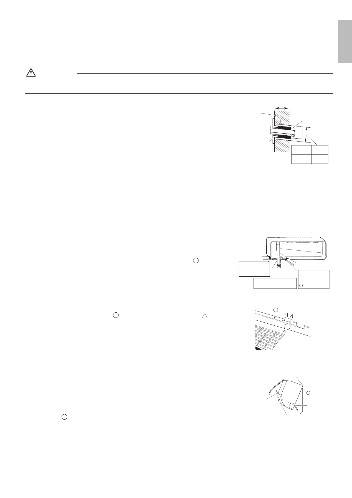
Indoor Unit
Display
Air inlet
Front panel
Air outlet
Louvers (vertical blades)
• The louvers are inside of the air
outlet.
Page 14
Flap (horizontal blade)
Page 14
Model name Indoor temperature
sensor
• Detects the air temperature
around the unit.
OPERATION lamp (green)
TIMER lamp (orange)
Page 17,18
Signal receiver
• Receives signals from the remote
controller.
• When the unit receives a signal, you
will hear a beep sound.
Case Sound type
Operation start beep-beep
Setting changed beep
Operation stop long beep
Indoor unit ON/OFF switch
• Press this switch once to start operation.
Press once again to stop it.
• For the operation mode setting, refer to the following table.
Mode Temperature setting Airow rate
AUTO 77°F (25°C) AUTO
• This switch can be used when the remote controller is missing.
Names of Parts
FTX09NMVJU / FTX12NMVJU / FTXN09NMVJU / FTXN12NMVJU
01_EN_3P379751-4C.indd 5 11/6/2015 16:14:30
6
English
Read Before Operation
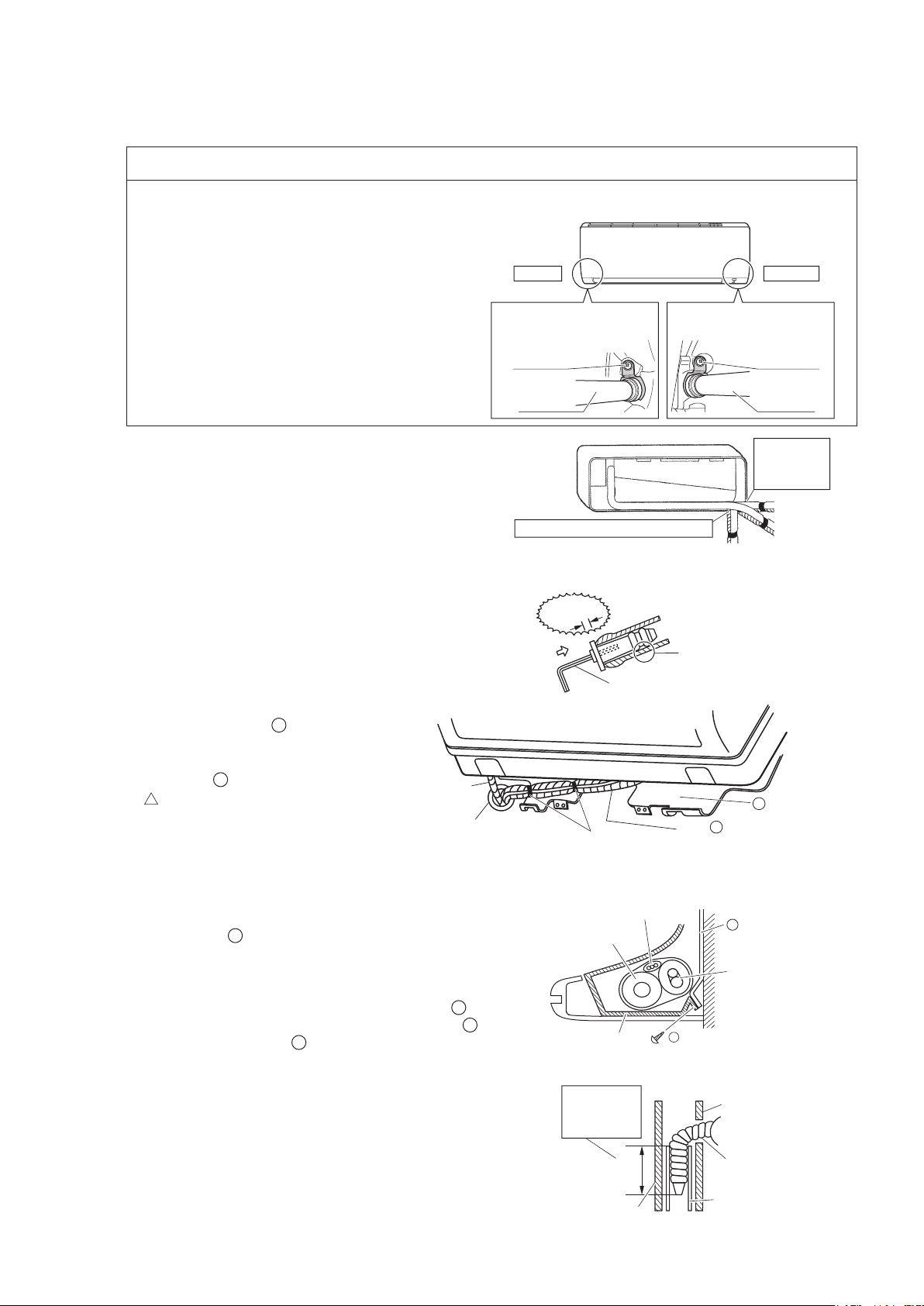
Outdoor Unit
• The appearance of the outdoor unit may differ between different models.
Open the front panel
Air lter
Refrigerant pipes and
inter-unit wire
Ground terminal (inside)
Drain hose
Air outlet
Model name
Air inlet
(back and side)
Outdoor temperature
sensor (back)
Titanium apatite
photocatalytic air-purifying
lter (without frame)*
*FTXN09/12NMVJU: Sold separately.
01_EN_3P379751-4C.indd 6 11/6/2015 16:14:30
7
Read Before Operation
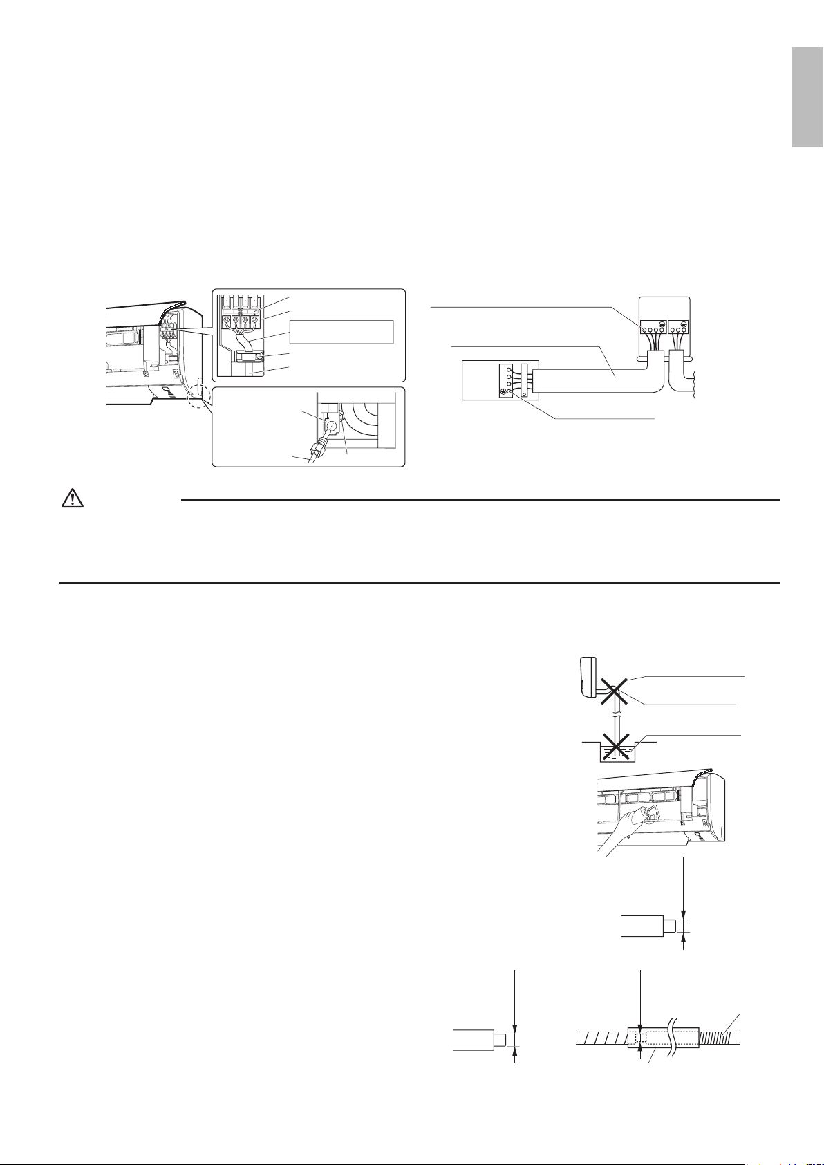
Air inlet
ON/OFF
Indoor Unit
Display
Front panel
Air outlet
Louvers (vertical blades)
• The louvers are inside of the air
outlet.
Page 14
Flaps (horizontal blades)
Page 14
Model name
Indoor temperature sensor
• Detects the air temperature around
the unit.
OPERATION lamp (green)
TIMER lamp (orange)
Page 17,18
Signal receiver
• Receives signals from the remote
controller.
• When the unit receives a signal, you
will hear a beep sound.
Case Sound type
Operation start beep-beep
Setting changed beep
Operation stop long beep
Indoor unit ON/OFF switch
• Press this switch once to start operation.
Press once again to stop it.
• For the operation mode setting, refer to the following table.
Mode Temperature setting Airow rate
AUTO 77°F (25°C) AUTO
• This switch can be used when the remote controller is missing.
Names of Parts
FTX15NMVJU / FTX18NMVJU / FTX24NMVJU / FTXN18NMVJU / FTXN24NMVJU
01_EN_3P379751-4C.indd 7 11/6/2015 16:14:30
8
EnglishEnglish
Read Before Operation
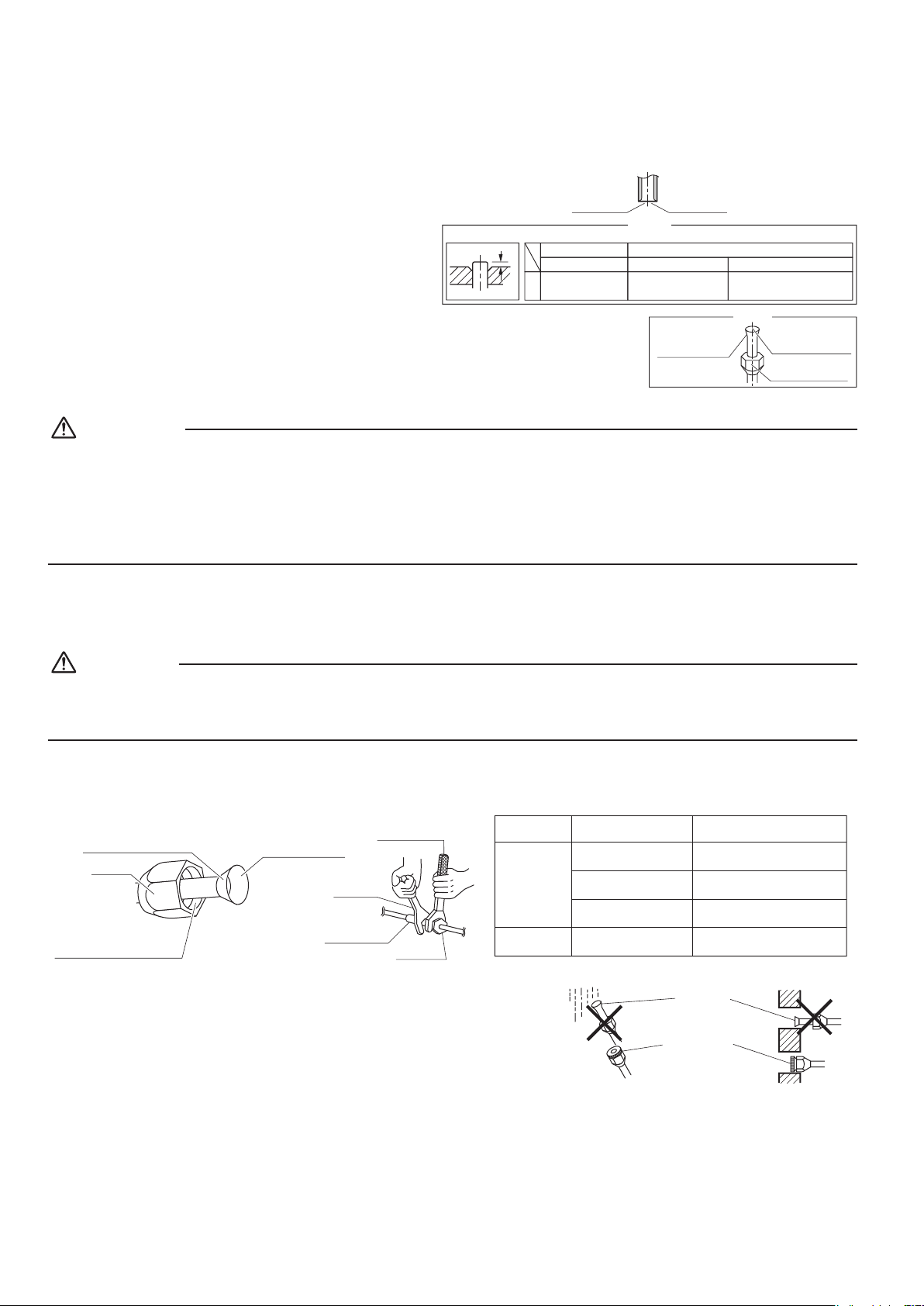
Outdoor Unit
• The appearance of the outdoor unit may differ between different models.
Open the front panel
Refrigerant pipes and
inter-unit wire
Drain hose
Air outlet
Model name
Ground terminal (inside)
Air inlet
(back and side)
Outdoor temperature
sensor (back)
Titanium apatite
photocatalytic air-purifying
lter (with frame)*
*FTXN18/24NMVJU: Sold separately.
Air lter
01_EN_3P379751-4C.indd 8 11/6/2015 16:14:31
9
Read Before Operation
Names of Parts
Remote Controller
Display (LCD)
• Displays the current settings.
(In this illustration, each section is
shown with its displays on for the
purpose of explanation.)
AUTO button
• Automatically selects an appropriate
operation mode (COOL or HEAT)
based on the indoor temperature and
starts the operation.
Page 11
Direct operation buttons
• Starts the COOL, DRY, HEAT or FAN
ONLY operation.
Page 11
TEMPERATURE
adjustment button
• Changes the temperature setting.
Page 12
COMFORT button
• COMFORT AIRFLOW operation.
Page 15
POWERFUL button
• POWERFUL operation.
Page 15
OFF TIMER button
(NIGHT SET mode)
Page 18
ON TIMER button
Page 17
Signal transmitter
Receiver
•
To use the remote controller, aim the
transmitter at the indoor unit. If there is
anything blocking the signals between
the unit and the remote controller, such
as a curtain, the unit may not operate.
• The maximum transmission distance
is about 23ft (7m).
OFF button
• Stops the operation.
Page 12
FAN setting button
• Selects the air ow rate setting.
Page 13
ECONO button
• ECONO operation.
Page 16
SWING button
•
Adjusts the air ow direction
.
Page 14
TIMER CANCEL button
• Cancels the timer setting.
Page 17,18
Unit Remote Controller
FTX09/12/15/18/24NMVJU
ARC480A8 with backlight
FTXN09/12/18/24NMVJU ARC480A6 without backlight
01_EN_3P379751-4C.indd 9 11/6/2015 16:14:34
10
EnglishEnglish
Read Before Operation
Preparation Before Operation
To insert the batteries
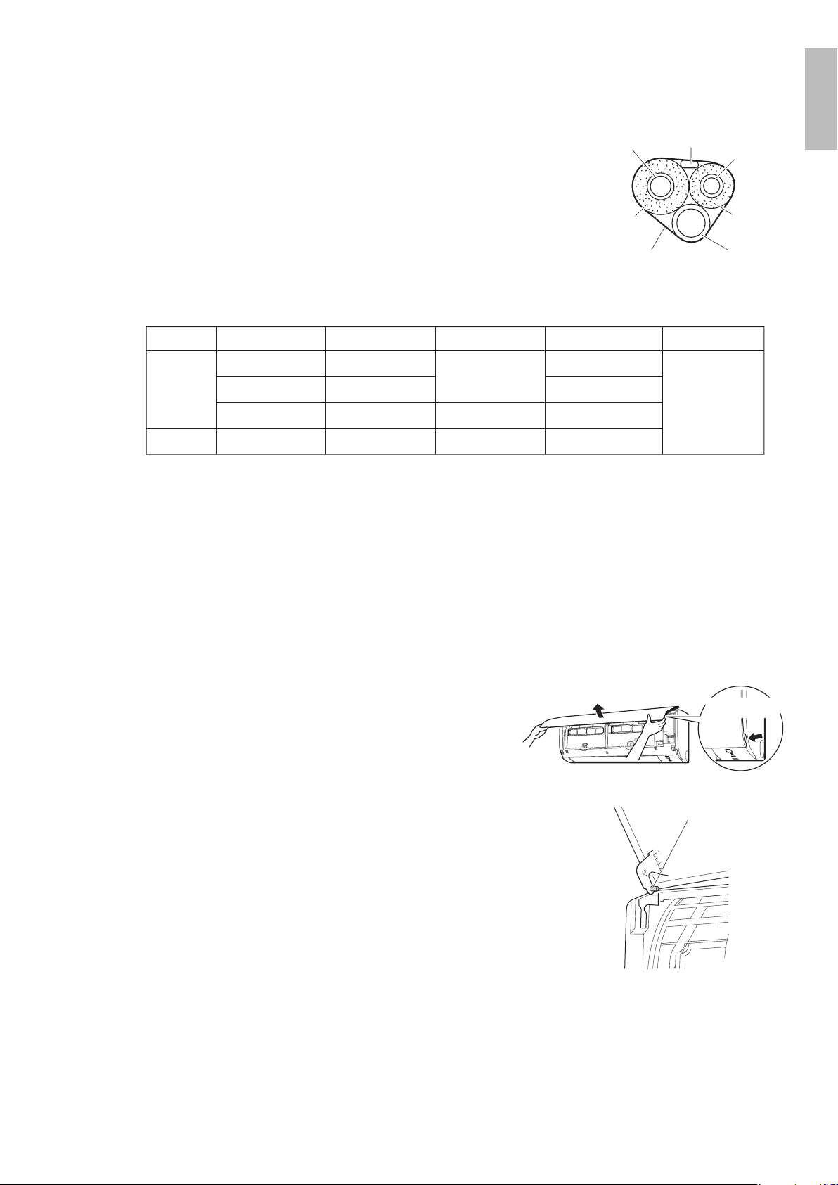
1. Remove the back cover by sliding and then
slightly lifting it.
2. Insert 2 dry batteries AAA.LR03 (alkaline).
3. Replace the back cover.
To x the remote controller holder to a wall
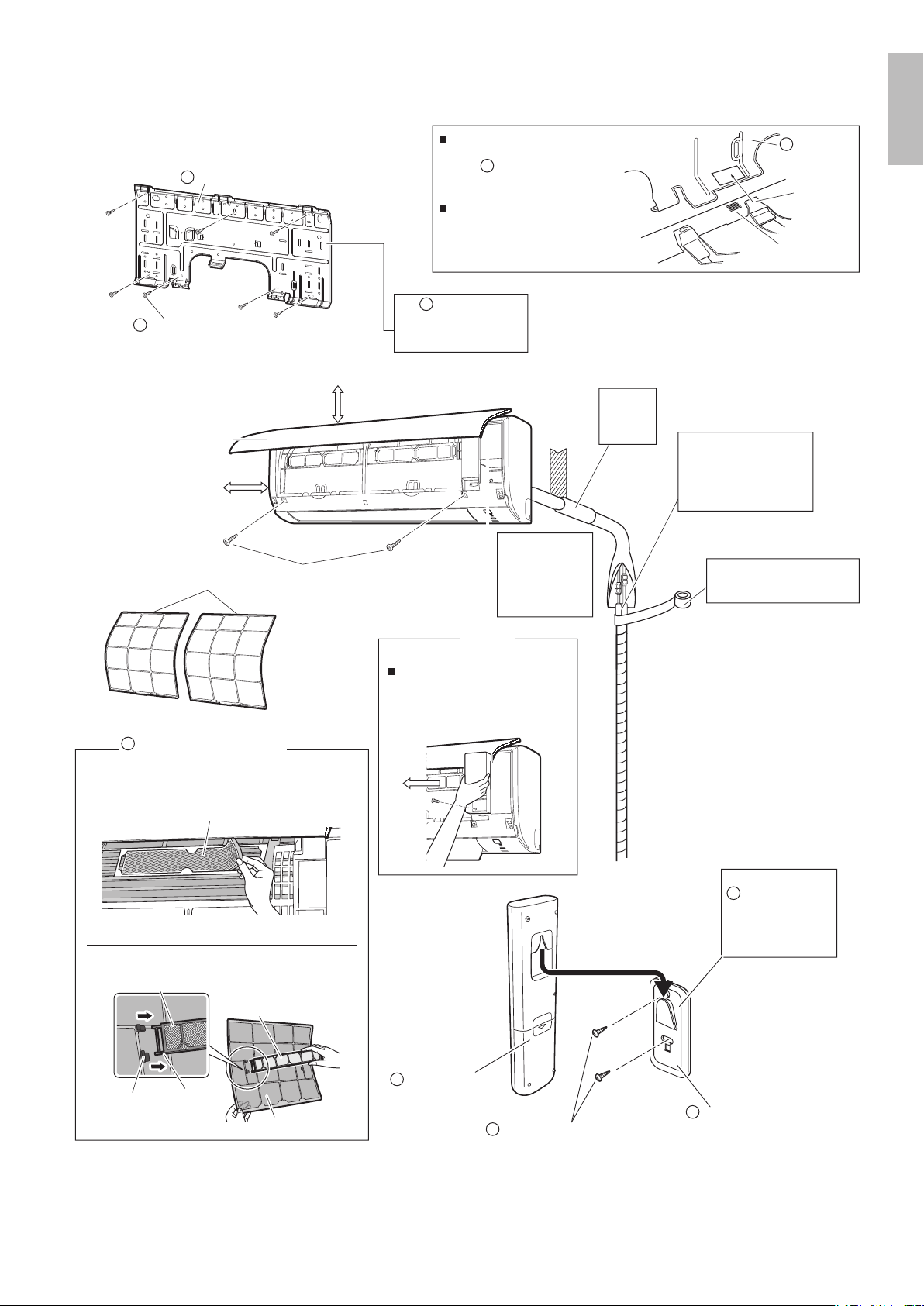
1.
Choose a place where the signals reach the unit.
2.
Attach the holder to a wall, a pillar, or similar
location with the screws supplied with the holder.
3. Hang the remote controller on the remote
controller holder.
Fahrenheit/Celsius display switch
Press and (TIMER button)
simultaneously for about 5 seconds.
• The temperature will be displayed in Celsius when it is presently displayed in
Fahrenheit, and vice versa.
• The switch operation is only possible when the temperature is being displayed.
Turn on the circuit breaker
• After the power is turned on, the ap of the indoor unit opens and closes once to set the
reference position.
Position and
correctly!
2
3
1
Remote
controller holder
Remote controller
Screws
NOTE
Notes on batteries
• When replacing the batteries, use batteries of the same type, and replace bothold batteries together.
• The batteries will last for about 1 year. However, if the remote controller display begins to fade and the possible transmission range becomes
shorter within a year, replace both batteries with new, size AAA.LR03 (alkaline) batteries.
• The batteries supplied with the remote controller are for initial operation. The batteries may run out in less than 1 year.
Note on remote controller
• Do not drop the remote controller. Do not get it wet.
Fahrenheit/Celsius display change function of remote controller
• The set temperature may increase when the display is changed to Celsius from Fahrenheit, because a fraction of 0.5°C is rounded up.
•
Example: A set temperature of 65°F (equivalent to 18.5°C) will be converted into 19°C.
When the display is changed to Fahrenheit again, the set temperature will be converted into 66°F (equivalent to 19°C) instead of the original
set temperature (65°F) but a set temperature of 66°F (equivalent to 19°C) will be converted into 19°C with no temperature change.
•
A reception sound will go off for the transmission of set temperature to the indoor unit at the time of setting the Fahrenheit/Celsius display change function.
01_EN_3P379751-4C.indd 10 11/6/2015 16:14:35
11
Basic Operation
AUTO · COOL · DRY · HEAT · FAN ONLY
Operation
NOTE
Notes on AUTO operation
• In AUTO operation, the system selects an appropriate operation mode (COOL or HEAT) based on the indoor temperature and starts the
operation.
• The system automatically reselects setting at a regular interval to bring the indoor temperature to the user-setting level.
Note on DRY operation
• Eliminates humidity while maintaining the indoor temperature as much as possible. It automatically controls temperature and airow rate, so
manual adjustment of these functions is unavailable.
The air conditioner operates with the operation mode of your choice.
To start operation
AUTO operation
• To automatically select an appropriate temperature and operation mode.
Press .
COOL operation
• To lower the temperature.
Press .
DRY operation
• To lower the humidity.
Press .
HEAT operation
• To raise the temperature.
Press .
FAN ONLY operation
• To circulate air in the room.
Press .
• The OPERATION lamp lights green.
Display
01_EN_3P379751-4C.indd 11 11/6/2015 16:14:36
12
English
Basic Operation
To stop operation
Press .
• The OPERATION lamp goes off.
To change the temperature setting
Press .
• Press to raise the temperature and press to lower the temperature.
COOL operation HEAT operation AUTO operation DRY or FAN ONLY operation
64-90°F
(18-32°C)
50-86°F
(10-30°C)
64-86°F
(18-30°C)
The temperature setting
cannot be changed.
Tips for saving energy
Keeping the temperature setting at a moderate level helps save energy.
• Recommended temperature setting
− For cooling: 78-82°F (26-28°C)
− For heating: 68-75°F (20-24°C)
Cover windows with a blind or a curtain.
• Blocking sunlight and air from outdoors increases the cooling (heating) effect.
Keep the air lters clean.
• Clogged air lters cause inef cient operation and waste energy. Clean them once every 2weeks.
Page 20, 23
If you are not going to use the air conditioner for a long period, for example in spring or autumn, turn off the circuit
breaker.
• The air conditioner always consumes a small amount of electricity even while it is not operating.
01_EN_3P379751-4C.indd 12 11/6/2015 16:14:37
13
Basic Operation
You can adjust the air ow rate to increase your comfort.
To adjust the air ow rate setting
Press .
• Each pressing of changes the air ow rate setting in sequence.
AUTO Indoor unit quiet
Airflow rate 1-5 (Low to High)
• When the air ow is set to “ ”, quiet operation starts and noise from the indoor unit will
become quieter.
• In the quiet operation mode, the air ow rate is set to a weak level.
AUTO, COOL, HEAT and FAN ONLY operation DRY operation
The air ow rate setting
cannot be changed.
NOTE
Note on air ow rate setting
• At smaller air ow rates, the cooling (heating) effect is also smaller.
Adjusting the Air ow Rate
01_EN_3P379751-4C.indd 13 11/6/2015 16:14:37
14
English
Basic Operation
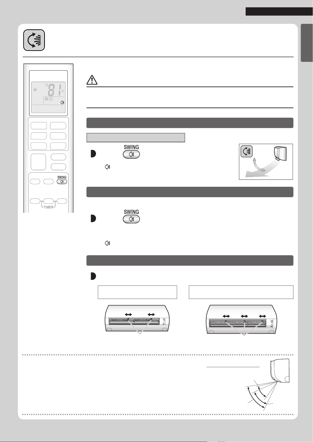
Adjusting the Airow Direction
You can adjust the airow direction to increase your comfort.
CAUTION
• Always use a remote controller to adjust the angles of the ap. Moving the ap forcibly by hand may cause a
malfunction.
• Be careful when adjusting the louvers. Inside the air outlet, a fan is rotating at a high speed.
To start auto swing
Up and down airow direction
Press .
• “ ” is displayed on the LCD.
• The ap (horizontal blade) will begin to swing.
To set the ap at the desired position
• This function is effective while the ap is in auto swing mode.
Press when the ap reaches the desired
position.
• “ ” disappears from the LCD.
To adjust the louvers at desired position
Hold the knobs and move the louvers (vertical blades).
FTX09NMVJU / FTX12NMVJU
FTXN09NMVJU / FTXN12NMVJU
FTX15NMVJU / FTX18NMVJU / FTX24NMVJU
FTXN18NMVJU / FTXN24NMVJU
Knobs
Knobs
Knobs
Knobs
NOTE
Notes on airow direction setting
• The movable range of the ap varies according to the operation mode.
• The ap will stop at the upper position when the airow rate is changed to low during the
up and down swing setting.
Movable range of the flap
COOL / DRY
HEAT
FAN ONLY
01_EN_3P379751-4C.indd 14 11/6/2015 16:14:38
Useful Functions
15
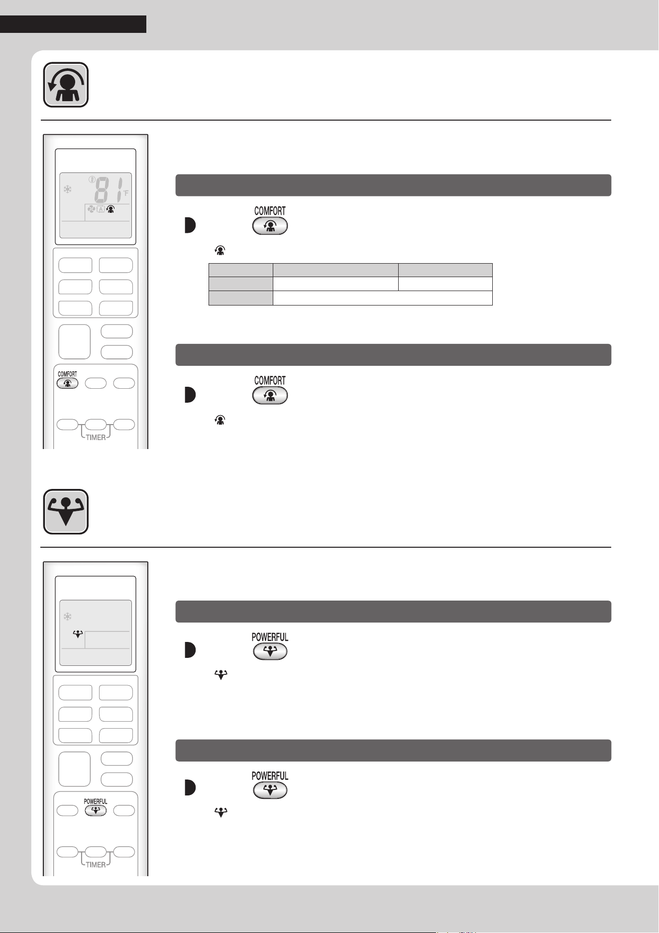
COMFORT AIRFLOW Operation
POWERFUL Operation
POWERFUL operation quickly maximizes the cooling (heating) effect in any
operation mode. In this mode, the air conditioner operates at maximum capacity.
To start POWERFUL operation
Press .
• “ ” is displayed on the LCD.
• POWERFUL operation ends in 20minutes. Then the system automatically operates again
with the previous settings which were used before POWERFUL operation.
To cancel POWERFUL operation
Press again.
• “ ” disappears from the LCD.
The air direction and ow rate are adjusted so that the air will not blow directly at
people in the room.
To start COMFORT AIRFLOW operation
Press .
• “ ” is displayed on the LCD.
COOL and DRY operation HEAT operation
Flap direction
Goes up Goes down
Airow rate
AUTO
• Not available in FAN ONLY mode.
To cancel COMFORT AIRFLOW operation
Press again.
• “ ” disappears from the LCD.
• The ap will return to the memory position from before COMFORT AIRFLOW operation.
01_EN_3P379751-4C.indd 15 11/6/2015 16:14:39
Useful Functions
16
English
NOTE
Note on COMFORT AIRFLOW operation
• If the up and down airow direction is selected, the COMFORT AIRFLOW operation will be canceled.
Notes on POWERFUL operation
• Pressing causes the settings to be canceled, and “ ” disappears from the LCD.
• POWERFUL operation will not increase the capacity of the air conditioner if the air conditioner is already in operation with its maximum capacity
demonstrated.
− In COOL, HEAT and AUTO operation
To maximize the cooling (heating) effect, the capacity of outdoor unit increases and the airow rate becomes xed at the maximum setting.
The temperature setting cannot be changed.
− In DRY operation
The temperature setting is lowered by 4.5°F (2.5°C) and the airow rate is slightly increased.
− In FAN ONLY operation
The airow rate is xed at the maximum setting.
Notes on ECONO operation
• Pressing causes the settings to be canceled, and “ ” disappears from the LCD.
• If the power consumption level is already low, switching to ECONO operation will not reduce the power consumption.
Some useful functions can be used together.
COMFORT AIRFLOW + ECONO Available
*Priority is given to the function of whichever button is pressed last.
POWERFUL + COMFORT AIRFLOW Not available*
POWERFUL + ECONO Not available*
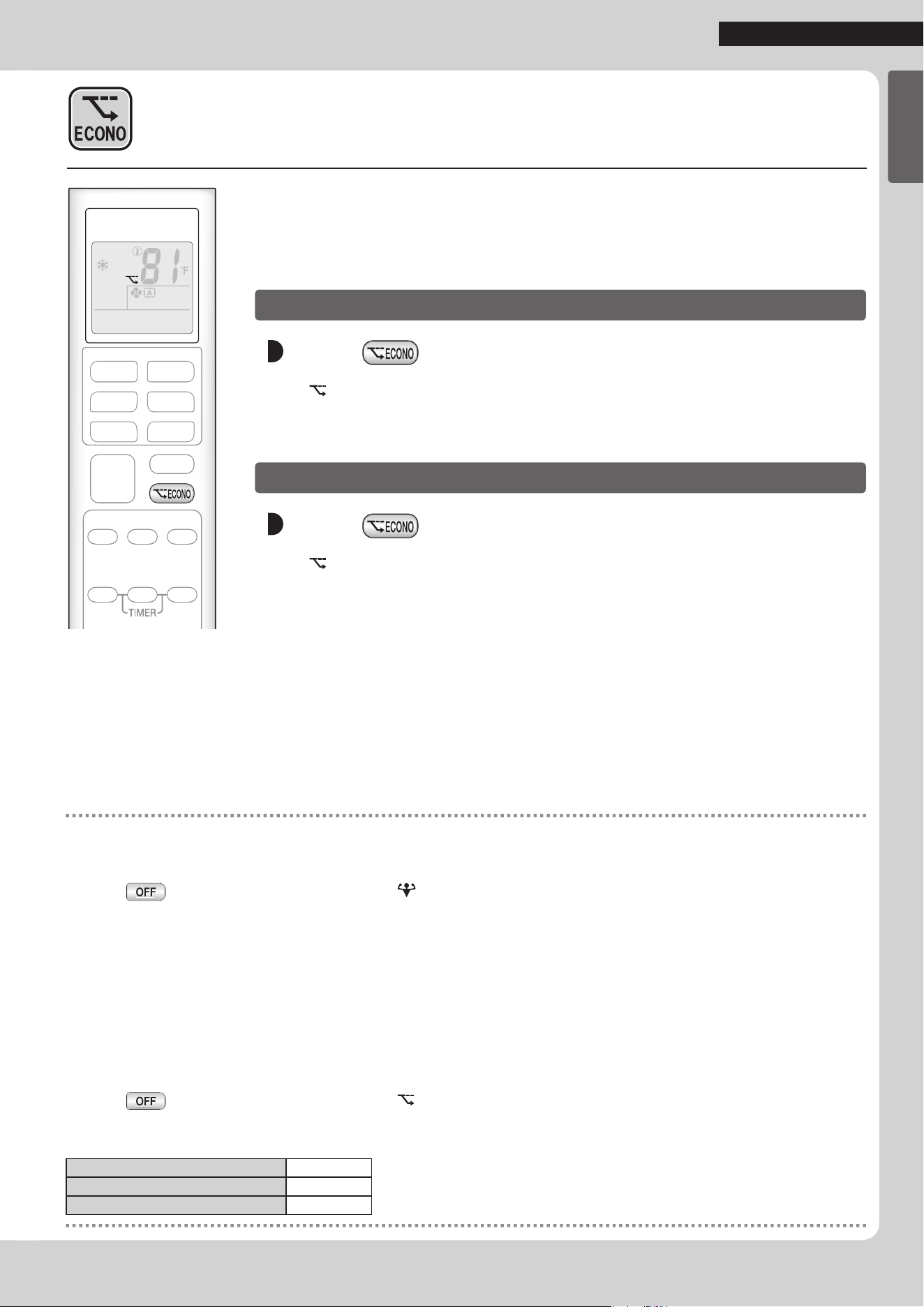
ECONO Operation
ECONO operation enables efcient operation by limiting the maximum power
consumption.
This function is useful to prevent the circuit breaker from tripping when the unit
operates alongside other appliances on the same circuit.
To start ECONO operation
Press .
• “ ” is displayed on the LCD.
• Not available in FAN ONLY mode.
To cancel ECONO operation
Press again.
• “ ” disappears from the LCD.
01_EN_3P379751-4C.indd 16 11/6/2015 16:14:39
17
TIMER Operation
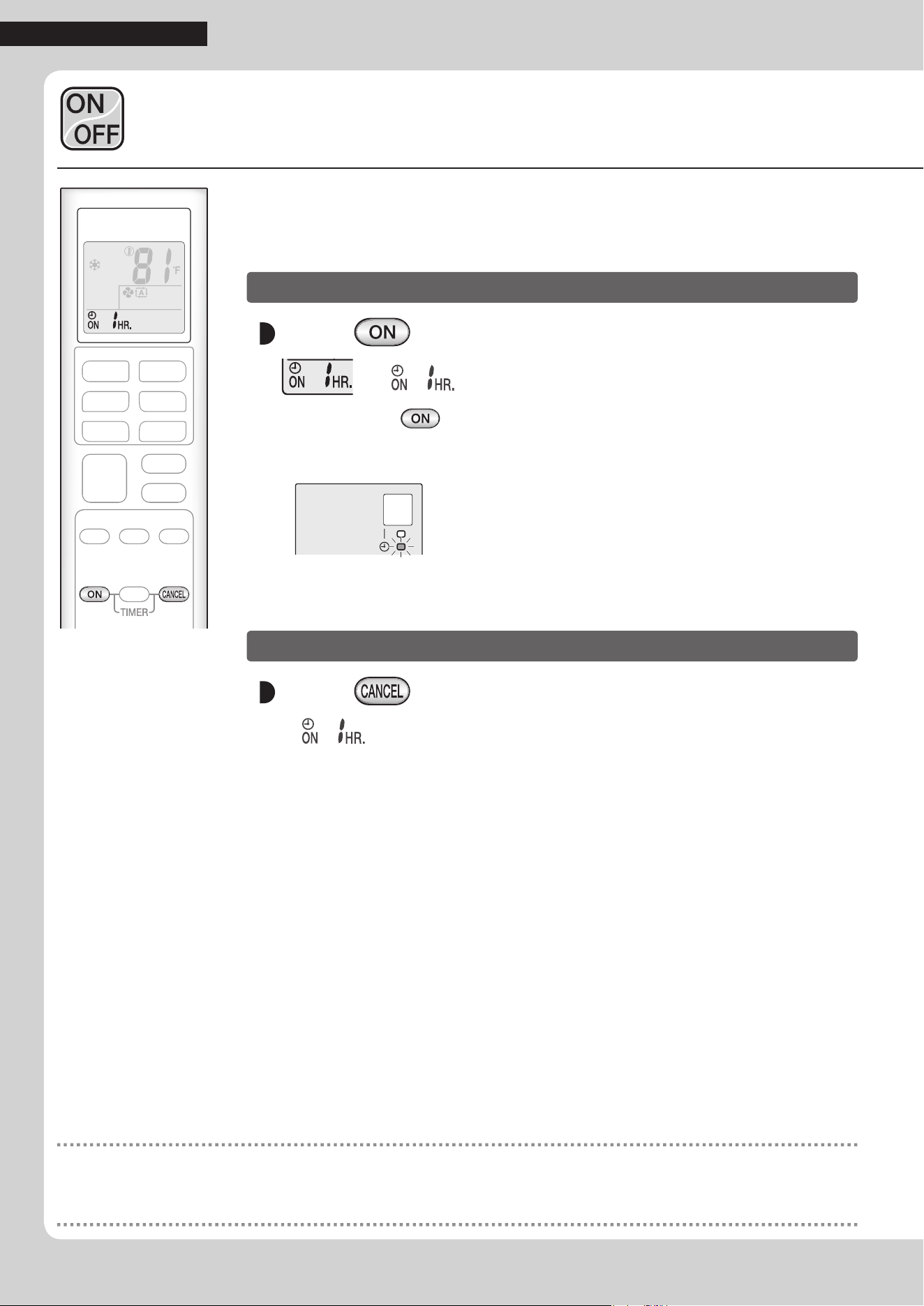
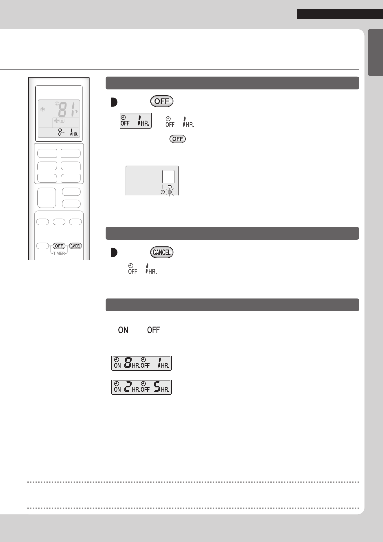
ON/OFF TIMER Operation
Timer functions are useful for automatically switching the air conditioner on or off
at night or in the morning. You can also use the ON TIMER and OFF TIMER
together.
To use ON TIMER operation
Press .
“ ” is displayed on the LCD.
• Each pressing of
changes the time setting by 1 hour.
The time can be set between 1 and 12 hours.
• The TIMER lamp lights orange.
Display
To cancel ON TIMER operation
Press .
• “ ” disappears from the LCD.
• The TIMER lamp goes off.
NOTE
In the following cases, set the timer again.
• After the circuit breaker has turned off.
• After a power failure.
• After replacing the batteries in the remote controller.
01_EN_3P379751-4C.indd 17 11/6/2015 16:14:40
18
English
TIMER Operation
To use OFF TIMER operation
Press .
“ ” is displayed on the LCD.
• Each pressing of
changes the time setting by 1 hour.
The time can be set between 1 and 12 hours.
• The TIMER lamp lights orange.
Display
To cancel OFF TIMER operation
Press .
• “ ” disappears from the LCD.
• The TIMER lamp goes off.
To combine ON TIMER and OFF TIMER operation
• A sample setting for combining the 2timers is shown below.
• “
” and “ ” are displayed on the LCD.
[Example]
When setting while the unit is operating
• Stops the unit 1 hour later and starts it 7 hours after that.
When setting while the unit is stopped
• Starts the unit 2 hours later and stops it 3 hours after that.
NOTE
NIGHT SET mode
• When the OFF TIMER is set, the air conditioner automatically adjusts the temperature setting (0.9°F (0.5°C) up in COOL, 3.6°F (2.0°C) down in
HEAT) to prevent excessive cooling (heating) during sleeping hours.
01_EN_3P379751-4C.indd 18 11/6/2015 16:14:41
19
Care
CAUTION
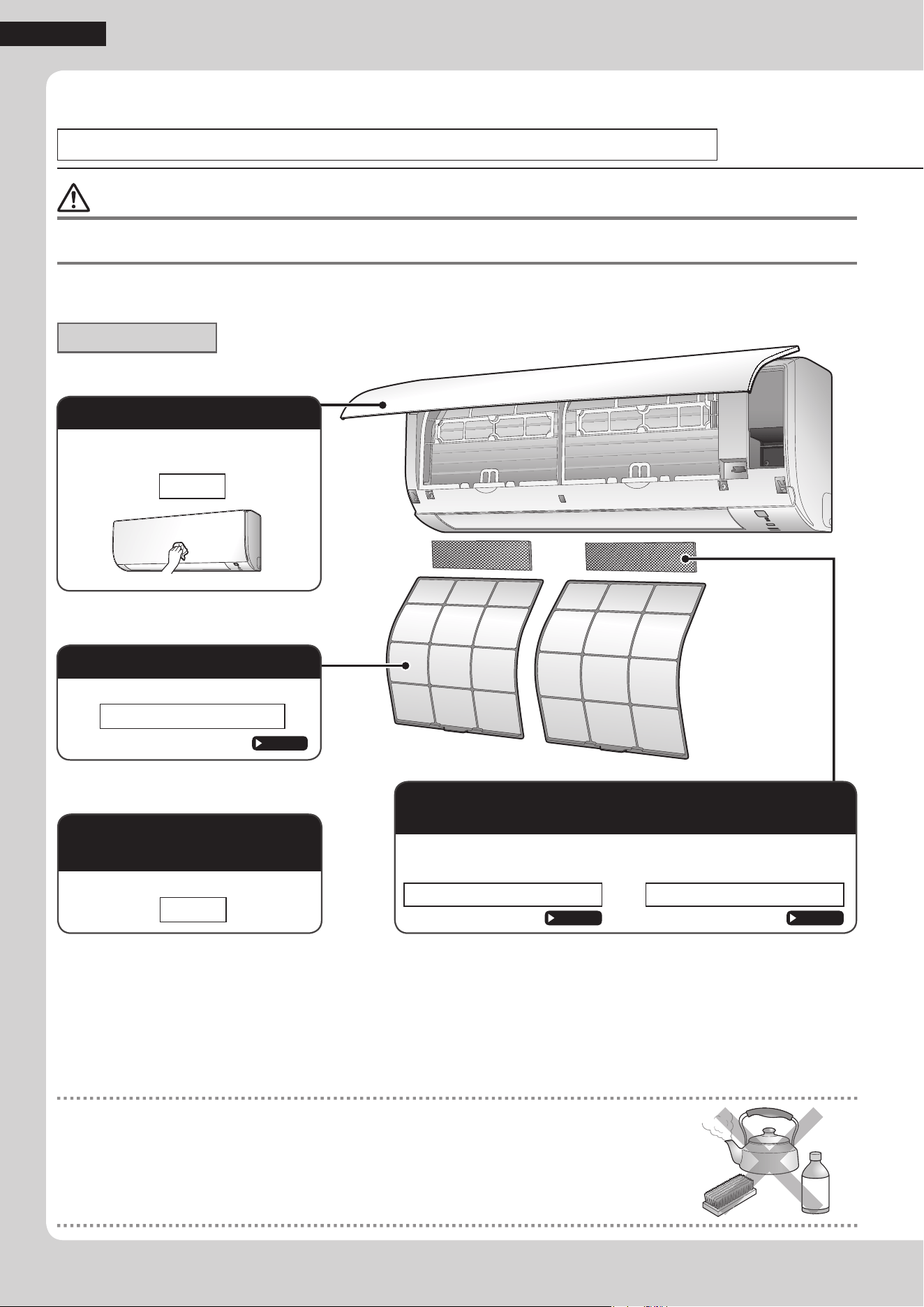
• Before cleaning, be sure to stop the operation and turn off the circuit breaker.
• Do not touch the aluminium ns of the indoor unit. If you touch those parts, this may cause an injury.
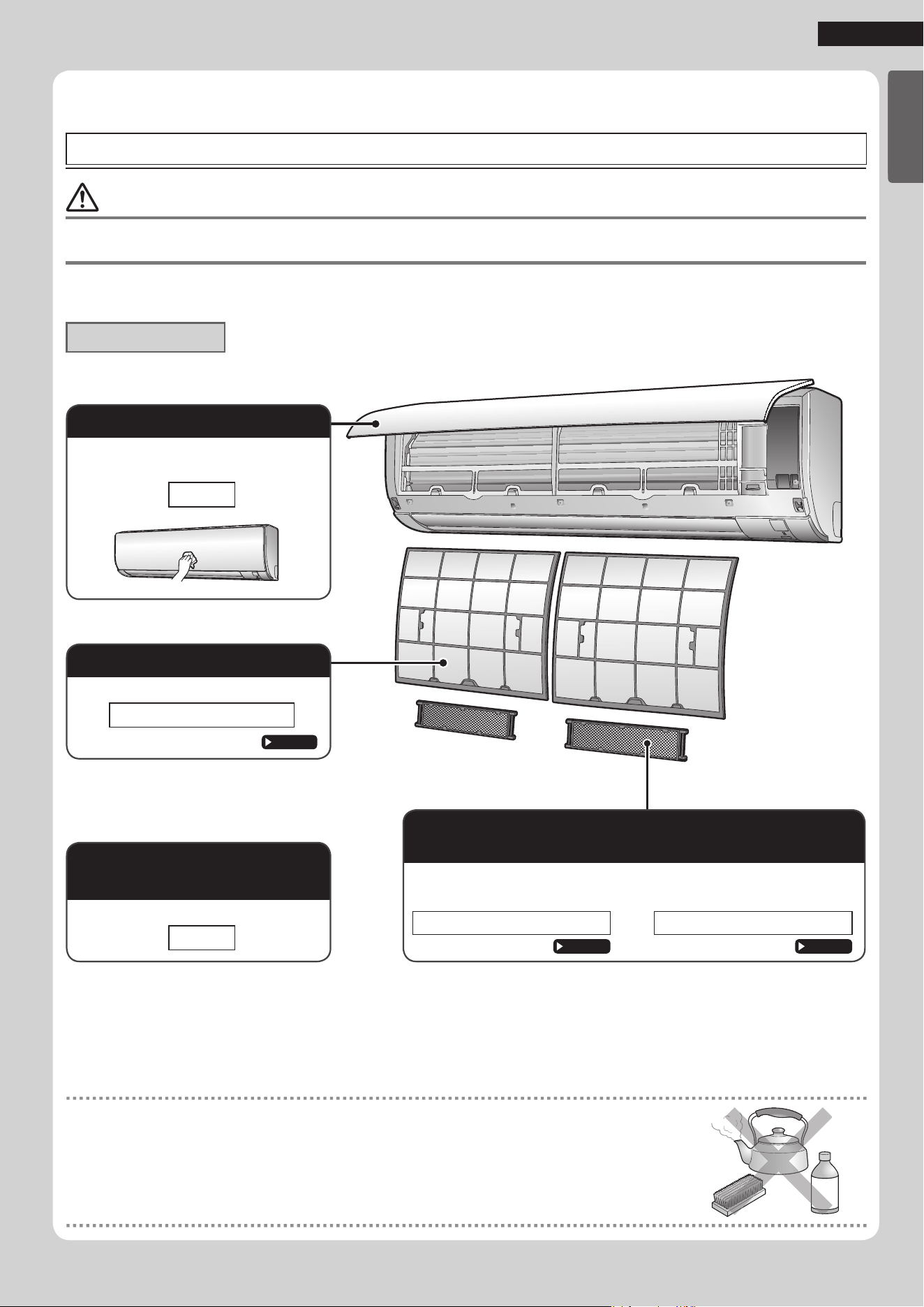
Quick reference
Cleaning parts
NOTE
For cleaning, do not use any of the following:
• Water hotter than 104°F (40°C)
• Volatile liquid such as benzene, petrol and thinner
• Polishing compounds
• Rough materials such as a scrubbing brush
Front panel
• Wipe it with a soft damp cloth.
• Only neutral detergent may be used.
If dirty
Indoor unit, outdoor unit
and remote controller
• Wipe them with a soft cloth.
If dirty
Care and Cleaning
FTX09NMVJU / FTX12NMVJU / FTXN09NMVJU / FTXN12NMVJU
*FTXN09/12NMVJU: Sold separately.
Air lter
• Vacuum dust or wash the lter.
Once every 2 weeks
Page 20
Titanium apatite photocatalytic air-purifying lter
(without frame)*
• Vacuum dust or replace the lter.
[Cleaning] [Replacement]
Once every 6 months Once every 3 years
Page 21
Page 21
01_EN_3P379751-4C.indd 19 11/6/2015 16:14:41
20
EnglishEnglish
Care
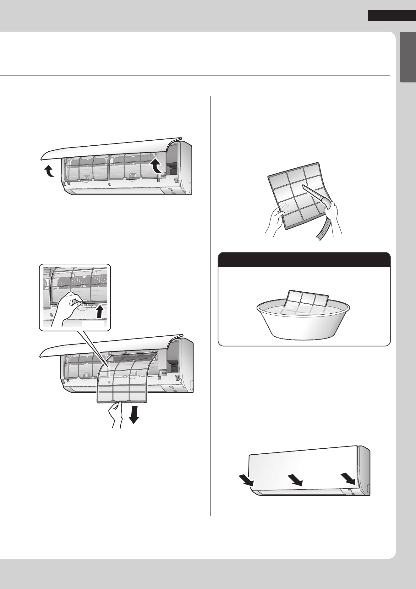
Air lter
1. Open the front panel.
• Hold the front panel by the sides and open it.
2. Pull out the air lters.
• Push the lter tab at the center of each air lter a
little upwards, then pull it down.
2) Pull down
1) Push
3. Wash the air lters with
water or clean them with
vacuum cleaner.
• It is recommended to clean the air lters every
2weeks.
If the dust does not come off easily
• Wash the air lters with neutral detergent thinned with
lukewarm water, then dry them up in the shade.
4. Reattach the lters.
5. Close the front panel slowly.
• Press the panel at both sides and the center.
• Make sure that the front panel is securely xed.
01_EN_3P379751-4C.indd 20 11/6/2015 16:14:46
21
Care
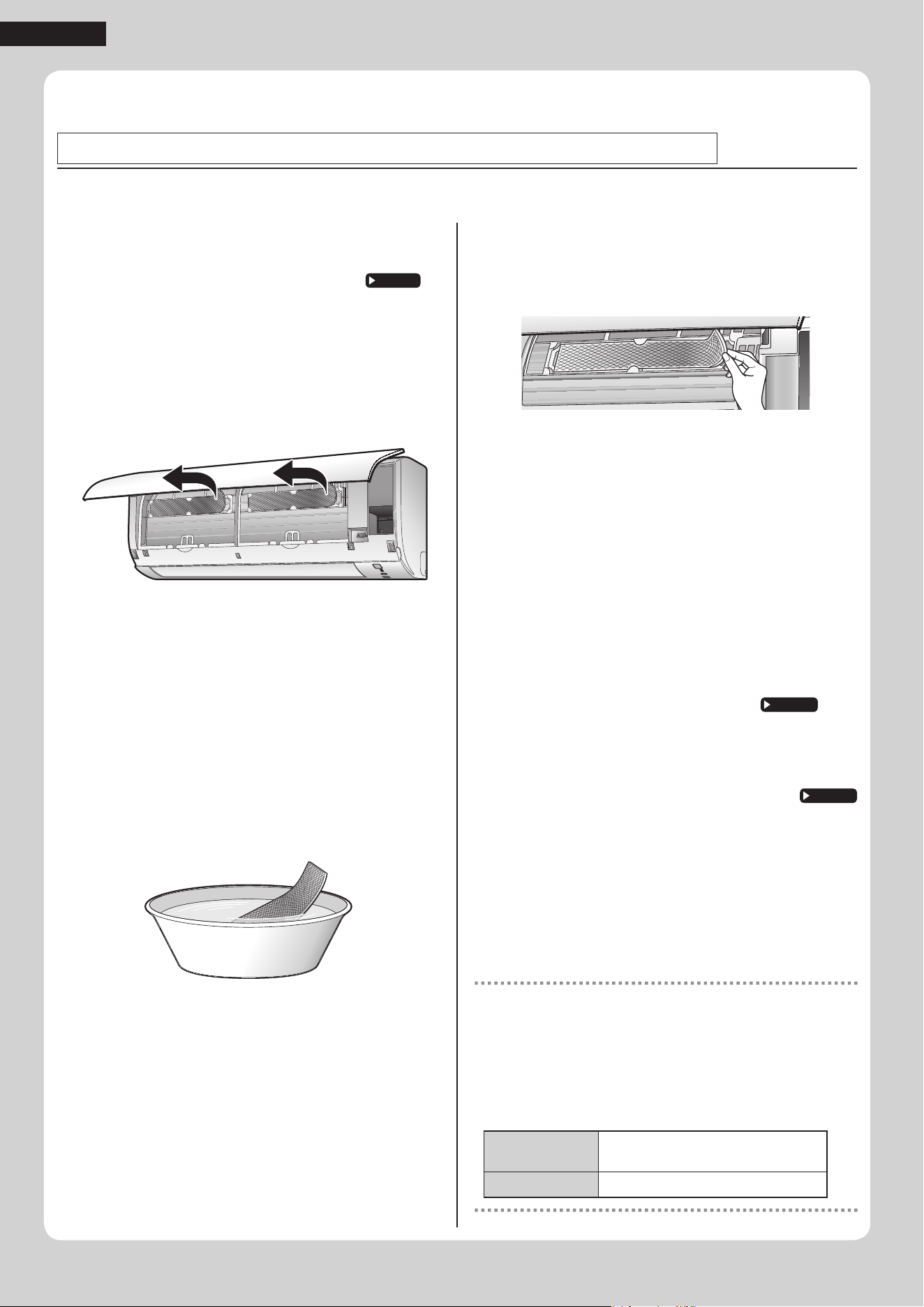
Titanium apatite photocatalytic air-purifying lter
1. Open the front panel and
pull out the air lters.
Page 20
2. Take off the titanium apatite
photocatalytic air-purifying
lters.
• Remove the lters from the tabs.
3. Clean or replace the
titanium apatite
photocatalytic air-purifying
lters.
[Cleaning]
3-1 Vacuum dust, and soak in lukewarm
water or water for about 10 to
15minutes if very dirty.
3-2 After washing, shake off remaining
water and let them dry in the shade.
• Do not wring out the lter to remove water from it.
[Replacement]
Remove the lter from the tabs
and prepare a new one.
• Dispose of the old lter as non- ammable waste.
4. Insert the titanium apatite
photocatalytic air-purifying
lters as they were.
• When attaching the lter, check that the lter is
properly set in the tabs.
5. Reattach the lters.
Page 20
6. Close the front panel slowly.
Page 20
NOTE
• Operation with dirty lters:
− cannot deodorize the air,
− cannot clean the air,
− results in poor heating or cooling,
− may cause odor.
• Dispose of old lters as non- ammable waste.
• To order a titanium apatite photocatalytic air-purifying lter, contact
the dealer where you bought the air conditioner.
Item
Titanium apatite photocatalytic
air-purifying lter 1set
Part No. KAF970A46 (without frame)
Care and Cleaning
FTX09NMVJU / FTX12NMVJU / FTXN09NMVJU / FTXN12NMVJU
01_EN_3P379751-4C.indd 21 11/6/2015 16:14:47
22
EnglishEnglish
Care
CAUTION
• Before cleaning, be sure to stop the operation and turn off the circuit breaker.
• Do not touch the aluminium ns of the indoor unit. If you touch those parts, this may cause an injury.
Quick reference
Cleaning parts
NOTE
For cleaning, do not use any of the following:
• Water hotter than 104°F (40°C)
• Volatile liquid such as benzene, petrol and thinner
• Polishing compounds
• Rough materials such as a scrubbing brush
Front panel
• Wipe it with a soft damp cloth.
• Only neutral detergent may be used.
If dirty
Air lter
• Vacuum dust or wash the lter.
Once every 2 weeks
Page 23
Indoor unit, outdoor unit
and remote controller
• Wipe them with a soft cloth.
If dirty
Titanium apatite photocatalytic air-purifying lter
(with frame)*
• Vacuum dust or replace the lter.
[Cleaning] [Replacement]
Once every 6 months Once every 3 years
Page 24
Page 24
*FTXN18/24NMVJU: Sold separately.
Care and Cleaning
FTX15NMVJU / FTX18NMVJU / FTX24NMVJU / FTXN18NMVJU / FTXN24NMVJU
01_EN_3P379751-4C.indd 22 11/6/2015 16:14:47
23
Care
Air lter
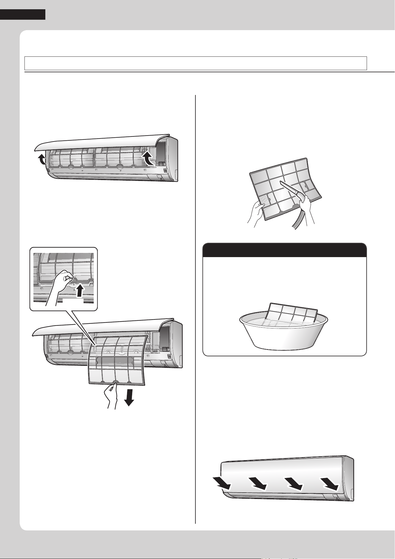
1. Open the front panel.
• Hold the front panel by the sides and open it.
2. Pull out the air lters.
• Push the lter tab at the center of each air lter a
little upwards, then pull it down.
2) Pull down
1) Push
3. Wash the air lters with
water or clean them with
vacuum cleaner.
• It is recommended to clean the air lters every
2weeks.
If the dust does not come off easily
• Wash the air lters with neutral detergent thinned with
lukewarm water, then dry them up in the shade.
• Be sure to remove the titanium apatite photocatalytic
air-purifying lter. Refer to “Titanium apatite
photocatalytic air-purifying lter” on the next page.
4. Reattach the lters.
5. Close the front panel slowly.
• Press the front panel at both sides and in the
central area.
• Make sure that the front panel is securely xed.
Care and Cleaning
FTX15NMVJU / FTX18NMVJU / FTX24NMVJU / FTXN18NMVJU / FTXN24NMVJU
01_EN_3P379751-4C.indd 23 11/6/2015 16:14:51
24
EnglishEnglish
Care
Titanium apatite photocatalytic air-purifying lter
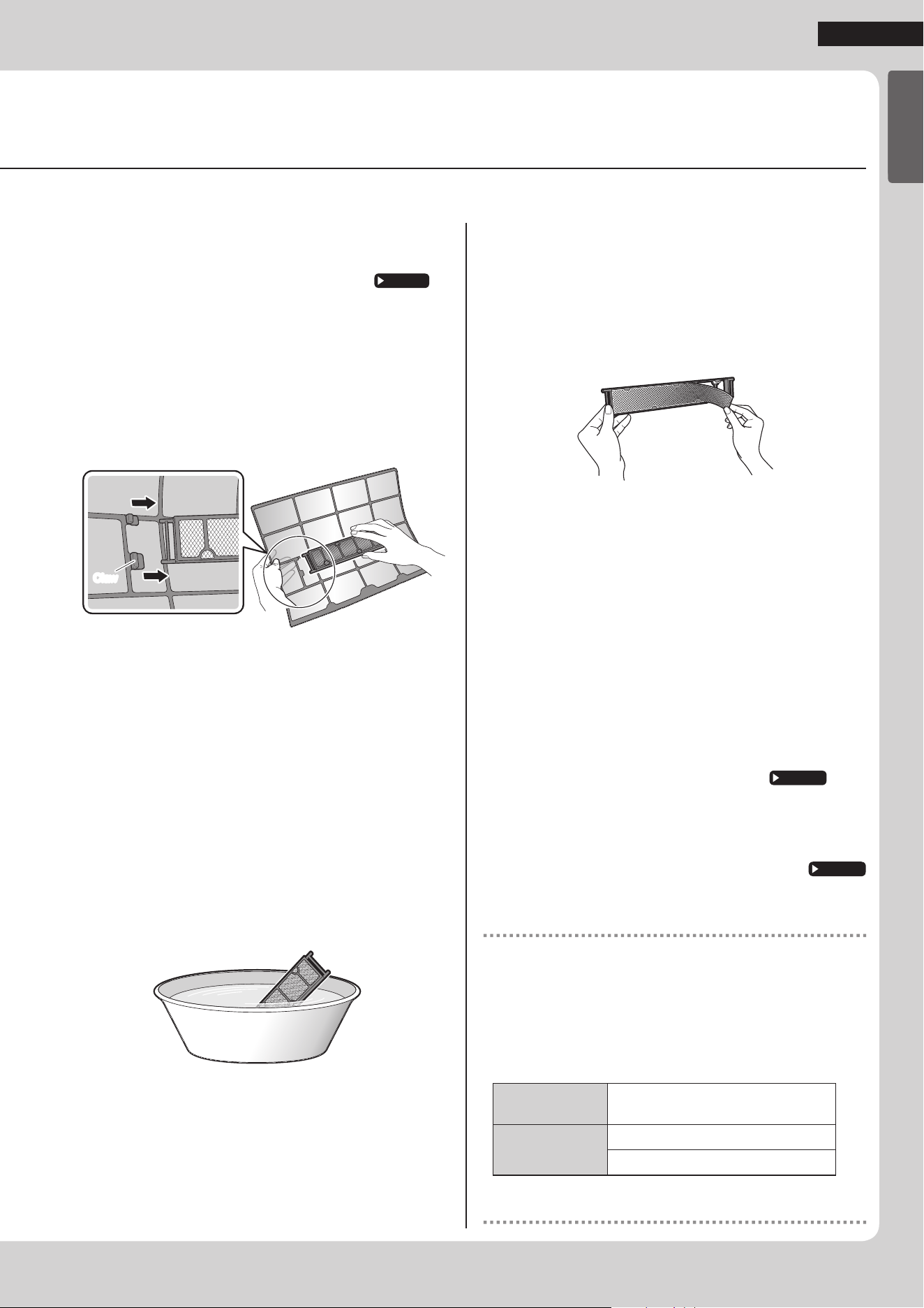
1. Open the front panel and
pull out the air lters.
Page 23
2. Take off the titanium apatite
photocatalytic air-purifying
lters.
• Hold the recessed parts of the frame and unhook
the 4claws.
ClawClaw
3. Clean or replace the
titanium apatite
photocatalytic air-purifying
lters.
[Cleaning]
3-1 Vacuum dust, and soak in lukewarm
water or water for about 10 to
15minutes if very dirty.
• Do not remove the lter from the frame when
washing with water.
3-2 After washing, shake off remaining
water and let them dry in the shade.
• Do not wring out the lter to remove water from it.
[Replacement]
Remove the lter from the lter
frame and prepare a new one.
• Do not throw away the lter frame. Reuse the lter
frame when replacing the titanium apatite
photocatalytic air-purifying lter.
• Dispose of the old lter as non- ammable waste.
4. Insert the titanium apatite
photocatalytic air-purifying
lters as they were.
• When attaching the lter, check that the lter is
properly set in the tabs.
5. Reattach the lters.
Page 23
6. Close the front panel slowly.
Page 23
NOTE
• Operation with dirty lters:
− cannot deodorize the air,
− cannot clean the air,
− results in poor heating or cooling,
− may cause odor.
• Dispose of old lters as non- ammable waste.
• To order a titanium apatite photocatalytic air-purifying lter, contact
the dealer where you bought the air conditioner.
Item
Titanium apatite photocatalytic
air-purifying lter 1set
Part No.
KAF970A46 (without frame)
KAF970A45 (with frame)*
*Users of FTXN18/24NMVJU, please purchase KAF970A45
(with frame) when purchasing the lter for the rst time.
01_EN_3P379751-4C.indd 24 11/6/2015 16:14:52
25
Care
Prior to a long period of non-use
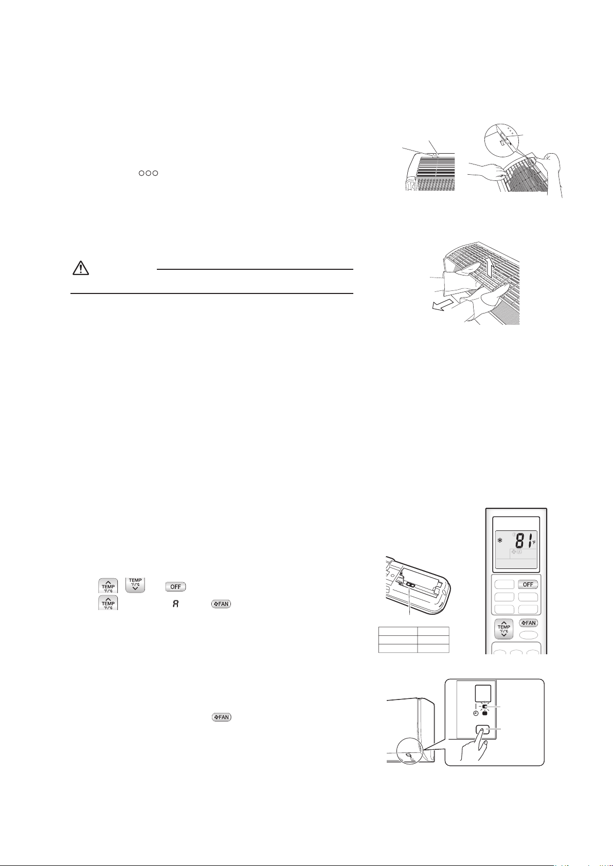
1. Operate the FAN ONLY mode for several hours to dry out the
inside.
• Press .
2. After operation stops, turn off the circuit breaker for the room
air conditioner.
3. Take out the batteries from the remote controller.
We recommend periodical maintenance
• In certain operating conditions, the inside of the air conditioner may get foul after several seasons of use, resulting in poor
performance. It is recommended to have periodical maintenance by a qualied contractor in addition to regular cleaning by
the user.
• For qualied contractor maintenance, please contact the dealer where you bought the air conditioner.
Care and Cleaning
All models
01_EN_3P379751-4C.indd 25 11/6/2015 16:14:52
26
EnglishEnglish
When the Need Arises
FAQ
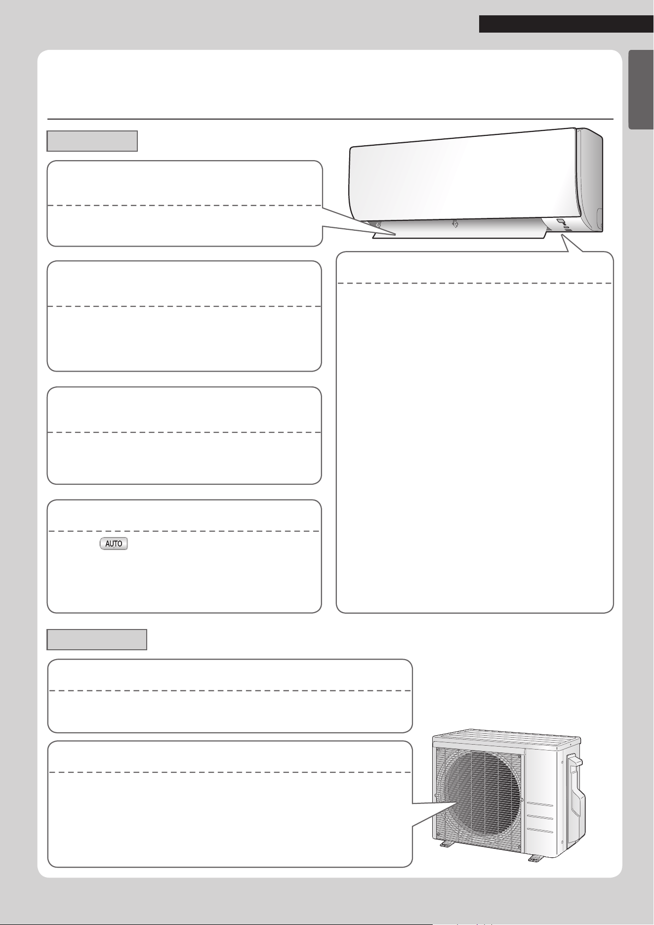
Indoor unit
Outdoor unit
Operation does not start soon.
When or any direct operation button was
pressed soon after operation was stopped.
When the mode was reselected.
• This is to protect the air conditioner.
You should wait for about 3minutes.
The ap does not start swinging
immediately.
• The air conditioner is adjusting the position of the ap.
The ap will start moving soon.
Different sounds are heard.
A sound like owing water
• This sound is generated because the refrigerant in the
air conditioner is owing.
•
This is a pumping sound of the water in the air
conditioner and can be heard when the water is
pumped out from the air conditioner during COOL or
DRY operation.
Blowing sound
• This sound is generated when the ow of the
refrigerant in the air conditioner is switched over.
Ticking sound
• This sound is generated when the cabinet and frame
of the air conditioner slightly expand or shrink as a
result of temperature changes.
Whistling sound
• This sound is generated when refrigerant ows during
defrosting operation.
Clicking sound during operation or idle time
• This sound is generated when the refrigerant control
valves or the electrical parts operate.
Clopping sound
•
This sound is heard from the inside of the air conditioner
when the exhaust fan is activated while the room doors are
closed. Open the window or turn off the exhaust fan.
The outdoor unit emits water or steam.
In HEAT operation
• The frost on the outdoor unit melts into water or steam when the air
conditioner is in defrosting operation.
In COOL or DRY operation
• Moisture in the air condenses into water on the cool surface of the outdoor
unit piping and drips.
Operating sound is loud.
• When frost forms on the heat exchanger of the outdoor unit, the operating
sound level increases slightly.
HEAT operation stops suddenly
and a
owing sound is heard.
• The outdoor unit is defrosting. HEAT operation starts
after the frost on the outdoor unit has been removed.
This can take about 4 to 12 minutes.
The air conditioner stops generating
airow during HEAT operation.
• Once the set temperature is reached, the airow rate is
reduced and operation stopped in order to avoid
generating a cool airow. Operation will resume
automatically when the indoor temperature falls.
01_EN_3P379751-4C.indd 26 11/6/2015 16:14:52
27
When the Need Arises
Before making an inquiry or a request for repair, please check the following.
If the problem persists, consult your dealer.
Not a problem
This case is not a problem.
Check
Please check again before requesting
repairs.
The air conditioner does not operate
Case Description / what to check
OPERATION lamp is off.
• Has the circuit breaker been tripped or the fuse blown?
• Is there a power failure?
• Are batteries set in the remote controller?
OPERATION lamp is blinking.
• Turn off the power with the circuit breaker and restart operation with the remote controller.
If the OPERATION lamp is still blinking, check the error code and consult your dealer.
Page 30
The air conditioner suddenly stops operating
Case Description / what to check
OPERATION lamp is on.
• To protect the system, the air conditioner may stop operating after sudden large voltage
uctuations. It automatically resumes operation in about 3 minutes.
OPERATION lamp is blinking.
• Is there anything blocking the air inlet or air outlet of the indoor unit or outdoor unit?
Stop operation and after turning off the circuit breaker, remove the obstruction. Then restart
operation with the remote controller. If the OPERATION lamp is still blinking, check the error
code and consult your dealer.
Page 30
The air conditioner does not stop operating
Case Description / what to check
The air conditioner continues
operating even after operation is
stopped.
Immediately after the air conditioner is stopped
• The outdoor unit fan continues rotating for about another 1 minute to protect the system.
While the air conditioner is not in operation
• When the outdoor temperature is high, the outdoor unit fan may start rotating to protect
the system.
The room does not cool down / warm up
Case Description / what to check
Air does not come out.
In HEAT operation
• The air conditioner is warming up. Wait for about 1 to 4 minutes.
• During defrosting operation, hot air does not ow out of the indoor unit.
Air does not come out /
Air comes out.
Is the air ow rate setting appropriate?
• Is the air ow rate setting low, such as “Indoor unit quiet” or “Air ow rate 1”? Increase the
air ow rate setting.
Is the set temperature appropriate?
Is the adjustment of the air ow direction appropriate?
Air comes out.
• Is there any furniture directly under or beside the indoor unit?
• Is the air conditioner in ECONO operation?
Page 16
• Are the air lters dirty?
• Is there anything blocking the air inlet or air outlet of the indoor unit or outdoor unit?
• Is a window or door open?
• Is an exhaust fan turning?
Troubleshooting
01_EN_3P379751-4C.indd 27 11/6/2015 16:14:53
28
English
When the Need Arises
Mist comes out
Case Description / what to check
Mist comes out of the indoor unit.
• This happens when the air in the room is cooled into mist by the cold air ow during COOL
or other operation.
Remote controller
Case Description / what to check
The unit does not receive signals
from the remote controller or has
a limited operating range.
• The batteries may be exhausted.
Replace both batteries with new dry batteries AAA.LR03 (alkaline).
For details, refer to “Preparation Before Operation”.
Page 10
• Signal communication may be disabled if an electronic-starter-type uorescent lamp (such
as inverter-type lamps) is in the room. Consult your dealer if that is the case.
• The remote controller may not function correctly if the transmitter is exposed to direct
sunlight.
LCD is faint, is not working, or the
display is erratic.
• The batteries may be exhausted.
Replace both batteries with new dry batteries AAA.LR03 (alkaline).
For details, refer to “Preparation Before Operation”.
Page 10
Other electric devices start
operating.
• If the remote controller activates other electric devices, move them away or consult your
dealer.
Air has an odor
Case Description / what to check
The air conditioner gives off an
odor.
• The room odor absorbed in the unit is discharged with the air ow.
We recommend you to have the indoor unit cleaned. Please consult your dealer.
Others
Case Description / what to check
The air conditioner suddenly
starts behaving strangely during
operation.
• The air conditioner may malfunction due to lightning or radio.
If the air conditioner malfunctions, turn off the power with the circuit breaker and restart the
operation with the remote controller.
Notes on the operating conditions
• If operation continues under any conditions other than those listed in
the table,
− A safety device may activate to stop the operation.
− Dew may form on the indoor unit and drip from it when COOL or
DRY operation is selected.
Mode Operating conditions
COOL / DRY
Outdoor temperature: 50-115°F (10-46°C)
Indoor temperature: 64-90°F (18-32°C)
Indoor humidity: 80% max.
HEAT
Outdoor temperature: [RX, RXN]: 5-75°F (–15-24°C)
[RXL]: –13-75°F (–25-24°C)
Indoor temperature: 50-86°F (10-30°C)
01_EN_3P379751-4C.indd 28 11/6/2015 16:14:53
29
When the Need Arises
Troubleshooting
Call your dealer immediately
WARNING
When an abnormality (such as a burning smell) occurs, stop operation and turn off the circuit breaker.
• Continued operation in an abnormal condition may result in problems, electric shock or re.
• Consult the dealer where you bought the air conditioner.
Do not attempt to repair or modify the air conditioner by yourself.
• Incorrect work may result in electric shock or re.
• Consult the dealer where you bought the air conditioner.
If one of the following symptoms takes place, call your dealer immediately.
• The power cord is abnormally hot or damaged.
• An abnormal sound is heard during operation.
• The circuit breaker, a fuse, or the ground fault circuit
interrupter cuts off the operation frequently.
• A switch or a button often fails to work properly.
• There is a burning smell.
• Water leaks from the indoor unit.
Turn off the circuit breaker and call your dealer.
After a power failure
• The air conditioner automatically resumes operation in about 3minutes. You should just wait for a while.
Lightning
• If there is a risk lightning could strike in the neighborhood, stop operation and turn off the circuit breaker to protect the
system.
Disposal requirements
• Dismantling of the unit, handling of the refrigerant, oil and other parts, should be done in accordance with the relevant local
and national regulations.
01_EN_3P379751-4C.indd 29 11/6/2015 16:14:53
30
English
When the Need Arises
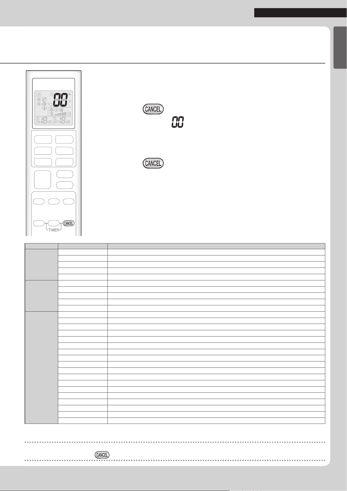
Fault diagnosis by remote controller
• The remote controller can receive relevant error codes from the indoor unit.
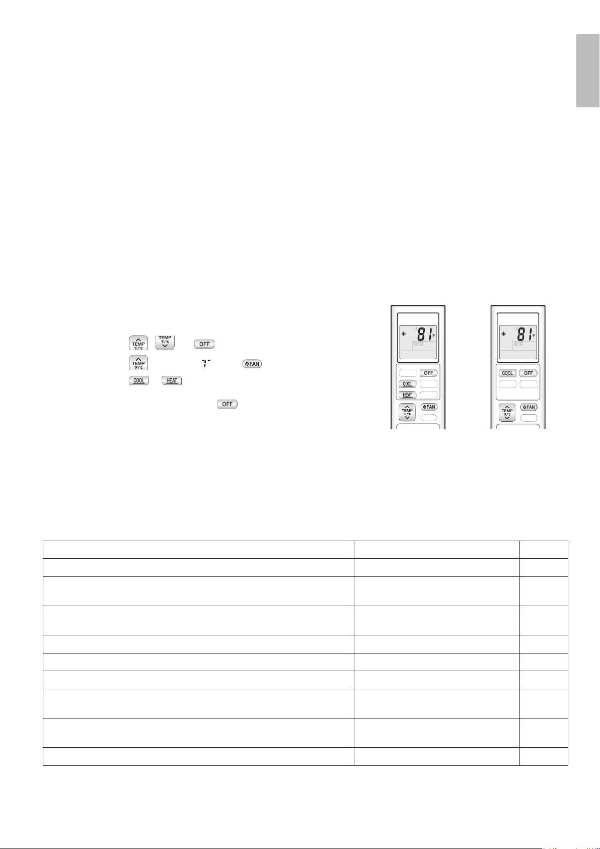
1. When is held down for about
5 seconds, “ ” blinks in the temperature
display section.
2. Press repeatedly until a continuous beep
is produced.
• The code indication changes as shown below, and noties you with a long beep.
CODE
MEANING
SYSTEM
00
NORMAL
UA
INDOOR-OUTDOOR UNIT COMBINATION FAULT
U0
REFRIGERANT SHORTAGE
U2
DROP VOLTAGE OR MAIN CIRCUIT OVERVOLTAGE
U4
FAILURE OF TRANSMISSION (BETWEEN INDOOR UNIT AND OUTDOOR UNIT)
INDOOR
UNIT
A1
INDOOR PCB DEFECTIVENESS
A5
HIGH PRESSURE CONTROL OR FREEZE-UP PROTECTOR
A6
FAN MOTOR FAULT
C4
FAULTY HEAT EXCHANGER TEMPERATURE SENSOR
C9
FAULTY SUCTION AIR TEMPERATURE SENSOR
OUTDOOR
UNIT
EA
COOLING-HEATING SWITCHING ERROR
E1
CIRCUIT BOARD FAULT
E5
OL STARTED
E6
FAULTY COMPRESSOR START UP
E7
DC FAN MOTOR FAULT
E8
OVERCURRENT INPUT
F3
HIGH TEMPERATURE DISCHARGE PIPE CONTROL
F6
HIGH PRESSURE CONTROL (IN COOLING)
H0
SENSOR FAULT
H6
OPERATION HALT DUE TO FAULTY POSITION DETECTION SENSOR
H8
DC CURRENT SENSOR FAULT
H9
FAULTY SUCTION AIR TEMPERATURE SENSOR
J3
FAULTY DISCHARGE PIPE TEMPERATURE SENSOR
J6
FAULTY HEAT EXCHANGER TEMPERATURE SENSOR
L3
ELECTRICAL PARTS HEAT FAULT
L4
HIGH TEMPERATURE AT INVERTER CIRCUIT HEATSINK
L5
OUTPUT OVERCURRENT
P4
FAULTY INVERTER CIRCUIT HEATSINK TEMPERATURE SENSOR
NOTE
• A short beep indicates non-corresponding codes.
• To cancel the code display, hold
down for about 5 seconds. The code display also clears if no button is pressed for 1 minute.
01_EN_3P379751-4C.indd 30 11/6/2015 16:14:53
3P379751-4C M15B132
(1511)
HT
The two-dimensional bar code is
a manufacturing code.
00_CV_3P379751-4C.indd 2 10/22/2015 11:54:38