Loading ...
Loading ...
Loading ...

8.1 BACKLIGHT AND INSPECTION LIGHT
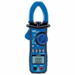
Press and hold the " " button to switch on and off the back light/inspection light.
Note: The inspection light will only come on while in AC current function.
8.2 FUNCTION SWITCH BUTTON (SEL)
The "SEL" button is for switching between DCV/ACV,also between diode and continuity
measuring.
8.3 MAX READINGS MAXIMUM VALUE DISPLAY
Press the "MAX" key to display the maximum value of measurement data on the display.
8.4 AUTO/MANUAL SWITCH BUTTON (RAN)
At the voltage, resistance measurement ranges, clamp meter defaults to auto range. Press
this button to switch to manual range. In the manual range, press this button that means
jump upwards one section, if the highest section jumps to the lowest section. Press and
hold this button for more than 2 seconds, that is, switch back to automatic range.
8.5
AC CURRENT MEASUREMENT USING CURRENT CLAMP HEAD.
Warning
YOU MUST NOT measure current using the probes.
Remove the test leads from the meter when measuring with the clamp head.
1. Rotate the measurement function selection dial to the appropriate current.
2. Press the trigger to open the clamp, pass the wire to be measured into the centre of the
clamp, and then slowly release the trigger until the clamp is fully closed.
3. Read the measurement result from the LCD.
Note: The instrument can only measure one current conductor at a time.
If two or more current conductors are measured at the same time, the measurement will be
inaccurate.
8.6 DC VOLTAGE MEASUREMENT
Warning
Risk of electric shock.
When measuring high voltage, extra care should be taken to avoid electrical shock.
Do not attempt to use this meter on a voltage higher than DC600V rms.
1. Rotate the measurement function selection dial to the DC voltage measurement.
2. Connect the black lead to the COM probe socket and the red lead to the
INPUT probe
socket.
3. The measured value is read from the LCD. The polarity display will indicate the polarity
of the terminals to which the red test is connected.
8. OPERATING INSTRUCTIONS
12
Loading ...
Loading ...
Loading ...
