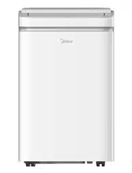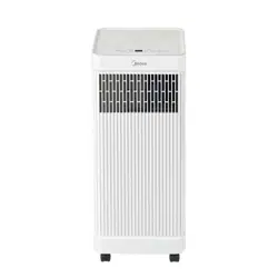
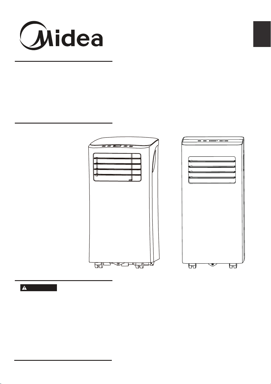
Portable
MAP05R1WT
MAP08R1CWT
www.midea.com
USER MANUAL
en
PH
Before using this product,
please read this manual carefully
and keep it for future reference.
The design and specifications
are subject to change without
prior notice for product
improvement. Consult with
your dealer or the manufacturer
for details.
Rated voltage: 115V
Frequency: 60Hz
WARNING
Page 2
Read This Manual
Inside you’ll find many helpful hints on how to use and maintain your air conditioner
properly. Just a little preventive care on your part can save you a great deal of time
and money over the life of your air conditioner. You’ll find many answers to common
problems in the chart of troubleshooting tips - you should be able to fix most of
them quickly before calling service. These instructions may not cover every possible
condition of use, so common sense and attention to safety is required when installing,
operating and maintaining this product.
Owner’s Manual
Safety Precautions ....................................................................................... 3
Unit Specifications and Features .............................................................. 8
Operating Instructions ................................................................................ 9
Installation Instructions ............................................................................... 12
Care and Cleaning ....................................................................................... 17
Troubleshooting Tips .................................................................................. 18
Remote Control Instructions ..................................................................... 19
27
Warranty ................................................................... and Return Policy ...
• For support, please call the Service Center at 1-866-646-4332.
• This appliance is not intended for use by people (including children) with reduced
physical, sensory or mental capabilities or lack of experience and knowledge, unless
they have been given supervision or instruction concerning use of the appliance by
a person responsible for their safety.
• Children should be supervised to ensure that they do not play with the air conditioner.
• The appliance shall be installed in accordance with national wiring regulations.
• Do not operate your air conditioner in a humid room such as a bathroom or laundry
room.
CAUTION
Page 3
Safety
Precautions
Safety Precautions
To prevent injury to the user or other people and property damage, the instructions
shown here must be followed. Incorrect operation due to ignoring of instructions may
cause harm or damage. The level of risk is shown by the following indications.
• Plug in power cord plug properly.
Otherwise, it may cause electric shock or fire due to excess heat generation.
• Do not modify power cord length or share the outlet with other appliances as it
may cause electric shock or fire due to overheating.
• Always ensure effective grounding.
Incorrect grounding may cause electric shock.
• Unplug the unit if you notice unusual sounds or smells, or smoke comes from it.
A damaged product may cause fire and electric shock.
• Keep firearms away from the unit.
• Ventilate room before operating the air conditioner if there is a gas leakage from
another appliance.
• Do not operate or stop the unit by inserting or pulling out the power cord plug.
• Do not operate with wet hands or in very humid enviroments.
It may cause electric shock.
• Do not allow water to come into contact with any electric parts.
It may cause failure or electric shock.
• Do not use the socket if it is loose or damaged.
It may cause fire and electric shock.
• Do not place the power cord close to heating appliances.
It may cause fire and electric shock
• Do not disassemble or modify unit.
It may cause failure and electric shock.
WARNING
WARNING
This symbol indicates a hazardous situation which, if not
avoided, could result in death or serious injury.
CAUTION
This symbol indicates a hazardous situation, which, if not
avoided, could result in minor or moderate injury.
NOTICE
This symbol addresses practices not related to physical
injury.
Page 4
Safety
Precautions
WARNING
• Do not damage or use an alternate power cord.
It may cause fire and electric shock.
If the power cord is damaged, it must be replaced by the manufacturer or an
authorized service center or a similarly qualified person in order to avoid a hazard.
• Do not direct airflow straight into persons to avoid possible health hazard.
• Do not open the unit during operation.
It may cause electric shock.
• Do not use the power cord near flammable gas or combustibles, such as gasoline,
benzene, thinner, etc.
It may cause an explosion or fire.
• Avoid fire hazard or electric shock. Do not use an extension cord or an adaptor
plug. Do not remove any prongs from the power cord.
• Be sure the air conditioner is properly grounded. To minimize shock and fire
hazards, proper grounding is important. The power cord is equipped with a
three-prong grounding plug for protection against shock hazards.
• Your air conditioner must be used in a properly grounded wall receptacle. If the
wall receptacle you intend to use is not adequately grounded or protected by a
time delay fuse or circuit breaker, have a qualified electrician install the proper
receptacle. Ensure the receptacle is accessible after the unit installation.
• Be sure the electrical service is adequate for the model you have chosen. This
information can be found on the serial plate, which is located on the side of the
cabinet and behind the grille.
CAUTION
• When the air filter is to be removed, do not touch the metal parts of the unit.
It may cause injury.
• When the unit needs cleaning, switch off, and turn off the circuit breaker.
Do not clean unit when power is on as it may cause fire, electric shock or injury.
• Do not place obstacles around air inlets or inside of air outlet.
It may cause failure or accident.
• Clean with a soft cloth only. Do not use strong detergents that
contain wax or
thinners as it may damage the product.
• Use caution when unpacking and installing. Sharp edges could cause injury.
• Do not clean the air conditioner with water.
Water may enter the unit and degrade the insulation which could lead to
electric shock.
• D
o not drink water drained from the air conditioner.

Page 5
Safety
Precautions
CAUTION
• Do not put a pet or house plant where it will be exposed to direct air flow.
This could injure the pet or harm the plant.
• Hold the plug by the head of the power plug when taking it out.
Otherwise, it may cause electric shock and damage.
• Ensure that the installation is properly secured to prevent the product from
potentially falling.
• Do not place heavy objects on the power cord and ensure that the cord is not
compressed.
Otherwise, there is danger of fire or electric shock.
• If water is spilled on the unit, turn off the unit and switch off the circuit breaker.
Isolate supply by taking the power-plug out and contact a qualified service
technician.
• Do not use near gas stove or other gas burning appliances,
as air flow may affect
gas combustion.
• Do not use for any purpose other than room comfort.
Do not use this air conditioner to
preserve precision devices, food, pets, plants,
and art objects. It may cause deterioration.
• Turn off the main power switch if the unit is not to be used for an extended time.
• Always insert the filters securely. Clean filter once every two weeks.
Operation without filters may cause failure.
Page 6
Safety
Precautions
NOTICE
• Do not use this device to turn the unit on or off.
• Always make sure the RESET button is pushed in for correct operation.
• The power supply must be replaced if it fails to reset when either the TEST button
is pushed, or it can not be reset. Please contact Customer Service.
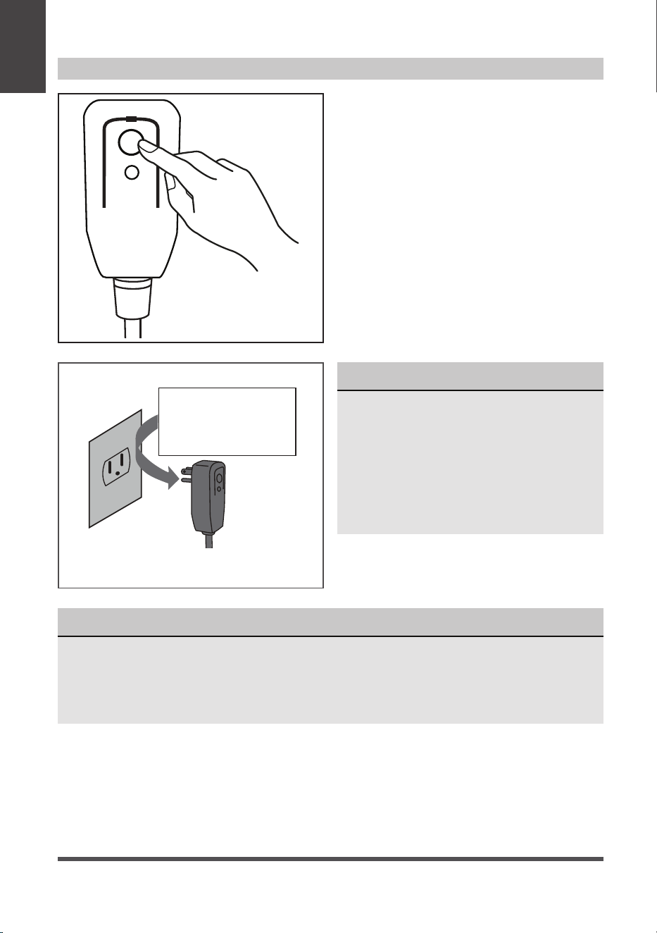
NOTICE
The power supply cord with this
air conditioner contains a current
detection device designed to reduce
the risk of fire.
In the event that the power supply
cord is damaged, it can not be
repaired. It must be replaced with a
cord from the manufacturer.
Grounding type wall receptacle
Do not, under any
circumstances, cut,
remove or bypass
the grounding prong.
Power supply cord with 3-prong grounding
plug and current detection device.
The power supply cord contains a
measurement current device that senses
damage to the power cord. Test your power
supply cord as follows:
1. Plug in the air conditioner.
2. The power supply cord will have TWO
buttons on the plug head. Press the
TEST button. You will notice a click as
the RESET button pops out.
3. Press the RESET Button. You will
notice a click as the button engages.
4. The power supply cord is now
supplying electricity to the unit. (On
some products this is also indicated
by a light on the plug head.)
RESE T
TE ST
Plug in &
press RESET
Operation of Current Device
Page 7
Safety
Precautions
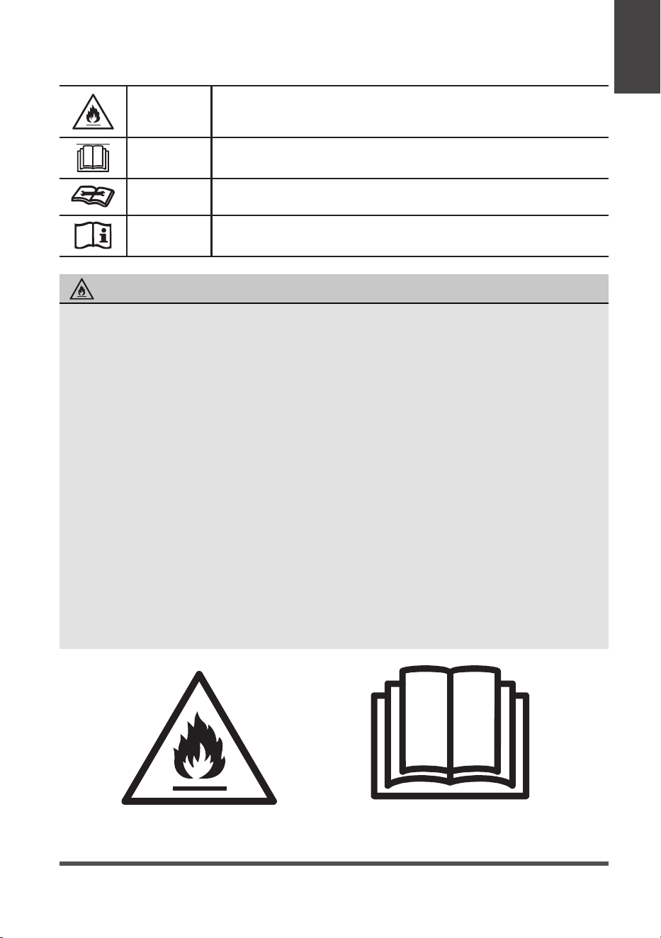
WARNING
This symbol shows that this appliance used a flammable
refrigerant. If the refrigerant is leaked and exposed to an
external ignition source, there is a risk of fire.
CAUTION
This symbol shows that the operation manual should be read
carefully.
CAUTION
This symbol shows that a service personnel should be handling
this equipment with reference to the installation manual.
CAUTION
This symbol shows that information is available such as the
operating manual or installation manual.
EXPLANATION OF SYMBOLS DISPLAYED ON THE UNIT
• Do not try to accelerate the defrosting process or methods of cleaning that are
not recommended by the manufacturer.
• The appliance shall be stored in a room without a continuously operating ignition
source (for example, open flames or an operating gas appliance) or an ignition
source (for example, an operating electric heater) close to the appliance. The
appliance shall also be stored in a room without ignition sources.
• Do not pierce or burn.
• Be aware that the refrigerants may not contain an odor.
• Keep ventilation openings clear of o
bstruction.
• Unit is only to be serviced by a Midea authorized servicer, please call Customer
Service at 1-866-646-4332 for support.
• Flammable refrigerant R32 is used within air conditioner. Please follow the
instructions carefully to handle, install, clean, and service the air conditioner
to avoid damage or hazard. Do not dispose of air conditioner in r
egular trash.
Contact qualified agency for proper disposal.
• No open fire or devices that generate spark/arcing shall be around the air
conditioner to avoid causing ignition of the flammable refrigerant used. Please
follow the instructions ca
refully to store or maintain the air conditioner to
prevent mechanical damage from occurring.
WARNING (for using R32 refrigerant only)
Caution: Risk of fire/
flammable materials
(Required for R32/R290 units only)
IMPORTANT NOTE:Read this manual
carefully before installing or operating
your new air conditioning unit. Make sure
to save this manual for future reference.
Preparation
Design and Compliance Notes
Unit
Specifications
and Features
Design Notice:
In order to ensure the optimal performance of our products, the design specifications of
the unit and remote control are subject to change without prior notice.
Energy Rating Information:
This product is tested in accordance to the DOE SACC capacity energy rating test.
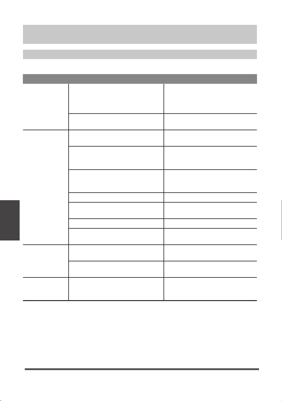
Unit Temperature Range:
Mode
Temperature Range
Cool
17°C ~ 35°C (62°F ~ 95°F)
Dry
13°C ~ 35°C (55°F ~ 95°F)
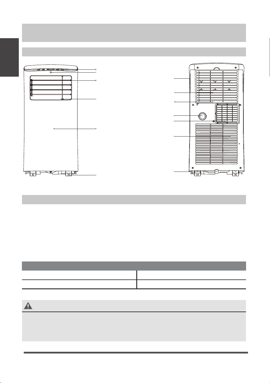
raeRtnorF
control panel
remote signal receptor
handle
(both sides)
outlet louver - vertical
direction control lever
(adjust manually)
NOTE: PHA cannot be
adjusted.
outlet louver - horizontal
direction control lever
(adjust manually)
NOTE: PHA cannot be
adjusted.
panel
Caster
bottom tray
drain outlet
air filter
(behind the grille)
upper air intake
air outlet
lower air intake
drain outlet
Unit Specifications and Features
Page 8
The exhaust hose and adaptor must be installed or removed in accordance with the
usage mode.
For COOL or AUTO mode, exhaust hose must be installed.
For FAN or DEHUMIDIFY exhaust hose must be removed.
EXHAUST HOSE INSTALLATION:
Cool
Fan
Dry
On | OffMode
Operating
Instructions
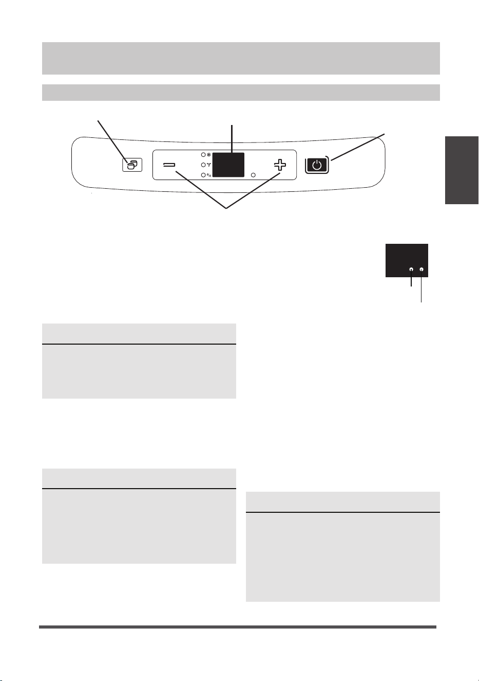
Control Panel Features
Mode Button
Selects the desired operating mode.
Each time you press the button, a mode
is selected in a sequence that goes from
COOL, FAN and DRY. The mode light
illuminates and indicates the selected
mode.
Up (+) and Down (-) Buttons
Used to adjust (increasing/decreasing)
temperature settings in 1°C/1°F increments
in a range of 17°C/62°F to 30°C/86°F.
NOTE
The control is capable of displaying
temperature in degrees Fahrenheit or
degrees Celsius. To convert from one
to the other, press and hold the Up
and Down buttons at the same time
for 3 seconds.
NOTE
On above modes, the unit operates
the auto fan speed automatically. You
can set fan speed only by the remote
controller on COOL and FAN modes.
Power Button
Power switch on/off.
Power
indicator light
Timer mode indicator
light (set only by
remote controller)
LED display
Shows the set
temperature while on cool
mode. While on DRY and
FAN modes, it shows the
room temperature.
NOTE
When one of the above malfunctions
occurs, turn off the unit and check for
any obstructions. Restart the Unit. If the
malfunction persists, turn off the unit
and unplug the power cord. Contact
the manufacturer or its service agents
or a similar qualified person for service.
LED Display
Up (+) and Down (-) Control
Power
Button
Mode
Selector
Shows Error codes:
E1 - Room temperature sensor error.
E2 - Evaporator temperature sensor error.
E3 - Condenser temperature sensor error.
E4 - Display panel communication error.
Shows protection code:
P1 - Bottom tray is full - Connect the drain
hose and drain the collected water
away. If protection code repeats, call
for service.
Operating Instructions
Page 9
Constant Fan

Operating
Instructions
COOL operation
• Press the “MODE” button until the “COOL”
indicator light comes on.
• Press the UP and DOWN buttons “+” or “-” to
select your desired room temperature. The
temperature can be set within a range of
17°C~30°C/62°F~86°F.
• The fan speed is automatically set to auto.
Use the remote to adjust the fan speed if
desired.
DRY operation
• Press the “MODE” button until the “DRY”
indicator light comes on.
• While in this mode, you cannot select a
fan speed or adjust the temperature. The
fan motor operates at LOW speed.
• Keep windows and doors closed for the
best dehumidifying effect.
FAN operation
• Press the “MODE” button until the ”FAN“
indicator light comes on.
• Press the “FAN SPEED” button to
choose
the fan speed. The temperature cannot
be adjusted.
Operating Instructions
SLEEP/ECO operation
This feature can be activated from
the remote control ONLY. To activate
SLEEP feature, the set temperature will
increase by 1°C/2°F in 30 minutes. The set
temperature will then increase by another
1°C/2°F after an additional 30 minutes.
This new temperature will be maintained
for 7 hours before it returns to the
originally selected temperature. This ends
the Sleep mode and the unit will continue
to operate as originally programmed.
NOTE
This feature is unavailable in FAN or
DRY mode.
Other Features
NOTE
This feature can be activated from
the remote control ONLY. The remote
control serves as a remote thermostat
allowing for the precise temperature
control at its location.
COMFORTSENSE
Feature (only for some models)
To activate the Temp Sensing feature, point
the remote control towards the unit and
press the Temp Sensing button. The remote
display is actual temperature at its location.
The remote control will send this signal to
the air conditioner every 3 minutes until the
ComfortSense button is pressed again.
If the unit does not receive the Temp
Sensing signal during any 7 minutes interval,
the unit will exit the Temp Sensing mode.
Constant Fan button
Feature (optional) in cooling or Dry mode,
press the button for 3 seconds to turn on or
off the constant fan function. When the
function is turned on, the constant fan light
will illuminate, identifying the fan continuous
run for cooling. When the function is turned
off, the constant fan light will go out,
identifying the fan cycle run with
compressor stop.
AUTO-RESTART
If the unit shuts off unexpectedly due to a
power outage, it will restart with the previous
set function when the power resumes.
WAIT 3 MINUTES BEFORE RESUMING
OPERATION
After the unit has stopped, it cannot be
restarted until 3 minutes time has elapsed.
This is to protect the unit. Operation will
automatically resume after 3 minutes.
AIRFLOW DIRECTION ADJUSTMENT
Adjust the air flow direction manually:
- The louver can be set to the desired
position manually.
- Do not place any heavy objects or
other loads on the louver, doing so will
cause damage to the unit.
- Keep the louver fully opened during
operation.
Page 10
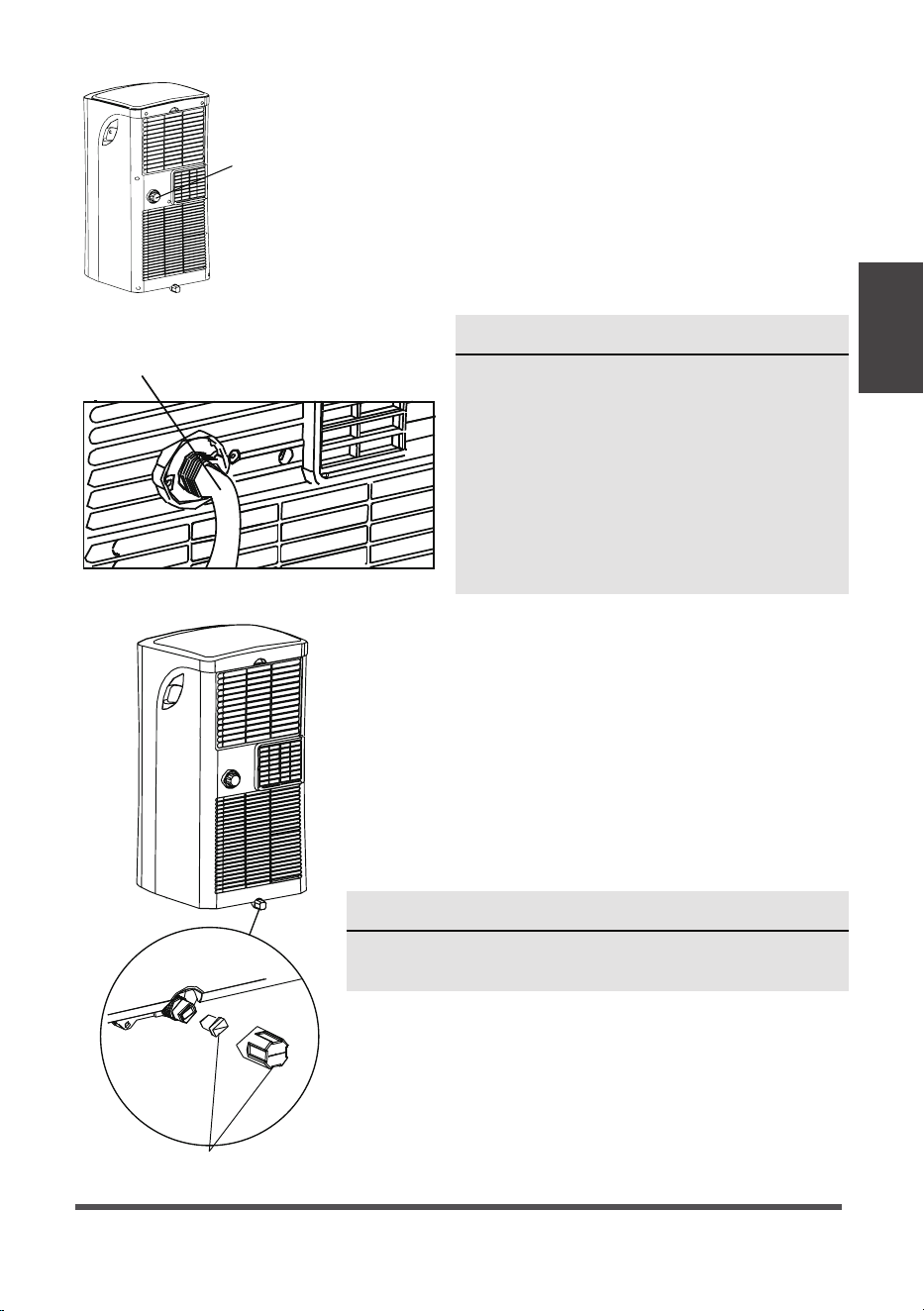
NOTE
Make sure the hose is secure so there are
no leaks. Direct the hose toward the drain,
making sure that there are no kinks that
will restrict water flow. Place the end of the
hose into the drain making sure the end of
the hose is directed downward. When the
continuous drain hose is not used, ensure
that the corresponding drain plug and knob
are securely installed to prevent leaks.
Water drainage
• During DRY mode, remove the upper drain plug from
the back of the unit and install the drain connector
(5/8” universal female adapter) with a 3/4“ hose
(not included). For models without the drain connector,
attach the drain hose to the connector. Place the end of
the hose in the drain area you’re using.
Remove the
drain plug
Continuous
drain hose
• When the water level of the bottom tray reaches
a predetermined level, the unit beeps 8 times.
The digital display shows “P1.” At this time the
air conditioning/dehumidification process will
immediately stop. However, the fan motor will
continue to operate (this is normal). Carefully move
the unit to a drain location, remove the bottom
drain plug and let the water drain away. Reinstall
the bottom drain plug and restart the machine until
the “P1” symbol disappears. If the error repeats, call
for service.
Bottom drain plug
NOTE
Be sure to reinstall the bottom drain plug firmly to
prevent leakage before using the unit.
Operating
Instructions
Page 11
Installation
Instructions
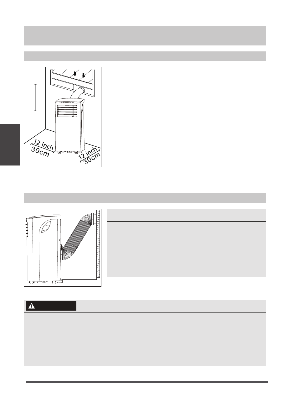
Your installation location should meet the following
requirements:
• Ma
• The unit must be near a window to install the exhaust
hose and window kit into.
ke sure that you install your unit on an even surface
to minimize noise and vibration.
• The unit must be installed near a grounded plug, and
the Collection Tray Drain (found on the back of the
unit) must be accessible.
• The unit should be located at least 12” (30cm) from
the nearest wall to ensure proper air conditioning.
Obstacles should be at least 19.7” (50cm) away from
the outlet louver.
• DO NOT cover the Intakes, Outlets or Remote Signal
Receptor of the unit, as this could cause damage to
the unit.
Choosing the Right Location
Recommend Installation
• This air-conditioning unit is a hermetically sealed unit that contains fluorinated
gasses. For specific information on the type of gas and the amount, please refer
to the relevant label on the unit itself.
• Service, maintenance and repair of this unit must be performed by a certified
technician.
• Product recycling must be done according to local regulations.
NOTE
All the illustrations in the manual are for explanation
purpose only. Your machine may be slightly different.
The unit can be controlled by the unit control panel
alone or with the remote controller. See the
Remote Controller Instruction for details.
50cm
19.7inch
Installation Instructions
50cm
19.7inch
Page 12
WARNING

Installation
Instructions
Page 13
• Medium Phillips screwdriver
• Tape measure or ruler
• Knife or scissors
• Saw (optional, to shorten window adaptor for narrow windows).
Your Window Installation Kit fits windows 67.5-123 cm (26.5”-48”) and can be shortened
for smaller windows.
Tools Needed
Accessories
Part Description
Unit adaptor
Window slider adaptor
Window slider A
Exhaust hose
Bolt
Foam seal A (adhesive)
Foam seal B (adhesive)
Foam seal C (Non-adhesive)
Security bracket and 2 screws
Drain hose
1 pc
1 pc
1 pc
1 set
1 pc
2 pcs
1 set
1 set
Quantity
remote control and batteries
(For remote control models only)
TEMP
3 pcs
4 pcs
2 pcs
Installation
Instructions
Page 14
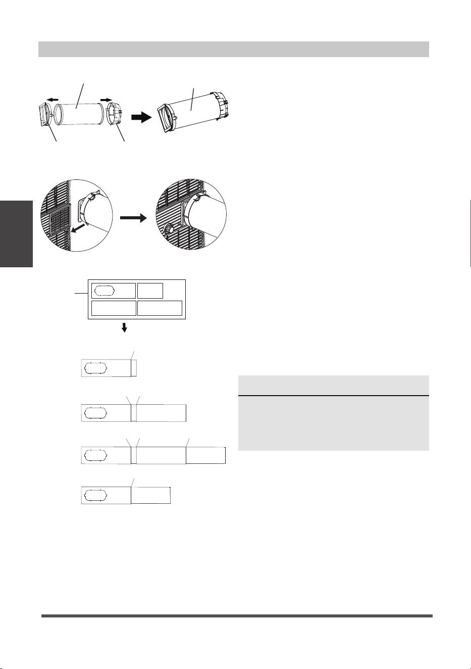
Step O
ne: Preparing the exhaust hose
assembly
Press the exhaust hose into the window
slider adaptor and unit adaptor, clamp
automatically by elastic buckles of the
adaptors.
Step Two: Install the exhaust hose
assembly to the unit
Push the Exhaust hose into the air
outlet opening of the unit along the
arrow direction.
Step Three: Preparing the adjustable
window slider
1. Depending on the size of your window,
you may need to adjust the size of the
window slider.
2. I
f the length of the window requires
two window sliders, use the bolt to
fasten the window sliders once they
are adjusted to the proper length.
Window Installation Kit
Unit
adaptor
Window slider
adaptor
Exhaust hose Exhaust hose
assembly
NOTE
Once the Exhaust Hose assembly and
Adjustable Window Slider are prepared,
choose from one of the following two
installation methods.
1+2:
Bolt
1+2+3:
Bolt
Bolt
1+2+3+4:
Bolt
BoltBolt
1+4:
Bolt
Window Sliders
After assembly
Before assembly
Installation
Instructions
Page 15
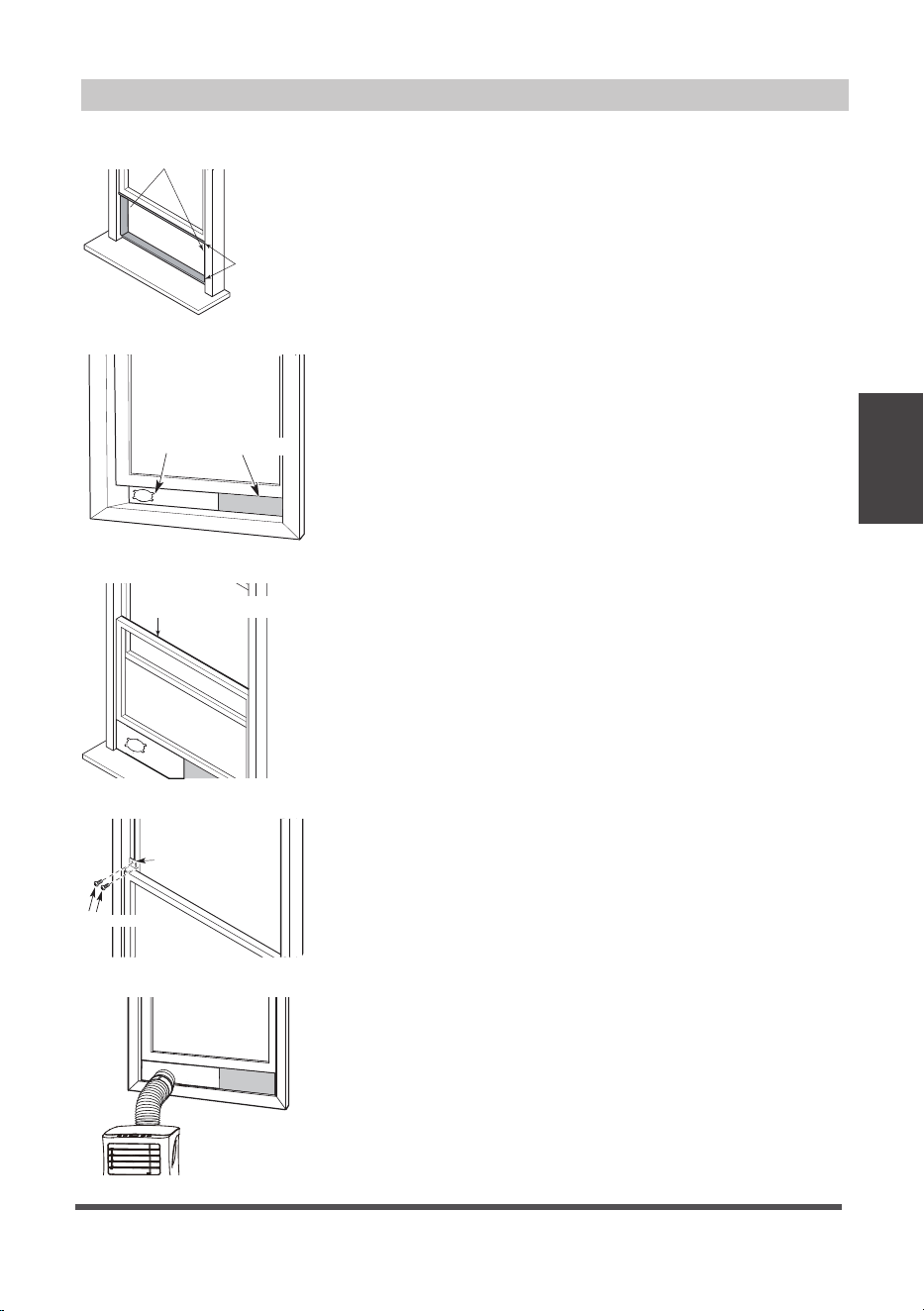
Window Installation Kit (cont.)
Type 1: Hung window installation
1. Cut the adhesive foam seal A and B strips to the
proper lengths, and attach them to the window sash
and frame as shown.
Foam seal B
(Adhesive type-shorter)
Foam
seal A
(Adhesive
type)
Window
slider A
Window
slider B
(if required)
Foam seal C
(Non-adhesive type)
Security Bracket
2 Screws
2. Insert the window slider assembly into the window
opening.
3. Cut the non-adhesive foam seal C strip to match the
width of the window. Insert the seal between the glass
and the window frame to prevent air and insects from
getting into the room.
4. If desired, install the security bracket with 2 screws as
shown.
5. Insert the window slider adaptor into the hole of the
window slider.
Installation
Instructions
Page 16
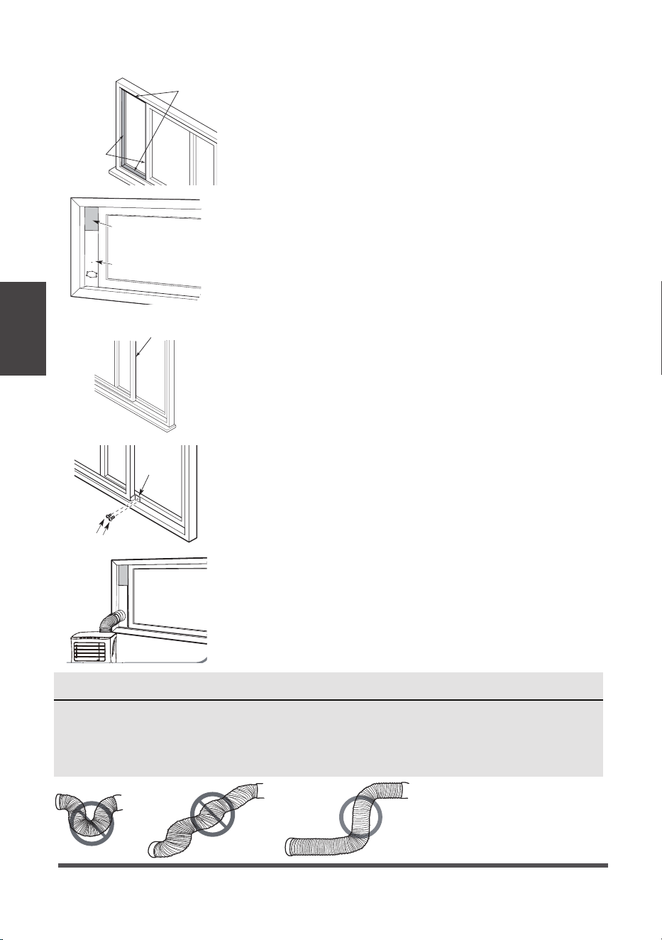
Type 2: Sliding window installation
1. Cut the adhesive foam seal A and B strips to the
proper lengths, and attach them to the window sash
and frame as shown.
Window slider A
Window slider B
(if required)
Foam seal B
(Adhesive
type-shorter)
Foam seal A
(Adhesive
type)
Foam seal C
(Non-adhesive type)
2 Screws
Security
Bracket
2. Insert the window slider assembly into the window
opening.
3. Cut the non-adhesive foam seal C strip to match the
window height. Insert the foam seal between the glass
and the window frame to prevent air and insects from
getting into the room.
4. If desired, install the security bracket with 2 screws
as shown.
5. Insert the window slider adaptor into the hole of the
window slider.
NOTE
To ensure proper functioning, DO NOT overextend or bend the hose. Make sure that
there is no obstacle around the air outlet of the exhaust hose (in the range of approx.
20 inches) in order for the exhaust system to work properly. All illustrations in this
manual are for explanation purposes only. Your air conditioner may be slightly
different than the illustrations shown here.
Care and
Cleaning
Page 17
Safety Precautions
Clean the Air Filter
Clean the Unit
Store the Unit When Not in Use
Maintenance Tips
• Be sure to clean the air filter every 2 weeks for
optimal performance.
• The water collection tray should be drained
immediately after P1 error occurs, and before
storage to prevent mold.
• In households with animals, you will have to
periodically wipe down the grill to prevent
blocked airflow due to animal hair.
• Always unplug the unit before cleaning or servicing.
• DO NOT use flammable liquids or chemicals to clean the unit.
• DO NOT wash the unit under running water. Doing so causes electrical danger.
• DO NOT operate the machine if the power supply was damaged during cleaning.
A damaged power cord must be replaced with a new cord from the manufacturer.
Clean the unit using a damp, lint-free cloth and mild detergent. Dry the unit with a dry,
lint-free cloth.
• Drain the unit’s water collection tray according to the instructions in the following section.
• Run the unit on FAN mode for 12 hours in a warm room to dry it and prevent mold.
• Turn off the unit and unplug it.
• Clean the air filter according to the instructions in the previous section. Reinstall the
clean, dry filter before storing.
• Remove the batteries from the remote control.
NOTE
Be sure to store the unit in a cool, dark place. Exposure to direct sunlight or extreme
heat can shorten the lifespan of the unit.
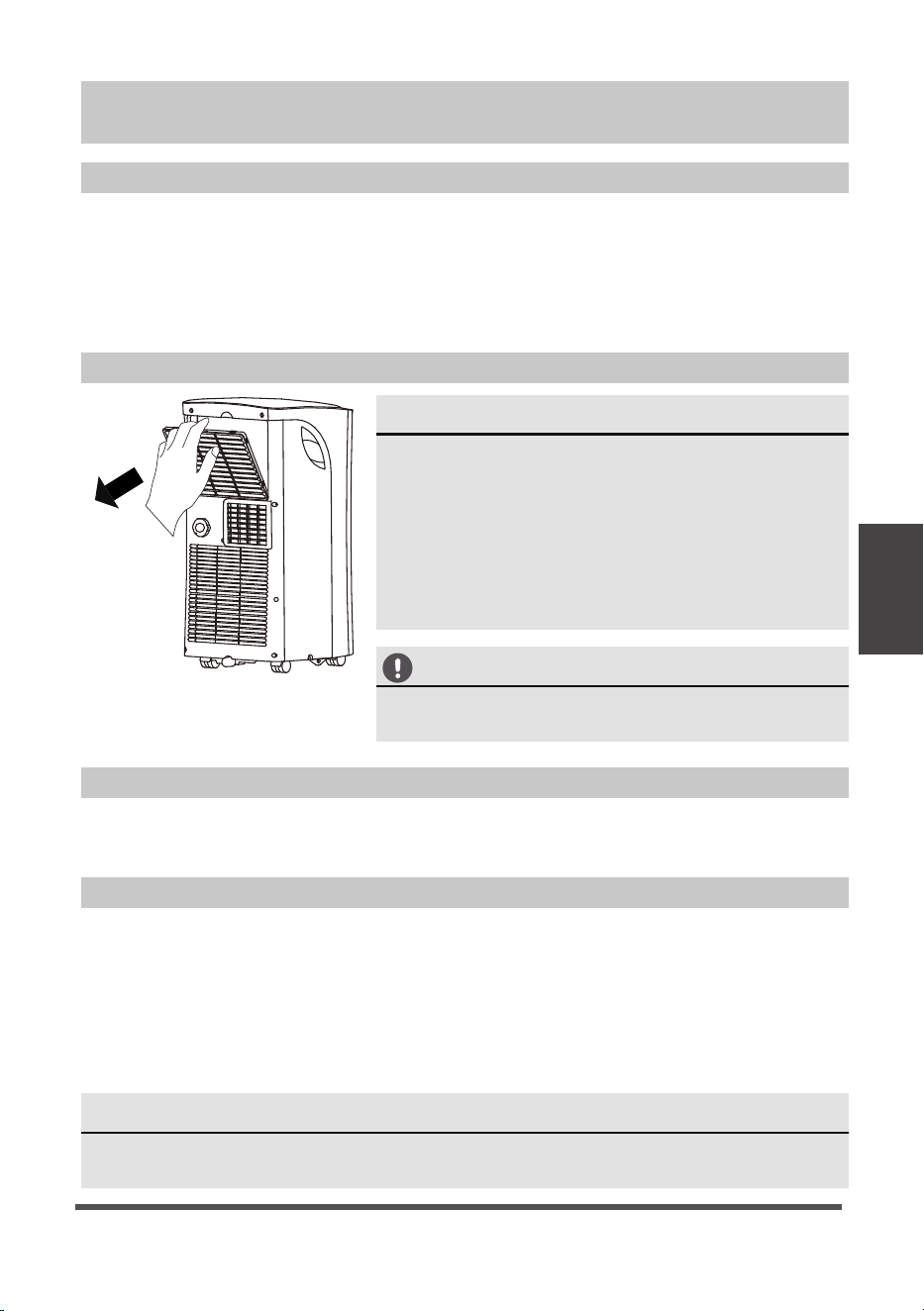
Remove the air filter
Air filter
(take out)
CAUTION
DO NOT operate the unit without fi lter because
dirt and lint will clog it and reduce performance.
Care and Cleaning
Troubleshooting
Tips
Page 18
Problem Possible Cause Troubleshooting
Unit does not
turn on when
pressing ON/
OFF button
P1 Error Code. The water collection tray is full.
Turn off the unit, drain the water
from the water collection tray
and restart the unit.
In COOL mode: room temperature
is lower than the set temperature.
Reset the temperature.
Unit does not
cool well
The air filter is blocked with dust
or animal hair.
Turn off the unit and clean the
filter according to instructions.
Exhaust hose is not connected or
is blocked.
Turn off the unit, disconnect the
hose, check for blockage and
reconnect the hose.
The unit is low on refrigerant. Call a service technician to
inspect the unit and top off
refrigerant.
Temperature setting is too high. Decrease the set temperature.
The windows and doors in the
room are open.
Make sure all windows and doors
are closed.
The room area is too large. Double-check the cooling area.
There are heat sources inside the
room.
Remove the heat sources if
possible.
The unit is
noisy and
vibrates too
much
The floor is not level. Place the unit on a flat, level
surface.
The air filter is blocked with dust
or animal hair.
Turn off the unit and clean the
filter according to instructions.
The unit makes
a gurgling
sound
This sound is caused by the flow
of refrigerant inside the unit
This is normal.
Malfunction Diagnosis
P
lease check the following troubleshooting methods before calling for service:
Troubleshooting Tips
Operating
Instructions
(With Remote)
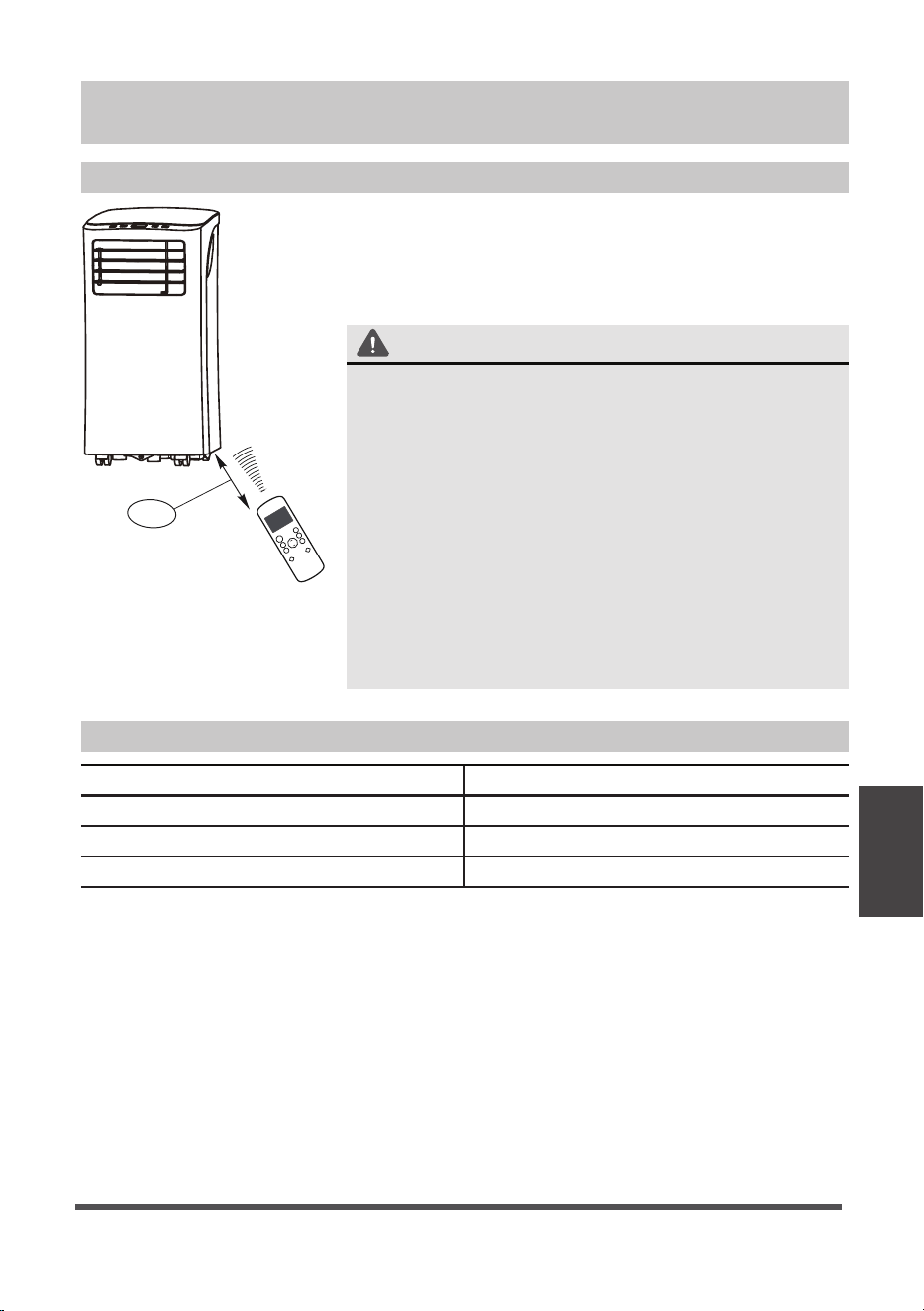
Using The Remote Control
Location of the remote controller
Use the remote controller within a distance of 8 meters
/ 26 feet from the appliance, pointing it towards the
receiver. Reception is confirmed by a beep.
CAUTION
• The air conditioner will not operate if curtains, doors
or other materials block the signals from the remote
controller to the indoor unit.
• Prevent any liquid from falling into the remote
controller. Do not expose the remote controller to
direct sunlight or heat.
• If the infrared signal receiver on the indoor unit is
exposed to direct sunlight, the air conditioner may
not function properly. Use curtains to prevent the
sunlight from falling on the receiver.
• If other electrical appliances react to the remote
controller, either move these appliances or call
customer support.
8m
TE
M
P
Remote Control Instructions
Remote Control Specifications
Model RG57H1(B)/BGCEU1-M
Rated voltage 3.0V (Dry batteries R03/LR03x2)
Signal receiving range
8 m (approx. 26 ft.)
Environment -5°C ~ 60°C (23°F ~ 140°F)
Page 19
Operating
Instructions
(With Remote)
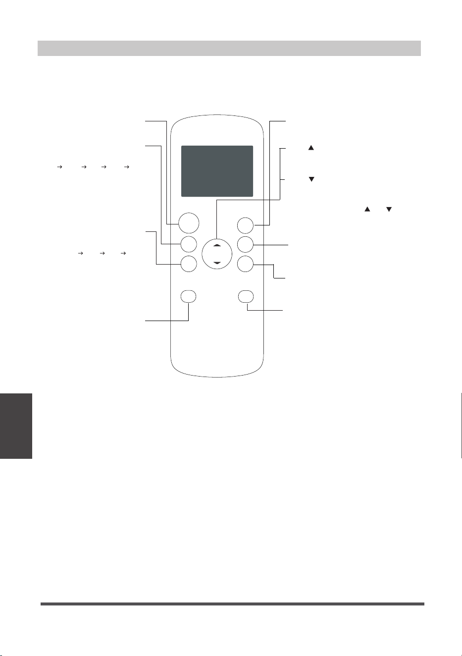
Function Buttons
Before you begin using your new air conditioner, make sure to familiarize yourself with
its remote control. The following is a brief introduction to the remote control itself. For
instructions on how to operate your air conditioner, refer to the Operating Instructions
section of this manual.
Page 20
O N /O F F
T E MP
SHORT
CUT
TIMER
ON
TIMER
OFF
MODE
FAN
LED
SLEEP
SHORT CUT
Sets and activates your favorite pre-settings.
ON/OFF
Turns the unit on or off.
TEMP
Increases temperature in 1° increments.
Max. Temperature 86 °F (30 °C).
TIMER ON
Sets timer to turn unit on (see How to Use
Basic Functions for instructions)
TIMER OFF
Sets timer to turn unit off (see How to Use
Basic Functions for instructions)
LED
Turns the AC’s LED display on and off.
SLEEP
Saves energy during
sleeping hours.
TEMP
Decreases temperature in 1° increments.
Min. Temperature 62 °F (17 °C).
NOTE: Pressing and hold and buttons
together for 3 seconds will alternate the
temperature display between the °C & °F scale.
FAN SPEED
Selects fan speeds in the
following order:
AUTO LOW MED HIGH
MODE
Scrolls through operation modes
as follows:
AUTO COOL DRY HEAT FAN
NOTE:
Please do not select HEAT mode
if the machine you purchased is
cool-only type. Heat mode is not
supported by the cool-only models.
Operating
Instructions
(With Remote)
Not sure what a function does?
Refer to the Operating Instructions section of this manual for detailed descriptions of the
functions available using the remote.
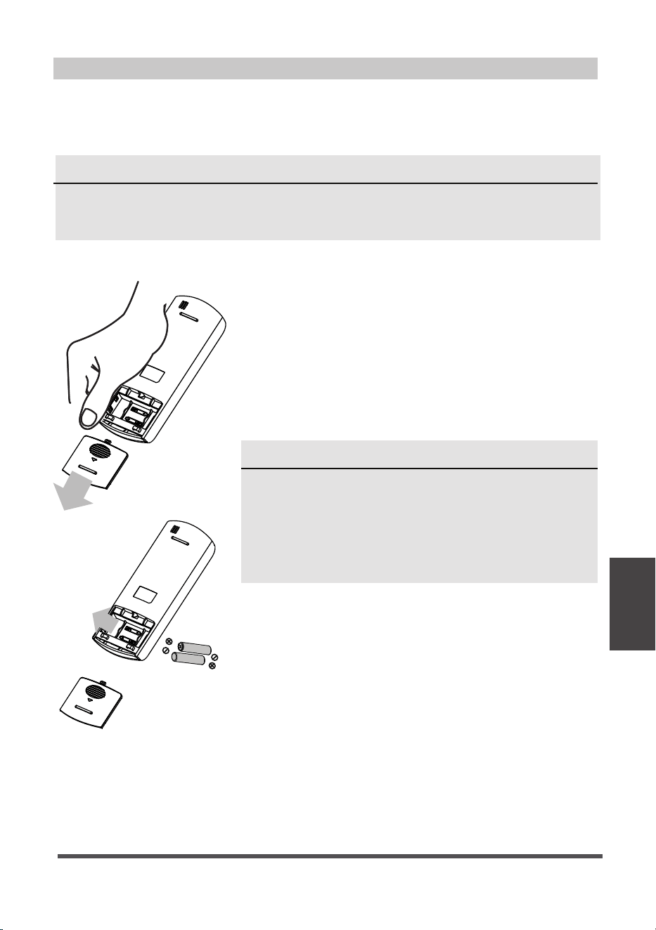
INSERTING AND REPLACING BATTERIES
Your air conditioning unit comes with two AAA batteries.
Insert the batteries in the remote control before use.
1. Slide the back cover of the remote control downward,
exposing the battery compartment.
2. Insert the batteries, paying attention to align the (+)
and (-) ends of the batteries with the symbols inside
the battery compartment.
3. Slide the battery cover back into place.
BATTERY DISPOSAL
Ensure used batteries are disposed of properly.
TIPS FOR USING REMOTE CONTROL
•
The remote control must be used within 26 feet/
8 meters of the unit.
•
The unit will beep when it receives a signal from
the remote.
•
Curtains, other materials, and direct sunlight can
inter
fere with the IR signal receiver.
•
In order to properly transmit a command, the ON/
OFF indicator must be illuminated on the remote’s
display. (See the Remote LED Screen Indicators
section for more information.)
Handling the Remote Control
Notice
Button designs on your unit may differ slightly from the examples below.
If the unit does not have a specific function, using that function’s button on the
remote control will have no eff.
BATTERY NOTES
For optimum product performance:
• Do not mix old and new batteries, or batteries of
different types.
• Do not leave batteries in the remote control if you
don’t plan on using the device for more than 2
months.
Page 21
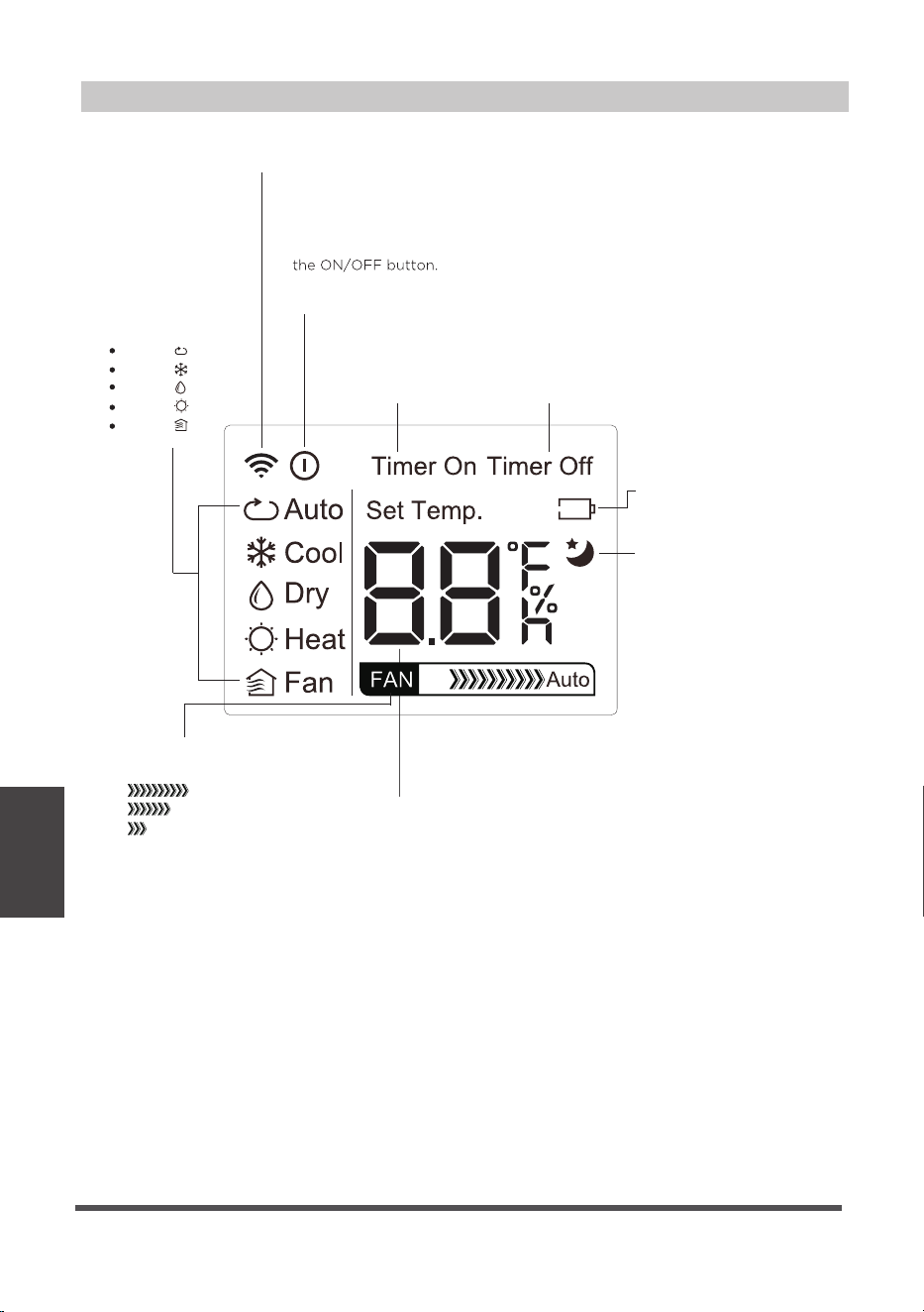
Remote LED Screen Indicators
AUTO
COOL
DRY
HEAT
FAN
Transmission Indicator
Lights up when remote sends signal to unit
MODE display
Displays the current
mode, including:
TIMER ON display
Displays when
TIMER ON is set
TIMER OFF display
Displays when
TIMER OFF is set
Battery display
Low battery detection
SLEEP display
Displays when SLEEP
function is activated
FAN SPEED display
Displays selected FAN SPEED:
HIGH
MED
LOW
This display is blank when
set to AUTO speed.
Temperature/Timer display
Displays the set temperature by default, or timer setting
when using TIMER ON/OFF functions:
-Temperature range 62°F - 86 °F (17 °C - 30 °C)
- Timer setting range: 0-24 hours
This display is blank when operating in FAN mode.
ON/OFF Indicator
Appears when the remote is enabled and can send a signal to the unit.
If you would like to turn the remote off without affecting the unit,
point the remote away from the unit and press the ON/OFF button.
To turn the remote on, point the remote away from the unit and press
The unit will not receive commands from the remote if this indicator is
not illuminated.
Operating
Instructions
(With Remote)
22 egaP

Basic Functions
1
3
2
O N /O F F
T E MP
SHORT
CUT
TIMER
ON
TIMER
OFF
MODE
FAN
SLEEP
LED
SETTING THE DESIRED TEMPERATURE
CHANGING THE MODE
1. The operating temperature range for this unit is 62°F-86°F
(17-30°C). You can increase or decrease the set temperature
in 1°F (1°C) increments by pressing the ↑ or ↓buttons.
1. To change the operating mode, press the MODE button
until the desired mode appears on the remote’s display.
2. Set the desired temperature.
NOTICE
If the unit does not change when the button is pressed,
check that the ON/OFF indicator is illuminated. If it is not,
point the remote at the unit and press the ON/OFF button.
Operating
Instructions
(With Remote)
Page 23
NOTICE
If the unit does not change when the button is pressed,
check that the ON/OFF indicator is illuminated. If it is not,
point the remote at the unit and press the ON/OFF button.
Changing the Fan Speed
1. To change the fan speed, press the FAN button until the
desired fan speed appears on the remote’s display.
1
2
3
O N /O F F
T E MP
SHORT
CUT
TIMER
ON
TIMER
OFF
MODE
FAN
SLEEP
LED
Timer Functions
Your air conditioning unit has two timer-related functions:
TIMER ON - sets the amount of time after which the unit
will automatically turn on.
TIMER OFF - sets the amount of time after which the unit
will automatically turn off.
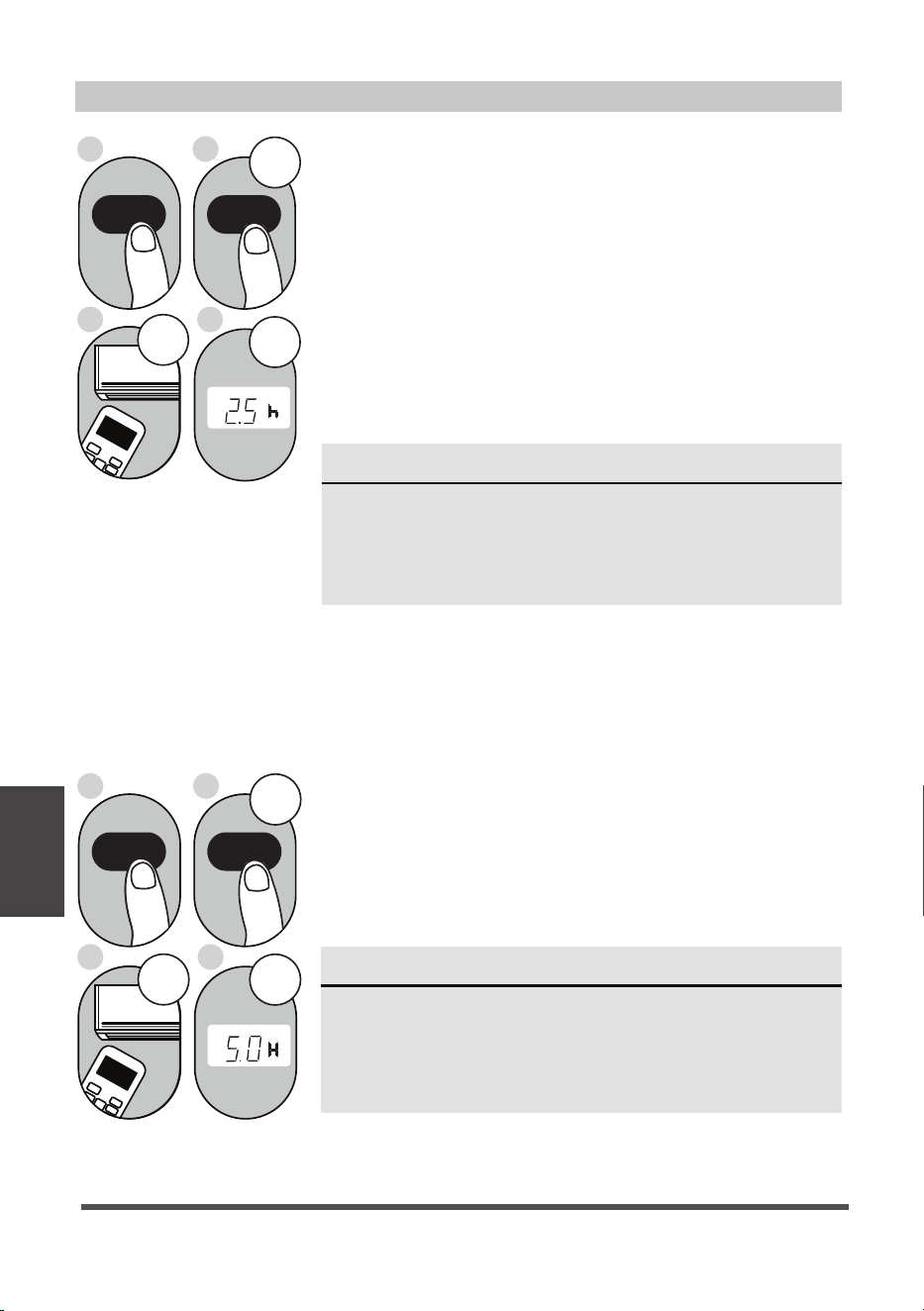
TIMER ON function
The TIMER ON function allows you to set a period of time
after which the unit will automatically turn on, such as when
you come home from work.
1. Press the TIMER ON button. By default, the last time
period that you set and an “h” (indicating hours) will
appear on the display.
2sec
ON/OFF
MODE
FAN
SHORT
CUT
TIMER ON
TIMER OF
F
TEMP
S
L
E
EP
1sec
x5
1
3
2
4
TIMER ON TIMER ON
Example: Setting unit to
turn on after 2.5 hours.
2sec
x10
ON/OFF
MODE
F
AN
SHORT
CUT
TIMER ON
TIMER OF
F
TEMP
S
LEEP
1sec
1
3
2
4
TIMER OFF
TIMER OFF
NOTICE
This number indicates the amount of time after the
current time after which you want the unit to turn on.
For example, if you set TIMER ON for 2 hours, “2.0h“
will appear on the screen, and the unit will turn on
after 2 hours.
NOTICE
This number indicates the amount of time after the
current time after which you want the unit to turn off.
For example, if you set TIMER OFF for 2 hours, “2.0h“
will appear on the screen, and the unit will turn off
after 2 hours.
2. Press the TIMER ON button repeatedly to set the time
that you want the unit to turn on.
3. Wait 2 seconds, then the TIMER ON function will be
activated. The digital display on your remote control will
then return to the temperature display.
TIMER OFF function
The TIMER OFF function allows you to set a period of time
after which the unit will automatically turn off, such as when
you wake up.
1. Press the TIMER OFF button. By default, the last time
period that you set and an “h” (indicating hours) will
appear on the display.
2. Press the TIMER OFF button repeatedly to set the time
that you want the unit to turn off.
Example: Setting unit to
turn off after 5 hours.
Operating
Instructions
(With Remote)
Page 24
NOTE
When setting the TIMER ON or TIMER OFF functions,
up to 10 hours, the time will increase in 30 minute
increments with each press. After 10 hours and up to
24, it will increase in 1 hour increments. The timer will
revert to zero after 24 hours.
You can turn off either function by setting the timer to
“0.0h“.
3. Wait 2 seconds, then the TIMER OFF function will be
activated. The digital display on your remote control will
then return to the temperature display.
O N /O F F
T E M P
SHORT
CUT
TIMER
ON
TIMER
OFF
MODE
FAN
SLEEP
LED
T i m e r on
Continue
to press
TIMER ON
or
TIMER OFF
until desired
time is
reached.
ON/OFF
M
O
D
E
SHORT
CU
T
TIMER ON
TE
M
P
sec
4
ON/OFF
M
O
D
E
SHORT
C
UT
TIMER ON
TEMP
sec
8
1
TIMER ON
X12
2
TIMER ON
5
TIMER OFF
X16
6
TIMER OFF
3
7
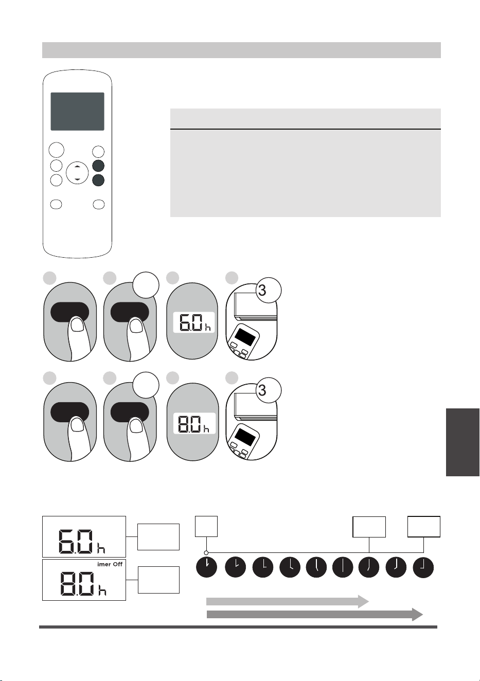
Setting both TIMER ON and
TIMER OFF at the same time
Keep in mind that the time
periods you set for both
functions refer to hours after
the current time.
For example, say that the
current time is 1:00 PM, and
you want the unit to turn on
automatically at 7:00 PM and
want it to operate for 2 hours,
then automatically turn off at
9:00 PM.
Do the following (side figure):
Example: Setting the unit to turn on after 6 hours, operate for 2 hours, then turn off
(see the figure below)
Timer On
T
Timer is set
To turn ON
6 hours from
current time
Timer is set
To turn OFF
8 hours from
current time
Current
Time 1PM
2PM 3PM
4PM 5PM
6PM 7PM 8PM 9PM
Unit turns
ON
Unit turns
OFF
6 hours later
8 hours later
Timer
Starts
Your remote display
Operating
Instructions
(With Remote)
Timer Functions (cont.)
Page 25
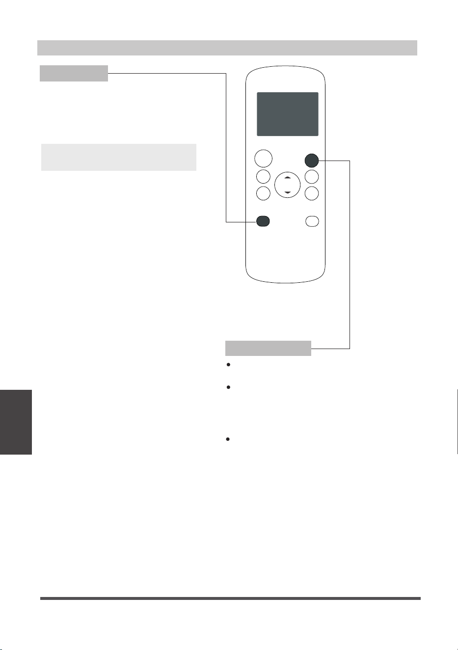
Advanced Functions
SHORTCUT Function
Note:
O N /O F F
T E MP
SHORT
CUT
TIMER
ON
TIMER
OFF
MODE
FAN
LED
SLEE P
SLEEP Function
The SLEEP function is used to decrease
energy use while you sleep (and don’t need
the same temperature settings to stay
comfortable).
Used to restore the current settings or resume
previous settings.
Push this button when remote controller is on,
the system will automatically revert back to the
previous settings including operating mode,
setting temperature, fan speed level and sleep
feature (if activated).
By pressing for more than 2 seconds, the
system will automatically store the current
operation settings including operating mode,
setting temperature, fan speed level and sleep
feature (if activated).
The SLEEP function is not
available in FAN or DRY mode.
Operating
Instructions
(With Remote)
Page 26

Warranty
Air Conditioner Limited Warranty
Your product is protected by this Limited Warranty:
Warranty service must be obtained from Midea Consumer Services or an authorized Midea servicer.
Warranty
• One year limited warranty from original purchase date.
Midea, through its authorized servicers will:
• Pay all costs for repairing or replacing parts of this appliance which prove to be defective in materials or
workmanship.
Consumer will be responsible for:
• Diagnostics, removal, transportation and reinstallation cost required because of service.
• Costs of service calls that are a result of items listed under NORMAL RESPONSIBILITIES OF THE CONSUMER**
Midea replacement parts shall be used and will be warranted only for the original warranty.
NORMAL RESPONSIBILITIES OF THE CONSUMER**
This warranty applies only to products in ordinary household use, and the consumer is responsible for the items
listed below:
1. Proper use of the appliance in accordance with instructions provided with the product.
2. Routine maintenance and cleaning necessary to keep the good working condition.
3. Proper installation by an authorized service professional in accordance with instructions provided with the
appliance and in accordance with all local plumbing, electrical and/or gas codes.
4. Proper connection to a grounded power supply of sufficient voltage, replacement of blown fuses, repair of loose
connections or defects in house wiring.
5. Expenses for making the appliance accessible for servicing.
6. Damages to finish after installation.
EXCLUSIONS
This warranty does not cover the following:
1) Failure caused by damage to the unit while in your possession (other than damage caused by defect or
malfunction), by its improper installation, or by unreasonable use of the unit, including without limitation, failure to
provide reasonable and necessary maintenance or to follow the written installation and Operating Instructions.
2) Damages caused by services performed by persons other than authorized Midea costumer service; or external
causes such as abuse, misuse, inadequate power supply or acts of God.
3) If the unit is put to commercial, business, rental, or other use or application other than for consumer use, we make
no warranties, express or implied, including but not limited to, any implied warranty of merchantability or fitness
for use or purpose.
4) Products without original serial numbers or products that have serial numbers which have been altered or cannot
be readily determined.
NOTE: Some states do not allow the exclusions or limitation of incidental or consequential damages. So this
limitation or exclusion may not apply to you.
IF YOU NEED SERVICE
Keep your bill of sale, delivery slip, or some other appropriate payment Record.
The date on the bill establishes the warranty period, should service be required.
If service is performed, its your best interest to obtain and keep all receipts.
This written warranty gives you specific legal rights. You may also have other rights that vary from state to state.
Service under this warranty must be obtained by following these steps, in order:
1) Contact Midea Consumer Services or an authorized Midea services at 1 866 646 4332.
2) If there is a question as to where to obtain service, contact our consumer relations Department.
Warranty
72 egaP

How to Stay Cool with a New Portable Air Conditioner
What should I look for first when purchasing a portable air conditioner?
Why is the cooling capacity lower on newer models than on older units?
Because of a new federal test procedure for Portable Air Conditioners, you may
notice that the cooling capacity claims on portable air conditioner packaging are
significantly lower than that of models produced prior to 2017. This is due to
changes in the test procedure, not to the portable air conditioners themselves.
The right air conditioner helps you cool a room efficiently. An undersized unit
won't cool adequately while one that's too large will not remove enough humidity,
leaving the air feeling damp. To find the proper air conditioner, determine the
square footage of the room you want to cool by multiplying the room length by
its width. You also need to know the air conditioner's BTU (British Thermal Unit)
rating, which indicates the amount of heat it can remove from a room. A higher
number means more cooling power for a larger room. (Be sure you are
comparing only newer models to each other- older models may appear to have
a higher capacity, but are actually the same). Be sure to “size up” if your portable
air conditioner will be placed in a very sunny room, in a kitchen, or in a room with
high ceilings. After you’ve found the right cooling capacity or your room, you can
look at other features.
Federal regulations require manufacturers to calculate cooling capacity based
on a specific test procedure. Models manufactured before 2017 were tested
under a different procedure and cooling capacity is measured differently than
in prior years’ models. So, while the BTUs may be lower, the actual cooling
capacity of the air conditioners has not changed.
What is SACC ?
SACC is the representative value of Seasonally Adjusted Cooling Capacity, in
Btu/h, as determined in accordance with the DOE test procedure at title 10
Code of Federal Regulations (CFR) 430, subpart B, appendix CC and applicable
sampling plans.