Loading ...
Loading ...
Loading ...
Connect Drain Hose to Drain
Receptacle
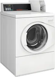
Remove the drain hose from its shipping position on the rear of
the washer by removing the shipping tape.
IMPORTANT: Drain receptacle must be capable of han-
dling a minimum of 1-3/8 inch [35 mm] outside diame-
ter drain hose.
Drain Flow Rate
Drain Height
Flow Rate
gallons per minute [lit-
ers per minute]
3 ft. [0.9 m] 8.6 [32.7]
5 ft. [1.5 m] 6.8 [25.9]
6 ft. [1.8 m] 6.0 [22.7]
7 ft. [2.1 m] 5.1 [19.5]
8 ft. [2.4 m] 4.0 [15.2]
FLW2348_SVG
1
1. Shipping Tape
Figure 9
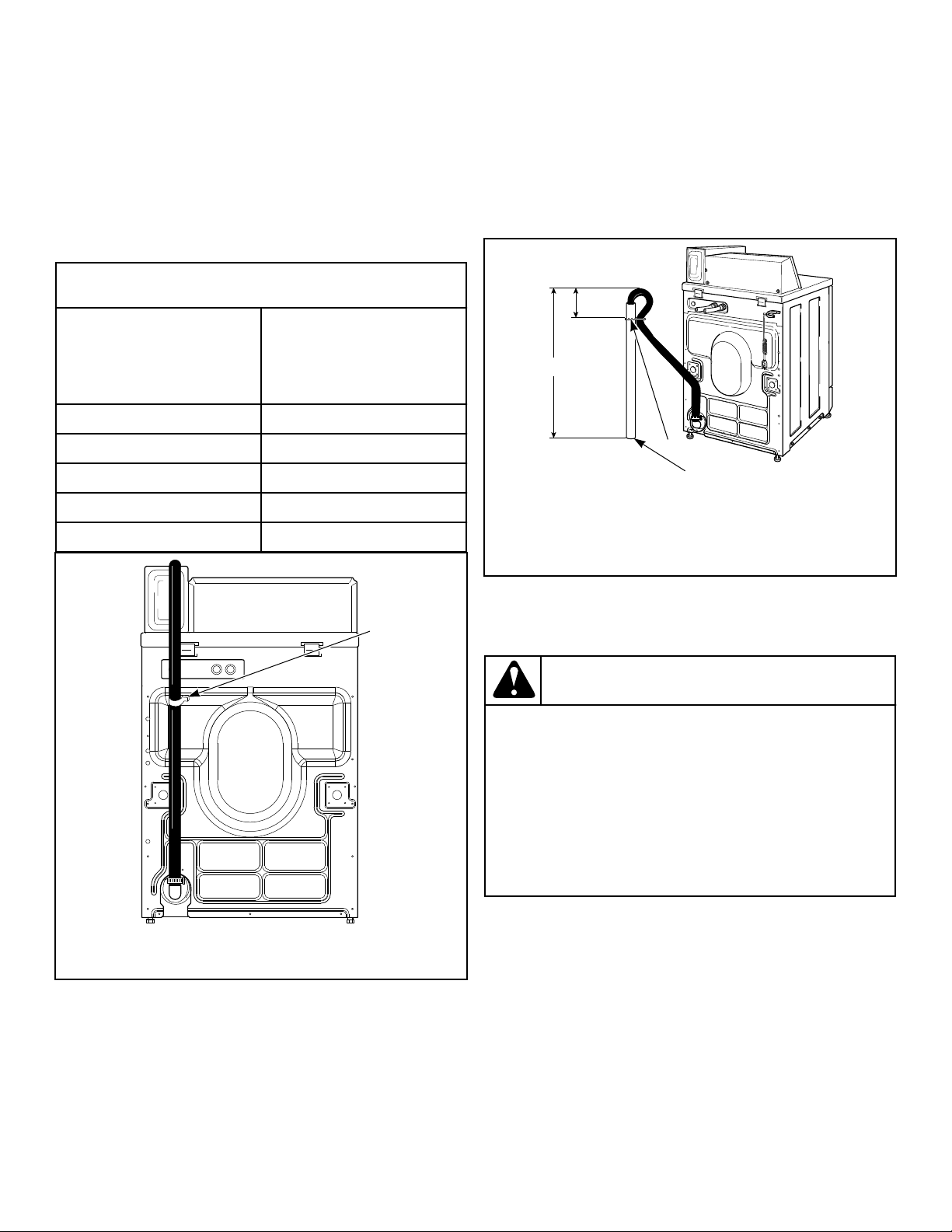
Standpipe Installation
1. Place the drain hose into the standpipe.
2. Remove the beaded tie-down strap from accessories bag and
place around standpipe and drain hose and tighten strap to
hold hose to standpipe. Refer to Figure 10 . This will prevent
the drain hose from dislodging from drain receptacle during
use.
3. If hose does not fit securely in standpipe because it is too
long:
a. Remove hose clamp attaching it to washer.
b. Cut hose to desired length.
c. Reattach hose and hose clamp.
FLW2349N_SVG
2
3
1
1. 24 to 36 in. [610 to 914 mm] Recommended Height
2. Beaded strap from accessory bag
3. Standpipe 2 in. [51 mm] or 1-1/2 in. [40 mm]
Figure 10
Position and Level the Washer
WARNING
Washers elevated above floor level must be anch-
ored to that elevated surface, base or platform. The
material used to elevate the washer should also be
anchored to the floor to ensure that the washer will
not walk or that the washer can not be physically
pulled, tipped or slid from its installed position. Fail-
ure to do so may result in conditions which can pro-
duce serious injury, death and/or property damage.
W306
1. Position unit so it has sufficient clearance for installation and
servicing.
NOTE: Use of the dispenser drawer or washer door
as a handle in the transportation of the washer may
cause damage to the dispenser or door.
2. Place unit in position on a solid, sturdy and level floor. Instal-
ling the unit on any type of carpeting, soft tile or other weakly
supported structures is not recommended.
3. Place a level on the raised portion of cabinet top and check if
the unit is level from side to side and front to back.
Installation
©
Copyright, Alliance Laundry Systems LLC -
DO NOT COPY or TRANSMIT
12 Part No. 805411R2
Loading ...
Loading ...
Loading ...