Loading ...
Loading ...
Loading ...
5
Voltage Measurements
The line voltage measurement should be 120VAC +/-10% fluctuation at 60 Hz. The peak volt-
age should be 1.414 times the rms line voltage reading for a clean sine waveform. Ground-to-
neutral voltage should be less than 2 VAC. In a single-phase circuit, a higher ground-neutral
voltage indicates excessive current leakage between the neutral and ground conductors. In a 3-
phase circuit with a shared neutral, a high ground-neutral voltage could indicate an unbalanced
load between the three phases or harmonic distortion on the shared neutral. Excessive ground-
neutral voltage may result in inconsistent or intermittent equipment performance.
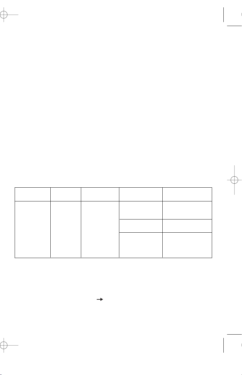
Troubleshooting Tips for Voltage Issues
Measurement Expected Problem Possible Possible
Result Causes Solutions
Too much load on Redistribute loads
the load on circuit. on the circuit.
High resistance Locate high resistance
connection within connection/device and
the circuit or at repair/replace.
the panel.
Supply voltage Consult power
too high/low. company.
Current leaking Identify source of leakage:
from neutral to multiple bonding points,
ground. equipment or devices.
Unbalanced 3- Check load balance
phase system. and redistribute load.
Triplen harmonics Oversize neutral to
returning on impedance. Reduce
neutral in 3-phase harmonic effect via
system. filter or other methods.
Supply voltage Consult power
too high/low. company.
High Peak Loads Evaluate number of
on line caused by electronic devices on
electronic equipment circuit and redistribute
on line. if necessary.
Supply frequency Consult power
too high/low. company.
Voltage Drop (V
D
) Measurements
The SureTest measures the line voltage, applies a load on the circuit, measures the loaded
voltage, then calculates the voltage drop. Results are displayed for 12A, 15A, and 20A
loads. The National Electrical Code recommends 5% as the maximum voltage drop for
branch circuits for reasonable efficiency (NEC article 210-19. FPN 4). And, the voltage
under load (V
L
) should not drop below 108VAC for reliable equipment operation.
A good branch circuit should start out with less than 5% voltage drop at the furthest recep-
tacle from the panel at the end of the cable run. Then, each receptacle tested in sequence
towards the panel should show a steady decrease in voltage drop. If the voltage drop is
above 5% and does not noticeably decrease as you get closer to the first device on the cir-
cuit, then the problem is between the first device and the panel. Visually check the termina-
tions at the first device, the wiring between the device and the panel, and the circuit breaker
connections. High resistance points can usually be identified as hot spots using an infrared
thermometer or by measuring the voltage across the breaker. If the voltage drop exceeds
5% but noticeably decreases as you nearer the panel, the circuit may have undersized wire,
too long of a cable run, or too much current on the circuit. Check the wire to ensure that it
is sized per code and measure the current on the branch circuit. If a voltage drop reading
changes significantly from one receptacle to the next, then the problem is a high impedance
point at or between two receptacles. It is usually located at a termination point, such as a
bad splice or loose wire connection, but it might also be a bad receptacle.
Troubleshooting Tips for Voltage Drop
Measurement Expected Problem Possible Possible
Result Causes Solutions
Too much Redistribute the
load on load on
the circuit. the circuit.
Undersized wire for Check code requirements
length of run. and re-wire if necessary.
High resistance Locate high
connection within resistance connection/
the circuit or at device and
the panel. repair/replace.
ASCC Measurement
The SureTest calculates the Available Short-Circuit Current (ASCC) that the branch circuit
can deliver through the breaker during a bolted fault (dead-short) condition.
The ASCC is calculated by dividing the line voltage by the circuit’s line impedance (hot +
neutral). Depressing the side arrow ( ) displays the worst-case scenario where all three
conductors (hot, neutral, ground) are shorted together -- the neutral and ground provide a
lower impedance via a parallel return path. Note that this second test will trip a GFCI. See
the following equations for clarification.
Line Voltage
120VAC
220VAC
Neutral-Ground
Voltage
Peak Voltage
120VAC
220VAC
Frequency
108-132VAC
198-242VAC
<2VAC
Voltage
153-185VAC
280-342VAC
60HZ
High/low
High G-N
>2VAC
High/low
peak voltage
High/low
frequency
Voltage Drop <5%
High Voltage
Drop
WARNING: Do not exceed the unit’s maximum voltage rating of 250VAC.
6
ND 5481-4 61-164 165 Ins 11/21/06 1:28 PM Page 5
Loading ...
Loading ...
Loading ...