M
UL
TI-ZONE
DUCTLESS INVERTER
SPLIT AIR CONDITIONER
WITH HEAT PUMP
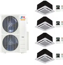
CASSETTE TYPE
USER’S MANUAL
INDOOR UNIT
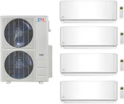
SOPHIA
IMPORTANT NOTE:
This manual describes the installation
and usage of dierent types of multi zone
air conditioner indoor units. Please, refer to
the corresponding part of the manual.
•
Read this manual carefully before
installing or operating your new air
conditioning unit. Make sure to save
this manual for future reference.
This manual only describes the installation of
outdoor unit. When installing the indoor unit,
refer to the installation manual of indoor unit.
•
•
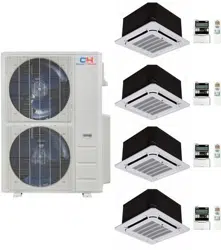
Models:
CH-09MSPHCT-230VI
CH-12MSPHCT-230VI
CH-18MSPHCT-230VI
CH-24MSPHCT-230VI

CONTENT
IMPORTANT SAFETY INFORMATION---------------------------------------------------------------------1
HINTS FOR ECONOMICAL OPERATION-----------------------------------------------------------------2
PARTS NAMES----------------------------------------------------------------------------------------------------2
MANUAL OPERATION-----------------------------------------------------------------------------------------14
ADJUSTING AIR FLOW DIRECTION-----------------------------------------------------------------------15
MAINTENANCE-------------------------------------------------------------------------------------------------16
AIR CONDITIONER OPERATIONS AND PERFORMANCE-------------------------------------------18
INSTALLATION--------------------------------------------------------------------------------------------------19
TROUBLES AND CAUSES-----------------------------------------------------------------------------------20
TROUBLES AND CAUSES(CONCERNING REMOTE CONTROLLER)---------------------------20
Danger
No
Household
Drain
Cleaner
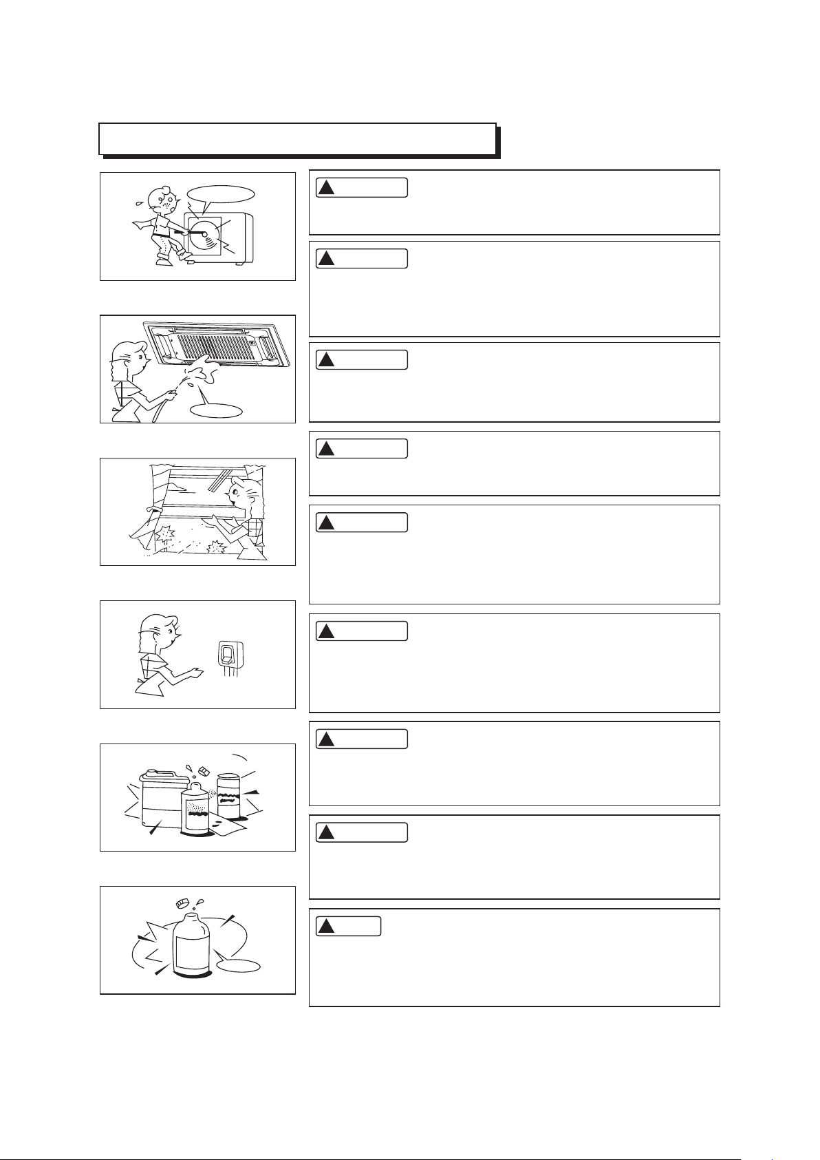
IMPORTANT SAFETY INFORMATION
Do not attempt to install this unit by yourself. This unit requires
installation by qualified persons.
Do not use caustic household drain cleaners in the unit. Drain
cleaners can quickly destroy the unit components (drain pan and
heat exchanger coil etc).
CAUTION
CAUTION
NOTE
DANGER
DANGER
WARNING
WARNING
WARNING
Do not attempt to service the unit yourself. This unit has no user
serviceable components. Opening or removing the cover will
expose you to dangerous voltage. Tuning off the power supply will
not prevent potential electric shock.
To avoid the risk of serious electrical shock, Never sprinkle or
spill water or liquids on unit.
Ventilate the room regularly while the air conditioner is in use,
especially if there is also a gas appliance in use in this room,
Failure to follow these directions may result in a loss of oxygen
in the room.
To prevent electric shock, turn off the power or disconnect the
power supply plug before beginning any cleaning or other routine
maintenance. Follow the directions for cleaning in the Owner's
Manual.
1
!
!
!
!
!
!
!
!
!
No
Thinner
DANGER
Never put hands or objects into the Air Outlet of indoor or outdoor
units. These units are installed with a fan running at high speed.
To touch the moving fan will cause serious injury.
Do not use liquid cleaners or aerosol cleaners, use a soft and dry
cloth for cleaning the unit. To avoid electric shock, never attempt
to clean the units by sprinkling water.
For proper performance, operate the unit in temperature and
humidity ranges indicated in this owner's manual. If the unit is
operated beyond these conditions, it may cause malfunctions
of the unit or dew dripping from the unit.
HINTS FOR ECONOMICAL OPERATION
The following should be noticed to ensure an economical operation. (Refer to corresponding chapter
for details)
Adjust the air flow direction properly to avoid winding toward your body.
Adjust the room temperature properly to get a comfortable situation and to avoid supercooling and
superheat.
In cooling, close the curtains to avoid direct sunlight.
To keep cool or warm air in the room, never open doors or windows more often than necessary.
Set the timer for the desired operating time.
Never put obstructions near the air outlet or the air inlet. Or it will cause lower efficiency, even a
sudden stop.
If you don't plan to use the unit for a long time, please disconnect power and remove the batteries
from the remote controller. When the power switch is connected, some energy will be consumed,
even if the air conditioner isn't in operation. So please disconnect the power to save energy. And
please switch the power on 12 hours before you restart the unit to ensure a smooth operation.
A clogged air filter will reduce cooling or heating efficiency, please clean it once two weeks.
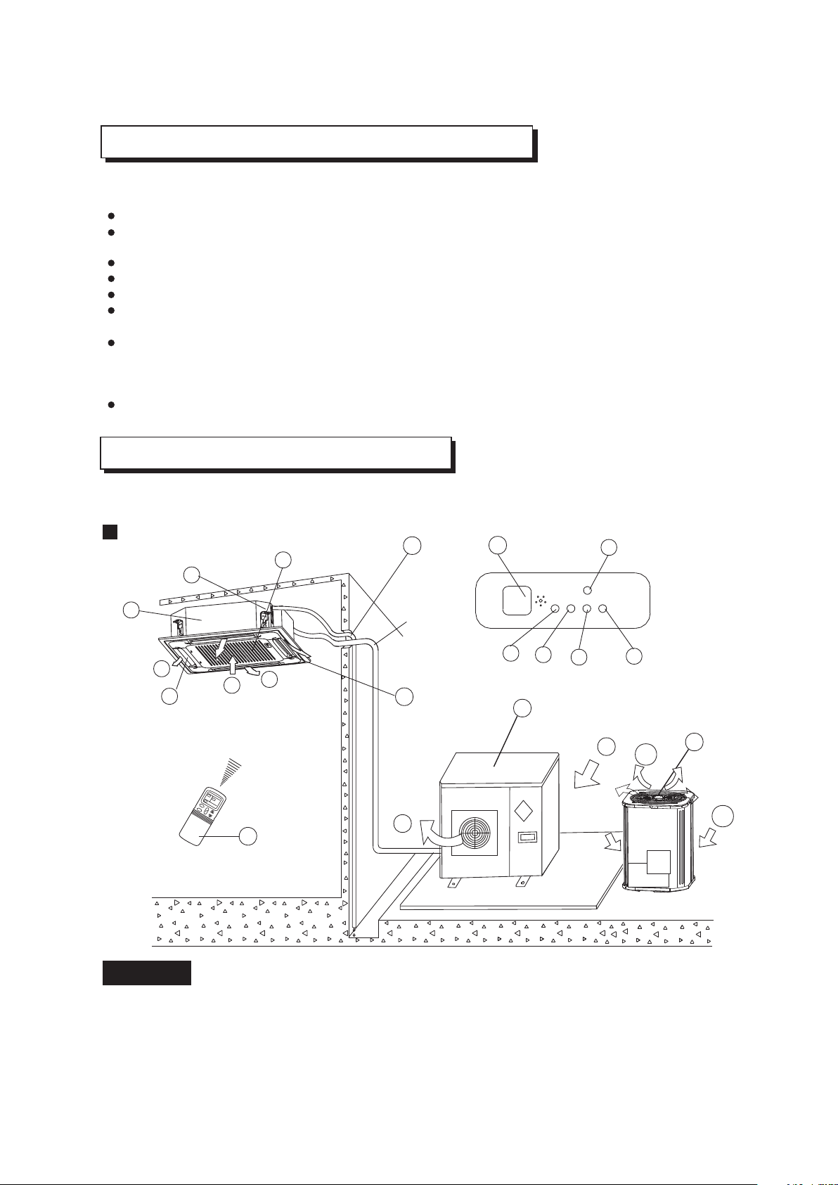
PARTS NAMES
f
b
d
e
i
m
n
l
p
o
c
q
a
j
k
e
g
d
e
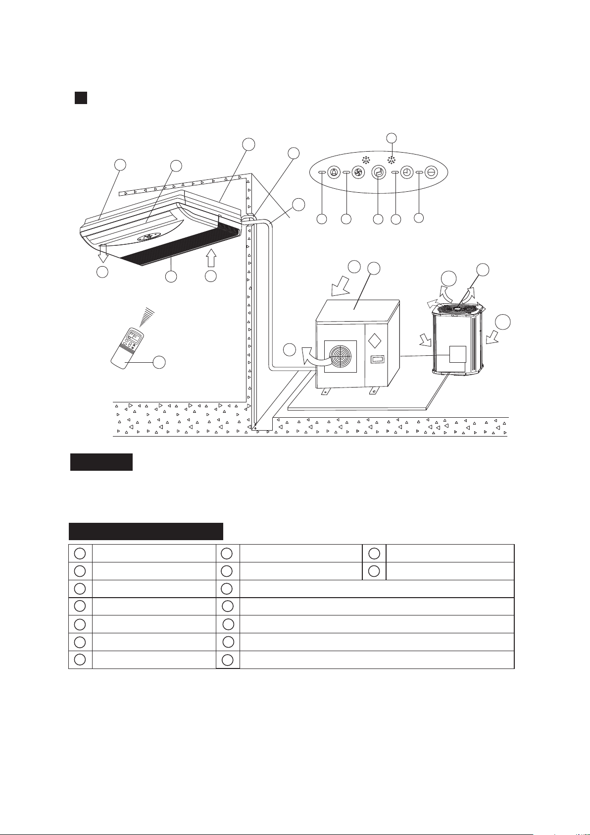
Display Panel
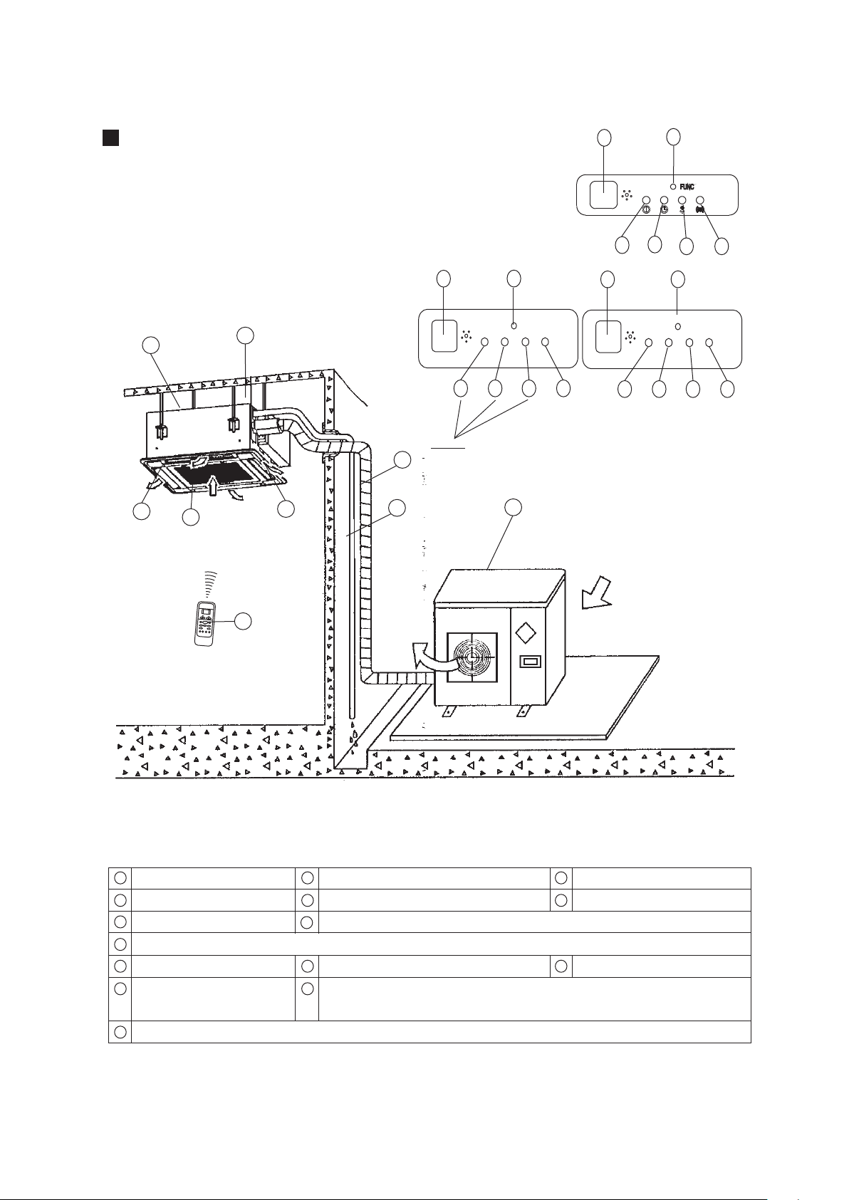
The air conditioner consists of the indoor unit, the outdoor unit, the connecting pipe and the remote
controller.
Cassette Type
NOTICE!
This chart is based on 24000Btu/h type. So, a few differences may exist on the outlook and functions
from yours.
2
b
d
e
or
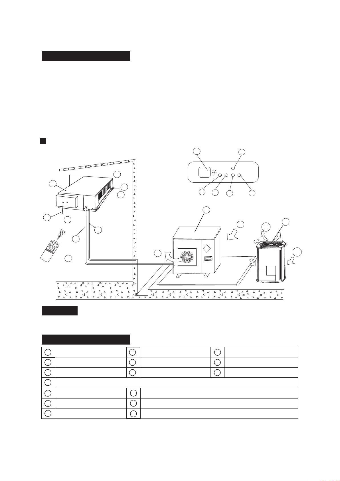
a) indoor unit b) outdoor unit
c) remote controller d) air-in
e) air-out f ) air outlet
g) air flow louver (at air outlet) h) connecting pipe
i ) drain hose j ) air inlet (with air filter in it)
k) drain pump (drain water from indoor unit) l ) infrared signal receiver
m) temporary button n) operation lamp
o) timer indicator
p) PRE-DEF indicator (cooling and heating type) or fan only indicator (cooling only type)
q) alarm indicator
NAMES AND FUNCTIONS
NAMES AND FUNCTIONS
h
b
d
e
i
m
n
l
p
o
b
c
f
a
d
e
g
h
i
j
k
m
o
p
l
n
c
k
f
d
j
a
k
g
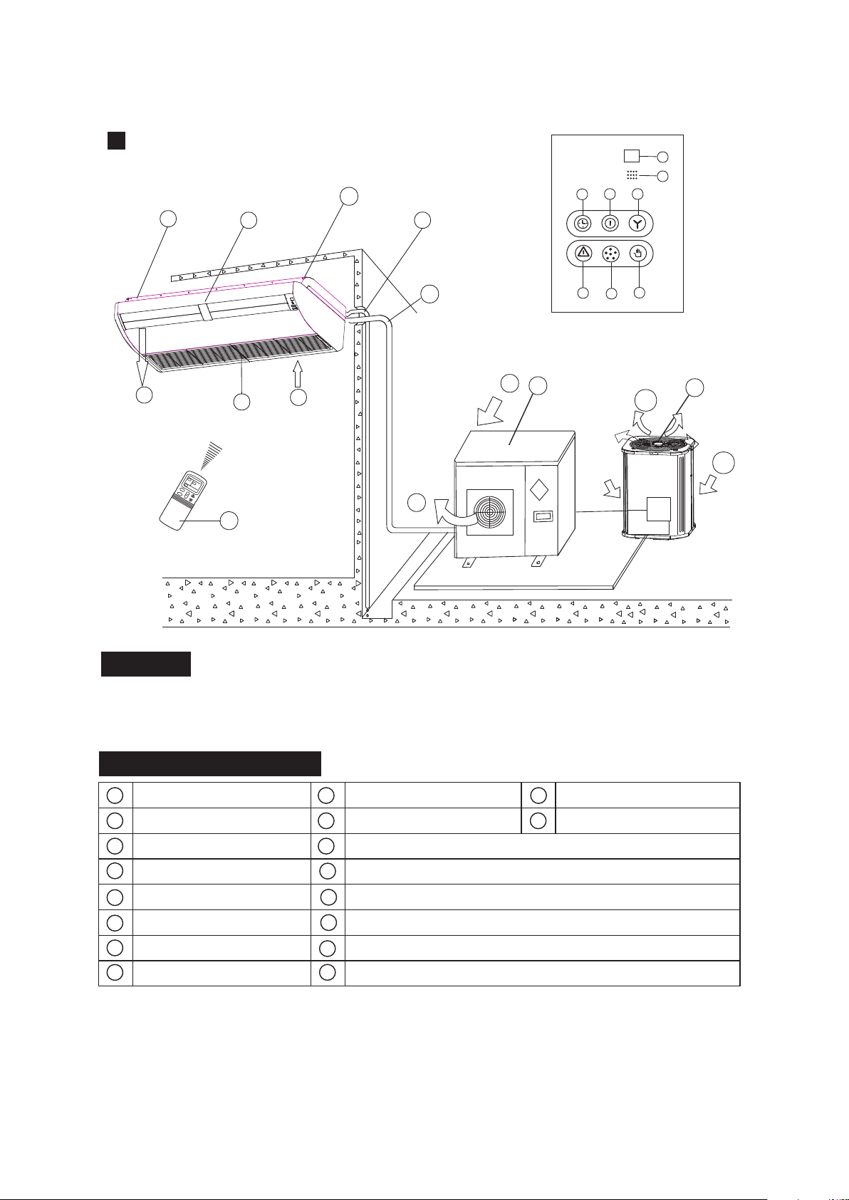
Display Panel
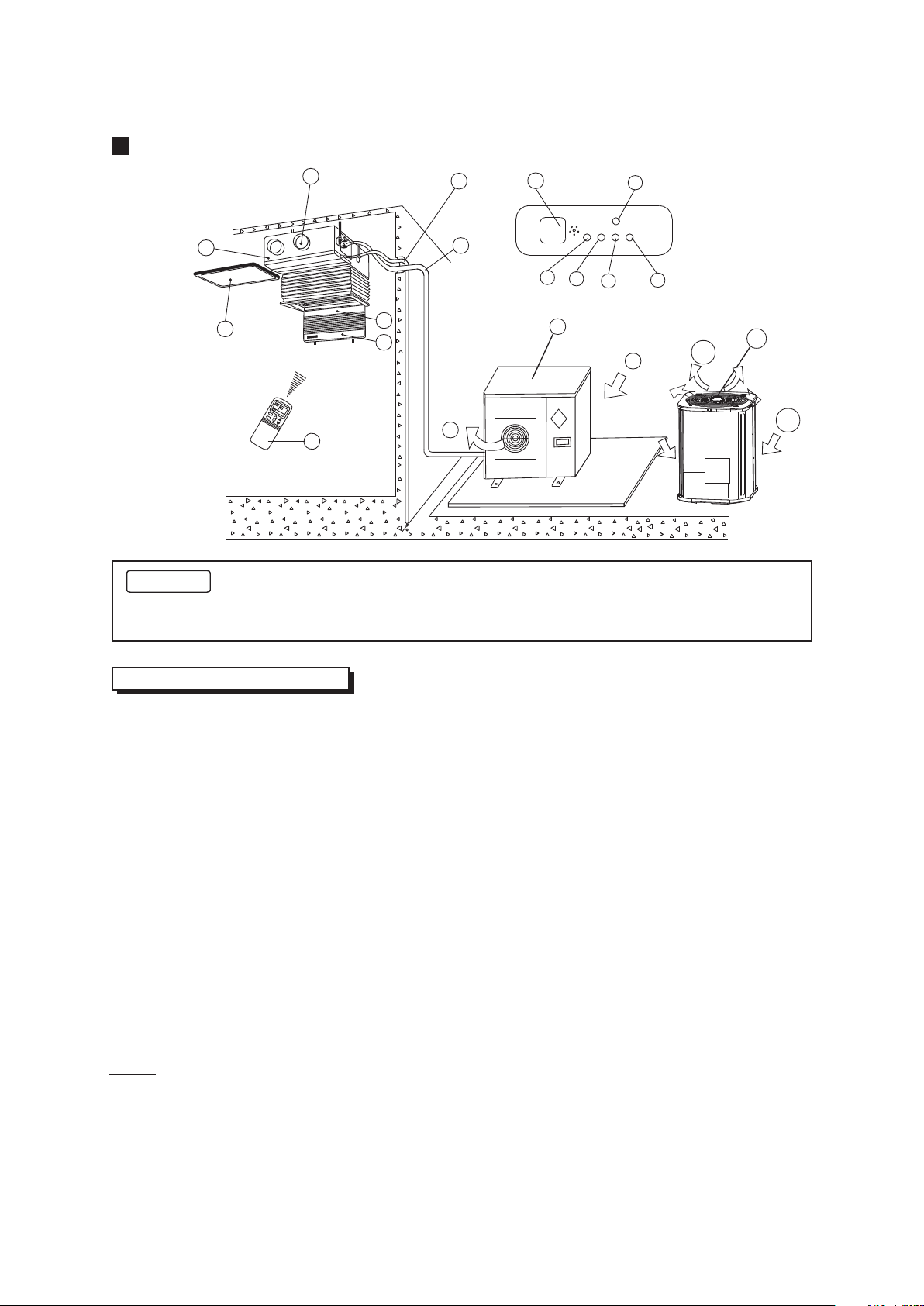
High-static Pressure Parvis Split Type
NOTICE!
This chart is based on 24000Btu/h type. So, a little differences may exist on the outlook and functions
from yours.
indoor unit
air-inlet
heat exchanger
outdoor unit
air-out
connecting pipe
E-Box
remote controller
air outlet
drain hose
infrared signal receiver
operation lamp
timer indicator
temporary button
PRE-DEF indicator
(cooling and heating type) or fan only indicator (cooling
alarm indicator
only type)
3
b
d
e
or
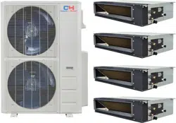
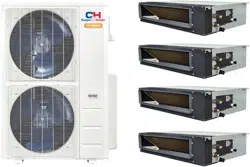
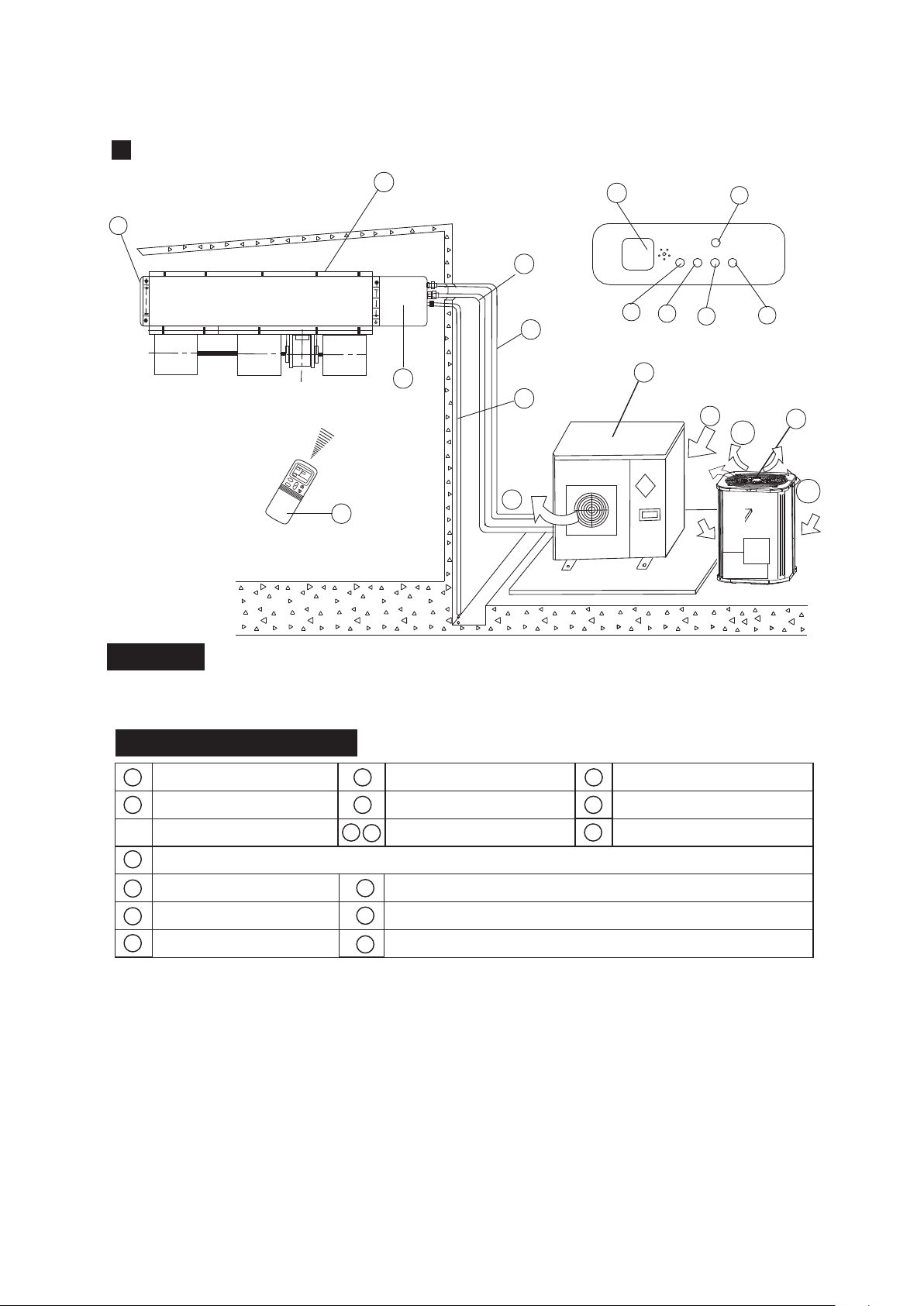
Duct and Ceiling Type
h
b
f
d
d
e
i
m
n
l
p
o
c
j
a
g
k
NOTICE!
This chart is based on 24000Btu/h type. So, a few differences may exist on the outlook and
functions from yours.
a) indoor unit b) outdoor unit
c) remote controller d) air-in
e) air-out f ) air outlet
g) air flow louver (at air outlet) h) connecting pipe
i ) drain hose j ) air inlet (with air filter in it)
k) infrared signal receiver l ) manual button
m) operation lamp n) timer indicator
o) PRE-DEF indicator p) alarm indicator
(NOTICE: In the case of "cooling only type", it is the "FAN ONLY" indicator.)
NAMES AND FUNCTIONS
4
b
d
e
or
NOTE:
All the pictures in this manual are for explanation purpose
only. There may be slightly different from the air conditioner
you purchased (depend on model ). The actual shape shall
prevail.
NOTICE!
This chart is based on 24000Btu/h. type. So, a few differences may exist on the outlook and functions from yours.
For Slim Duct Type
f
b
d
e
i
m
n
l
p
o
c
温度
时钟
风速
模
式
风速
开
关
温度
自动
a
Display Panel
h
g
k
j
NAMES AND FUNCTIONS
b
c
f
a
d
e
g
h
i
j
k
m
o
p
l
n
indoor unit
air-out
outdoor unit
air-inlet
connecting pipe
E-Box
remote controller
air- outlet
drain hose
infrared signal receiver
operation lamp
timer indicator
temporary button
PRE./DEF. indicator
(cooling and heating type) or fan only indicator (cooling
alarm indicator
only type)
5
b
d
e
or
NAMES AND FUNCTIONS
h
b
d
e
i
m
n
l
p
o
b
c
f
a
d
e
g
h
i
j
k
m
o
p
l
n
c
温度
时钟
风速
模
式
风速
开
关
温度
自动
k
f
d
j
a
f
g
Display Panel
indoor unit
air-out
heat exchanger
outdoor unit
air-outlet
connecting pipe
E-Box
remote Controller
air- inlet
drain hose
infrared signal receiver
operation lamp
timer indicator
temporary button
PRE./DEF. Indicator
(Cooling and heating type) or fan only indicator (cooling
alarm indicator
only type)
For Slim DUCT with air inlet box Type
6
b
d
e
or
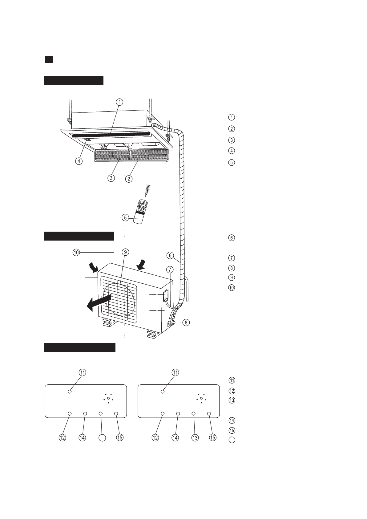
This picture is based on the type of 18000Btu/h, So the appearance and function may be
slightly different from the unit you purchased.
12 13
14
15
2
6
7
4
3
8
5
1
9
11
10
Indoor Unit Assy
Outdoor Unit Assy
Control board
Inlet
Outlet
Manual
OPERATION
TIMER
DEF./FAN.
ALARM
12
12
13
13
14
14
15
15
11
11
10
10
10
SET
OPERATION
TIMER
DEF./FAN.
ALARM
Indoor Unit
Air outlet
Drain hose
Drain Pump (Internal installed),water drain from indoor unit.
Infrared Signal receiver
Timer indicator
Alarm indicator
Defrost indicator heating/cooling type or fan indicator (cooling
only type)
Outdoor Unit
Vertical louver
Manual button/SET button
Remote Controller
Connecting pipe
Run lamp
1
7
10
4
9
13
15
2
3
Parts Names:
11 12
14
8
5
6
Air Inlet (Air filter installed inside to prevent the dust)
Four-way Cassette(slim) Type
7
NOTE:
These three indication lamps flash in cycles when solar
PV ECO function is activated.(Applicable to the unit adopts
solar photovoltaic system only.)
OUTDOOR UNIT
Display panel
INDOOR UNIT
Outlet louver
Inlet
Filter
Display panel
Remote controller
Refrigerant connecting, drain
hose pipe
Electric wiring
Trap
Air outlet
Air inlet(side and rear)
MANUAL
RUN
FAN
TIMER
ALARM
inlet
TEMP
CLOCK
SPEED
C
MODE
FAN
I
O
TEMP
inlet
outlet
MANUAL
RUN
TIMER
DEF
ALARM
MANUAL
RUN
TIMER
FAN
ALARM
MANUAL button
Run lamp
FAN indicator(Cooling/Heating
type without)
TIMER indicator
ALARM indicator
DEF. indicator(Cooling-only type
without)
16
INDOOR UNIT
DISPLAY PANEL
OUTDOOR UNIT
16
One-way Cassette Type
8
Cooling-only typeCooling&Heating type
f
c
g
Display Panel
NAMES AND FUNCTIONS
b
c
f
a
d
e
g
h
i
k
m
o
l
n
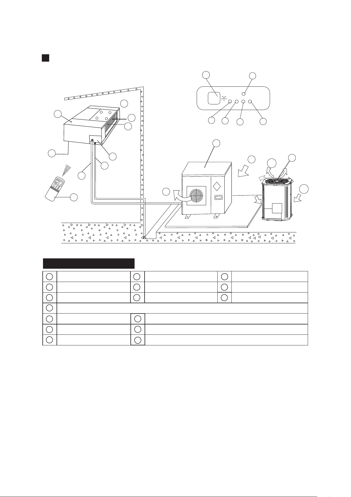
NOTICE!
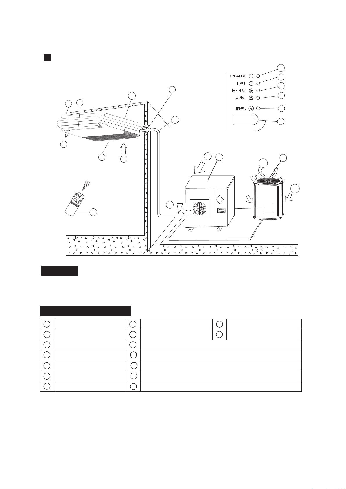
indoor unit
air-in
drain hose
outdoor unit
air flow louver (at air outlet)
air inlet (with air filter in it)
installation part
remote controller
connecting pipe
infrared signal receiver
operation lamp
timer indicator
temporary button
alarm
indicator
j
FAN/DEF indicator
, ,
(For cooling and heating type, it s DEF.,for cooling only type, it s FAN)
P
air-out
Ceiling & Floor Type(for )VERTICAL DISCHARGE AIR CONDITIONER
9
The chart based on one model of our product is for reference only, which may be different from
the unit you purchased.
n
m
o
l
k
J
i
a
e
d
h
p
b
d
p
b
d
p
or
f
c
g
Display Panel
NAMES AND FUNCTIONS
b
c
f
a
d
e
g
h
i
k
m
o
l
n
NOTICE!
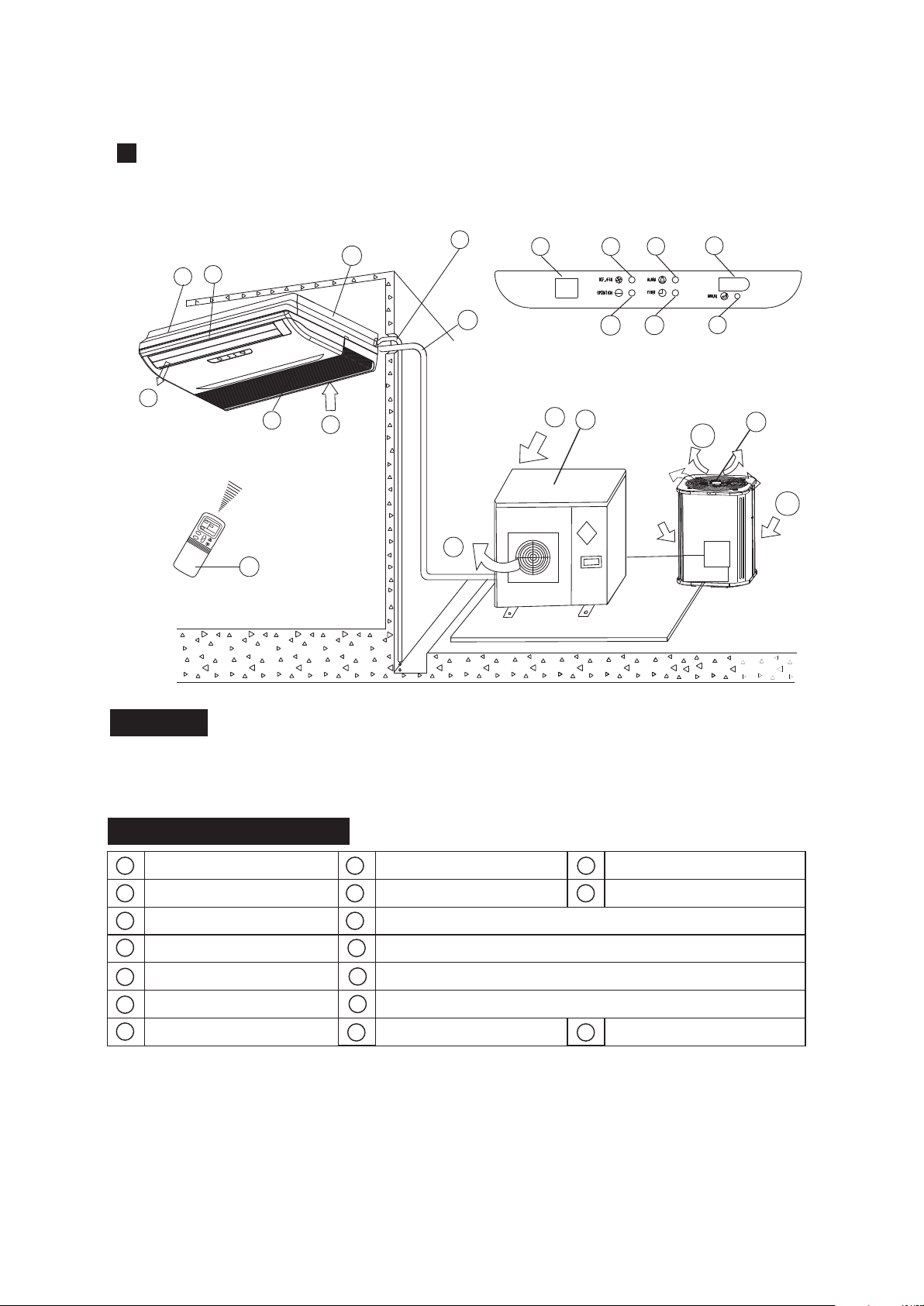
indoor unit
air-in
drain hose
outdoor unit
air flow louver (at air outlet)
air inlet (with air filter in it)
installation part
remote controller
connecting pipe
infrared signal receiver
operation lamp
timer indicator
temporary button
Alarm
Indicator
j
FAN/DEF indicator
, ,
(For cooling and heating type, it s DEF.,for cooling only type, it s FAN)
P
air-out
Ceiling & Floor Type
10
The chart based on one model of our product is for reference only, which may be different from
the unit you purchased.
i
a
e
d
h
p
b
d
p
n
m
o
l
k
Jq
q
Temperature display
b
d
p
or

f
c
g
Display Panel
NAMES AND FUNCTIONS
b
c
f
a
d
e
g
h
i
k
m
o
l
n
NOTICE!
indoor unit
air-in
drain hose
outdoor unit
air flow louver (at air outlet)
air inlet (with air filter in it)
installation part
remote controller
connecting pipe
infrared signal receiver
operation lamp
timer indicator
temporary button
Alarm
Indicator
j
FAN/DEF indicator
, ,
(For cooling and heating type, it s DEF.,for cooling only type, it s FAN)
P
air-out
Ceiling & Floor Type
11
The chart based on one model of our product is for reference only, which may be different from
the unit you purchased.
i
a
e
d
h
p
b
d
p
q
Temperature display
b
d
p
or
o
k
l
m j
n
q
MANUAL
OPERATION
TIMER
DEF./FAN
ALARM
f
i
n
m
o
c
l
a
j
k
g
e
d
Display Panel
h
p
NAMES AND FUNCTIONS
b
c
f
a
d
e
g
h
i
k
m
o
l
n
NOTICE!
indoor unit
air-in
drain hose
outdoor unit
air flow louver (at air outlet)
air inlet (with air filter in it)
installation part
remote controller
connecting pipe
infrared signal receiver
operation lamp
timer indicator
temporary button
alarm
indicator
j
FAN/DEF indicator
, ,
(For cooling and heating type, it s DEF.,for cooling only type, it s FAN)
P
air-out
Ceiling & Floor Type
12
The chart based on one model of our product is for reference only, which may be different from
the unit you purchased.
b
d
p
b
d
p
or
f
i
c
a
g
e
d
Display Panel
h
p
NAMES AND FUNCTIONS
b
c
f
a
d
e
g
h
i
k
m
o
l
n
NOTICE!
indoor unit
air-in
drain hose
outdoor unit
air flow louver (at air outlet)
air inlet (with air filter in it)
installation part
remote controller
connecting pipe
operation lamp
timer indicator
manual
button
warning
indicator
j
FAN/DEF indicator
, ,
(For cooling and heating type, it s DEF.,for cooling only type, it s FAN)
P
air-out
Ceiling & Floor Type
The chart based on one model of our product is for reference only, which may be different from
the unit you purchased.
b
d
p
b
d
p
or
M
JK
I
n
O
13
beep indicator
Q
infrared signal receiver
Q
R
R
temporary indicator
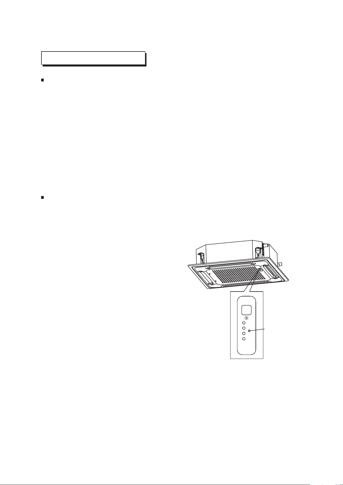
MANUAL OPERATION
Ceiling & Floor
This function is used to operate the unit temporarily in case you misplace the remote controller or its
batteries are exhausted. Two modes including AUTO and FORCED COOL can be selected through
the TEMPORARY BUTTON on the air-in grill control box of the indoor unit. Once you push this
button, the air conditioner will run in such order: AUTO, FORCED COOL, OFF, and back to AUTO.
AUTO
The OPERATION lamp is lit, and the air conditioner will run under AUTO mode. The remote
controller operation is enabled to operate according to the received signal.
FORCED COOL
The OPERATION lamp flashes, the air conditioner will turn to AUTO after it is enforced to cool
with a wind speed of HIGH for 30 minutes. The remote controller operation is disabled.
OFF
The OPERATION lamp goes off. The air conditioner is OFF while the remote controller operation
is enabled.
1
2
3
TEMPORARY
BUTTON
Four-way Cassette
This function is used to operate the unit temporarily in case you misplace the remote controller or its
batteries are exhausted. Two modes including AUTO and mandatory COOL can be selected through
the TEMPORARY BUTTON on the air inlet grill control box of the indoor unit. Once you push this
button, the air conditioner will run in such order: AUTO, mandatory COOL, OFF, and back to AUTO.
AUTO
The OPERATION lamp is lit, and the air
conditioner will run under AUTO mode. The
remote controller operation is enabled to operate
according to the received signal.
OFF
The OPERATION lamp goes off. The air
conditioner is OFF while the remote controller
operation is enabled.
MANDATORY COOL
The OPERATION lamp flashes, the air conditioner
will turn to AUTO after it is enforced to cool with a
wind speed of HIGH for 30 minutes. The remote
controller operation is disabled.
1
2
3
14
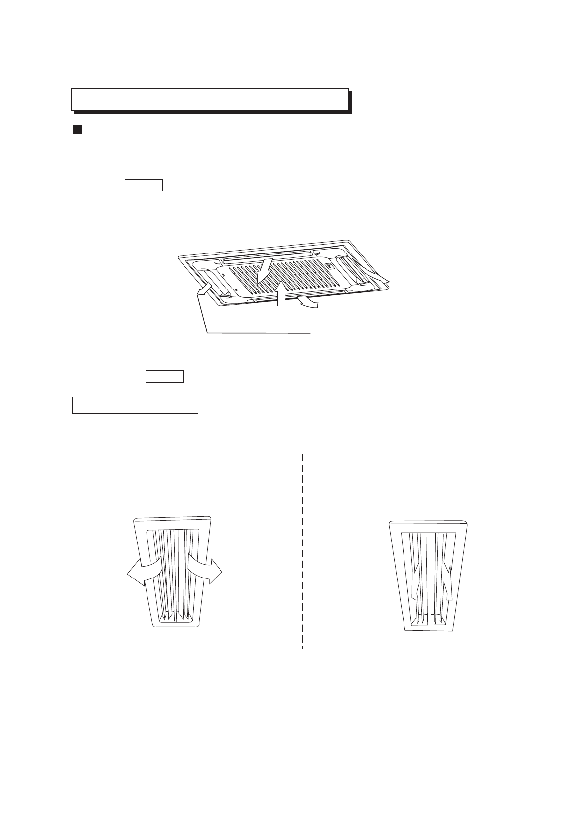
ADJUSTING AIR FLOW DIRECTION
Cassette Type
While the unit is in operation, you can adjust the air flow louver to change the flow direction and natu-
ralize the room temperature evenly. Thus you can enjoy it more comfortably.
1. Set the desired air flow direction.
Push the SWING button to adjust the louver to the desired position and push this button again to
maintain the louver at this position.
2. Adjust the air flow direction automatically.
Push the SWING button, the louver will swing automatically.
While this function is set, the swing fan of indoor unit runs; otherwise, the swing fan doesn't run. The
0
swing scale of every side is 30 . When the air conditioner isn't in operation (including when "TIMER
ON" is set), the SWING button will be disabled.
The following is how to adjust air flow direction when air outlet part (separately saled) is
used with the indoor unit.
Heating
To effectively heat the bottom of the room,
Please set the louver so that the air can
come out downwards.
Duct and Ceiling Type
Cooling
To effectively cool the whole room, please
set the louver so that the air can come out
horizontally.
ADJUST IT UP AND DOWN
15
MAINTENANCE
16
WARNING
Cleaning the indoor unit and remote controller
WARNING
Before you clean the air conditioner, be sure to disconnect the power supply plug.
If you do not plan to use the unit for at least 1 month.
(1) Operate the fan for about half a day to dry the inside of the unit.
(2) Stop the air conditioner and disconnect power.
(3) Remove the batteries from the remote controller.
!
Use a dry cloth to wipe the indoor unit and remote controller.
A cloth dampened with cold water may be used on the indoor unit if it is very dirty.
Never use a damp cloth on the remote controller.
Do not use a chemically-treted duster for wiping or leave such material on the unit for long,
because it may damage or fade the surface of the unit.
Do not use benzine, thinner, polishing powder, or similar solvents for cleaning. These may
cause the plastic surface to crack or deform.
CAUTIONS
!
Checks before operation
Cleaning the air filter
Check that the wiring is not broken off or disconnected.
Check that the air filter is installed. (Some air-conditioners haven't air filters.)
Check that the outdoor unit air outlet or inlet is not blocked.
Before you clean the air conditioner, be sure to disconnect the power supply plug.
The air filter can prevent the dust or other particulate from going inside .In case of blockage of the filter , the
working efficiency of the air conditioner may greatly decrease .Therefore , the filter must be cleaned once two
weeks during long time usage.
If the air conditioner is positioned in a dust place , the cleaning frequency of the air filter must be increased .
If the accumulated dust is too heavy to be cleaned , please replace the filter with a new one(replaceable air
filter is an optional fitting).
The filter cleaning should be performed by a suitable service provider.
CAUTIONS
!
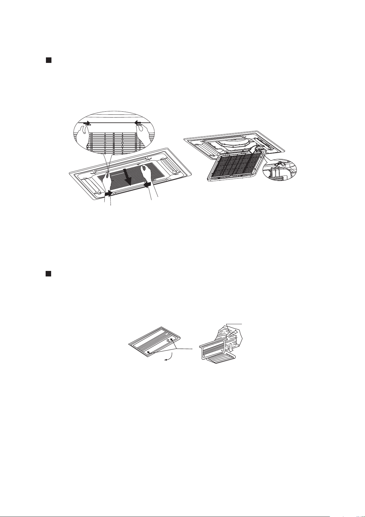
2. Take out the air-in grill (together with the air filter shown in Sketch B)
o
Pull the air-in grill down at 45 and lift it up to take out the grill.
3. Dismantle the air filter
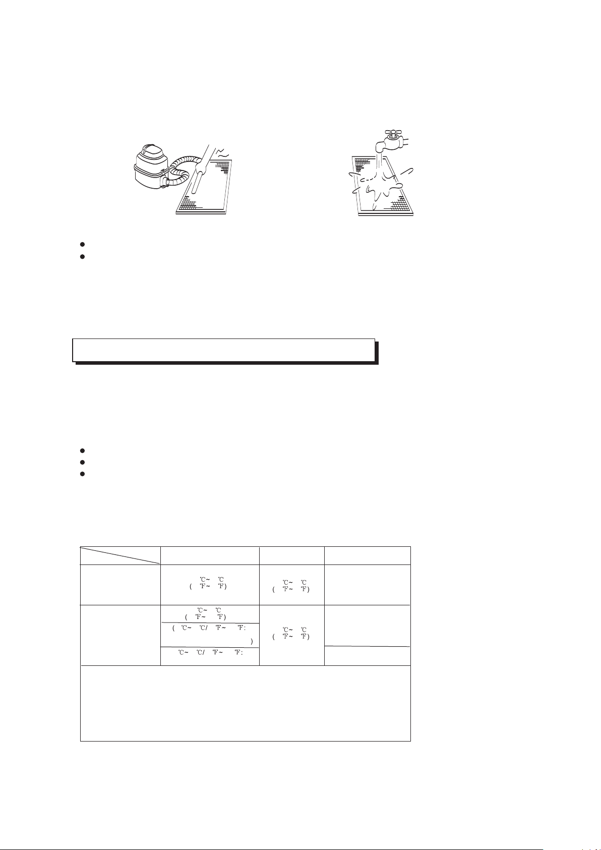
4. Clean the air filter(Vacuum cleaner or pure water may be used to clean the air filter. If the dust
accumulation is too heavy , please use soft brush and mild detergent to clean it and dry out in cool
place) .
A B
1. Open the air-in grill
Push the grill switches towards the middle simultaneously as indicated in sketch A. Then pull down
the air-in grill.
Cautions: The control box cables ,which are originally connected with the main body electrical terminators
must be pulled off before doing as indicated above.
Cassette Type
17
Duct and Ceiling Type
Clip
Open<
1. Open the air-in grill
Push the grill switches towards the middle simultaneously as indicated in follow figure sketch.
Then pull down the air-in grill.
Cautions: The control box cables ,which are originally connected with the main body electrical
terminators must be pulled off before doing as indicated above.
2. Take out the air-in grill.
3. Dismantle the air filter
Three-minute protection feature
Power failure
A protection feature prevents the air conditioner from being activated for approximately 3 minutes
when it restarts immediately after operation.
Power failure during operation will stop the unit completely.
Disconnect the unit with the power and then connect the unit with the power again. Push the ON/OFF
button on the remote controller to restart operation.
The OPERATION lamp on the indoor unit will start flashing when power is restored.
To restart operation, push the ON/OFF button on the remote controller.
Lightning or a car wireless telephone operating nearby may cause the unit to malfunction.
4. Clean the air filter (Vacuum cleaner or pure water may be used to clean the air filter. If the dust
accumulation is too heavy , please use soft brush and mild detergent to clean it and dry out in cool
place) .
Fig. 1 Fig. 2
The air-in side should face up when using vacuum cleaner. (See Fig. 1)
The air-in side should face down when using water. (See Fig. 2)
Cautions : Do not dry out the air filter under direct sunshine or with fire.
5. Re-install the air filter
6. Install and close the air-in grill in the reverse order of step 1 and 2 and connect the control box
cables to the corresponding terminators of the main body .
Note: High-static Pressure Parvis Split Type has no air filter.
18
AIR CONDITIONER OPERATIONS AND PERFORMANCE
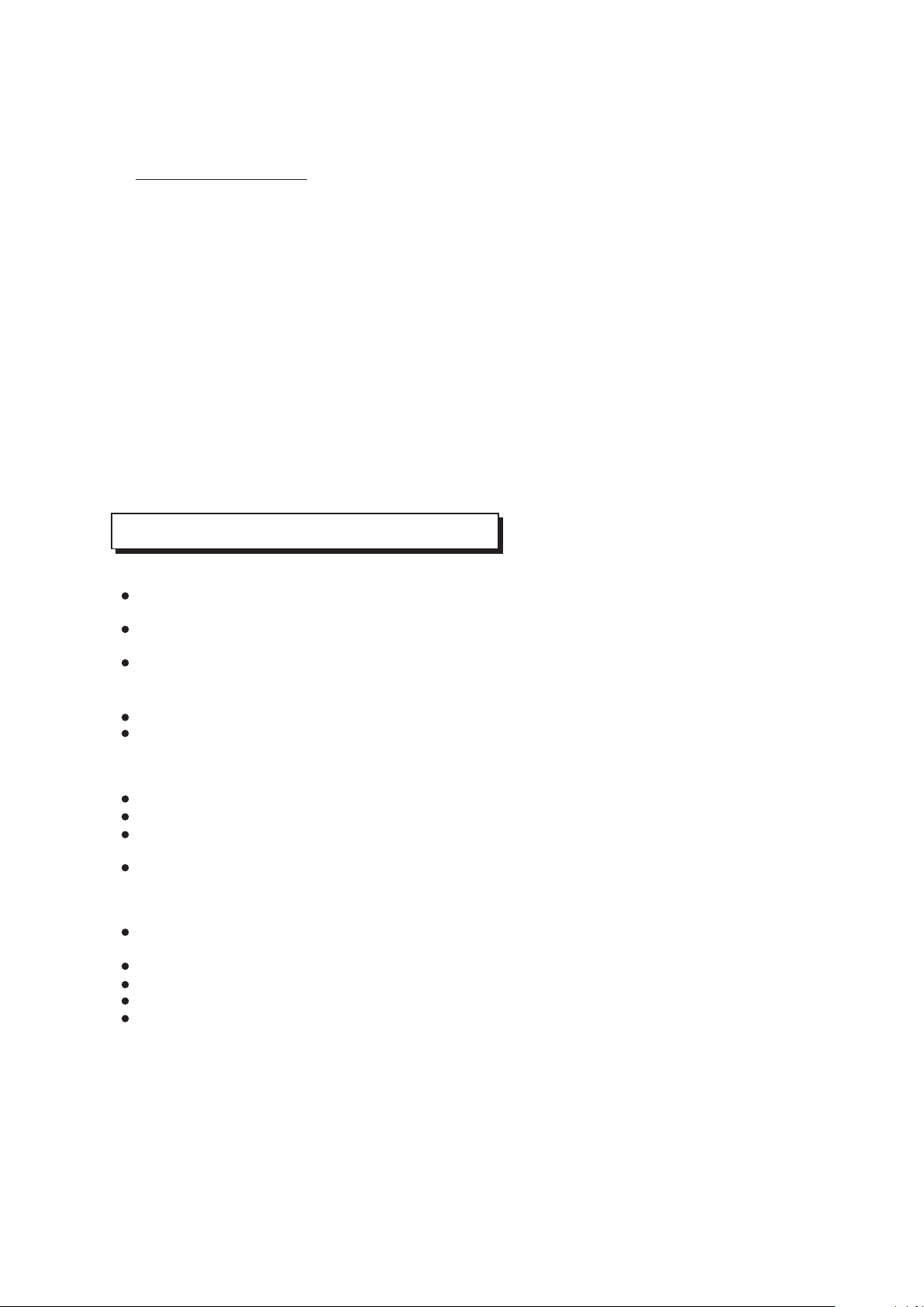
Air conditioner operating conditions
For proper performance, run the air conditioner under the following temperature conditions:
Mode
Cooling operation
Heating operation
Drying operation
Temperature
1. If air conditioner is used outside of the above conditions, certain safety protection features
may come into operation and cause the unit to function abnormally.
2. Room relative humidity less than 80%. If the air conditioner operates in excess of this
figure, the surface of the air conditioner may attract condensation. Please sets the vertical
air flow louver to its maximum angle (vertically to the floor), and set HIGH fan mode.
3. Optimum performance will be achieved within these operating temperature.
Room temperature
Outdoor temperature
NOT E:
17 32
62 90
0 30
32 86
-7 24
20 76
18 43
64 109
-7 43 20 109
For the models with low
temperature cooling system
18 52 64 126
For special tropical models
(For special tropical models)
O O O O
17 C~ 32 C/ 62 F~ 90 F
O O O O
18 C~ 43 C/64 F~109 F
O O O O
18 C~52 C/64 F~126 F
Relocation
If you move out or if it is desired to relocate the air conditioner, consult your dealer, because special
skills to withdraw Freon, purge air and perform other operations are required.
Location:
Be careful of noise or vibrations
Wire
During cooling operation, the air conditioner will dry the room air, so please fix a pipe to drain all the
water away from the air conditioner.
Please let the indoor unit more than one metre away from the TV set and the radio in order to avoid
the picture and noise interference.
Powerful radio transmitters or any other devices radiating high frequency radio waves can cause
the air conditioner to malfunction. Please consult the dealer where you purchased the air conditio-
ner before installing it.
Don't fix the unit in the dangerous region with combustible gas or volatile matter.
If the air conditioner operates in an atmosphere containing oils (machine oil), salt (near a coastal
area), sulfide gas (near a hot spring), etc., such substances may lead to failure of the air conditioner.
Please fix the unit in the stable place to avoid the noise or vibrations.
The noise near the air outlet of the outdoor unit may enter the air exit.
Locate the outdoor unit where noise emitted by it or hot air from its air outlet will cause no nuisance
to your neighbours.
If the air conditioner sounds abnormal during operation, contact the dealer where you purchased the
air conditioner.
To avoid the electric shock, please link the air conditioner with the ground. The plug in the air
conditioner has joined the ground wiring, please don't change it freely.
The power socket is used as the air conditioner specially.
Don't pull the power wiring hard.
When linking the air conditioner with the ground, observe the local rulers.
If necessary, use the power fuse or the circuit, breaker or the corresponding scale ampere.
If you want to change the power wiring, please contact the centre service of the local MD electric
appliance.
INSTALLATION
19
Special functions
Louver Angle Memory Function(optional):
For some models, the machine is special designed with louver angle memory function.
Power failure during operation or pressing the ON/OFF button on the remote controller
will stop the unit completely.When the power restores or pressing the ON/OFF button
on the remote controller again,the unit restarts automatically with the previous open
angle of the horizontal louver by the memory function.So we strongly recommend that the
open angle of the horizontal louver should not be set too small,in case the condensed
water forms and drops from the horizontal louver. Press the Manual control button and
the open angle of the horizontal louver will be restored to the standard angle.
Refrigerant Leakage Detection(optional):
With this new technology, the dipsplay area will appear EC (if applicable) and the LED
indication lamps continue flashing when the outdoor unit detects refrigerant leakage.
Before you ask for servicing or repairs, check the following points.
Setting Change is Impossible
Symptoms
Causes
Reason and Disposal
The fan speed can not be
changed.
Check whether the MODE
indicated on the display is
"AUTO"
Check whether the MODE
indicated on the display is
"DRY"
When the automatic mode is
selected, the air conditioner
automatically selects the fan
speed.
When dry operation is selected,
the air conditioner automatically
select the fan speed. The fan
speed can be selected during
"COOL" and "FAN ONLY", and
"HEAT"
TROUBLES AND CAUSES
(CONCERNING REMOTE CONTROLLER)
TROUBLES AND CAUSES
Before you ask for servicing or repairs, check the following points.
The power fuse is blown or the circuit breaker has been tripped.
The batteries in the remote controller are exhausted.
The timer is set.
A bad odor comes from the air conditioner.
The air inlet or outlet of the outdoor unit is blocked.
Doors or windows are open.
The air filter is clogged with dust.
The louver is not at the correct position.
The fan speed is set to low.
The temperature setting is too high or too low.
Smells impregnated in the wall, carpet, furniture, clothing, or furs, are coming out. A white mist
of chilled air or water is generated from the outdoor unit.
The indicator lamps flash rapidly (five times per second), you disconnect the unit with the power
and then connect the unit with the power again after two or three minutes but the lamps still flash.
Switch operations are erratic.
The fuse is blown frequently or the circuit breaker is tripped frequently.
Foreign matter or water has fallen inside the air conditioner.
Any other unusual condition is observed.
Recheck
These are not failures
Inoperative
Room air is smelly.
Does not cool or heat well.
If any of the following conditions occur, stop the air conditioner immediately, set to off the power
switch, and contact the dealer:
CAUTION
!
20
The Transmission Indicator " " Never Comes On
The Display Never Comes On
Symptoms
Symptoms
Causes
Causes
Reason and Disposal
Reason
The remote control signal is
not transmitted even when
the ON/OFF button is pushed.
The TEMP. indicator does
not come on.
Check whether the batteries
in the remote controller are
exhausted.
Check whether the MODE
indicated on the display is
"FAN ONLY".
FAN ONLY
The remote control signal is
not transmitted, because the
power supply is off.
The temperature cannot be
set during fan only operation.
The Display Goes Off
Symptoms
Causes
Reason
The indication on the display
disappears after a lapse of
time.
The ON TIMER indicators
go off after a lapse of certain
time.
Check whether the timer
operation has come to an
end when the OFF TIMER
is indicated on the display.
Check whether the timer
operation is started when
the ON TIMER is indicated
on the display.
The air conditioner operation
stops since the set time
elapsed.
When the time set to start the
air conditioner is reached, the
air conditioner will automatically
start and the appropriate
indicator will go off.
The Signal Receiving Tone does Not Sound
Symptoms
Causes
Disposal
No receiving tone sounds
from the indoor unit even
when the ON/OFF button is
pushed.
Check whether the signal
transmitter of the remote
controller is properly directed
to the receiver of the indoor
unit when the ON/OFF button
is pushed.
Direct the signal transmitter of
the remote controller to the
receiver of the indoor unit, and
then repeatly push the ON/
OFF button twice.
Buttons on the remote
controller don't work.
Press Reset button.
21
Malfunction
1
2
3
4
5
6
7
8
9
10
12
13
14
15
16
17
18
19
20
21
22
23
24
25
11
Indoor EEPROM error
Water-level alarm malfunction
Indoor room temperature sensor
open circuit or short circuit
Indoor fan speed malfunction
Communication malfunction
between two indoor units (for
twins model)
Refrigerant leakage detection
malfunction
Evaporator coil temperature
sensor open circuit or short circuit
Other malfunction of twins model
Outdoor room temperature sensor
open circuit or short circuit
Current overload protection
High/Low voltage protection
Inverter module IPM protection
Lifting panel is not closed
Lifting panel malfunction
Lifting panel communication
checking channel is abnormal
T2b sensor error
Outdoor EEPROM error
Outdoor fan speed malfunction
(Only for DC fan motor)
Discharging air temperature
sensor error
Outdoor condenser pipe
temperature sensor error
E0.
E1.
E3.
E4.
E5.
EC.
EE.
E8.
E9.
F0.
F1.
F2.
F3.
F4.
F5.
F6.
F7.
F8.
F9.
P0.
P1.
P2.
P3.
P4.
P5.
ON.
ON.
ON.
ON.
ON.
ON.
ON.
ON.
ON.
ON.
Flash.
Flash.
Flash.
Flash.
Flash.
Flash.
High temperature protection of
compressor top
Mode conflict
Compressor drive error
Outdoor low temp. Protection
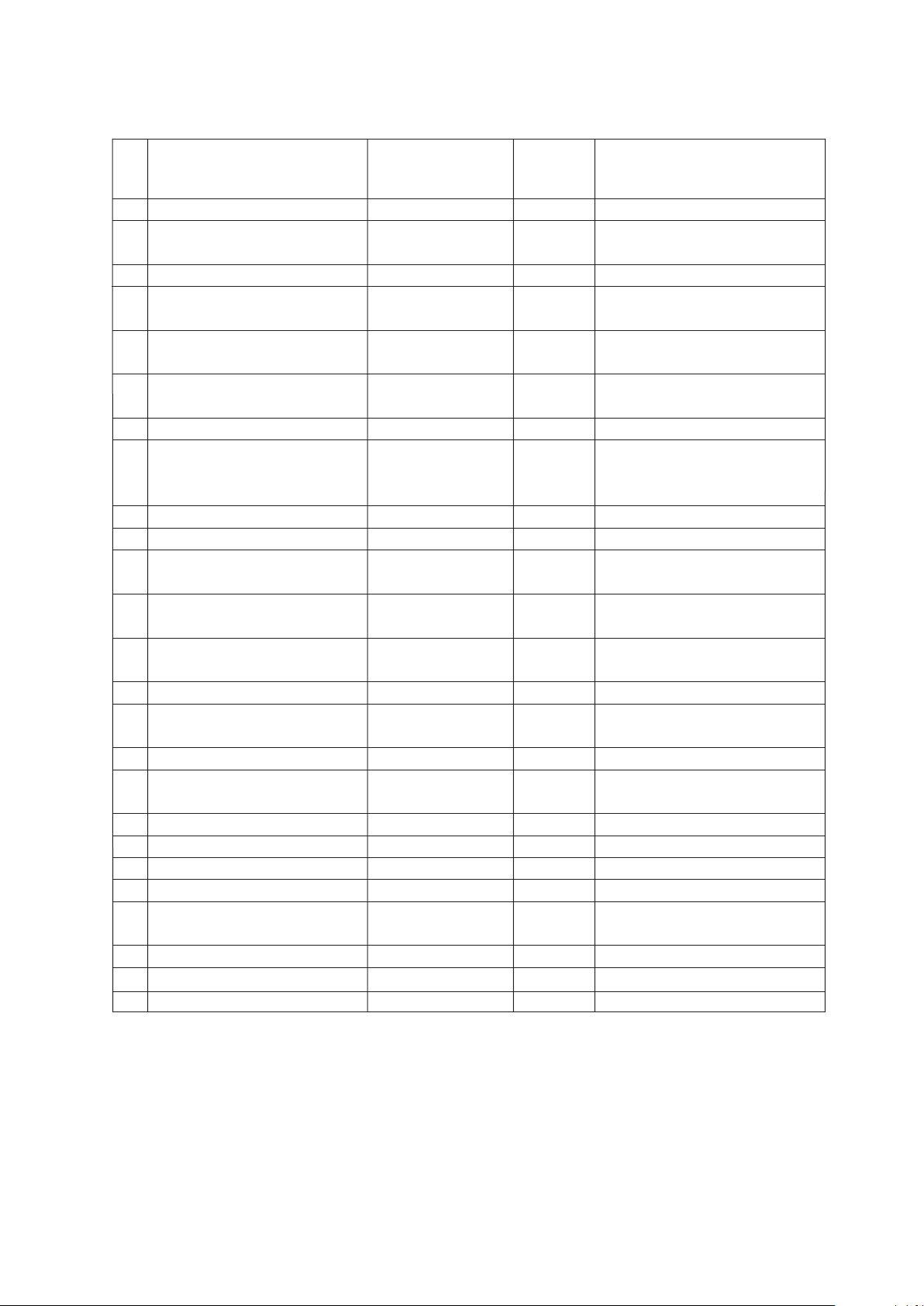
The following displays indicate an error or problem:
The displayed error code differs from appliance to appliance. The actual display of the indoor
unit shall prevail.
NO
Display (nixie tube)
timer lamp
running lamp (flashes per second)
Communication malfunction
between indoor and outdoor units
OFF
OFF
OFF
OFF
OFF
OFF
OFF
OFF
OFF
1
2
4
5
6
7
8
9
10
1
2
3
4
5
6
7
8
9
1
10
1
2
3
4
5
6
LIMITED WARRANTY STATEMENT
MULTI ZONE INVERTER AIR CONDITIONING SYSTEM WITH HEAT PUMP
FOR WARRANTY SERVICE OR REPAIR:
Contact your installing contractor. You may find the installer’s name on the equipment or in your Owner’s packet.
Complete product registration below and send back by e-mail at [email protected]
PRODUCT REGISTRATION:
Model No.: ______________________________________________________________________________________________
Serial No.: _______________________________________________________ Date of Installation: ______________________
Owner Name: ____________________________________________________________________________________________
Address of Installation:_____________________________________________________________________________________
Installing Contractor: ______________________________________________________________________
____
____________
Address: ________________________________________________________________________________________
Phone No. / E-mail: _______________________________________________________________________________
C&H distributor (hereinafter “Company”) warrants this product against failure due to defect in materials or workmanship
under normal use and maintenance as follows. All warranty periods begin on the date of original installation. If the date cannot
be verified, the warranty period begins one hundred twenty (120) days from date of manufacture. Damage resulting from
failure to use, install or maintain the product in a manner consistent with our/manufacturer’s recommendations shall render the
warranty void. Cooper&Hunter, at its option, may request a report from a qualified technician prior to honoring a warranty
claim. If a part fails due to defect during the applicable warranty period Company will provide a new or remanufactured part, at
Company’s option, to replace the failed defective part at no charge for the part. This limited warranty is subject to all provisions,
conditions, limitations and exclusions listed below.
●
A warranty period of Seven (7) years on compressor to the original registered end-user.
● A warranty period of Five (5) years on all parts to the original registered end user.
● A warranty period of One (1) year on the remote control provided with the original unit.
● Limited warranty applies only to systems that are properly installed by a state certified or licensed HVAC contractor,
under applicable local and state law in accordance with all applicable building codes and permits
; C&H installation
and operation instructions and good trade practices.
● Warranty applies only to products remaining in their original installation location.
● Defective parts must be returned to the distributor through a registered servicing dealer for credit.
www.cooperandhunter.us
This warranty should be registered on our web-site www.cooperandhunter.us
The warranty is only valid when installed by a Licensed HVAC Technician
Place Of Purchase:
________________________________________________________________________________________
Date of Purchase:
_______________________________________________________________________________
LIMITATIONS OF WARRANTIES:
ALL IMPLIED WARRANTIES AND/OR CONDITIONS (INCLUDING IMPLIED WARRANTIES OR
CONDITIONS OF MERCHANTABILITY AND FITNESS FOR A PARTICULAR USE OR PURPOSE) ARE LIMITED TO THE DURATION OF
THIS LIMITED WARRANTY. SOME STATES OR PROVINCES DO NOT ALLOW LIMITATIONS ON HOW LONG AN IMPLIED WARRANTY
OR CONDITION LASTS, SO THE ABOVE MAY NOT APPLY TO YOU. THE EXPRESS WARRANTIES MADE IN THIS WARRANTY ARE
EXCLUSIVE AND MAY NOT BE ALTERED, ENLARGED, OR CHANGED BY ANY DISTRIBUTOR, DEALER, OR OTHER PERSON,
WHATSOEVER.
THIS WARRANTY DOES NOT COVER
:
1. Labor or other costs incurred for diagnosing, repairing, removing, installing, shipping, servicing, or handling
of defective parts, replacement parts, or new units.
2. Product cleaning required prior to warranty service and repair.
3. Normal maintenance as outlined in the installation and servicing instructions or user's manual,
including filter cleaning and/or replacement and lubrication.
4. Failure, damage, or repairs due to faulty installation, misapplication, abuse, improper servicing,
unauthorized alteration, or improper operation.
5. Failure to start due to voltage conditions, blown fuses, open circuit breakers, or damages due to the
inadequacy or interruption of electrical service.
6. Failure or damage due to floods, winds, fires, lightning, accidents, corrosive environments (rust,
etc.), or other conditions beyond the control of Company.
7. Failure or damage of coils or piping due to corrosion on installations within one (1) mile of a sea coast or
a corrosive body.
8. Parts not supplied or designated by Company, or damages resulting from their use.
9. Products installed outside the continental USA and Canada.
10. Electricity or fuel costs, or increases in electricity or fuel costs for any reason whatsoever, including
additional or unusual use of supplemental electric heat.
11. Any cost to replace, refill, or dispose of refrigerant, including the cost of refrigerant.
12. Shipping damage or damage as a result of transporting the unit.
13. Accessories such as condensate pumps, line sets, and so forth.
14. Any special, indirect, or consequential property or commercial damage of any nature whatsoever. Some
states or provinces do not allow the exclusion of incidental or consequential damages, so the above limitation may
not apply to you.
This warranty gives you specific legal rights, and you may also have other rights which vary from state to state or province to
province.