Loading ...
Loading ...
Loading ...
14. WIRING
The appliance shall be installed in accordance with
national wiring regulations.
The air conditioner should use separate power supply
with rated voltage.
The external power supply to the air conditioner should
be grounded, which is linked to the ground wiring of the
indoor and outdoor unit.
The wiring work should be done by qualified persons
according to wiring diagram.
A circuit breaker and a residual current device (RCD) with
above 10mA rating shall be installed in the power circuit
according to the national rule.
Be sure to locate the power wiring and the signal wring
well to avoid cross-disturbance.
Do not turn on the power until you have confirmed
proper wiring.
The power cord type is H07RN-F.
The power connection for the air conditioner has to be
done at the main power distribution. The distribution has
to be of a low impedance, normally the required
impedance reaches at a 32 A fusing point.
No other equipment has to be connected with this power
line.
For detailed installation acceptance please refer to your
power supplier, if restrictions do apply for products like
washing machines, air conditioners or electrical ovens.
For power details of the air conditioner refer to the rating
nameplate of the product.
For any question contact your local dealer.
1
2
4
3
5
Refer to EMC Directive 2004/108/EC
To prevent flicker impressions during the start of the
compressor,following installation conditions do apply.
NOTE
Table 13-2
Fig.12-3
Pump maintainance:
Screw off four screws from drain pump.
Plug off pump power supply and water level switch cable.
Take off pump.
1.
2.
3.
Pump
Table 13-1
13. CONTROL(ONLY FOR INVERTER UNITS)
Horsepower code setting
13.1
The capacity of the system and the network address of
the air-conditioner can be set by the switches on the
indoor Main Control Board.
Before setting, turn off the power. After setting, restart
the unit.
Setting is not allowed when the unit is power on.
The capacity of the indoor unit has been set in the
factory according to the below table.
Horsepowe r code
ENC1
PO WER_S
0
1
2
3
4
5
6
7
8
9
A
B
C
D
E
F
ENC1
Note: The capacity
has been set in the
factory , anyone
can’t adjust it
except the qualified
person.
Toggle switch
Code
Capacity(kw)
4
5.3
5.6
5 7.1
7 9.0
8 10.5
9
14.0
16.0
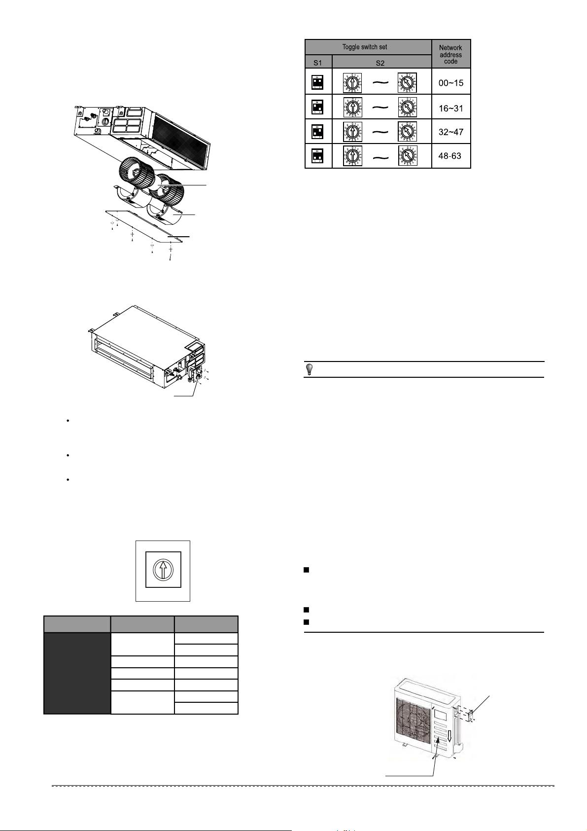
Every air-conditioner in network has only one network address
to distinguish each other. Address code of air-conditioner in
LAN is set by code switches S1 & S2 on the Main Control Board
of the indoor unit, and the set range is 0-63.
13.2 Network address set
Disassemble the cover.(If there isn't a cover on the outdoor
unit, disassemble the screw from the maintenance board, and
pull it in the direction of the arrow to remove the protection
board.) (Refer to Fig.14-1)
Connect the cables to the terminals correspondingly.
Re-install the cover or the protection board.
Connect the cable
14.1
The Specification of Power
14.2
(Refer to Table14-1~14-8)
Fig.13-1
Protection board
Wiring figure
14.3
(Refer to Fig.14-2~Fig.14-5)
1.split type outdoor unit
Cover
20
installation manual
Fig.12-2
12.1Motor and drain pump maintenance
Motor maintain:
Take off the ventilated panel.
Take off the blower housing.
Take off the motor.
1.
2.
3.
(Take rear ventilated as example)
Motor
Blower housing
Ventilated panel
For more details visit www.mrcool.com
Loading ...
Loading ...
Loading ...