Loading ...
Loading ...
Loading ...
5 ■English
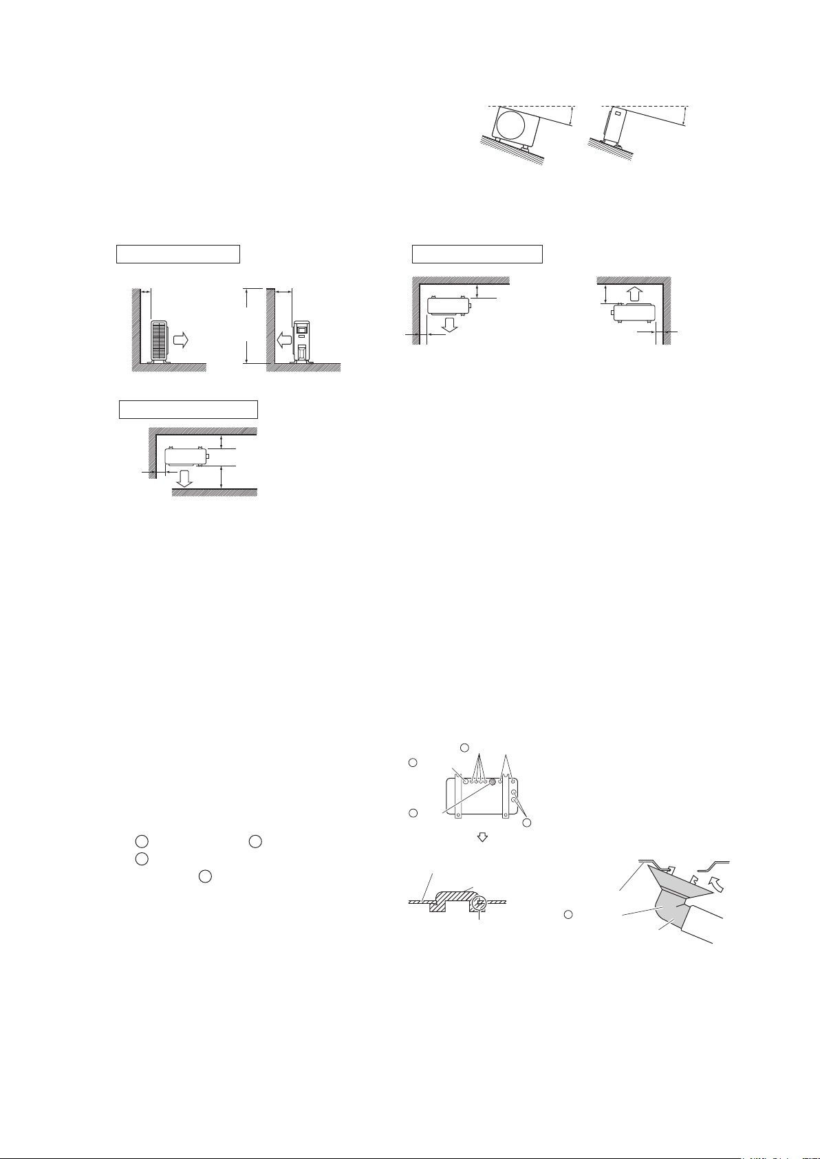
Installation Space Requirements
•
Position the unit on a horizontal surface.
Any tilt in the unit (front to back, right to left) should be 3° or less to the
horizontal.
•
Where a wall or other obstacle is in the path of the outdoor unit’s intake or
exhaustairow,followtheinstallationspacerequirementsbelow.
• For any of the below installation patterns, the wall height on the outlet
side should be 47-1/4 inch (1200mm) or less.
unit: inch (mm)
Top view
More than 3-15/16 (100)
More than
13-3/4 (350)
More than
1-15/16 (50)
Walls facing three sides
More than
3-15/16 (100)
More than
13-3/4 (350)
Side view
47-1/4
(1200)
or less
Wall facing one side
More than
1-15/16 (50)
More than
1-15/16 (50)
Top view
More than
3-15/16 (100)
Walls facing two sides
More than
13-3/4 (350)
Outdoor Unit Installation
1. Installing the outdoor unit
1)
When installing the outdoor unit, refer to “Precautions for Selecting a Location” and the “Outdoor Unit Installation Diagram”.
2) If drain work is necessary, follow the procedures in
“
2. Drain work
”
.
2. Drain work (only for heat pump models)
• Ifthedrainportiscoveredbyamountingbaseoroor
surface, place additional foot bases of at least 1-1/4
inch (30mm) in height under the outdoor unit’s feet.
• In cold areas, do not use a drain socket, drain caps
(1,2) and a drain hose with the outdoor unit. (Drain
water may freeze, impairing heating performance.)
1) Attach
C
drain cap (1) and
D
drain cap (2).
2) Attach
B
drain socket.
• When attaching
B
drain socket to the bottom
frame, make sure to connect the drain hose to the
drainsocketrst.
Viewed from
the side
Viewed from
the front
±3° or less
±3° or less
Bottom frame
Drain cap
Pinch the bottom
frame in.
Drain cap (1)
Drain cap (2)
D
Drain cap (2)
Air outlet side
B
Drain
socket
C
D
Bottom frame
Drain socket
Hose (available commercially,
inner dia. 5/8 ” (16mm))
B
01_EN_3P457793-1.indd 5 11/22/2016 10:46:28 AM
Loading ...
Loading ...
Loading ...