Loading ...
Loading ...
Loading ...
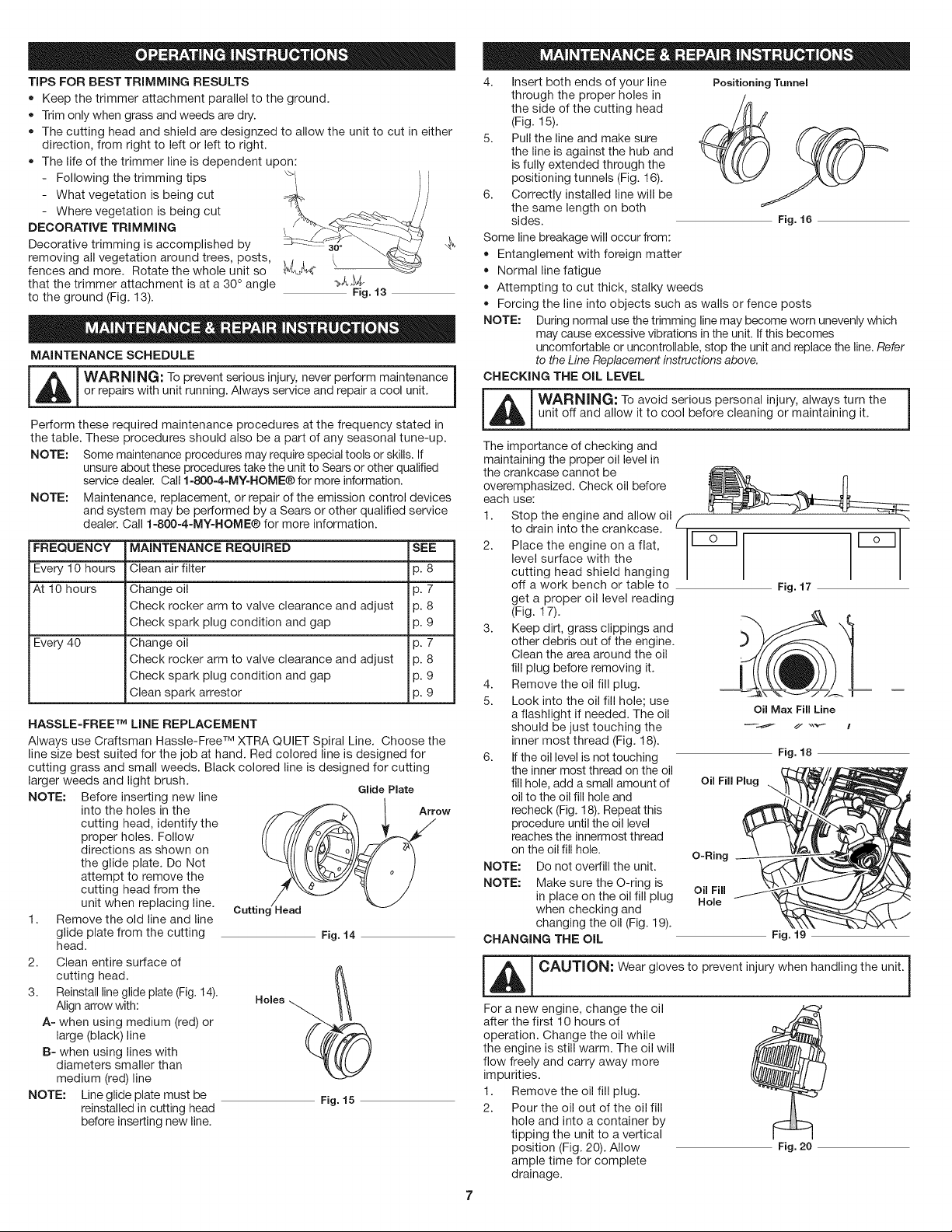
TiPS FOR BEST TRIMMING RESULTS
• Keep the trimmer attachment parallel to the ground.
• Trim only when grass and weeds are dry.
The cutting head and shield are designzed to allow the unit to cut in either
direction, from right to left or left to right.
The life of the trimmer line is dependent upon:
Following the trimming tips
- What vegetation is being cut
- Where vegetation is being cut
DECORATIVE TRIMMING
Decorative trimming is accomplished by _._
removing all vegetation around trees, posts,
fences and more. Rotate the whole unit so _#J_
that the trimmer attachment is at a 30 ° angle _J__
to the ground (Fig. 13). Fig. 13
MAINTENANCE SCHEDULE
-- i
_ ARNING: To prevent serious injury, never perform maintenance
or repairs with unit running. Always service and repair a cool unit.
Perform these required maintenance procedures at the frequency stated in
the table. These procedures should also be a part of any seasonal tune-up.
NOTE: Some maintenance procedures may require special tools or skills. If
unsure about these procedures take the unit to Sears or other qualified
service dealer. Call 1-800-4-MY=HOME® for more information.
NOTE: Maintenance, replacement, or repair of the emission control devices
and system may be performed by a Sears or other qualified service
dealer. Call 1-800-4-MY-HOME® for more information.
FREQUENCY MAINTENANCE REQUIRED SEE
Every 10 hours Clean air filter p. 8
At 10 hours Change oil p. 7
Check rocker arm to valve clearance and adjust p. 8
Check spark plug condition and gap p. 9
Every 40 Change oil p. 7
Check rocker arm to valve clearance and adjust p. 8
Check spark plug condition and gap p. 9
Clean spark arrestor p. 9
HASSLE-FREE TM LiNE REPLACEMENT
Always use Craftsman Hassle-Free TM XTRA QUIET Spiral Line. Choose the
line size best suited for the job at hand. Red colored line is designed for
cutting grass and small weeds. Black colored line is designed for cutting
larger weeds and light brush.
Glide Plate
NOTE: Before inserting new line
into the holes in the Arrow
cutting head, identify the
proper holes. Follow
directions as shown on
the glide plate. Do Not
attempt to remove the
cutting head from the
unit when replacing line.
Cuttinc Head
1. Remove the old line and line
glide plate from the cutting Fig. 14
head.
2. Clean entire surface of
cutting head.
3. Reinstall line glide plate (Fig. 14).
Align arrow with:
A- when using medium (red) or
large (black)line
B- when using lines with
diameters smaller than
medium (red)line
NOTE: Line glide plate must be Fig. 15
reinstalled in cutting head
before inserting new line.
4. Insert both ends of your line
through the proper holes in
the side of the cutting head
(Fig. 15).
5. Pull the line and make sure
the line is against the hub and
is fully extended through the
positioning tunnels (Fig. 16).
6. Correctly installed line will be
the same length on both
sides.
Some line breakage will occur from:
Entanglement with foreign matter
Normal line fatigue
Attempting to cut thick, stalky weeds
Positioning Tunnel
Fig. 16
Forcing the line into objects such as walls or fence posts
NOTE: During normal use the trimming line may become worn unevenly which
may cause excessive vibrations in the unit. If this becomes
uncomfortable or uncontrollable, stop the unit and replace the line. Refer
to the Line Replacement instructions above.
CHECKING THE OiL LEVEL
_ ARNING: To avoid serious personal injury, always turn the
unit off and allow it to cool before cleaning or maintaining it.
The importance of checking and
maintaining the proper oil level in
the crankcase cannot be
overemphasized. Check oil before
each use:
1. Stop the engine and allow oil
to drain into the crankcase.
2. Place the engine on a flat,
level surface with the
cutting head shield hanging
off a work bench or table to
get a proper oil level reading
(Fig. 17).
3. Keep dirt, grass clippings and
other debris out of the engine.
Clean the area around the oil
fill plug before removing it.
4. Remove the oil fill plug.
5. Look into the oil fill hole; use
a flashlight if needed. The oil
should be just touching the
inner most thread (Fig. 18).
6. If the oil level is not touching
the inner most thread on the oil
fill hole, add a small amount of
oil to the oil fill hole and
recheck (Fig. 18). Repeat this
procedure until the oil level
reaches the innermost thread
on the oil fill hole.
NOTE: Do not overfill the unit.
NOTE: Make sure the O-ring is
in place on the oil fill plug
when checking and
changing the oil (Fig. 19).
CHANGING THE OiL
/
Fig. 17
r-sq
Oil Max Fill Line
Fig. 18
Oil Fill Plug
O-Ring
Oil Fill
Hole
Fig. 19
m i
_L_ CAUTION: Wear gloves to prevent injury when handling the unit.
For a new engine, change the oil
after the first 10 hours of
operation. Change the oil while
the engine is still warm. The oil will
flow freely and carry away more
impurities.
1. Remove the oil fill plug.
2. Pour the oil out of the oil fill
hole and into a container by
tipping the unit to a vertical
position (Fig. 20). Allow
ample time for complete
drainage.
Fig. 20
Loading ...
Loading ...
Loading ...