

Safety • Assembly • Operation • Adjustment • Maintenance • Troubleshooting • Parts Lists • Warranty
OF J -ro AL
Automatic Lawn Tractor- Model Series 605
iMPORTANT
READ SAFETY RULES AND iNSTRUCTiONS CAREFULLY BEFORE OPERATION
Warning: Thisunit is equippedwithaninternalcombustionengineandshouldnot beusedon or nearany unimprovedforest-covered,brush-
coveredor grass-coveredland unlesstheengine'sexhaustsystemis equippedwitha sparkarrestermeetingapplicablelocalor statelaws(if any).
If a sparkarresteris used,it shouldbemaintainedineffectiveworkingorderby the operator.In theStateof Californiathe aboveis requiredbylaw
(Section4442of the CaliforniaPublicResourcesCode).Otherstatesmayhavesimilarlaws.Federallaws applyon federallands.A sparkarrester
for the muffleris availablethroughyour nearestengineauthorizedservicedealeror contactthe servicedepartment,RO.Box361131Cleveland,
Ohio44136-0019.
PRINTEDIN U.S.A.
MTD LLC, P.O. BOX 361131 CLEVELAND, OHIO 44136-0019
FORMNO.770-10448H
01/05/2006
This Operator's Manual is an important part of your new lawn tractor, it will help you assemble,
prepare and maintain the unit for best performance. Please read and understand what it says.
Table of Contents
Slope Gauge ....................................................... 3
Safe Operation Practices ................................... 4
Setting UpYour Lawn Tractor ............................ 8
Operating Your Lawn Tractor ........................... 12
Adjusting Your Lawn Tractor ............................ 20
Maintaining Your Lawn Tractor ........................ 24
Off-Season Storage / Attachments ................. 30
Safety Labels .................................................... 31
Trouble Shooting .............................................. 32
Parts List ........................................................... 34
Finding and Recording IVlodel Number
BEFOREYOU START ASSEMBLING
YOUR NEW EQUIPMENT,
please locatethe model plate on the equipment and copy the
information to the sample model plate provided to the right.
You can locate the model plate by looking beneathe the seat.
This information will be necessary to use the manufacturer's
web site and/or obtain assistance from the Customer Support
Department or an authorized service dealer.
P. O. BOX 361131
o CLEVELAND,OH 44136
www.yardman.com 330-220-4683
800-800-731 O
Customer Support
Please do NOTreturn the unit to the retailer from which it was
purchased, without first contacting Customer Support.
If you have difficulty assembling this product or have any questions regardingthe controls, operation,or maintenanceof this
unit, you can seek help from the experts. Choose from the options below:
1. Visit yardman.com. Click on the Service & Support
menu option.
2. Phone a Customer Support Representative at 1 (800)
800-7310.
3. The engine manufactureris responsible for all engine-
related issues with regards to performance,power-rating,
specifications, warranty and service. Please refer to the
engine manufacturer'sOwner's/Operator's Manual, packed
separatelywith your unit, for more information.
2
O
o
1=
o
>:.
(13
O3
(13
(13
O-
O
O
(--
O5
E
O
(13
(13
o3
(13
O-
O
o3
(13
E
(]3
(13
o
(13
C5
('5
O3
O5
(13
t"b
(13
O9
o5
(13
O-
O
O3
-5
O3
O
O
E
Sight and hold this levelwith a vertical tree...
also
I
15°
Practices
WARNING
This symbol points
out important safety
instructionswhich, if
notfollowed, could
endangerthe personal
safety and/or property
ofyourself and others.
Readand follow all
I instructions inthis man-
ual before attempting to
operatethis machine.
tFailureto comply with
hese instructions may
result in personal injury.
When you see this
symbol.
HEED iTS WARNING
Your
Responsibility
Restrictthe use
of this power machine
to persons who read,
understand
and follow the warnings
and instructions
in this manual
WARNING: Engine Exhaust,some of its constituents, and certain vehicle compo-
nents contain or emit chemicals knownto State of Californiato cause cancer and
birth defects or other reproductiveharm.
DANGER: This machine was built to be operated according to the rules for safe operation in this
manual. As with any type of power equipment, carelessness or error on the part of the operator can
result in serious injury. This machine is capable of amputating hands and feet and throwing objects.
Failureto observe the following safety instructionscould result in serious injury or death.
Children
1. Tragicaccidentscanoccur if the operatoris not
alertto the presenceof children.Childrenareoften
attractedto themachineandthe mowingactivity.
Theydo not understandthe dangers.Neverassume
thatchildrenwill remainwhereyou last sawthem.
a. Keepchildrenout of the mowingarea and in
watchfulcare of a responsibleadultother than
the operator.
b. Be alert and turnmachineoff ifa childenters
the area.
c. Beforeandwhile backing,lookbehindand
downfor smallchildren.
d. Nevercarry children,evenwiththe blade(s)
shutoff.Theymayfalloffandbeseriously
injuredor interferewith safemachineoperation.
e. Use extremecarewhenapproachingblind
corners,doorways,shrubs,trees or other
objectsthat may blockyourvision of a child
whomayrunintothe machine.
f. To avoid back-over accidents, always
disengagethe cuttingblade(s) before
shiftinginto Reverse.if equipped,the
"Reverse CautionMode"shouldnot be
used whenchildrenor others are around.
g. Keepchildrenaway from hotor running
engines.Theycan sufferburnsfroma hot
muffler.
h. Removekeywhenmachineis unattendedto
preventunauthorizedoperation.
2. Neverallowchildrenunder 14 yearsoldto operate
the machine.Children14years old and overshould
readand understandthe operationinstructionsand
safetyrulesinthis manualand shouldbetrainedand
supervisedbya parent.
Operation
Safe Handling of Gasoline:
1. Toavoid personalinjuryor propertydamageuse
extremecare inhandlinggasoline.Gasolineis
extremely flammableand the vapors are explo-
sive. Seriouspersonalinjurycan occurwhengasoline
isspilledonyourselfor yourclotheswhichcan ignite.
Washyourskinandchangeclothesimmediately.
a. Use onlyan approvedgasolinecontainer.
b. Neverfill containersinsidea vehicleor ona
truckor trailerbed with a plasticliner.Always
placecontainerson the groundawayfrom
yourvehiclebeforefilling.
c. Whenpractical,removegas-powered
equipmentfromthe truckor trailerand refuelit
onthe ground.Ifthis isnotpossible,then
refuelsuchequipmenton a trailerwitha
portablecontainer,ratherthan froma gasoline
dispensernozzle.
d. Keepthe nozzlein contactwiththe rimof
the fueltankor containeropeningat all
timesuntilfuelingiscomplete.Donot usea
nozzlelock-opendevice.
e. Extinguishall cigarettes,cigars,pipesand
othersourcesof ignition.
f. Neverfuel machineindoors.
g. Neverremovegas cap or add fuel whilethe
engineishot or running.Allowengineto cool
at leasttwominutesbeforerefueling.
h. Neveroverfill fuel tank.Fill tankto no more
than1/2inchbelowbottomof filler neck to
allowspacefor fuel expansion.
i. Replacegasolinecapandtightensecurely.
j. If gasolineis spilled,wipe it off theengine
andequipment.Moveunit to anotherarea.
Wait5 minutesbeforestartingtheengine.
k. Toreducefirehazards,keepmachinefreeof
grass,leaves,or otherdebris build-up.Clean
upoil or fuel spillageand removeanyfuel
soakeddebris.
I. Neverstorethe machineorfuel container
insidewherethere is an open flame,spark
orpilot lightas on a waterheater,space
heater,furnace,clothesdryeror other gas
appliances.
m. Allowa machineto cool at leastfiveminutes
beforestoring.
4
GeneralOperation:
1. Read,understand,andfollowall instructionsonthe
machineandin the manual(s)beforeattemptingto
assembleandoperate.Keepthismanualina safe
placefor futureandregularreferenceandfor ordering
replacementparts.
2. Befamiliarwith allcontrolsandtheir properoperation.
Knowhow to stopthe machineanddisengagethem
quickly.
3, Neverallowchildrenunder14yearsold to operate
this machine.Children14years old and overshould
readandunderstandthe operationinstructionsand
safetyrulesinthis manualand shouldbetrainedand
supervisedby a parent.
4. Neverallowadultsto operatethis machinewithout
properinstruction.
5. To helpavoidbladecontactora thrownobject injury,
keep bystanders,helpers,childrenand petsat least
75feet fromthe machinewhileit is in operation.Stop
machineif anyoneentersthearea.
6. Thoroughlyinspecttheareawheretheequipmentis to
be used. Removeall stones,sticks,wire,bones,toys,
andotherforeignobjectswhichcouldbe pickedup
andthrownbythe blade(s).Thrownobjectscancause
seriouspersonalinjury.
7. Planyourmowingpatternto avoiddischargeof
materialtowardroads,sidewalks,bystandersandthe
like.Also,avoiddischargingmaterialagainstawall or
obstructionwhichmaycausedischargedmaterialto
ricochetbacktowardthe operator.
8. Alwayswear safetyglassesor safetygogglesduring
operationandwhile performingan adjustmentor
repairto protectyoureyes.Thrownobjectswhich
ricochetcancause seriousinjuryto the eyes.
9. Wearsturdy,rough-soledworkshoesandclose-fitting
slacksandshirts.Loosefittingclothesandjewelry
can becaughtinmovableparts.Neveroperatethis
machinein barefeet or sandals.
10.Beawareof the mowerand attachmentdischarge
directionanddo not pointit at anyone.Donot operate
the mowerwithoutthe dischargecoverorentiregrass
catcherin its properplace.
11.Donot put handsor feetnearrotatingpartsor under
the cuttingdeck. Contactwiththe blade(s)can
amputatehandsandfeet.
12.A missingor damageddischargecovercan cause
bladecontactorthrownobjectinjuries.
13.Stop the blade(s)whencrossinggraveldrives,walks,
or roadsand whilenot cuttinggrass.
14.Watchfor traffic whenoperatingnearor crossing
roadways.Thismachineis not intendedfor useon
anypublic roadway.
15.Do notoperatethe machinewhileunderthe influ-
enceof alcoholordrugs.
16.Mowonly in daylightor goodartificiallight.
17.Nevercarrypassengers.
18.Disengageblade(s)beforeshiftinginto reverse.
Backupslowly.Alwayslookdownand behindbefore
andwhilebackingto avoida back-overaccident.
19.Slowdownbeforeturning.Operatethe machine
smoothly.Avoiderraticoperationandexcessive
speed.
20.Disengageblade(s),setparkingbrake,stopengine
andwaituntilthe blade(s)cometo a completestop
beforeremovinggrasscatcher,emptyinggrass,
uncloggingchute,removingany grassor debris,or
makinganyadjustments.
21.Neverleavea runningmachineunattended.Always
turnoff blade(s), placetransmissionin neutral,set
parkingbrake,stopengineand removekey before
dismounting.
22.Useextracare whenloadingorunloadingthe
machineintoa traileror truck. This unit shouldnot
bedrivenupor downramp(s),becausethe unit
couldtip over,causingseriouspersonalinjury.The
unit mustbepushedmanuallyon ramp(s)to load or
unloadproperly.
23.Mufflerand enginebecomehotand can causea
burn.Do nottouch.
24.Checkoverheadclearancescarefullybeforedriving
underlowhangingtreebranches,wires,dooropen-
ingsetc.,wheretheoperatormaybe struckor pulled
fromthe unit,whichcouldresultinseriousinjury.
25.Disengageallattachmentclutches,depressthe
brakepedalcompletelyandshift into neutralbefore
attemptingto startengine.
26.Yourmachineisdesignedto cut normalresidential
grassof a heightno morethan 10".Do notattemptto
mowthroughunusuallytall,dry grass(e.g.,pasture)
or pilesof dry leaves.Drygrassor leavesmay
contactthe engineexhaustand/orbuildup on the
mowerdeckpresentinga potentialfire hazard.
27.Useonlyaccessoriesand attachmentsapprovedfor
thismachinebythe machinemanufacturer.Read,
understandandfollowall instructionsprovidedwith
the approvedaccessoryor attachment.
28.Dataindicatesthat operators,age 60 yearsand
above,are involvedin a largepercentageof riding
mower-relatedinjuries.Theseoperatorsshould
evaluatetheirabilityto operatethe ridingmower
safelyenoughto protectthemselvesandothersfrom
seriousinjury.
29.If situationsoccurwhich are not coveredin this
manual,usecareandgoodjudgment.Contactyour
customerservicerepresentativefor assistance.
........................................................................................
WARNING
This symbol points
out important safety
instructions which, if
not followed, could
endanger the personal
safety and/or property
of yourself and others.
Readand follow all
instructions inthis man-
ual before attempting to
operate this machine.
Failureto comply with
these instructionsmay
result in personal injury.
When you see this
symbol.
HEED ITS WARNING
Your
Responsibility
Restrictthe use
of this power machine
to persons who read,
understand
and follow the warnings
and instructions
in this manual
5
Thissymbolpoints
outimportantsafety
instructionswhich,if
notfollowed,could
endangerthepersonal
i safetyand/orproperty
ofyourselfandothers.
Readandfollowall
instructionsinthisman-
ualbeforeattemptingto
I operatethismachine.
I Failuretocomplywith
theseinstructionsmay
i resultin personalinjury.
Whenyouseethis
symbol.
i HEED ITSWARNING
Your
i Responsibility
Restrictthe use
of this power machine
to persons who read,
understand
and follow the warnings
and instructions
in this manual
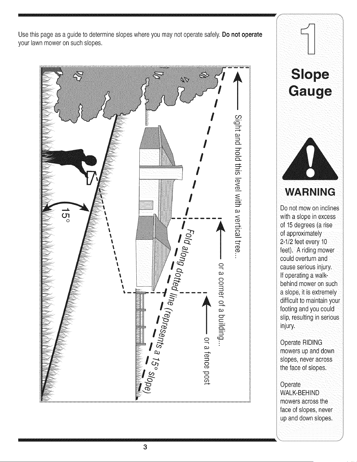
Slope Operation:
Slopesare a majorfactor relatedto loss of controland
tip-overaccidentswhichcan resultin severeinjuryor
death.All slopesrequireextracaution.If youcannot
backupthe slopeor if youfeel uneasyon it, do notmow
it.
Foryour safety,usethe slopegaugeincludedas partof
thismanualto measureslopesbeforeoperatingthis unit
ona slopedor hillyarea. Ifthe slopeis greaterthan 15
degreesas shownon theslopegauge,do notoperate
thisunit onthatareaor seriousinjurycouldresult.
DO:
1. Mowupanddownslopes,notacross. Exercise
extremecautionwhenchangingdirectionon slopes.
2. Watchfor holes,ruts,bumps,rocks,or other hidden
objects.Uneventerraincouldoverturnthe machine.
Tallgrasscan hideobstacles.
3. Useslowspeed.Choosea low enoughspeed
settingso thatyouwill not haveto stopor shift while
onthe slope.Tiresmaylosetractiononslopeseven
thoughthe brakesarefunctioningproperly.Always
keepmachineingearwhengoingdown slopesto
takeadvantageof enginebrakingaction.
4. Followthe manufacturer'srecommendationsfor
wheelweightsor counterweightsto improvestability.
5. Useextracare withgrasscatchersorotherat-
tachments.Thesecanchangethe stabilityof the
machine.
6. Keepall movementon the slopesslowand gradual.
Do not makesuddenchangesin speedor direction.
Rapidengagementor brakingcouldcausethe front
of the machineto liftand rapidlyflip overbackwards
whichcouldcauseseriousinjury.
7. Avoidstartingor stoppingon a slope.If tireslose
traction,disengagethe blade(s)andproceedslowly
straightdownthe slope.
Do Not:
1. Do notturn on slopesunlessnecessary;then,turn
slowlyandgraduallydownhill,if possible.
2. Do not mowneardrop-offs,ditchesor embankments.
Themowercouldsuddenlyturnoverif a wheel is over
the edgeof a cliff, ditch,or if an edge cavesin.
3. Do nottry to stabilizethe machineby puttingyourfoot
onthe ground.
4. Do not usea grasscatcheron steep slopes.
5. Do not mowonwetgrass. Reducedtractioncould
causesliding.
6. Do not shiftto neutralandcoastdownhill.Over-speed-
ingmaycausethe operatorto losecontrolof the
machineresultingin seriousinjuryor death.
7. Do nottowheavypullbehindattachments(e.g.loaded
dumpcart, lawnroller,etc.)on slopesgreaterthan
5 degrees.Whengoingdown hill,the extra weight
tendsto pushthe tractorandmaycauseyou to loose
control.(e.g.tractormayspeedup, brakingand steer-
ingabilityarereduced,attachmentmayjack-knifeand
causetractorto overturn).
Towing:
1. Towonlywith a machinethat hasa hitchdesignedfor
towing.Donot attachtowedequipmentexceptat the
hitchpoint.
2. Followthe manufacturersrecommendationfor weight
limitsfor towedequipmentandtowingon slopes.
3. Neverallowchildrenor othersin or on towedequip-
ment.
4. Onslopes,the weightof the towedequipmentmay
causelossof tractionandlossof control.
5. Travelslowlyandallowextra distanceto stop.
6. Do not shiftto neutralandcoastdownhill.
6
Service
1. Neverrunanengineindoorsorina poorlyventilated
area. Engineexhaustcontainscarbonmonoxide,an
odorless,anddeadlygas.
2. Beforecleaning,repairing,or inspecting,makecertain
the blade(s)andall movingparts havestopped.
Disconnectthe sparkplugwireandgroundagainstthe
engineto preventunintendedstarting.
3. Periodicallycheckto makesurethe bladescometo
completestopwithinapproximately(5) five seconds
afteroperatingthe bladedisengagementcontrol.Ifthe
bladesdo notstop within thethis timeframe,yourunit
shouldbe servicedprofessionallyby anauthorized
MTDServiceDealer.
4. Checkbrakeoperationfrequentlyas it is subjectedto
wearduringnormaloperation.Adjustand serviceas
required.
5. Checkthe blade(s)andenginemountingboltsat
frequentintervalsfor propertightness.Also,visually
inspectblade(s)for damage(e.g.,excessivewear,
bent,cracked). Replacethe blade(s)with theoriginal
equipmentmanufacturer's(O.E.M.)blade(s)only,
listedinthis manual."Useof partswhich do not meet
the originalequipmentspecificationsmayleadto
improperperformanceandcompromisesafety!"
6. Mowerbladesaresharp.Wrapthe bladeor wear
gloves,anduseextracautionwhenservicingthem.
7. Keepallnuts, bolts,and screwstight to be surethe
equipmentis insafeworkingcondition.
8. Nevertamperwiththe safety interlocksystemor other
safetydevices.Checktheir properoperationregularly.
9. Afterstrikingaforeignobject,stop the engine,
disconnectthe sparkplugwire(s)andgroundagainst
the engine.Thoroughlyinspectthe machinefor any
damage.Repairthe damagebeforestartingand
operating.
10.Neverattemptto makeadjustmentsor repairsto the
machinewhilethe engineisrunning.
11.Grasscatchercomponentsand the discharge
coveraresubjectto wearanddamagewhich could
exposemovingpartsor allowobjectsto be thrown.
Forsafetyprotection,frequentlycheckcomponents
andreplaceimmediatelywithoriginalequipment
manufacturer's(O.E.M.)partsonly,listedinthis
manual."Useof parts which donot meetthe original
equipmentspecificationsmayleadto improper
performanceandcompromisesafety!"
12.Do notchangethe enginegovernorsettingsor
over-speedthe engine.Thegovernorcontrolsthe
maximumsafeoperatingspeedof the engine.
13.Maintainor replacesafetyandinstructionlabels,as
necessary.
14.Observeproperdisposallawsand regulationsfor
gas,oil,etc. to protecttheenvironment.
7
This symbol points
out important safety
instructions which, if
not followed, could
endangerthe personal
safety and/or property
of yourselfand others.
Read and follow all
instructions in this man-
ual before attempting to
operatethis machine.
Failureto comply with
these instructions may
result in personal injury.
When you see this
symbol.
HEED iTS WARNING
Your
Responsibility
Restrictthe use
of this power machine
to personswho read.
understand
and follow the warnings
and instructions
in this manual
Tractor
Use extreme care
whenhandling
gaso nelGasoline
extremely flammable
and the vapors are
explosive: Never fuel
machine indoors
or while the engine
is hot or running,
Extinguish cigarettes,
cigars, pipes, and
othersourcesof
ignitionl
NOTE: This Operators
Manual Coversa range
of produCtspecifications
for VariousmodelS:
Characteristics and
i
featuresdiscussed
and/or illustratedin
s manualmay not
applicable toall models:
MTD LLC reservesthe
right to change product
specifications, (Jesigns
and equipment without
notice and without incur-
i[ing obligatiOnl
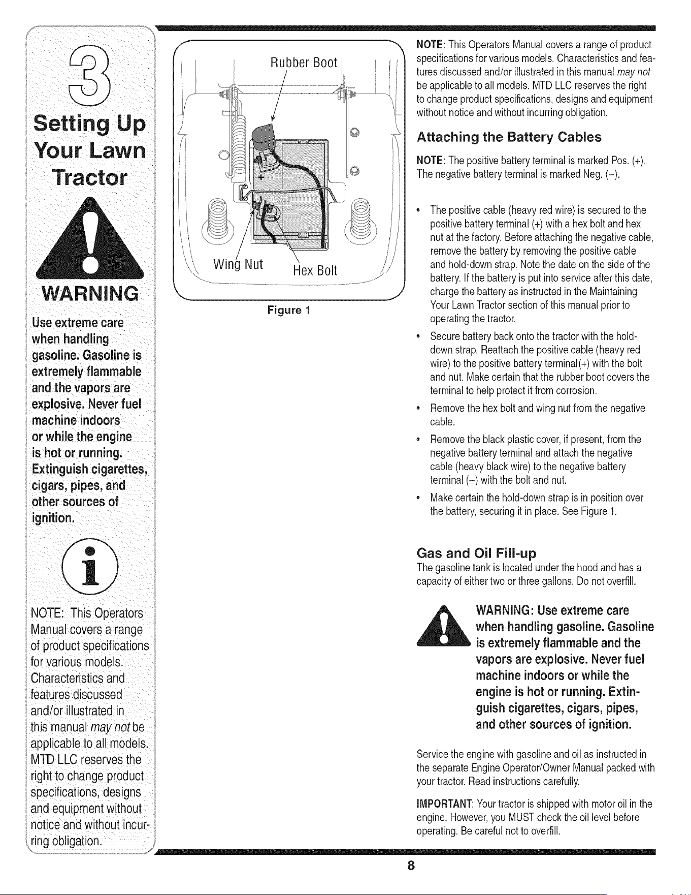
RubberBoot
Figure 1
NOTE:ThisOperatorsManualcoversa rangeof product
specificationsfor variousmodels.Characteristicsandfea-
turesdiscussedand/orillustratedinthis manualmaynot
beapplicableto all models.MTDLLCreservesthe right
to changeproductspecifications,designsandequipment
withoutnoticeandwithoutincurringobligation.
Attaching the Battery Cables
NOTE:Thepositivebatteryterminalis markedPos. (+).
Thenegativebatteryterminalis markedNeg.(-).
• Thepositivecable(heavyredwire) is securedto the
positivebatteryterminal(+)with a hexbolt andhex
nut at thefactory.Beforeattachingthe negativecable,
removethe batteryby removingthe positivecable
andhold-downstrap.Notethe dateon the sideof the
battery.Ifthe batteryis putinto serviceafter this date,
chargethe batteryas instructedin the Maintaining
YourLawnTractorsectionof this manualpriorto
operatingthetractor.
• Securebatterybackontothe tractorwiththe hold-
downstrap.Reattachthe positivecable (heavyred
wire)to the positivebatteryterminal(+)withthe bolt
andnut.Makecertainthat the rubberbootcoversthe
terminalto helpprotectit fromcorrosion.
• Removethehex boltandwing nutfromthe negative
cable.
• Removetheblackplasticcover,if present,from the
negativebatteryterminalandattachthe negative
cable(heavyblackwire)to the negativebattery
terminal(-) withthe bolt and nut.
• Makecertainthehold-downstrap is in positionover
the battery,securingit in place. See Figure1.
Gas and Oil Fill-up
Thegasolinetank is locatedunderthe hood and hasa
capacityof eithertwoor threegallons.Do notoverfill.
WARNING: Use extreme care
when handling gasoline. Gasoline
is extremely flammable and the
vapors are explosive. Never fuel
machine indoors or while the
engine is hot or running. Extin-
guish cigarettes, cigars, pipes,
and other sources of ignition.
Servicethe enginewithgasolineandoil as instructedin
the separateEngineOperator/OwnerManualpackedwith
yourtractor.Readinstructionscarefully.
IMPORTANT:Yourtractoris shippedwith motoroil in the
engine.However,you MUSTcheckthe oil levelbefore
operating.Becarefulnotto overfill.
8
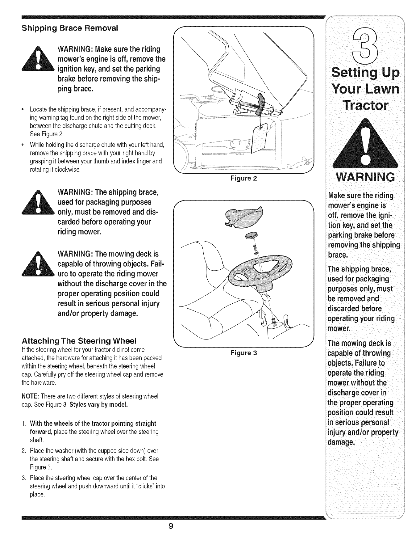
Shipping Brace Removal f
WARNING: Make sure the riding
mower's engine is off, remove the
ignition key, and set the parking
brake before removing the ship-
ping brace.
• Locatethe shippingbrace,ifpresent,andaccompany-
ingwarningtag foundon the rightside of the mower,
betweenthe dischargechuteand thecuttingdeck.
See Figure2.
• Whileholdingthe dischargechutewith yourleft hand,
removethe shippingbracewith your righthandby
graspingitbetweenyour thumbandindexfingerand
rotatingitclockwise.
WARNING: The shipping brace,
used for packaging purposes
only, must be removed and dis-
carded before operating your
riding mower.
WARNING: The mowing deck is
capable of throwing objects. Fail-
ure to operate the ridingmower
without the discharge cover in the
proper operating position could
result inserious personal injury
and/or property damage.
Attaching The Steering Wheel
Ifthe steeringwheelforyour tractordid notcome
attached,the hardwarefor attachingit hasbeenpacked
withinthe steeringwheel,beneaththe steeringwheel
cap.Carefullypry offthe steeringwheelcapand remove
the hardware.
NOTE:Therearetwodifferentstylesof steeringwheel
cap.SeeFigure3. Styles vary by model.
1. With the wheels of the tractor pointingstraight
forward, placethe steeringwheeloverthe steering
shaft.
2. Placethe washer(withthecuppedsidedown)over
the steeringshaftandsecurewiththe hex bolt.See
Figure3.
3. Placethe steeringwheelcap overthe centerof the
steeringwheelandpushdownwarduntilit"clicks"into
place.
Figure 2
Figure 3
TractOr
WARNING
Make sure the riding
mower's engine is
off, remove the igni-
tion key, and set the
parking brake before
removingthe shipping
brace.
The shipping brace,
used for packaging
purposes only, must
be removed and
discarded before
operating your riding
mower.
The mowing deck is
capable of throwing
objects. Failureto
operate the riding
mower without the
discharge cover in
the proper operating
position could result
in serious personal
injury and/or property
damage.
9
WARNING
Before operatingthis
machine,makesure
the seat is engaged in
the seat stop; stand
behindthemachine
andpu,backonseat
fu,yengaged
intostop:
NOTE: Forsh pping rea:
s0nsl Seatsareeither
fastenedto the tractor
seat's pivot braCketWitt
a plastiCtie, or mounted
backward to the pivot
bracket. In either case;
free the seat form its
shipping p0sition and
remove the two Box
screws (or knobsion
models so equipped)
from thebottom of seat
before proceedingwith
applicable instructions:
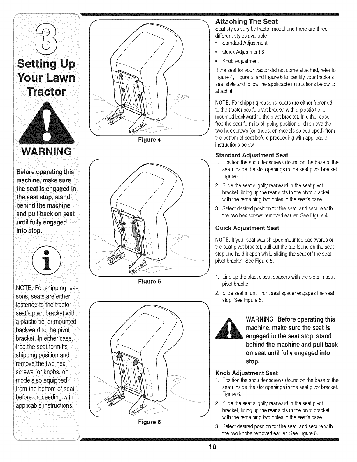
Attaching The Seat
Seatstylesvarybytractormodeland thereare three
differentstylesavailable:
• StandardAdjustment
• QuickAdjustment&
• KnobAdjustment
If the seatfor yourtractordid notcomeattached,referto
Figure4, Figure5, and Figure6 to identifyyourtractor's
seatstyleandfollowthe applicableinstructionsbelowto
attachit.
Figure 4
NOTE:Forshippingreasons,seatsare eitherfastened
to the tractorseat'spivotbracketwith a plastictie,or
mountedbackwardto the pivotbracket.Ineithercase,
freethe seatformitsshippingpositionand removethe
twohex screws(or knobs,on modelsso equipped)from
the bottomof seatbeforeproceedingwithapplicable
instructionsbelow.
Standard Adjustment Seat
1. Positionthe shoulderscrews(foundonthe baseof the
seat)insidetheslotopeningsinthe seatpivotbracket.
Figure4.
2. Slidethe seatslightlyrearwardin the seat pivot
bracket,liningupthe rearslots inthe pivot bracket
withthe remainingtwo holesin the seat'sbase.
3. Selectdesiredpositionforthe seat,andsecurewith
the twohex screwsremovedearlier.SeeFigure4.
Quick Adjustment Seat
NOTE:Ifyour seatwasshippedmountedbackwardson
the seatpivotbracket,pulloutthe tab foundonthe seat
stopandholdit openwhileslidingthe seatoff the seat
pivotbracket.SeeFigure5.
Figure 5
1. Lineupthe plasticseatspacerswiththe slotsin seat
pivotbracket.
2. Slideseatinuntilfrontseatspacerengagesthe seat
stop.SeeFigure5.
WARNING" Before operating this
machine, make sure the seat is
engaged in the seat stop, stand
behind the machine and pull back
on seat until fully engaged into
stop.
Figure 6
Knob Adjustment Seat
1. Positionthe shoulderscrews(foundonthe baseof the
seat)insidetheslotopeningsinthe seatpivotbracket.
Figure6.
2. Slidethe seatslightlyrearwardin the seat pivot
bracket,liningupthe rearslots inthe pivot bracket
withthe remainingtwo holesin the seat'sbase.
3. Selectdesiredpositionforthe seat,andsecurewith
the twoknobsremovedearlier.SeeFigure6.
10
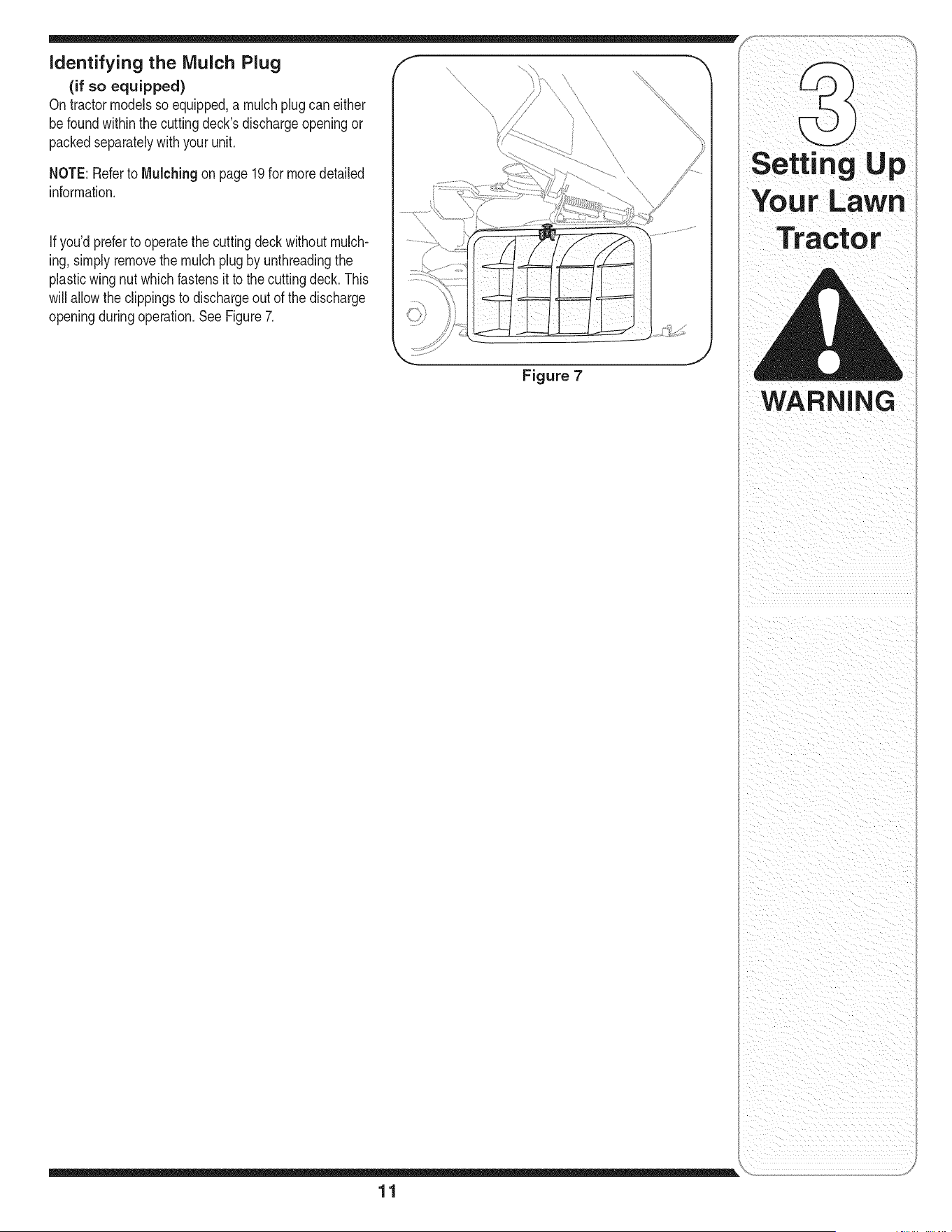
NOTE: Referto Mulching on page19for moredetailed
information.
Ifyou'dpreferto operatethe cuttingdeck withoutmulch-
ing, simplyremovethe mulchplugby unthreadingthe
plasticwing nutwhichfastensit to the cuttingdeck.This
will allowthe clippingsto dischargeout of the discharge
openingduringoperation.SeeFigure7.
Figure 7
LaWn
Tractor
WARNING
i i i i i i ii
ii i _iI_ ii
11
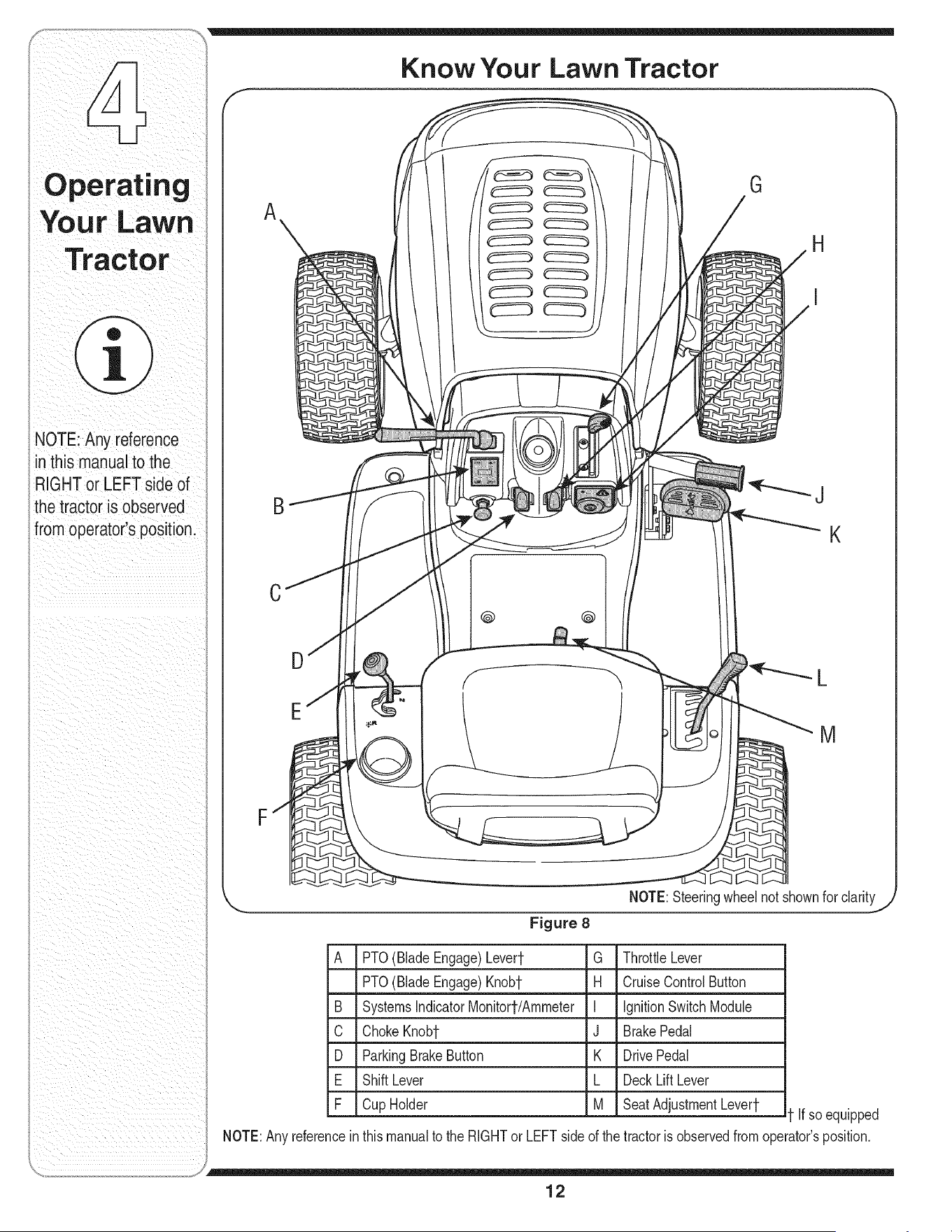
Know Your Lawn Tractor
NOTE: Any reference
in this manual to the
RIGHTor LEFT side of
the tractor is observed
from operator's position.
G
H
B
J
K
C
F
D
E
@ @
f" "_ L
M
NOTE:Steeringwheelnot shownfor clarity
Figure 8
A PTO(Blade Engage)Levert G ThrottleLever
PTO(BladeEngage)Knobt H CruiseControlButton
B SystemsIndicatorMonitort/Ammeter I IgnitionSwitchModule
C ChokeKnobt J BrakePedal
D ParkingBrakeButton K DrivePedal
E ShiftLever L DeckLiftLever
F CupHolder M SeatAdjustmentLevert
NOTE:Anyreferencein
If soequipped
thismanualto the RIGHTor LEFTside of the tractoris observedfromoperator'sposition.
12
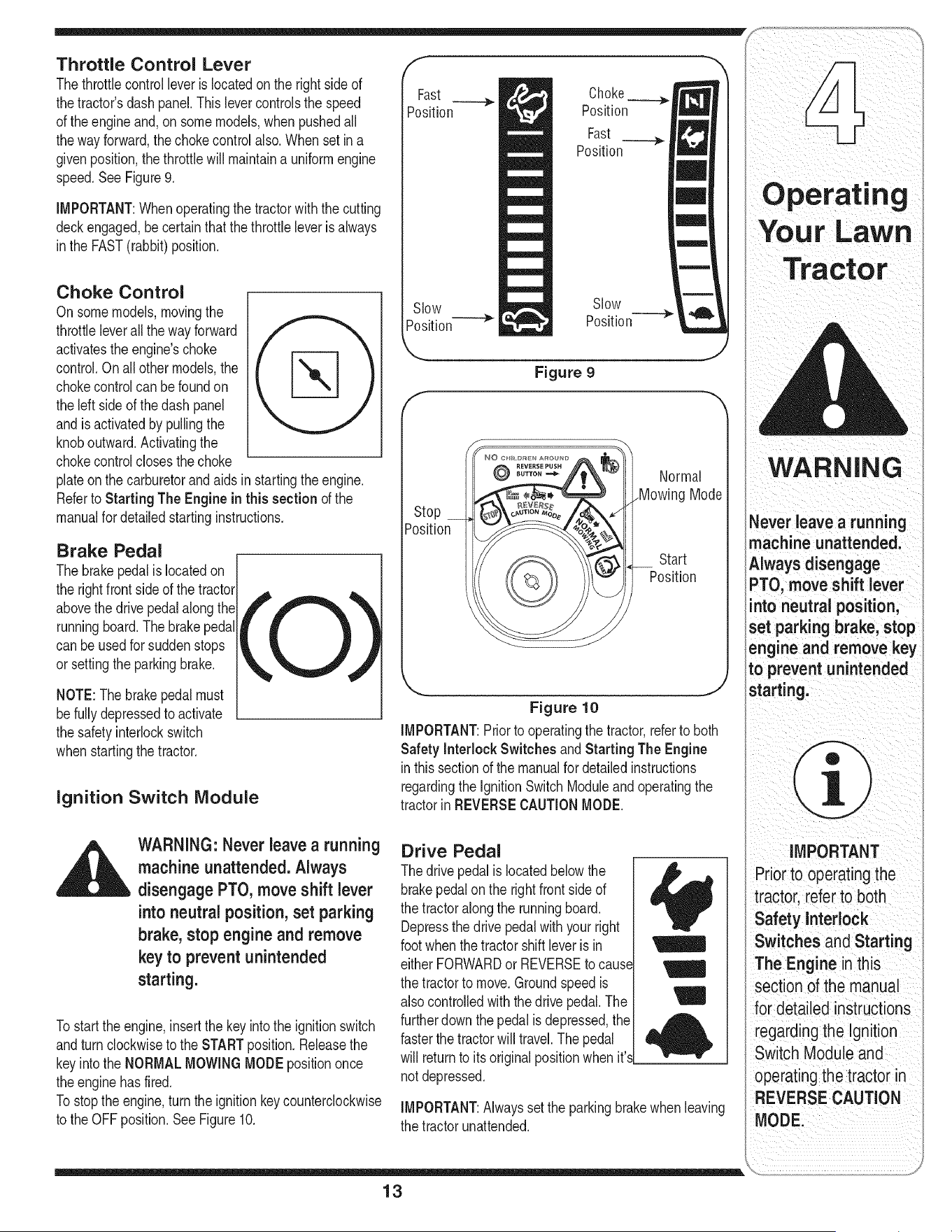
Throttle Control Lever
Thethrottlecontrolleveris locatedon the rightside of
thetractor'sdash panel.Thislevercontrolsthe speed
of the engineand,on somemodels,when pushedall
thewayforward,the chokecontrolalso.Whenset ina
givenposition,the throttlewill maintaina uniformengine
speed.SeeFigure9.
IMPORTANT:Whenoperatingthetractorwith the cutting
deckengaged,becertainthatthe throttleleveris always
inthe FAST(rabbit)position.
Choke Control
Onsomemodels,movingthe
throttleleverallthe wayforward
activatestheengine'schoke
control.Onall othermodels,the
chokecontrolcan befoundon
the leftside of thedash panel
andis activatedby pullingthe
knoboutward.Activatingthe
chokecontrolclosesthe choke
plateonthe carburetorandaids instartingthe engine.
Referto Starting The Enginein this sectionof the
manualfor detailedstartinginstructions.
Brake Pedal
[
The brakepedalislocatedon /
the rightfrontsideof the tractor_
abovethe drive pedalalongthe
runningboard.The brakepedal
can beusedfor suddenstops
or settingthe parkingbrake.
f
Fast
Position
Slow
Position
Choke
__-_).
Position
Fast
Position
Slow --->
Position
f
Position
Figure 9
Normal
Mode
Start
Position
NOTE:Thebrakepedal must
befullydepressedto activate
the safetyinterlockswitch
whenstartingthe tractor.
Ignition Switch Module
Figure 10
IMPORTANT:Priorto operatingthe tractor,referto both
Safety Interlock Switches andStarting The Engine
inthissectionof the manualfor detailedinstructions
regardingthe IgnitionSwitchModuleandoperatingthe
tractorinREVERSECAUTIONMODE.
WARNING: Never leave a running
machine unattended, Always
disengage PTO, move shift lever
into neutral position, set parking
brake, stop engine and remove
key to prevent unintended
starting,
Tostart theengine,insertthe key intothe ignitionswitch
andturnclockwiseto the STARTposition.Releasethe
keyintothe NORMALMOWINGMODEpositiononce
theenginehasfired.
Tostopthe engine,turn theignitionkey counterclockwise
to the OFFposition.SeeFigure10.
Drive Pedal
The drivepedalis locatedbelowthe
brakepedalon the rightfront side of
the tractoralongthe runningboard.
Depressthe drivepedalwithyourright
footwhenthe tractorshift leveris in
either FORWARDor REVERSEtocaus_
the tractorto move.Groundspeedis
also controlledwiththe drivepedal.The
furtherdown thepedalis depressed,the
fasterthe tractorwill travel.Thepedal
will returnto itsoriginalpositionwhen it'._
notdepressed.
M
/
4
IMPORTANT:Alwayssetthe parkingbrakewhenleaving
the tractorunattended.
Operating
Your LaWn
ii?i?ii!:ii ¸C :L i!iiC !i ¸
WARNING
Never leave a running
machine unattended,
Always disengage
PTO, move shift lever
nto neutral position,
set Parking brake, stop
engine and remove key
to prevent unintended
starting:
IMPORTANT
PriortooReratingthe
tractor,refer to both
Safety interlock
Switches and Starting
The Engine in this
seCtion ofthe manual
for detailed instructions
i
regardingthe Ign tion
SwitCh ModUleand
operating the tractoi in
REVERSE CAUTION
MODE:
13
Tractor
ii_i_ii iii_ii iii_iII ii!iii_i__IIIi i_i
NOTE: The PTO (Blade
Engage) knob must be
in the disengaged (OFF)
position when starting
the engine, when
traveling in reverseand
ifthe operator leaves
the seat.
NOTE: The PTO (Blade
Engage) lever must be
in the disengaged (OFF)
3ositionwhen starting
the engine, when
traveling tn reverseand
if the operator leaves
the seat.
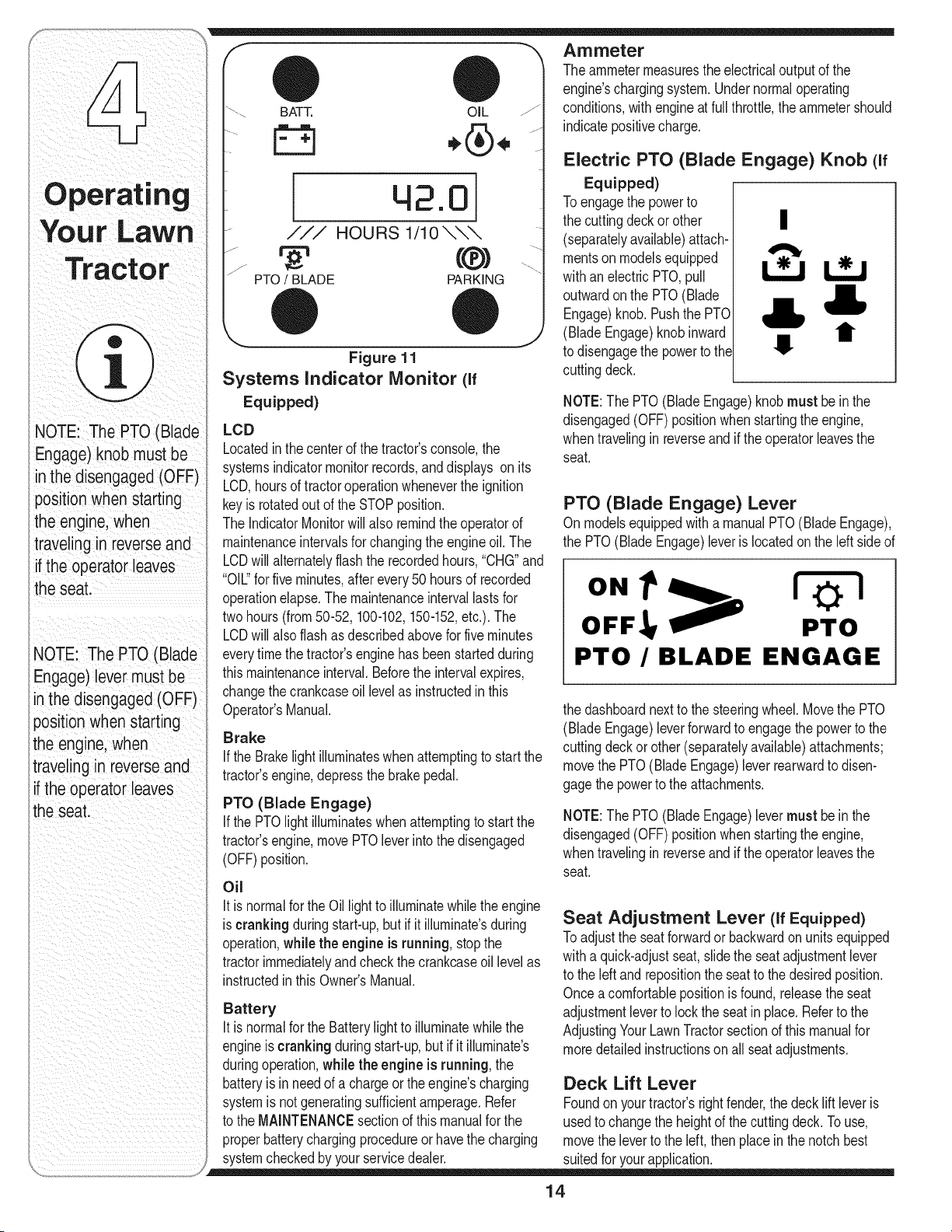
f "_ Ammeter
"-\ BATT. OIL /z
[ 42.0
/// HOURS 1/1 0 \\\
PTO / BLADE PARKING
,.® ®
Figure 11
Systems Indicator Monitor (if
Equipped)
J
LCD
Locatedinthe centerof the tractor'sconsole,the
systemsindicatormonitorrecords,anddisplays on its
LCD,hoursof tractoroperationwheneverthe ignition
keyis rotatedout of the STOPposition.
The IndicatorMonitorwill also remindthe operatorof
maintenanceintervalsfor changingthe engineoil. The
LCDwill alternatelyflashthe recordedhours,"CHG"and
"OIL"for five minutes,after every50 hoursof recorded
operationelapse.The maintenanceintervallastsfor
twohours(from50-52,100-102,150-152,etc.). The
LCDwill alsoflashas describedabovefor five minutes
everytimethe tractor'senginehasbeen startedduring
thismaintenanceinterval.Beforethe intervalexpires,
changethe crankcaseoil levelas instructedin this
Operator'sManual.
Brake
If the Brakelight illuminateswhenattemptingto start the
tractor'sengine,depressthe brakepedal.
PTO (Blade Engage)
if the PTOlightilluminateswhenattemptingto start the
tractor'sengine,movePTOleverintothe disengaged
(OFF)position.
Oil
It isnormalforthe Oil lightto illuminatewhilethe engine
iscranking duringstart-up,but ifit illuminate'sduring
operation,while the engine is running,stop the
tractorimmediatelyandcheckthe crankcaseoil levelas
instructedinthisOwner'sManual.
Battery
It is normalforthe Batterylightto illuminatewhilethe
engineis cranking duringstart-up,but if it illuminate's
duringoperation,while the engineis running,the
batteryis in needof a chargeorthe engine'scharging
systemis notgeneratingsufficientamperage.Refer
to the MAINTENANCEsectionof this manualfor the
properbatterychargingprocedureor havethe charging
systemcheckedby yourservicedealer.
Theammetermeasuresthe electricaloutput of the
engine'schargingsystem.Undernormaloperating
conditions,withengineat full throttle,the ammetershould
indicatepositivecharge.
Electric PTO (Blade Engage) Knob (If
Equipped)
Toengagethe powerto
the cuttingdeckor other |
(separatelyavailable)attach-
mentson modelsequipped
withanelectric PTO,pull
outwardonthe PTO(Blade
Engage)knob.Pushthe PTO
(BladeEngage)knobinward
to disengagethe powerto the
cuttingdeck.
NOTE:The PTO(BladeEngage)knobmustbe in the
disengaged(OFF) positionwhen startingthe engine,
whentravelingin reverseand if the operatorleavesthe
seat.
PTO (Blade Engage) Lever
Onmodelsequippedwitha manualPTO(Blade Engage),
the PTO(BladeEngage)leveris locatedonthe left sideof
ON 1z !
OFF !
PTO
PTO /BLADE ENGAGE
the dashboardnext to the steeringwheel.Movethe PTO
(BladeEngage)leverforwardto engagethe powerto the
cuttingdeckor other(separatelyavailable)attachments;
movethe PTO(BladeEngage)leverrearwardto disen-
gagethepowerto the attachments.
NOTE:The PTO(BladeEngage)levermust be in the
disengaged(OFF) positionwhen startingthe engine,
whentravelingin reverseand if the operatorleavesthe
seat.
Seat Adjustment Lever (If Equipped)
Toadjustthe seatforwardorbackwardon unitsequipped
witha quick-adjustseat,slidethe seatadjustmentlever
to the leftand repositionthe seatto the desiredposition.
Oncea comfortablepositionis found,releasethe seat
adjustmentleverto lockthe seatinplace.Referto the
AdjustingYourLawnTractorsectiond this manualfor
moredetailedinstructionson all seatadjustments.
Deck Lift Lever
Foundon yourtractor'srightfender,the deck lift leveris
usedto changethe heightof the cuttingdeck.To use,
movethe leverto the left,then placein the notchbest
suitedfor yourapplication.
14
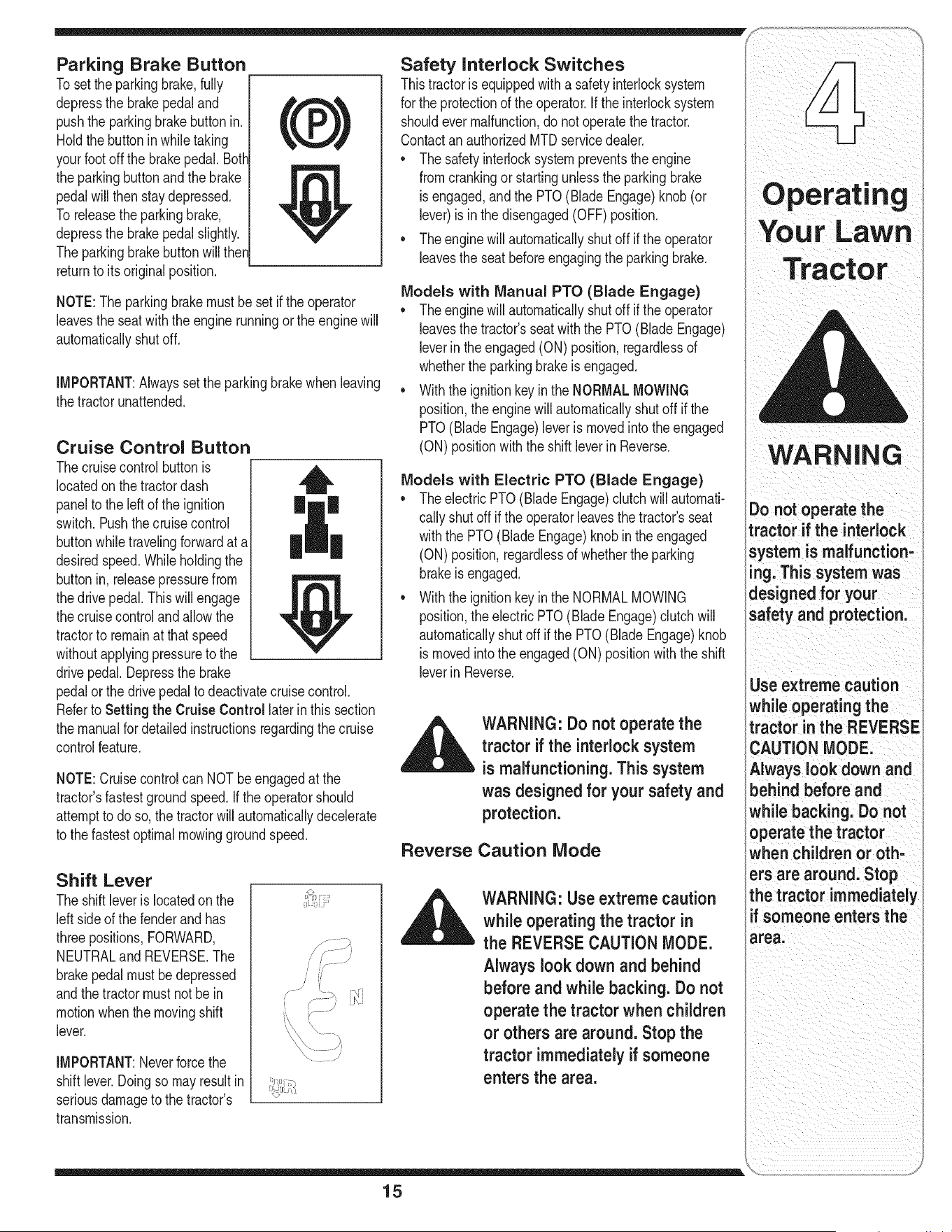
Parking Brake Button
Tosetthe parkingbrake,fully
depressthe brakepedaland
pushthe parkingbrakebutton in.
Holdthe buttoninwhiletaking
yourfootoffthe brakepedal.Both
the parkingbuttonandthe brake
pedalwill then staydepressed.
To releasethe parkingbrake,
depressthe brakepedalslightly.
The parkingbrakebuttonwill then
returnto itsoriginalposition.
NOTE:Theparkingbrakemust be set if the operator
leavesthe seatwiththe enginerunningor theengine will
automaticallyshutoff.
IMPORTANT:Alwaysset the parkingbrakewhen leaving
thetractor unattended.
Cruise Control Button
Thecruisecontrolbuttonis
locatedonthe tractordash
panelto the left of the ignition
switch.Pushthe cruisecontrol
buttonwhiletravelingforwardat a
desiredspeed.Whileholdingthe
buttonin, releasepressurefrom
thedrive pedal.Thiswill engage
thecruisecontrolandallowthe
tractorto remainat that speed
withoutapplyingpressureto the
drivepedal.Depressthe brake
pedalor the drivepedalto deactivatecruisecontrol.
Referto Setting the Cruise Control laterin this section
the manualfor detailedinstructionsregardingthecruise
controlfeature.
NOTE:Cruisecontrolcan NOTbeengagedat the
tractor'sfastestgroundspeed.If the operatorshould
attemptto doso,the tractorwill automaticallydecelerate
to the fastestoptimalmowinggroundspeed.
Shift Lever
The shiftleverislocatedon the
leftside of the fenderand has
threepositions,FORWARD,
NEUTRALand REVERSE.The
brakepedalmust bedepressed
andthe tractormustnot bein
motionwhenthe movingshift
lever.
IMPORTANT:Neverforcethe
shift lever.Doingso mayresultin
seriousdamageto the tractor's
transmission.
Safety Interlock Switches
Thistractorisequippedwitha safetyinterlocksystem
for the protectionof the operator.Ifthe interlocksystem
shouldevermalfunction,do notoperatethe tractor.
Contactan authorizedMTDservicedealer.
• The safetyinterlocksystempreventsthe engine
fromcrankingorstartingunlessthe parkingbrake
isengaged,and the PTO(Blade Engage)knob (or
lever)is in the disengaged(OFF)position.
• The enginewill automaticallyshutoff if the operator
leavesthe seatbeforeengagingtheparkingbrake.
Models with Manual PTO (Blade Engage)
• The enginewill automaticallyshutoff if the operator
leavesthe tractor'sseatwiththe PTO(Blade Engage)
leverin the engaged(ON) position,regardlessof
whetherthe parkingbrakeis engaged.
• Withthe ignitionkey in the NORMALMOWING
position,the enginewill automaticallyshut off if the
PTO(BladeEngage)leveris movedinto theengaged
(ON)positionwiththe shift leverinReverse.
Models with Electric PTO (Blade Engage)
• The electricPTO(BladeEngage)clutchwillautomati-
callyshutoff if the operatorleavesthetractor'sseat
withthe PTO(BladeEngage)knob inthe engaged
(ON)position,regardlessof whetherthe parking
brakeis engaged.
• Withthe ignitionkey in the NORMALMOWING
position,the electricPTO(BladeEngage)clutchwill
automaticallyshutoffif the PTO(BladeEngage)knob
is movedintothe engaged(ON) positionwiththe shift
leverin Reverse.
Reverse
WARNING: Do not operate the
tractor if the interlock system
is malfunctioning, This system
was designed for your safety and
protection.
Caution Mode
WARNING: Use extreme caution
while operating the tractor in
the REVERSE CAUTION MODE.
Always look down and behind
before and while backing. Do not
operate the tractor when children
or others are around, Stop the
tractor immediatelyif someone
enters the area.
15
WARNING
Do not operate the
tractor if the interlock
system is malfunction-
ing. This system was
designed for your
safety and protection.
Use extreme caution
while operating the
tractor inthe REVERSE
CAUTION MODE.
Always look down and
behind before and
while backing. Do not
operate the tractor
when children or oth-
ers are around. Stop
the tractor immediately
f someone enters the
area.
WARNING
Keep hands and feet
away from the dis-
charge opening of the
cutting deck.
Do not operate the
tractor if the interlock
system is malfunction-
ing. This system was
designedfor your
safety and protection.
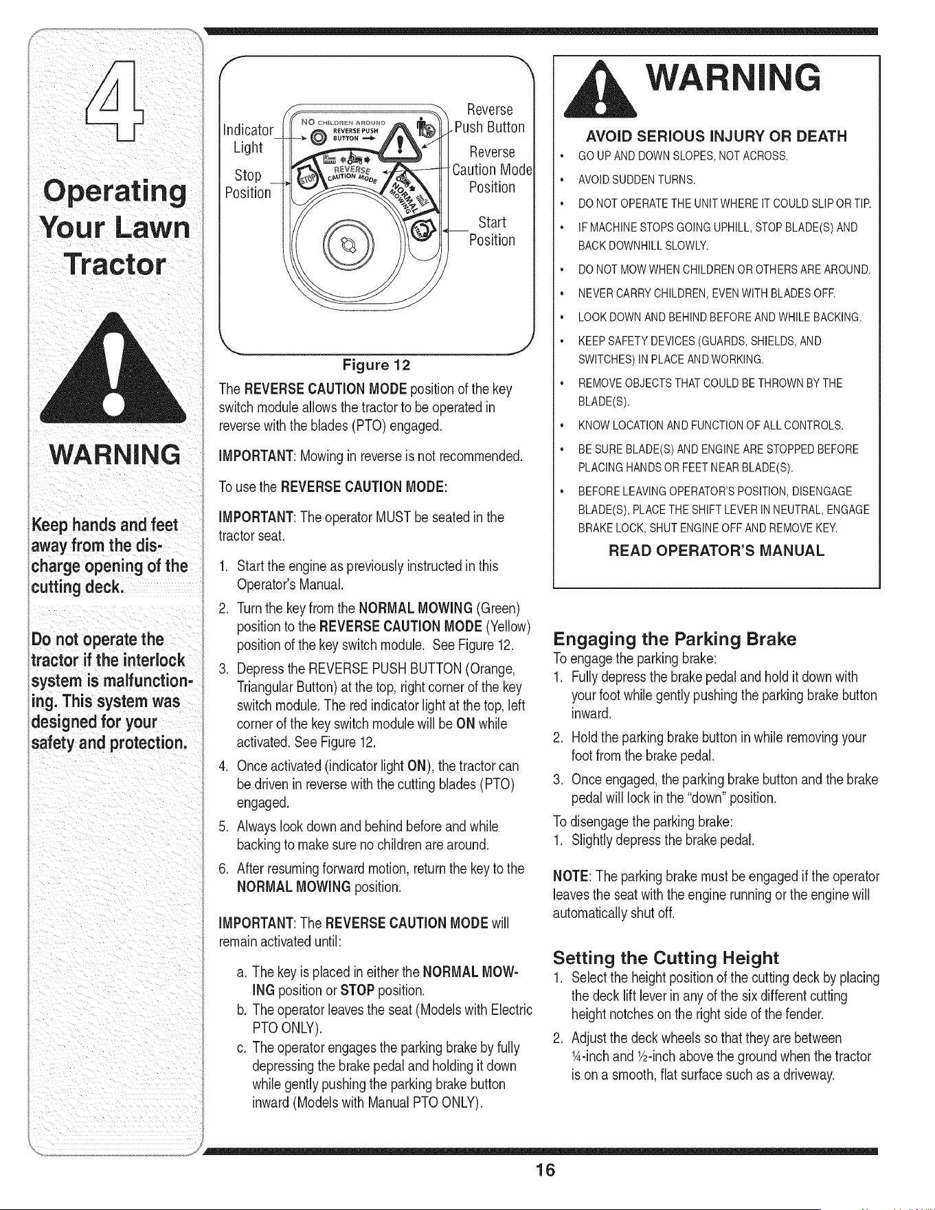
f
indicator
Light
Stop
Position
©
Reverse
.Push Button
Reverse
Caution Mode
Position
Start
Position
Figure 12
The REVERSECAUTIONMODE positionof the key
switchmoduleallowsthetractorto be operatedin
reversewiththe blades(PTO)engaged.
IMPORTANT:Mowingin reverseis not recommended.
Tousethe REVERSECAUTIONMODE:
IMPORTANT:TheoperatorMUSTbe seatedinthe
tractorseat.
1. Startthe engineas previouslyinstructedinthis
Operator'sManual.
2. Turnthe keyfromthe NORMALMOWING(Green)
positionto the REVERSECAUTIONMODE(Yellow)
positionof the keyswitchmodule. See Figure12.
3. Depressthe REVERSEPUSHBUTTON(Orange,
TriangularButton)at the top,rightcornerof the key
switchmodule.The redindicatorlight at thetop,left
cornerof the keyswitchmodulewill be ON while
activated.See Figure12.
4. Onceactivated(indicatorlightON), thetractorcan
bedrivenin reversewith the cuttingblades(PTO)
engaged.
5. Alwayslookdownand behindbeforeandwhile
backingto makesureno childrenare around.
6. Afterresumingforwardmotion,returnthe keyto the
NORMALMOWINGposition.
IMPORTANT:The REVERSECAUTIONMODEwill
remainactivateduntil:
a. Thekeyis placedin eitherthe NORMALMOW-
INGpositionor STOPposition.
b. Theoperatorleavesthe seat(ModelswithElectric
PTOONLY).
c. Theoperatorengagesthe parkingbrakeby fully
depressingthe brakepedalandholdingit down
whilegentlypushingthe parkingbrakebutton
inward(Modelswith ManualPTOONLY).
G
AVOID SERIOUS iNJURY OR DEATH
• GO UP AND DOWNSLOPES,NOT ACROSS.
• AVOID SUDDENTURNS.
• DO NOT OPERATETHEUNITWHERE IT COULDSLIP OR TIP.
• IF MACHINESTOPSGOINGUPHILL,STOP BLADE(S) AND
BACK DOWNHILLSLOWLY.
• DO NOT MOWWHEN CHILDRENOR OTHERSARE AROUND.
• NEVER CARRYCHILDREN,EVENWITH BLADESOFF.
• LOOK DOWNAND BEHINDBEFOREAND WHILEBACKING.
• KEEP SAFETYDEVICES(GUARDS,SHIELDS,AND
SWITCHES)IN PLACE ANDWORKING.
• REMOVEOBJECTSTHATCOULD BE THROWNBY THE
BLADE(S).
• KNOW LOCATIONAND FUNCTIONOF ALL CONTROLS.
• BE SUREBLADE(S) AND ENGINEARE STOPPEDBEFORE
PLACING HANDSOR FEET NEAR BLADE(S).
• BEFORE LEAVINGOPERATOR'SPOSITION,DISENGAGE
BLADE(S), PLACETHE SHIFTLEVER INNEUTRAL,ENGAGE
BRAKE LOCK,SHUT ENGINEOFF AND REMOVEKEY.
READ OPERATOR'S MANUAL
Engaging the Parking Brake
Toengagethe parkingbrake:
1. Fullydepressthe brakepedalandholdit downwith
yourfootwhilegentlypushingthe parkingbrakebutton
inward.
2. Holdthe parkingbrakebutton in while removingyour
footfromthe brakepedal.
3. Onceengaged,the parkingbrakebuttonand the brake
pedalwill lockin the "down"position.
Todisengagetheparkingbrake:
1. Slightlydepressthe brakepedal.
NOTE:Theparkingbrakemustbe engagedif the operator
leavesthe seatwiththe enginerunningor theengine will
automaticallyshutoff.
Setting the Cutting Height
1. Selectthe heightpositionof the cuttingdeckby placing
the decklift leverin anyof the sixdifferentcutting
heightnotchesonthe rightsideof the fender.
2. Adjustthe deckwheelsso thattheyare between
1A-inchandV2-inchabovethe groundwhen thetractor
is ona smooth,flat surfacesuch as a driveway.
16
,_ WARNING: Keep hands and feet Stopping the Engine
away from the discharge opening
of the cutting deck. ,_ WARNING: If you strike a foreign
NOTE:Thedeckwheelsarean anti-scalpfeatureof the A
object,
stop
the
engine,
discon-
deckandarenot designedto supportthe weightof the _ nect the spark plug wire(s) and
cuttingdeck. ground against the engine.
Referto Leveling the Deck onpage 20 of this manual Thoroughly inspect the machine
for moredetailedinstructionsregardingvariousdeck for any damage. Repair the
adjustments, damage before restarting and
Starting the Engine operating
1. Ifthe bladesareengaged,placethe PTO(Blade
_ WARNING: Do not operate the Engage)knob (orlever)in the disengaged(OFF)
tractor if the interlock system is position.
malfunctioning. This system was 2. Turnthe ignitionkeycounterclockwiseto the STOP
designed for your safety and position.
protection. 3. Removethe keyfromthe ignitionswitchto prevent
unintendedstarting.
NOTE:Referto theTRACTORSET-UPon page8 of this
manualfor Gasolineand Oil fill-up instructions. Driving The Tractor
1. Insertthe tractorkeyintothe ignitionswitch.
2. Placethe PTO(BladeEngage)knob(or lever)in the A_ WARNING: Avoid sudden starts,
disengaged(OFF) position. _ ex-cessive speed and sudden
3. Engagethe tractor'sparkingbrake, stops.
4. Activatethe chokecontrol.
5. Turnthe ignitionkey clockwiseto the STARTposition. WARNING: Do not leave the seat
Afterthe enginestarts,releasethe key.Itwill returnto of the tractor without first placing
the ON position, the PTO (Blade Engage) knob (or
lever) in the disengaged (OFF)
IMPORTANT:DoNOTholdthe keyin the STARTposi-
tionfor longerthanten secondsat a time.Doingso may position, depressing the brake
causedamageto your engine'selectricstarter, pedal and engaging the parking
brake, if leaving the tractor
6. Afterthe enginestarts,deactivatethechokecontrol
andplacethe throttlecontrolinthe FASTposition, unattended, also turn the ignition
key off and remove the key.
NOTE:Do NOTleavethe chokecontrolonwhile operat-
ingthe tractor.Doingso will resultina "rich"fuel mixture 1. Depressthe brakepedalto releasethe parkingbrake
andcausethe engineto runpoorly, andletthe pedalup.
2. Movethe throttleleverintothe FAST(rabbit)position.
IMPORTANT:Do NOTuse the shiftleverto changethe
directionof travelwhenthetractoris in motion.Always
usethe brakepedalto bringthe tractorto acomplete
stopbeforeshifting.
3. Tomoveforward,placethe shift leverinthe FOR-
WARDposition,thenslowlydepressthe drivepedal
untilthe desiredspeedisachieved.
Operating
Your LaWn
WARNING
if you strike a foreign
object, stop the
engine, disconnect
the spark plug wire(s)
and ground against
the engine. Thoroughly
inspectthe machine
for any damage. Repair
:he damage before
restarting and operat-
ing.
Avoid sudden starts,
ex-cessive speed and
sudden stops.
Do not leave the seat
of the tractor without
first placingthe PTO
(Blade Engage) knob
(or lever) in the disen-
gaged (OFF) position,
depressing the brake
pedal and engaging
the parking brake, if
leaving the tractor
unattended, also turn
the ignition key off and
remove the key.
17
Operating
Your Lawn
WARNING
Do not mow on inclines
with a slope in excess
of 15 degrees (a rise
of approximately 2-1/2
feet every 10feet). The
tractor could overturn
and cause serious
injury.
To help avoid blade
contact or a thrown
object injury, keep
bystanders, helpers,
children and pets at
least 75 feet from the
machine while it is in
operation. Stop ma=
chine if anyone enters
the area.
4. Tomovein reverse,placethe shiftleverinthe
REVERSEposition,checkthat thearea behindis
clearthen slowlydepressthe drivepedal.
Driving On Slopes
Referto the SLOPEGAUGEon page3 to help deter-
mineslopeswhereyou mayoperatethe tractorsafely.
_ WARNING" Do not mow on
inclineswith a slope in excess
of 15 degrees (a rise of approxi-
mately 2-1/2 feet every 10feet).
The tractor could overturn and
cause serious injury.
• Mowup and downslopes,NEVERacross.
• Exerciseextremecautionwhenchangingdirection
on slopes.
• Watchfor holes,ruts,bumps,rocks,or otherhidden
objects.Uneventerraincouldoverturnthe machine.
Tallgrasscan hideobstacles.
• Avoidturnswhendrivingona slope. If a turn must
be made,turn downthe slope.Turningup a slope
greatlyincreasesthechanceof a roll over.
• Avoidstoppingwhendrivingupa slope.If it is
necessaryto stopwhiledrivingup a slope, startup
smoothlyandcarefullyto reducethe possibilityof
flippingthe tractoroverbackward.
Setting The Cruise Control
1. Placethe shiftleverin the FORWARDposition,
thenslowlydepressthedrive pedaluntil the desired
speedis achieved.
2. Lightlydepressthe cruisecontrolbutton.
3. Whilecontinuingto holdthe cruisebuttonin,liftyour
footfromthedrive pedal(youshouldfeelthe cruise
latchengage).
Onceengaged,the cruisecontrolbuttonandthedrive
pedalwill lockinthe "down"position,and the tractorwill
maintainthe sameforwardspeed.
NOTE:Cruisecontrolcan notbe engagedat the
tractor'sfastestgroundspeed.If the operatorshould
attemptto doso,the tractorwill automaticallydecelerate
to the fastestoptimalmowinggroundspeed.
Disengagethecruisecontrolusingoneof the following
methods:
1. Depressthe brakepedalto disengagethecruise
controlandstopthe tractor.
2. Lightlydepressthe drivepedal.
Tochangeto the reversedirectionwhenoperatingwith
cruisecontrol,depressthe brakepedalto disengagethe
cruisecontroland bringthe tractorto a completestop.
Thenplacethe shift leverin the REVERSEpositionand
depressthedrive pedal.
Engaging the Blades
Engagingthe PTO(BladeEngage)transferspowerto the
cuttingdeckor other(separatelyavailable)attachments.
Toengagethe blades,proceedas follows:
1. Movethe throttlecontrolleverto the FAST(rabbit)
position.
Models with Manual PTO
2. a. Graspthe PTO(BladeEngage)leverand pivotit all
the wayforwardinto theengaged(ON) position.
Models with Electric PTO
b. Pullthe PTO(BladeEngage)knoboutwardintothe
engaged(ON)position.
3. Keepthe throttleleverinthe FAST(rabbit)position
for the mostefficientuseof the cuttingdeck or other
(separatelyavailable)attachments
IMPORTANT:The engine(onmodelswitha manualPTO)
orelectric PTOclutch(on modelswith an electricPTO)
will automaticallyshutoff ifthe PTOis engagedwith the
shift leverinpositionfor reversetravelwiththe ignition
keyinthe NORMALMOWINGposition.Referto Safety
InterlockSwitchesearlierinthissection.
Using the Deck Lift Lever
Toraisethe cuttingdeck,movethe deck lift leverto the
left, thenplaceit inthe notchbestsuitedfor yourapplica-
tion.Referto SettingThe CuttingHeightearlierinthis
section.
Mowing
_ ARNING: To help avoid blade
contact or a thrown object injury,
keep bystanders, helpers, children
and pets at least 75 feet from the
machine while it is in operation.
Stop machine if anyone enters the
area.
18
Thefollowinginformationwill behelpfulwhenusingthe
cuttingdeckwithyourtractor:
_ ARNING: Plan your mowing
pattern to avoid discharge of
materials toward roads, side-
walks, bystanders and the like.
Also, avoid discharging material
against a wall or obstruction
which may cause discharged
material to ricochet back toward
the operator.
• Do not mowat highgroundspeed,especiallyif a
mulchkit or grass collectoris installed.
• Forbest resultsit is recommendedthat the firsttwo
laps becutwiththe dischargethrowntowardsthe
center.Afterthefirst two laps, reversethedirectionto
throwthe dischargeto the outsidefor the balanceof
cutting.Thiswill givea betterappearanceto the lawn.
• Do notcut the grasstoo short.Shortgrass invites
weedgrowthandyellowsquicklyin dryweather.
• Mowingshouldalwaysbe donewith the engineat full
throttle.
Underheavierconditionsit may be necessaryto go
backoverthe cut areaa secondtimeto get a clean
cut.
• Do NOTattemptto mowheavybrushand weedsand
extremelytall grass.Yourtractoris designedto mow
lawns,NOTclearbrush.
• Keepthe bladessharpand replacethe bladeswhen
worn.Referto Cutting Blades inthe Maintaining
YourLawnTractorsectionof this manualfor proper
bladesharpeninginstructions.
Mulching (If Equipped)
Selectmodelscomeequippedwitha mulchkitwhich
incorporatesspecialblades,alreadystandardonthe
tractor,ina processof recirculatinggrass clippings
repeatedlybeneaththe cuttingdeck.Theultra-fine
clippingsarethenforcedbackintothe lawnwherethey
actas a naturalfertilizer.
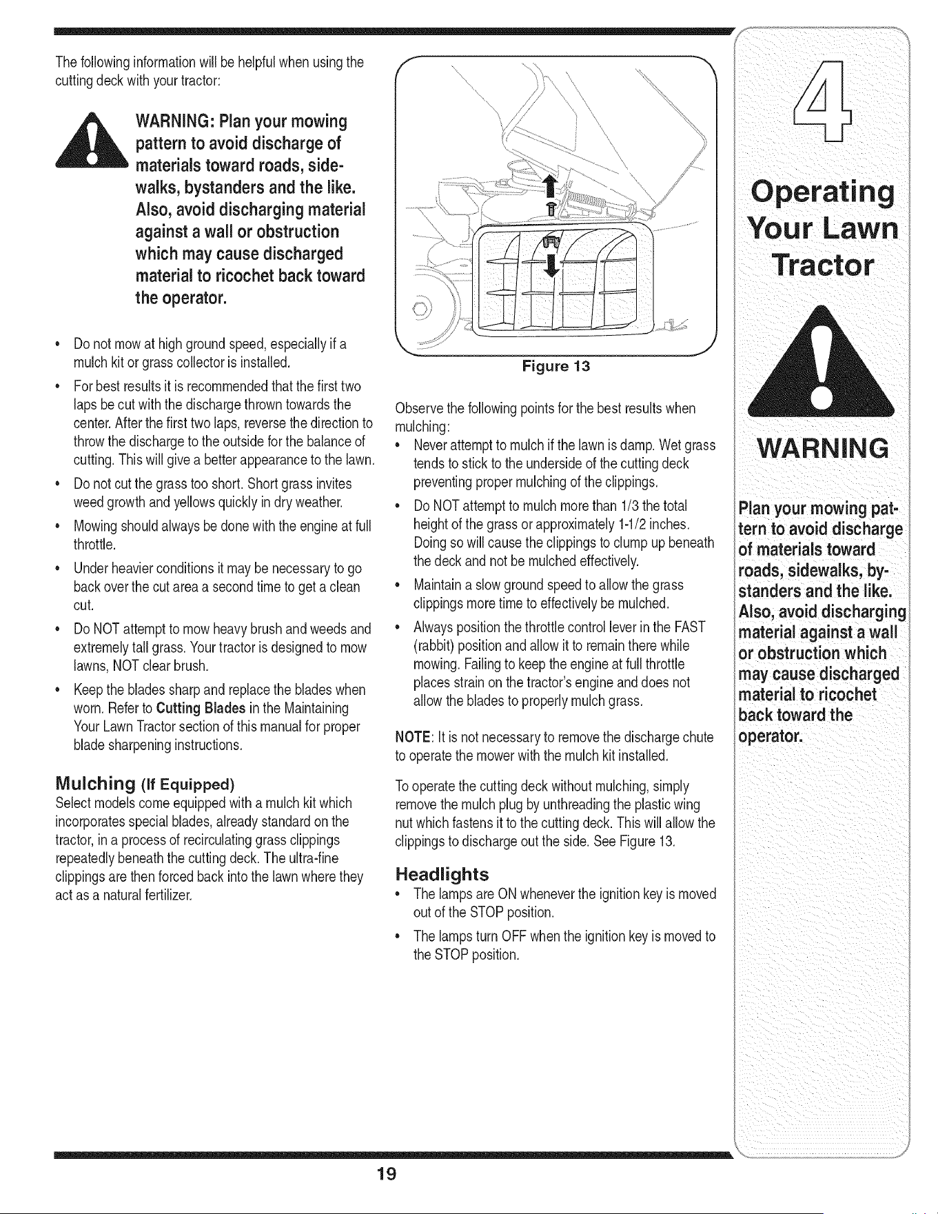
Figure 13
Observethe followingpointsfor the bestresultswhen
mulching:
• Neverattemptto mulchif the lawnis damp.Wetgrass
tendsto stickto the undersideof the cuttingdeck
preventingpropermulchingof the clippings.
Do NOTattemptto mulchmorethan 1/3 thetotal
heightof the grassorapproximately1-1/2inches.
Doingsowill causethe clippingsto clumpupbeneath
thedeckandnot be mulchedeffectively.
• Maintaina slowgroundspeedto allow the grass
clippingsmoretimeto effectivelybemulched.
• Alwayspositionthethrottlecontrolleverin the FAST
(rabbit)positionandallow it to remainthere while
mowing.Failingto keepthe engineat full throttle
placesstrainon thetractor'sengineanddoes not
allowthe bladesto properlymulch grass.
NOTE:It is notnecessaryto removethe dischargechute
to operatethe mowerwiththe mulchkitinstalled.
Tooperatethe cuttingdeck withoutmulching,simply
removethe mulchplugby unthreadingthe plasticwing
nutwhichfastensit to the cuttingdeck.This will allowthe
clippingsto dischargeoutthe side.SeeFigure13.
Headlights
• Thelampsare ONwheneverthe ignitionkeyis moved
outof the STOPposition.
• Thelampsturn OFFwhenthe ignitionkeyismovedto
theSTOPposition.
19
i ii i i ii iiiii iiii _I
0 perat ing
Your LaWn
WARNING
Plan your mowing pat-
tern to avoid discharge
of materials toward
roads, sidewalks, by-
standers and the like.
Also, avoid discharging
_aterial against a wall
_r obstruction which
may cause discharged
aterial to ricochet
back toward the
operator.
Tract
Novor tte ptto
make any adjust:
merits while the
i
engine isrunning,
!
except where speci,
fled in the operator's
manual:
NOTE: Check the
tractor's tire pressure
i before performing
any deck leveling
adjustments. Refer to
Tires on page 26 for
information regarding
tire pressure.
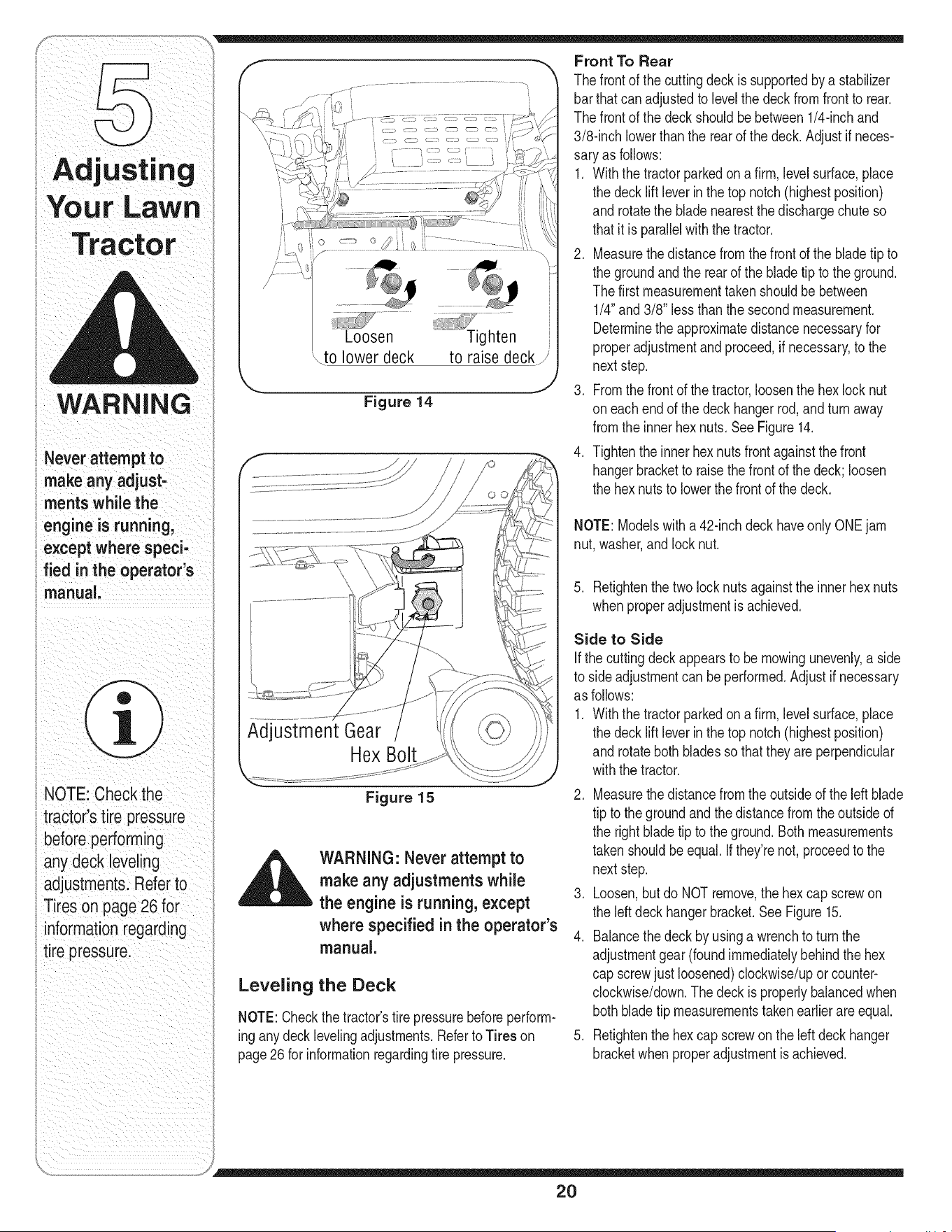
Loosen........... _ghten
\to lower deck to raise deck/
k,,._. .j
Figure 14
Front To Rear
Thefrontof the cuttingdeckissupportedbya stabilizer
barthatcanadjustedto levelthe deckfromfrontto rear.
Thefrontof the deckshouldbebetween1/4-inchand
3/8-inchlowerthanthe rearof the deck.Adjustif neces-
saryas follows:
1. Withthe tractorparkedon a firm,levelsurface,place
the deckliftleverinthe top notch(highestposition)
androtatethe bladenearestthe dischargechute so
thatitis paraIMwiththe tractor.
2. Measurethe distancefromthe frontofthe bladetip to
the groundandthe rearof the bladetip to the ground.
Thefirst measurementtakenshouldbebetween
1/4"and 3/8" lessthan thesecondmeasurement.
Determinethe approximatedistancenecessaryfor
properadjustmentandproceed,if necessary,to the
nextstep.
3. Fromthe frontof thetractor,loosenthe hexlocknut
oneachendof thedeck hangerrod,and turnaway
fromthe innerhex nuts.SeeFigure14.
4. Tightenthe innerhex nutsfrontagainstthe front
hangerbracketto raisethe front of the deck;loosen
the hexnutsto lowerthe frontof the deck.
NOTE:Modelswitha 42-inchdeck haveonlyONEjam
nut,washer,and lock nut.
Figure 15
_ ARNING: Never attempt to
make any adjustments while
the engine is running, except
where specified in the operator's
manual.
Leveling the Deck
NOTE:Checkthe tractor'stire pressurebeforeperform-
inganydeck levelingadjustments.Referto Tires on
page26 for informationregardingtire pressure.
5. Retightenthe two lock nutsagainstthe inner hexnuts
whenproperadjustmentis achieved.
Side to Side
If the cuttingdeck appearsto bemowingunevenly,a side
to sideadjustmentcan beperformed.Adjustif necessary
as follows:
1. Withthe tractorparkedon a firm,levelsurface,place
the decklift leverin the top notch(highestposition)
androtateboth bladesso thattheyareperpendicular
withthe tractor.
2. Measurethe distancefromthe outsideof the leftblade
tip to the groundandthe distancefromtheoutsided
the rightbladetip to theground.Bothmeasurements
takenshouldbeequal. Ifthey'renot,proceedto the
nextstep.
3. Loosen,butdo NOT remove,the hexcap screwon
the leftdeckhangerbracket.SeeFigure15.
4. Balancethe deckby usinga wrenchto turn the
adjustmentgear (foundimmediatelybehindthe hex
cap screwjust loosened)clockwise/upor counter-
clockwise/down.Thedeckis properlybalancedwhen
bothbladetip measurementstakenearlierareequal.
5. Retightenthe hex capscrewonthe left deck hanger
bracketwhenproperadjustmentis achieved.
20
_ ARNING: Never attempt to ad-
just the brakes while the engine is
running. Always disengage PTO,
move shift lever into neutral posi-
tion, stop engine and remove key
to prevent unintended starting.
Ifthe tractordoesnot cometo a completestopwhenthe
brakepedaliscompletelydepressed,or ifthe tractor's
rearwheelscan rollwiththe parkingbrakeapplied,the
brakeis inneedof adjustment,Thebrakedisccan be
foundon the rightsideof thetransmissioninthe rearof
the tractor.Adjustif necessaryas follows:
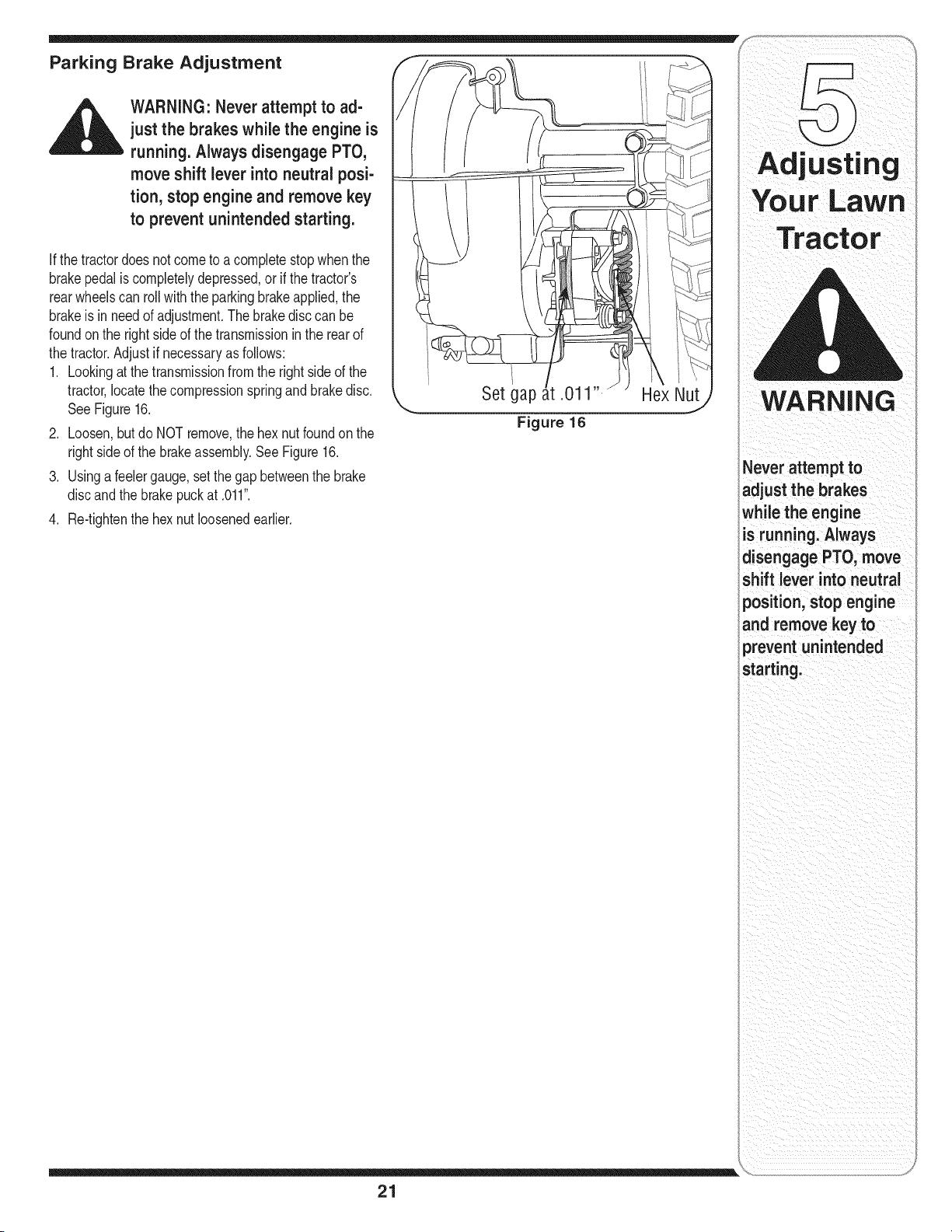
1. Lookingat thetransmissionfrom the right sideof the
tractor,locatethe compressionspringandbrakedisc.
See Figure16,
2. Loosen,but do NOTremove,the hex nutfoundon the
rightsideof the brakeassembly,See Figure16,
3. Usingafeelergauge,setthe gapbetweenthe brake
discandthe brakepuckat ,011",
4. Re4ightenthe hexnut loosenedearlier.
Set gap
Figure 16
Hex Nut
21
WARNING
Never attempt to
adjust the brakes
whilethe engine
is running. Always
disengage PTO, move
shift lever into neutral
position, stop engine
and remove key to
prevent unintended
starting.
Your LaWn
Before operating this
machine, make sure
the seat is engaged in
the seat stop, stand
behind the machine
and pull back on seat
until fully engaged into
Istop.
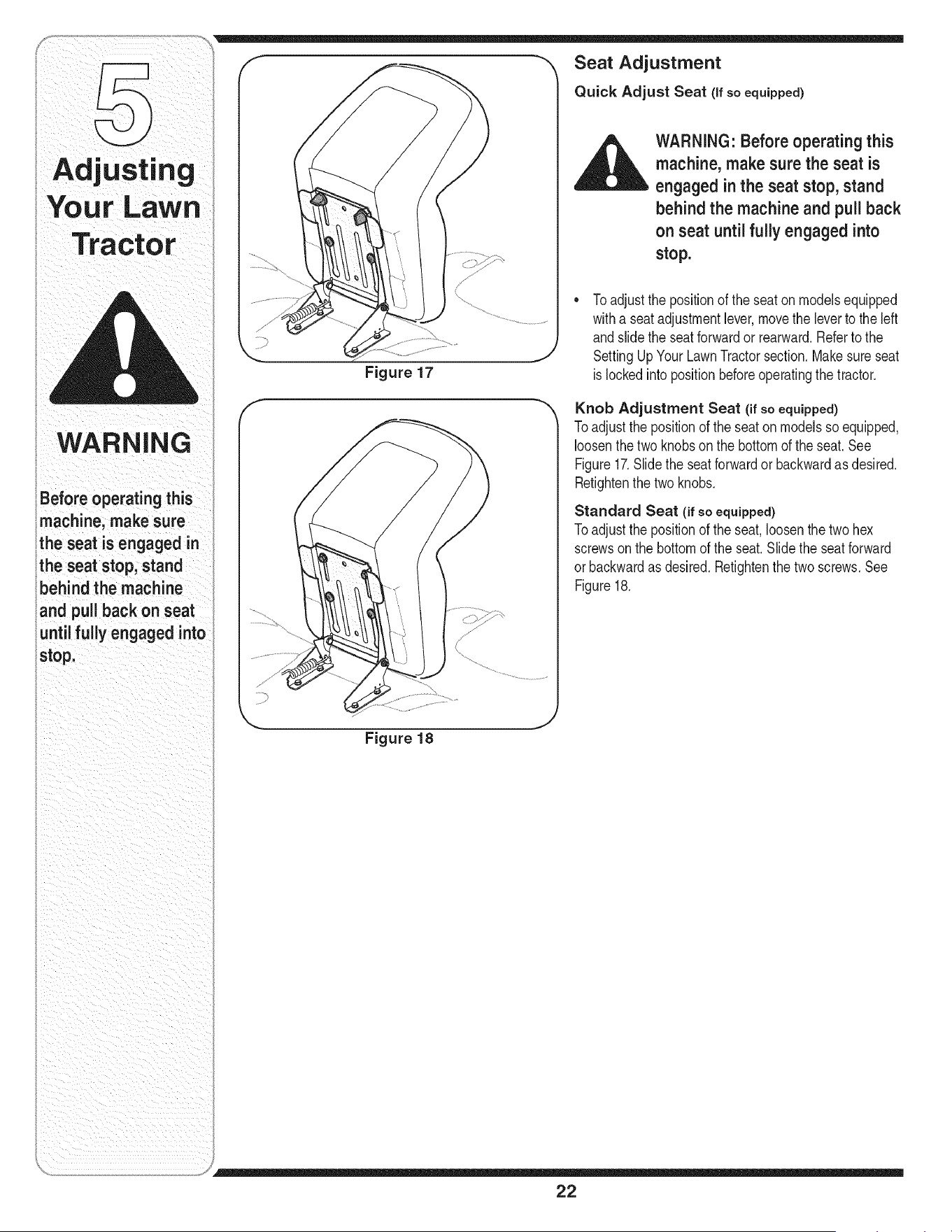
Seat Adjustment
Quick Adjust Seat (If so equipped)
,__ WARNING" Before operating this
machine, make sure the seat is
engaged in the seat stop, stand
behind the machine and pull back
on seat until fully engaged into
stop.
Figure 17
Toadjustthe positionof the seatonmodelsequipped
witha seatadjustmentlever,movethe leverto the left
andslidethe seatforwardor rearward.Referto the
SettingUp YourLawnTractorsection.Makesureseat
is lockedinto positionbeforeoperatingthe tractor.
Knob Adjustment Seat (if so equipped)
Toadjustthe positionof the seatonmodelsso equipped,
loosenthetwo knobson the bottomof the seat.See
Figure17.Slidethe seatforwardor backwardas desired.
Retightenthe two knobs.
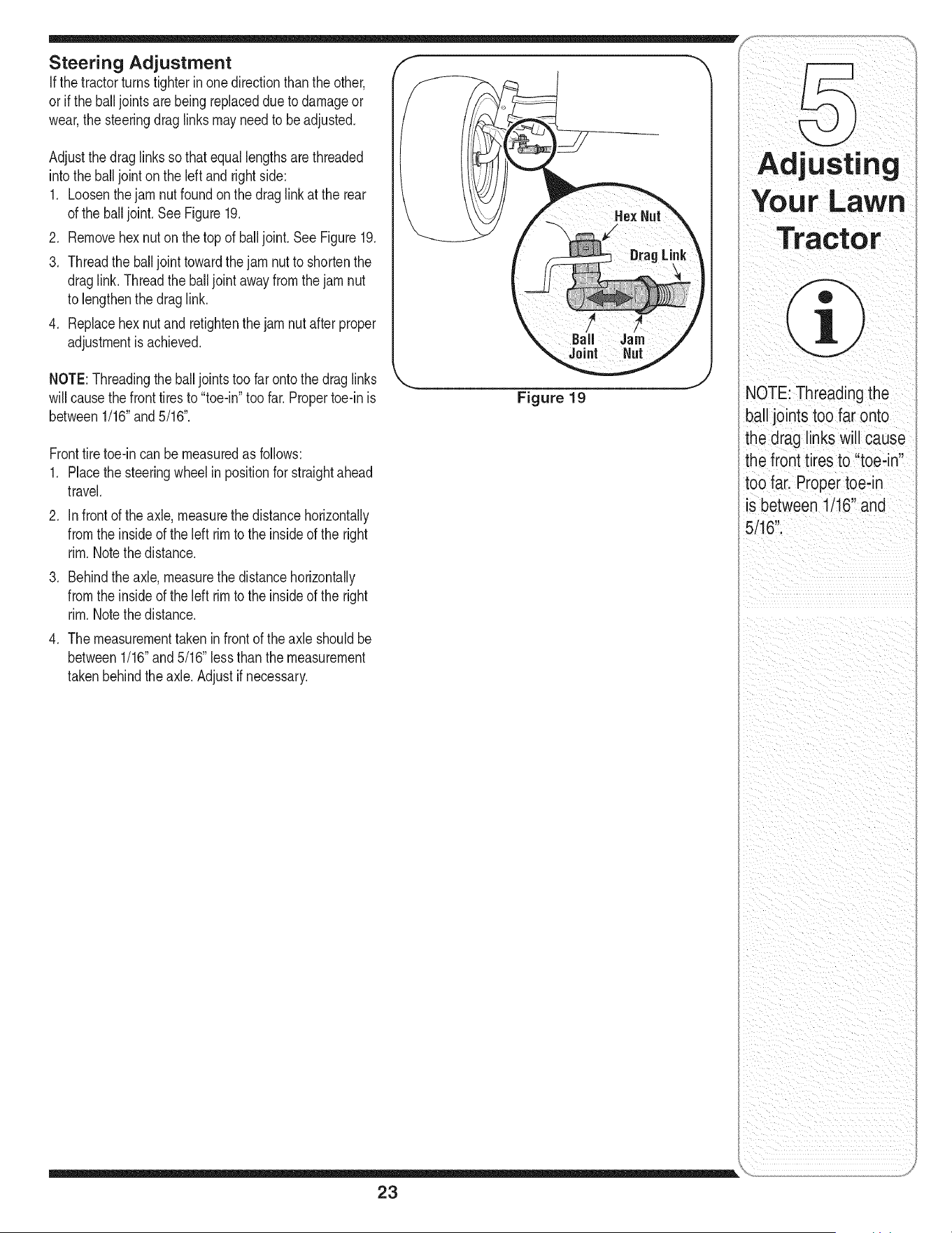
Standard Seat (if so equipped)
Toadjustthe positionof the seat,loosenthe twohex
screwsonthe bottomof the seat.Slidethe seatforward
orbackwardas desired,Retightenthe two screws,See
Figure18,
Figure 18
22
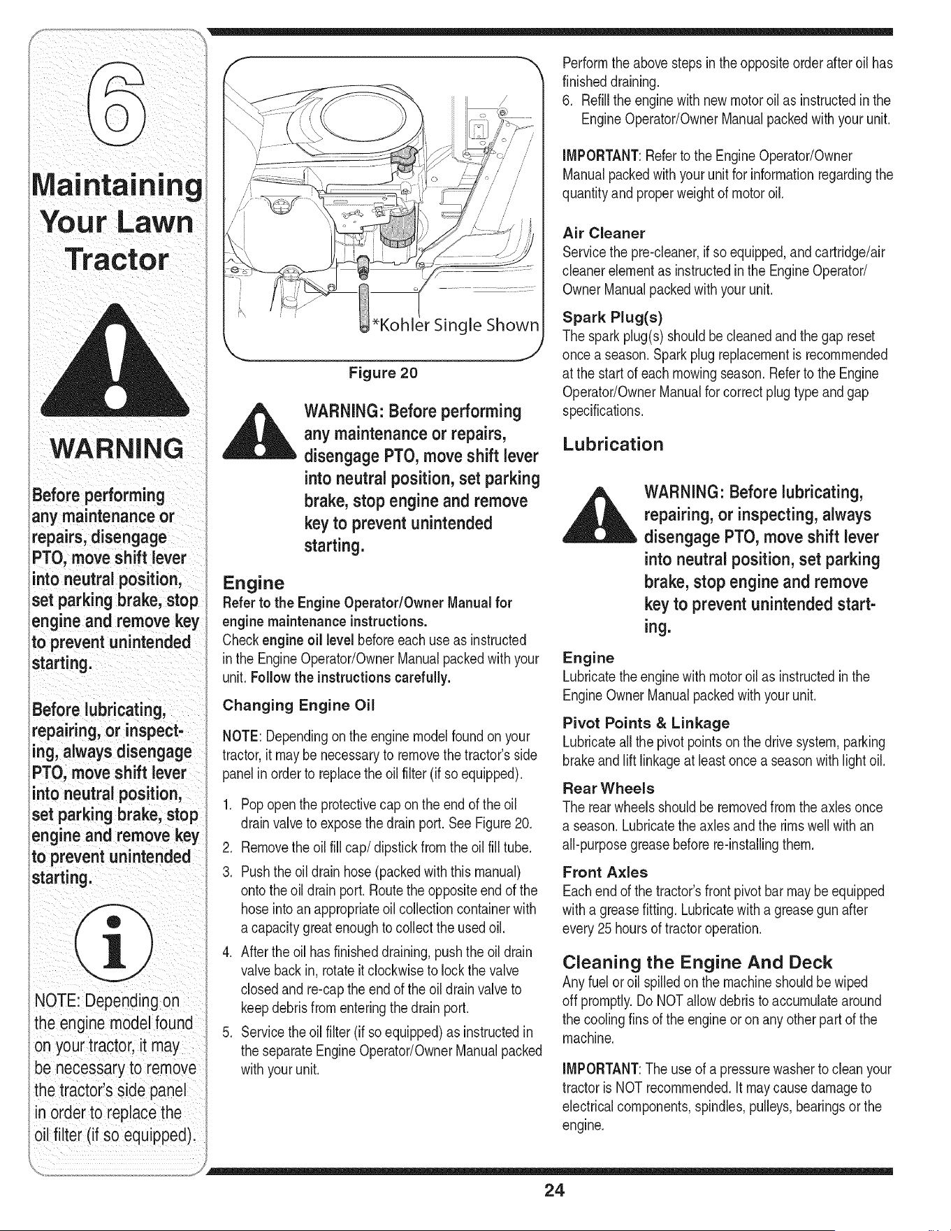
Adjustthe draglinksso thatequallengthsare threaded
intothe balljointon the left and rightside:
1. Loosenthejamnut foundon the drag linkat the rear
of the balljoint.See Figure19.
2. Removehex nuton thetop of balljoint.See Figure19.
3. Threadthe balljoint towardthejam nut to shortenthe
draglink.Threadtheballjointawayfromthejamnut
to lengthenthe drag link.
4. Replacehex nutand retightenthejamnut after proper
adjustmentis achieved.
NOTE:Threadingthe balljointstoo far ontothe drag links
will causethe fronttiresto "toe-in"too far. Propertoe-in is
between1/16"and5/16".
Figure 19
Fronttiretoe-in canbe measuredas follows:
1. Placethe steeringwheelin positionfor straightahead
travel.
2. Infrontof the axle, measurethe distancehorizontally
fromthe insideof the left rimto the insideof the right
rim.Notethe distance.
3. Behindthe axle,measurethe distancehorizontally
fromthe insideof the left rimto the insideof the right
rim.Notethe distance.
4. The measurementtakenin frontof the axle shouldbe
between1/16"and5/16"lessthanthe measurement
takenbehindthe axle.Adjustif necessary.
i / (¸¸¸¸¸:¸¸: i/ /
NOTEi Thleading the
ball joints too far ontO
the drag inks will Cause
the front tires to '!toe;in'
too faii Propertoe:in
is between 1/16'!and
ii i _iI_ ii
23
WARNING
any maintenance or
repairs, disengage
PTO, move shift lever
intoneutral position,
set parkingbrake, stop
engine and remove key
o preventu nintended
_tarting!
Before lubricatingi
repairing, or inspect,
ing, always disengage
PTOImove shift lever
into neutral position,
set parking brake, stop
engineandremovekey
to prevent unintended
startingl
NOTE:Dependingon
the engine model found
Onyour tractorl itmay
be necessary to remove
the tractor!s side panel
in OrdertO replace the
oil filter (if so equipped):
Figure 20
WARNING: Before performing
any maintenance or repairs,
disengage PTO, move shift lever
into neutral position, set parking
brake, stop engine and remove
key to prevent unintended
starting.
Engine
Referto the EngineOperator/Owner Manualfor
engine maintenance instructions.
Checkengineoil levelbeforeeachuseas instructed
inthe EngineOperator/OwnerManualpackedwithyour
unit.Follow the instructionscarefully.
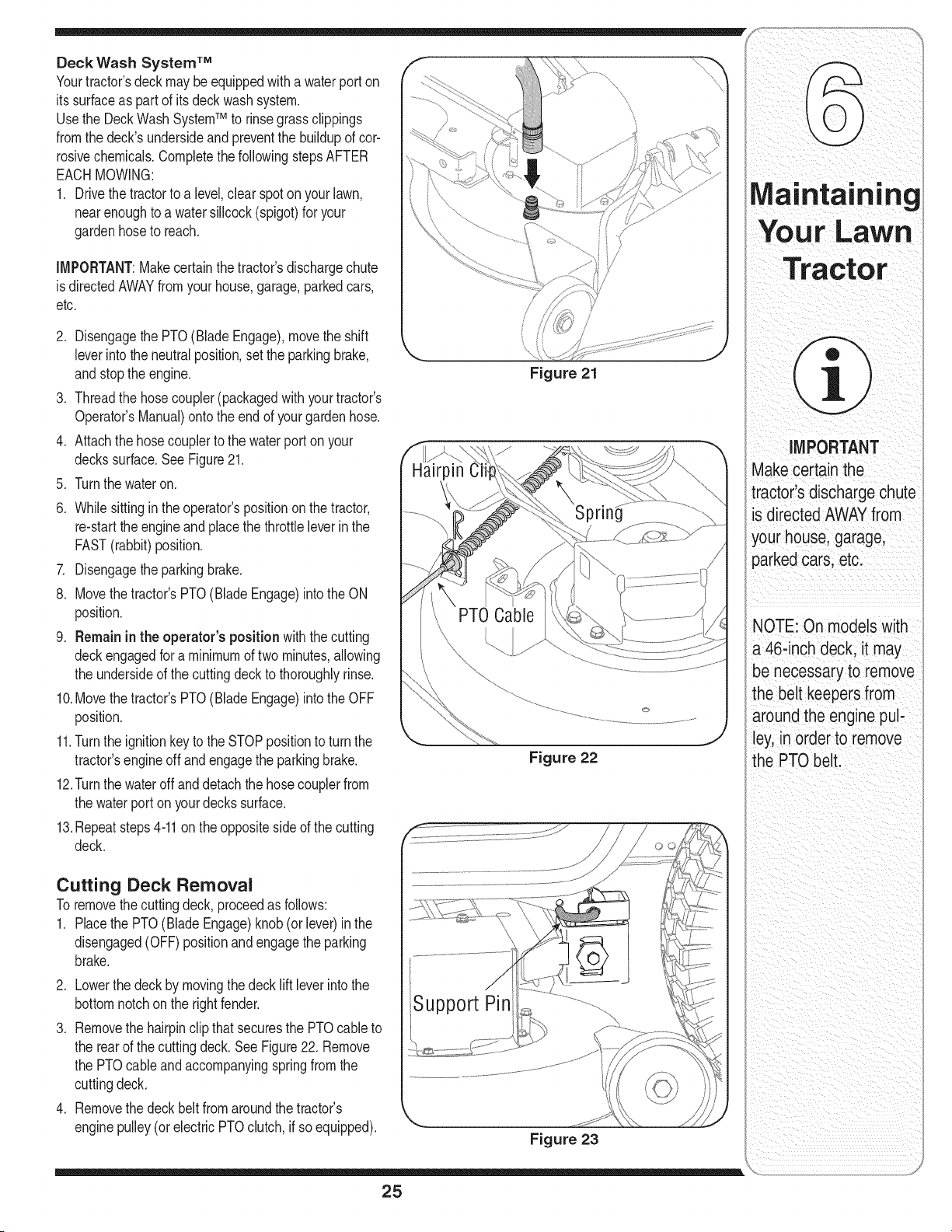
Changing Engine Oil
NOTE:Dependingonthe enginemodelfoundon your
tractor,it maybenecessaryto removethe tractor'sside
panelin order to replacethe oil filter (if so equipped).
1. Popopenthe protectivecap onthe endof the oil
drainvalveto exposethedrain port.See Figure20.
2. Removethe oil fill cap/dipstick from the oil fill tube.
3. Pushthe oildrainhose(packedwiththismanual)
ontothe oil drainport. Routethe oppositeendof the
hoseinto anappropriateoil collectioncontainerwith
a capacitygreatenoughtocollect theusedoil.
4. Afterthe oil has finisheddraining,pushtheoil drain
valvebackin, rotateit clockwiseto lockthe valve
closedand re-capthe end of the oil drainvalveto
keepdebrisfromenteringthedrain port.
5. Servicethe oilfilter (if soequipped)as instructedin
the separateEngineOperator/OwnerManualpacked
withyourunit.
Performthe abovestepsinthe oppositeorderafteroil has
finisheddraining.
6. Refillthe enginewith newmotoroil as instructedinthe
EngineOperator/OwnerManualpackedwithyour unit.
IMPORTANT:Referto the EngineOperator/Owner
Manualpackedwithyourunit for informationregardingthe
quantityandproperweightof motoroil.
Air Cleaner
Servicethe pre-cleaner,if soequipped,and cartridge/air
cleanerelementas instructedin the EngineOperator/
OwnerManualpackedwith your unit.
Spark Plug(s)
Thesparkplug(s)shouldbe cleanedand thegap reset
oncea season.Sparkplugreplacementis recommended
at the startof each mowingseason.Referto the Engine
Operator/OwnerManualfor correctplug type andgap
specifications.
Lubrication
_ ARNING: Before lubricating,
repairing, or inspecting, always
disengage PTO, move shift lever
into neutral position, set parking
brake, stop engine and remove
key to prevent unintended start-
ing.
Engine
Lubricatethe enginewithmotoroil as instructedin the
EngineOwnerManualpackedwith yourunit.
Pivot Points & Linkage
Lubricateall the pivotpoints on the drivesystem,parking
brakeand lift linkageat least oncea seasonwithlightoil.
Rear Wheels
The rearwheelsshouldbe removedfrom the axles once
a season.Lubricatethe axles and the rimswell with an
all-purposegreasebeforere-installingthem.
Front Axles
Eachendof the tractor'sfrontpivot bar may be equipped
witha greasefitting. Lubricatewith a greasegun after
every25 hoursof tractoroperation.
Cleaning the Engine And Deck
Anyfuel oroil spilledon the machineshouldbe wiped
off promptly.Do NOTallowdebristo accumulatearound
the coolingfinsof the engineor on any otherpart of the
machine.
IMPORTANT:The useof a pressurewasherto cleanyour
tractoris NOTrecommended.It maycause damageto
electricalcomponents,spindles,pulleys,bearingsor the
engine.
24
f
Deck Wash System TM ....
Yourtractor'sdeckmay be equippedwith a waterporton
its surfaceas part of itsdeckwashsystem.
Usethe DeckWashSystemTM to rinsegrassclippings
fromthe deck'sundersideand preventthe buildupof cor-
rosivechemicals.Completethe followingstepsAFTER
EACHMOWING:
1. Drivethe tractorto a level,dear spoton yourlawn,
nearenoughto a water sillcock(spigot)for your
gardenhoseto reach.
iMPORTANT:Makecertainthetractor'sdischargechute
is directedAWAYfromyourhouse,garage,parkedcars,
etc.
2. Disengagethe PTO(BladeEngage),movethe shift
leverintothe neutralposition,set the parkingbrake,
andstopthe engine.
3. Threadthe hosecoupler(packagedwith yourtractor's
Operator'sManual)ontothe endof yourgardenhose.
4. Attachthe hosecouplerto the waterport on your
deckssurface.SeeFigure21.
5. Turnthe wateron.
6. Whilesittingin theoperator'spositiononthe tractor,
re-starttheengineandplacethe throttleleverin the
FAST(rabbit)position.
7. Disengagethe parkingbrake.
8. Movethe tractor'sPTO(BladeEngage)intothe ON
position.
9. Remainin the operator's positionwiththecutting
deckengagedfor a minimumof two minutes,allowing
the undersideof the cuttingdeckto thoroughlyrinse.
10.Movethe tractor'sPTO(BladeEngage)intothe OFF
position.
11.Turnthe ignitionkey to the STOPpositionto turn the
tractor'sengineoff andengagethe parkingbrake.
12.Turnthe wateroff anddetachthe hosecouplerfrom
the waterport onyourdeckssurface.
13.Repeatsteps4-11on theoppositesideof the cutting
deck.
Figure 21
Figure 22
Cutting Deck Removal
To removethecuttingdeck, proceedas follows:
1. Placethe PTO(BladeEngage)knob(or lever)in the
disengaged(OFF) positionand engagethe parking
brake.
2. Lowerthe deckby movingthedeck lift leverinto the
bottomnotchonthe rightfender.
3. Removethe hairpinclip thatsecuresthe PTOcableto
the rearof thecuttingdeck. SeeFigure22. Remove
the PTOcableandaccompanyingspringfrom the
cuttingdeck.
4. Removethe deckbelt fromaroundthetractor's
enginepulley(orelectricPTOclutch, if so equipped).
Figure 23
25
You r Lawn
IMPORTANT
Make certain the
tractor's discharge chute
is directed AWAYfrom
your house, garage,
parked cars. etc.
NOTE: On models with
a 46-inch deck, it may
be necessary to remove
the belt keepersfrom
around the engine pul-
ley, in order to remove
the PTO belt.
WARNING
Never exceed the
maximum inflation
pressure shown on the
sidewall of the tire.
Batteries give off an
explosive gaswhile
charging. Charge bat-
tery in a well ventilated
area and keep away
from an open flame
or pilot light as on a
water heater, space
heater, furnace, clothes
dryer or other gas
appliances.
5. Lookingat the cuttingdeck from theleft sideof the
tractor,locatethe decksupportpinon the rearleft
sideof the deck. SeeFigure23.
6. Pullthe decksupportpinoutwardto releasethe deck
fromthedecklift arm.
7. Rotatethe pin slightlytowardthe rearof the tractor
andreleasethe pin intothe hole provided.
8. Repeatthe abovestepsonthe tractor'srightside.
9. Movethe decklift leverintothe top notchon the right
fenderto raisedeck lift arms up andout of the way.
10.Gentlyslidethe cuttingdecktowardthe frontof the
tractorallowingthe hookson the deckto release
themselvesfromthe deck stabilizerrod.
11.Gentlyslidethe cuttingdeck(fromthe rightside)out
fromunderneaththetractor.
Tires
,_ WARNING: Never exceed the
maximum inflation pressure
shown on the sidewall of tire.
The recommendedoperatingtire pressureis:
• Approximately10psifor the rear tires
• Approximately14psi for the fronttires
IMPORTANT:Referto the tire sidewallforexacttire
manufacturer'srecommendedormaximumpsi.Do not
overinflate.Uneventirepressurecouldcausethe cutting
deckto mowunevenly.
Battery
The batteryis sealedand is maintenance-free.Acid
levelscannotbechecked.
• Alwayskeepthe batterycablesandterminalsclean
andfreeof corrosivebuild-up.
• Aftercleaningthe batteryandterminals,apply a light
coatof petroleumjellyor greaseto bothterminals.
• Alwayskeepthe rubberboot positionedoverthe
positiveterminalto preventshorting.
IMPORTANT:Ifremovingthe batteryfor anyreason,
disconnectthe NEGATIVE(Black)wire fromit's terminal
first,followedby the POSITIVE(Red)wire.When
re-installingthe battery,alwaysconnectthe POSiTiVE
(Red)wire itsterminalfirst,followedby the NEGATIVE
(Black)wire.Becertainthatthewiresareconnectedto
thecorrectterminals;reversingthemcouldchangethe
polarityandresultindamageto your engine'salternat-
ingsystem.
Charging
If the tractorhas not beenput into usefor an extended
periodof time,chargethe batterywith an automotive-type
12-voltchargerfora minimumof one hour at six amps.
WARNING: Batteries give off an
explosive gas while charging.
Charge battery in a well ventilated
area and keep away from an open
flame or pilot light as on a water
heater, space heater, furnace,
clothes dryer or other gas appli-
ances.
Jump Starting
WARNING:When removing or
installingthe battery, follow
these instructionsto prevent the
screwdriver from shorting against
the frame.
IMPORTANT:Neverjumpyourtractor'sdeadbatterywith
the batteryof a runningvehicle.
1. Connectendof onejumpercableto the positive
terminalof the goodbattery,thenthe otherendto the
positiveterminalof the deadbattery.
2. Connectthe otherjumpercable to the negative
terminalof the goodbattery,thento the frame of the
unit with the dead battery.
_ WARNING" Failure to use this
procedure could cause sparking,
and the gas in either battery could
explode.
Cleaning
Cleanthe batteryby removingit fromthe tractorand
washingwitha bakingsodaand water solution.If neces-
sary,scrapethe batteryterminalswith a wire brushto
removedeposits.Coatterminalsandexposedwiringwith
greaseor petroleumjelly to preventcorrosion.
Battery Failures
Somecommoncausesfor batteryfailureare:
• incorrectinitialactivation • undercharging
• overcharging • corrodedconnections
• freezing
These failures are NOTcovered by your tractor's
warranty.
26
S
Cutting Blades f
WARNING: Be sure to shut
the engine off, remove ignition
key, disconnect the spark plug
wire(s) and ground against the
engine to prevent unintended
starting before removing the cut-
ting blade(s) for sharpening or
replacement. Protect your hands
by using heavy gloves or a rag to
grasp the cutting blade.
WARNING: Periodically inspect
the blade spindles for cracks or
damage, especially if you strike a
foreign object. Replace immedi-
ately if damaged.
The bladesmayberemovedas follows.
1. Removethe deckfrombeneaththe tractor,(referto
CuttingDeckRemovalon page25) thengentlyflip
thedeckoverto exposeitsunderside.
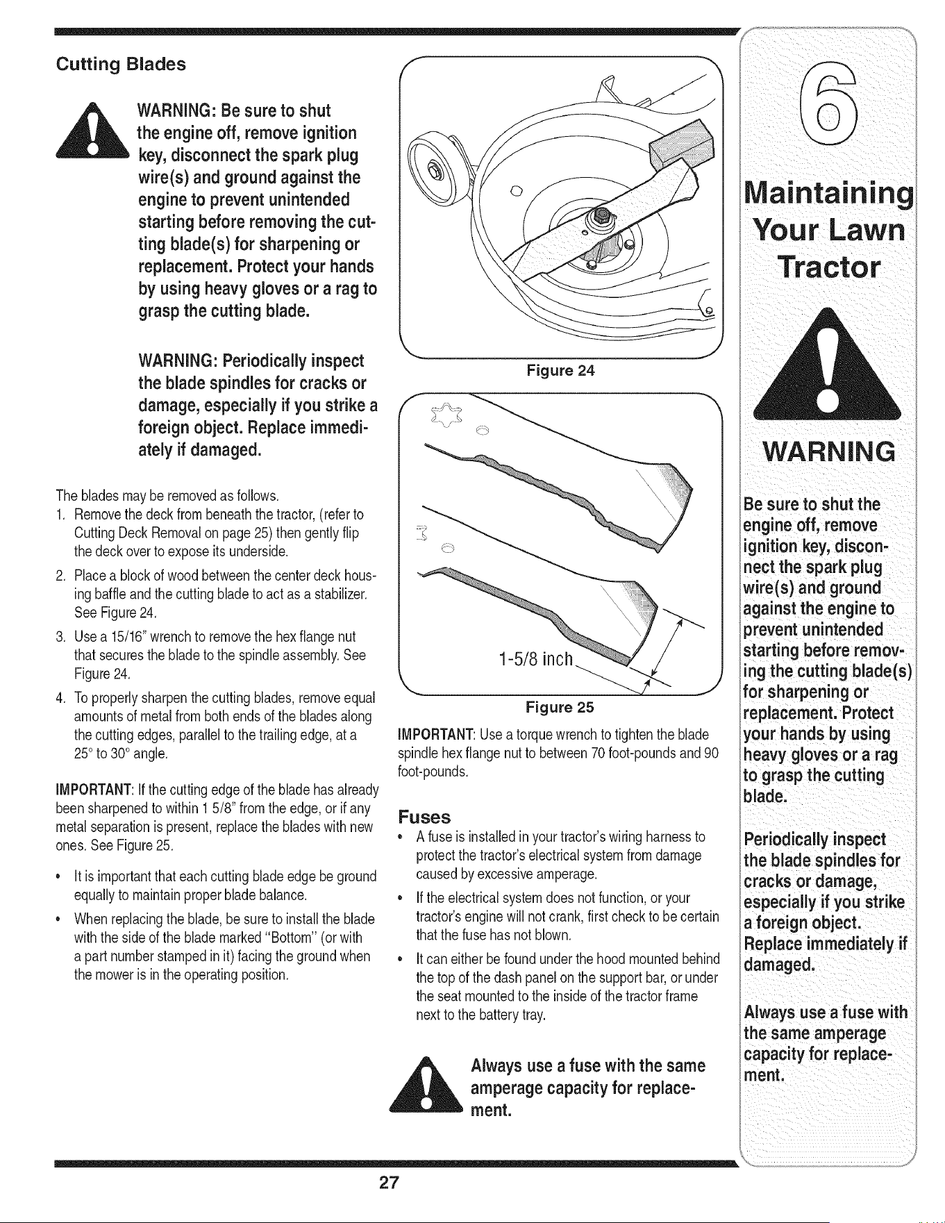
2. Placea blockof wood betweenthe centerdeck hous-
ingbaffleandthe cuttingbladeto act as a stabilizer,
SeeFigure24,
3, Usea 15/16"wrenchto removethe hexflangenut
thatsecuresthe bladeto the spindleassembly.See
Figure24,
4. Toproperlysharpenthe cuttingblades,removeequal
amountsof metalfrombothends of the bladesalong
thecutting edges,parallelto the trailingedge,at a
250to 300angle,
IMPORTANT:Ifthe cuttingedgeof the bladehasalready
beensharpenedto within 1 5/8" fromtheedge,or ifany
metalseparationis present,replacethe bladeswith new
ones,SeeFigure25,
It isimportantthateachcuttingblade edgebeground
equallyto maintainproperbladebalance,
Whenreplacingtheblade,be sureto installthe blade
withthe sideof the blademarked"Bottom" (orwith
a part numberstampedinit) facingthe groundwhen
the mowerisinthe operatingposition.
Figure 24
\\
1-5/8 inch
Figure 25
IMPORTANT:Usea torquewrenchto tightenthe blade
spindlehexflangenut to between70 foot-poundsand90
foot-pounds.
Fuses
• A fuseis installedinyour tractor'swiringharnessto
protectthe tractor'selectricalsystemfromdamage
causedby excessiveamperage.
• Ifthe electricalsystemdoes notfunction,or your
tractor'senginewill notcrank,first checkto becertain
thatthe fusehas notblown.
Itcan eitherbefoundunderthe hoodmountedbehind
the top of the dashpanelon the supportbar,or under
the seatmountedto the insideof the tractorframe
nextto the batterytray.
,__ Always use a fuse with the same
amperage capacity for replace-
ment.
WARNING
Be sure to shut the
engine off, remove
ignition key, discon-
nect the spark plug
wire(s) and ground
against the engine to
prevent unintended
starting before remov-
ing the cutting blade(s
for sharpening or
replacement. Protect
your hands by using
heavy gloves or a rag
to grasp the cutting
blade.
Periodically inspect
the blade spindles for
cracks or damage,
especially if you strike
a foreign object.
:teplace immediately if
damaged.
Always use a fuse with
the same amperage
capacity for replace-
ment.
27
i ioto°i°g
WARNING
Be sure to shutthe
engine off, remove ig-
nition key, disconnect
the spark plug wire(s)
and ground against
the engine to prevent
unintendedstarting
before removingthe
belt(s).
Avoid the possibility of
a pinching injury.Do
not place your fingers
on the idler spring or
between the belt and a
pulleywhile removing
the belt.
,__ WARNING" Be sure to shut
the engine off, remove ignition
• key,disconnect the spark plug
wire(s) and ground against the
engine to prevent unintended
starting before removingthe
belt(s).
All beltson yourtractorare subjectto wearand should
be replacedif anysigns of weararepresent.
iMPORTANT:TheV-beltsfoundon yourtractorare
speciallydesignedto engageand disengagesafely.A
substitute(non-OEM)V-beltcan be dangerousby not
disengagingcompletely.Fora properworkingmachine,
usefactoryapprovedbelts.
,
3.
Tochangeor replacethe deckbelt onyourtractor,
proceedas follows:
1. Removethe beltkeeperrod(s)from aroundthe
enginepulley.
Removethe cuttingdeckas instructedearlierinthis
section.
Removethe beltguardsby removingthe self-tapping
screwsthatfastenthemto the deck.
,
5.
,
7.
8.
Carefullyloosen,butdo not remove,the deck idler
pulleys.
Removethedeck belt fromaroundall pulleys,including
the deckidlerpulleysandthe electricPTOclutch(units
withelectricPTO).
Routethe newbelt as shownin Figure26, 27,and28
andretightenthe deckidlerpulleys.
Reinstallthe beltguardsremovedearlierand remount
the deckto thetractor.
Routethe beltaroundtheenginepulleyand reinstall
the beltkeeperrod(s).
Changing the Lower Deck Belt (46" Decks)
NOTE:Severalcomponentsmustbe removedin orderto
changethe tractor'slowerdeck belt. Seean authorized
MTDServiceDealerto haveyourlowerdrivebelt replaced
or phoneCustomerSupportas instructedon page2 for
informationonorderinga ServiceManual.
Changing the Transmission Drive
Belt
NOTE:Severalcomponentsmustbe removedandspecial
tools(i.e.air/impactwrench)in orderto changethe
tractor'sdrive belt.Seean authorizedMTDServiceDealer
to haveyourdrivebelt replacedor phoneCustomerSup-
portas instructedonpage2 for informationon orderinga
ServiceManual.
28
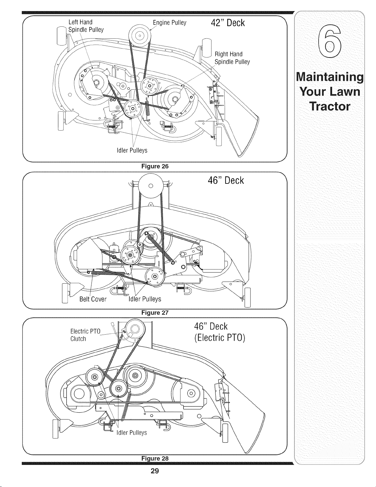
f
Engine Pulley 42" Deck
Left Hand
Spindle Pulley
Right Hand
Spindle Pulley
Idler Pulleys
Figure 26
46" Deck
Belt Cover
Idler Pulleys
Figure 27
46" Deck
Electric PTO
Clutch (Electric PTO)
o 0
idler Pulleys
Figure 28
29
Tractor
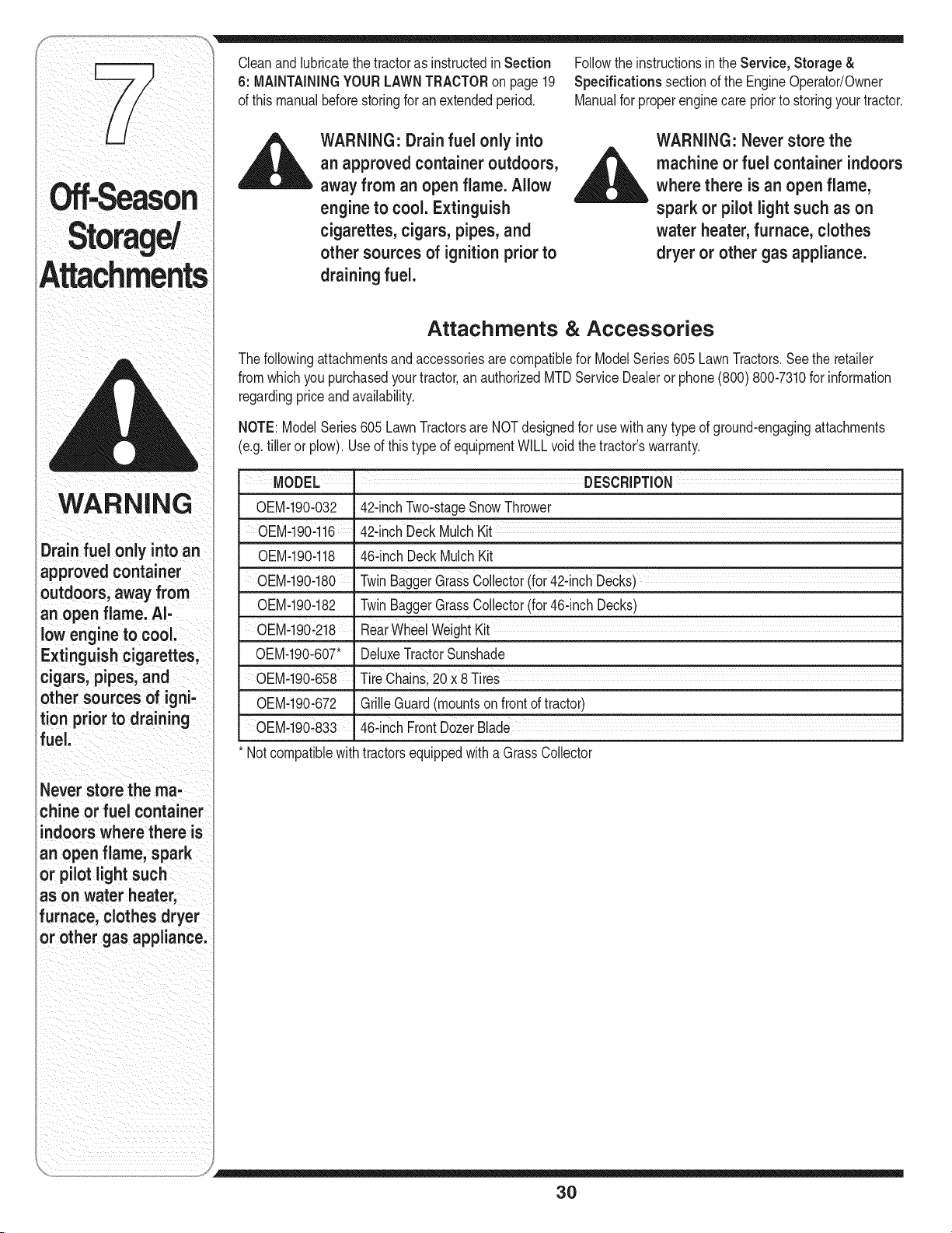
WARNING
Drain fuel only into an
approvedcontainer
outdoors,away from
an open flame. Al-
low engine to cool
Extinguishcigarettes,
cigars, pipes, and
other sources of igni-
tion priorto draining
fuel.
Never store the ma-
chine or fuel container
indoors where there is
an open flame, spark
or pilot lightsuch
as on water heater,
furnace, clothes dryer
or other gas appliance.
Cleanandlubricatethe tractoras instructedin Section
6: MAiNTAiNiNGYOURLAWNTRACTORon page 19
of thismanualbeforestoringfor an extendedperiod.
_ WARNING" Drain fuel only into
an approved containeroutdoors,
away from an open flame. Allow
engine to cool. Extinguish
cigarettes, cigars, pipes, and
other sources of ignition prior to
draining fuel.
Followthe instructionsin the Service, Storage &
Specifications sectionof the EngineOperator/Owner
Manualfor properenginecare priorto storingyourtractor.
WARNING: Never store the
__ achine or fuel container indoors
where there is an open flame,
spark or pilot light such as on
water heater, furnace, clothes
dryer or other gas appliance.
Attachments & Accessories
Thefollowingattachmentsandaccessoriesarecompatiblefor ModelSeries605 LawnTractors.Seethe retailer
fromwhichyou purchasedyourtractor,an authorizedMTDServiceDealeror phone(800) 800-7310for information
regardingpriceandavailability.
NOTE:ModelSeries605 LawnTractorsare NOTdesignedfor usewithany typeof ground-engagingattachments
(e.g.tiller or plow). Useof this type of equipmentWILL voidthe tractor'swarranty.
MODEL I DESCRiPTiON
OEM-190-032 42-inchTwo-stageSnowThrower
OEM-190:1i6 42qnchDeckMulch Kit
OEM-190-118 46-inch DeckMulchKit
_0EM-190480 Twin BaggerGrass Collect0r(for42qnchDeckS)
OEM-190-182 TwinBaggerGrassCollector(for 46-inchDecks)
0EM-190:2i8 RearWheelWeightKit
OEM-190-607" DeluxeTractorSunshade
OEM-190:658
OEM-190-672 GrilleGuard(mountson front of tractor)
OEM.190_833 "46-inch FrontD0zerBlade
* Notcompatiblewithtractorsequippedwitha Grass Collector
30
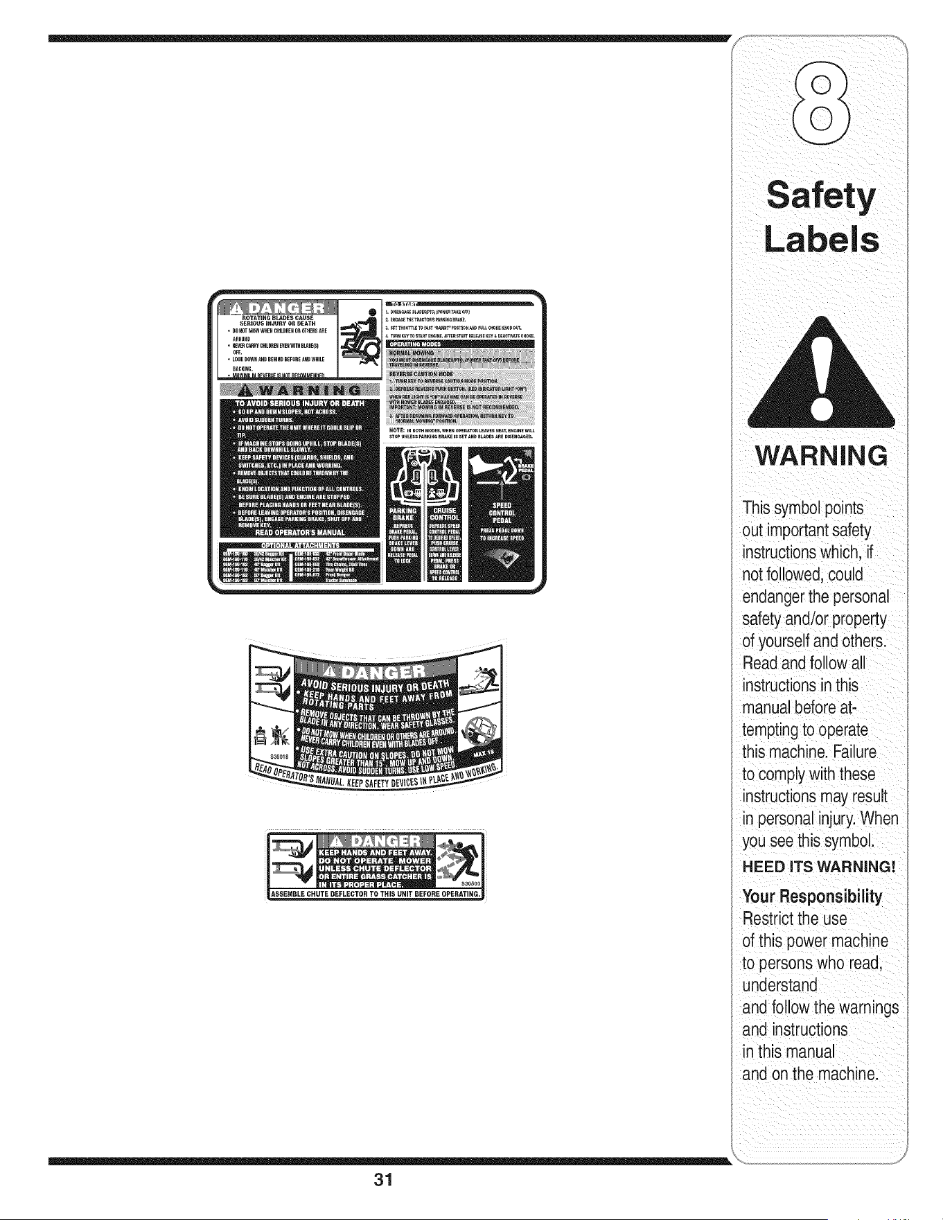
31
WARNING
This symbol points
out importantsafety
instructionswhich, if
not followed,could
endangerthe personal
safety and/or property
of yourselfand others.
Readand follow all
instructionsinthis
manual beforeat-
temptingto operate
this machine. Failure
to comply with these
instructionsmay result
in personalinjury.When
you see this symbol.
HEED ITS WARNING!
Your Responsibility
Restrictthe use
of this power machine
to persons who read,
understand
and follow the warnings
and instructions
in this manual
and on the machine.
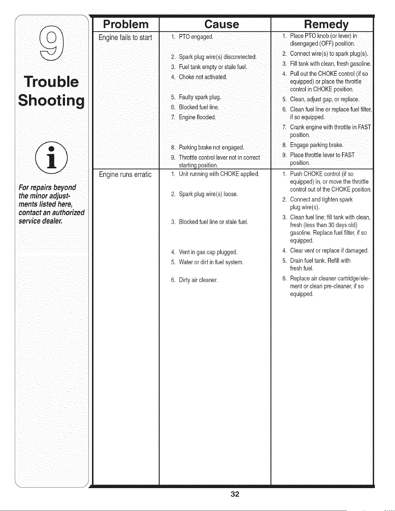
Trou
Shootin
e
For repairs beyond
the minor adjust-
ments listed here,
contact an authorized
service dealer.
Pro bl e m Ca use Remedy
Enginefails to start I 1 PTOengaged. 1 PlacePTOknob(orlever)in
I disengaged(OFF)position.
I 2. Sparkplugw re(s)disconnected. 2. Connectwire(s)to sparkplug(s).
3 Fueltankem t or stalefuel 3 F tankwth c ean freshgaso ne
py . •
I 4 Chokenot actvated 4. Pullout the CHOKEcontrol(if so
I " ' equipped)orplacethe throttle
I controlinCHOKEposition.
I 5. Faultysparkplug, 5. Clean,adjustgap,or replace
I 6. Blockedfuel line. 6. Cleanfuel lineor replacefuelfilter,
I 7. Engineflooded, if so equipped.
I I 7 Crank enginewith thrott e n FAST
I position.
I 8 Parkngbrakenotengaged I 8. Engageparkingbrake.
I 9. Throttlecontro levernotin correct , 9. Placethrottleleverto FAST
I startingposition. _ position.
Engineruns erratic 1, UnitrunningwithCHOKEapplied, 1, PushCHOKEcontrol(if so
2, Sparkplugwire(s)loose,
3, Blockedfuellineor stale fuel,
4, Ventingas cap plugged,
5, Waterordirt infuel system,
6. Dirty aircleaner.
32
equipped)in,or movethe throttle
controlout of the CHOKEposition.
2. Connectandtightenspark
plugwire(s).
3. Cleanfuel line;fill tankwith clean,
fresh(lessthan30 daysold)
gasoline.Replacefuel filter,ifso
equipped.
4. Clearventor replaceif damaged.
5. Drainfuel tank. Refillwith
freshfuel.
6. Replaceaircleanercartridge/ele-
mentor cleanpre-cleaner,if so
equipped.
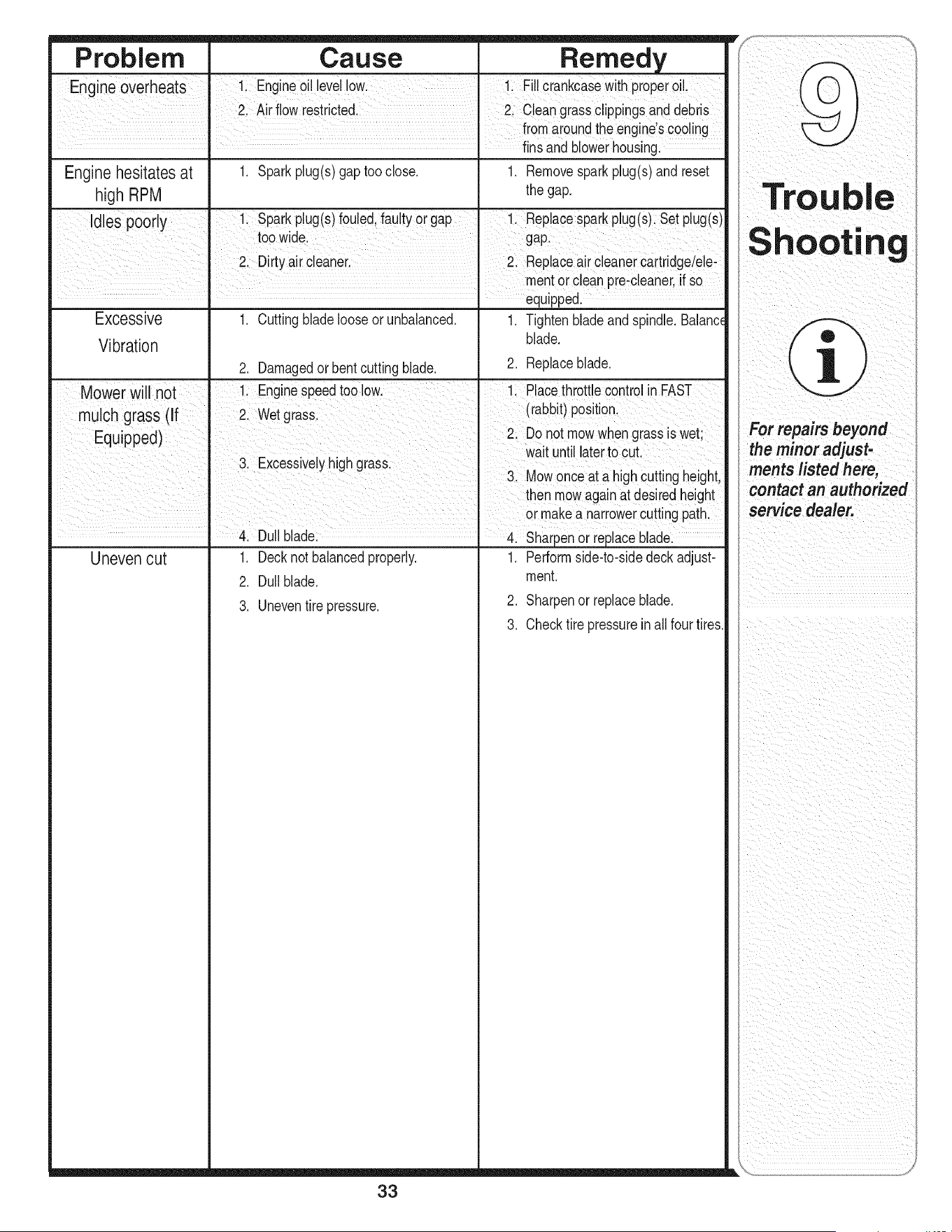
Problem Cause Remedy
Engineoverheats !i Engine oi! levellow. !i Fi!!Ciankcasewith pr0pero!!,
21Air flow restricted. 2 c eangrassclippingsand debiis
fromaroundthe engines €00!ing
..... finsandblowerhousing.
Enginehesitates at 1. Sparkplug(s)gap tooclose, 1, Removesparkplug(s)and reset
high RPM the gap,
idles poorl 1 Sparkpug(s)foued fautyorgap 1 Repacesparkpug(s)Setpug(s)
y ' ' t
to0 wide_ gap:
2 Dirtyair €eaner Replaceair cleanercartrdgdele:
mentor cleanpre:cleaner if So
equipped.
Excessive 1. Cuttingbladelooseor unbalanced. 1. Tightenbladeandspindle. Balanc_
Vibration blade.
2. Damagedorbentcuttingblade. 2. Replaceblade.
Mower will not 11 Enginespeedtoo iowl 1; P!acethrott!e€ontrolin FAST
ohgrass (If wet grass (rabbit)p0siti°n.
Equipped) 2. D0not m0wwhengrass s wet
wat unt aterto cut
3. Excessivelyhighgrassl ,,,
_. Mowonce a! a nigncuttingneight,
then mowagainat desiredheight
or makea narrowerCuttingpath,
Duiiblade &sharpen or repiacebiade:
Uneven cut 1. Decknotbalancedproperly. 1. Performside-to-sidedeck adjust-
2. Dullblade, ment.
2. Sharpenor replaceblade.
3. Uneventire pressure.
3. Checktire pressureinall fourtires.
33
rou
iiii_i_!iii_iiI _i_ii _iii_ii_!i_
the minor adjust-
contact
_iiii_i_i_i_iii__ _i_ !ii
_ii!_I_iiiii_i_i_i_ii_ii_i_i/i _ _i_i__
i i i _i ii iiili_ i_ii_iii i _ _i_
iiiii _ i i i _i
i i i _ _ ii_i iiiiii i
iiii ii i
ii_ i _ ii i iii i i iiiii I
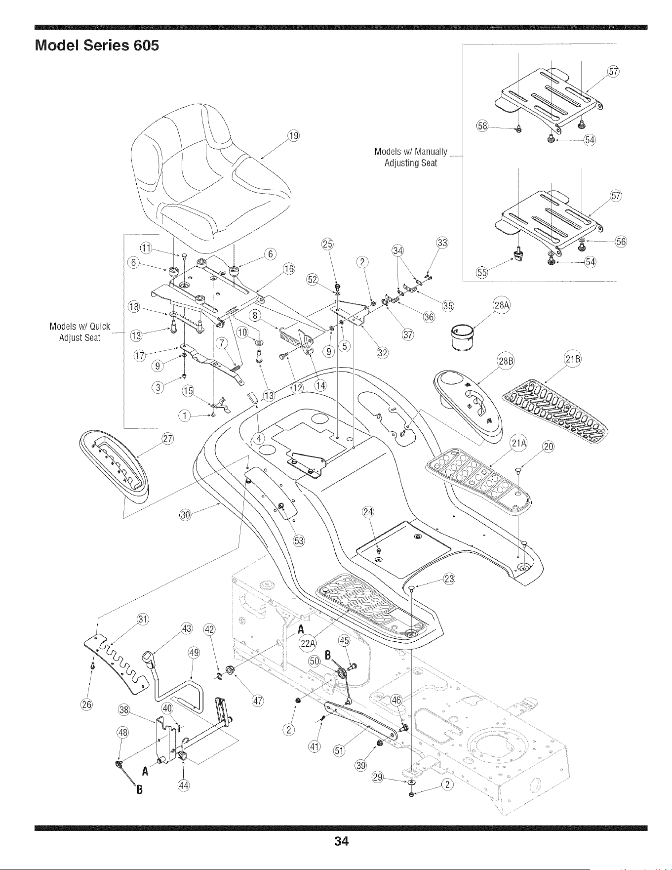
Model Series 605
Modelsw/Quick
AdjustSeat
Modelsw/Manually .............
Adjusting Seat
@
34
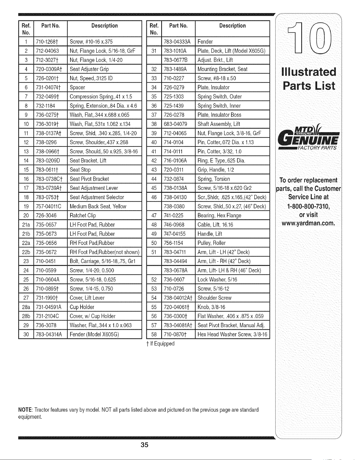
Ref. Part No. Description Ref. PartNo. Description
No. No.
1 710-1268t Screw,#10-16x.375 783-04333A Fender
2 712-04063 Nut, FlangeLock,5/16-18,GrF
3 712-3027t Nut, FlangeLock, 1/4-20
4 720-0309At SeatAdjusterGrip
5 726-0201t Nut, Speed,.3125ID
6 731-04074t Spacer
7 732-0499t CompressionSpring,.41x 1.5
8 732-1184 Spring,Extension,.84Dia.x 4.6
9 736-0275t Wash,Flat,.344x.688x.065
10 736-3019t Wash,Flat,.531x1.062x.134
11 738-0137At Screw,Shld, .340x.285,1/4-20
12 738-0296 Screw,Shoulder,.437x.268
13 738-0966t Screw,Should,.50x.925,3/8-16
14 783-0209D Seat Bracket,Lift
15 783-0611t SeatStop
16 783-07380t Seat PivotBracket
17 783-0739At SeatAdjustmentLever
18 783-0753t SeatAdjustmentSelector
19 757-040110 MediumBackSeat,Yellow
20 726-3046 RatchetClip
21a 735-0657 LH Foot Pad,Rubber
21b 735-0673 LH Foot Pad,Rubber
22a 735-0656 RH FootPad,Rubber
22b 735-0672 RH FootPad,Rubber(notshown)
23 710-0451 Bolt, Carriage,5/16-18,.75,Grl
24 710-0599 Screw,1/4-20,0.500
25 710-0604A Screw,5/16-18,0.625
26 710-0895t Screw,1/4-15,0.750
27 731-1990t Cover,Lift Lever
28a 731-04591A Cup Holder
28b 731-21040 Cover,w/Cup Holder
29 736-3078 Washer,Fht,.344 x 1.0x.063
30 783-04314A Fender(ModeIX605G)
31 783-1010A Plate,Deck, Lift(ModeIX605G)
783-0677B Adjust.Brkt., Lift
32 783-1489A MountingBracket,Seat
33 710-0227 Screw,#8-18x.50
34 726-0279 Plate,Insulator
35 725-1303 SpringSwitch,Outer
36 725-1439 SpringSwitch,inner
37 726-0278 Plate,InsulatorBoss
38 683-04079 ShaftAssembly,Lift
39 712-04065 Nut,FlangeLock,3/8-16,GrF
40 714-0104 Pin,Cotter,.072Dia.x 1.13
41 714-0111 Pin,Cotter,3/32, 1.0
42 716-0106A Ring,E Type,.625Dia.
43 720-0311 Grip,Handle,1/2
44 732-0874 Spring,Torsion
45 738-0138A Screw,5/16-18x.620Gr2
46 738-04130 Scr.,Shldr,.625x.165,(42"Deck)
738-0380 Screw,Shld,.50x.27,(46"Deck)
47 741-0225 Bearing,Hex Flange
48 746-0968 Cable,Lift, 16.16
49 747-04155 Handle,Lift
50 756-1154 Pulley,Roller
51 783-04711 Arm, Lift- LH (42"Deck)
783-04494 Arm, Lift- RH(42"Deck)
783-0678A Arm, Lift- LH& RH (46" Deck)
52 736-0607 LockWasher,5/16
53 710-0726 Screw,5/16-12
ShoulderScrew
Knob,3/8-16
FiatWasher,.406x .875x .059
SeatPivotBracket,ManualAdj.
HexHeadWasherScrew,3/8-16
54 738-04012At
55 720-04061t
56 736-0300t
57 783-04081At
58 710-0870t
fir Equipped
NOTE:Tractorfeaturesvary by model.NOTall partslistedaboveandpicturedonthe previouspagearestandard
equipment.
Illustrated
! PARTS
To order replacement
parts, call the Customer
Service Line at
1-800-800-7310,
or visit
www.yardman.com.
35
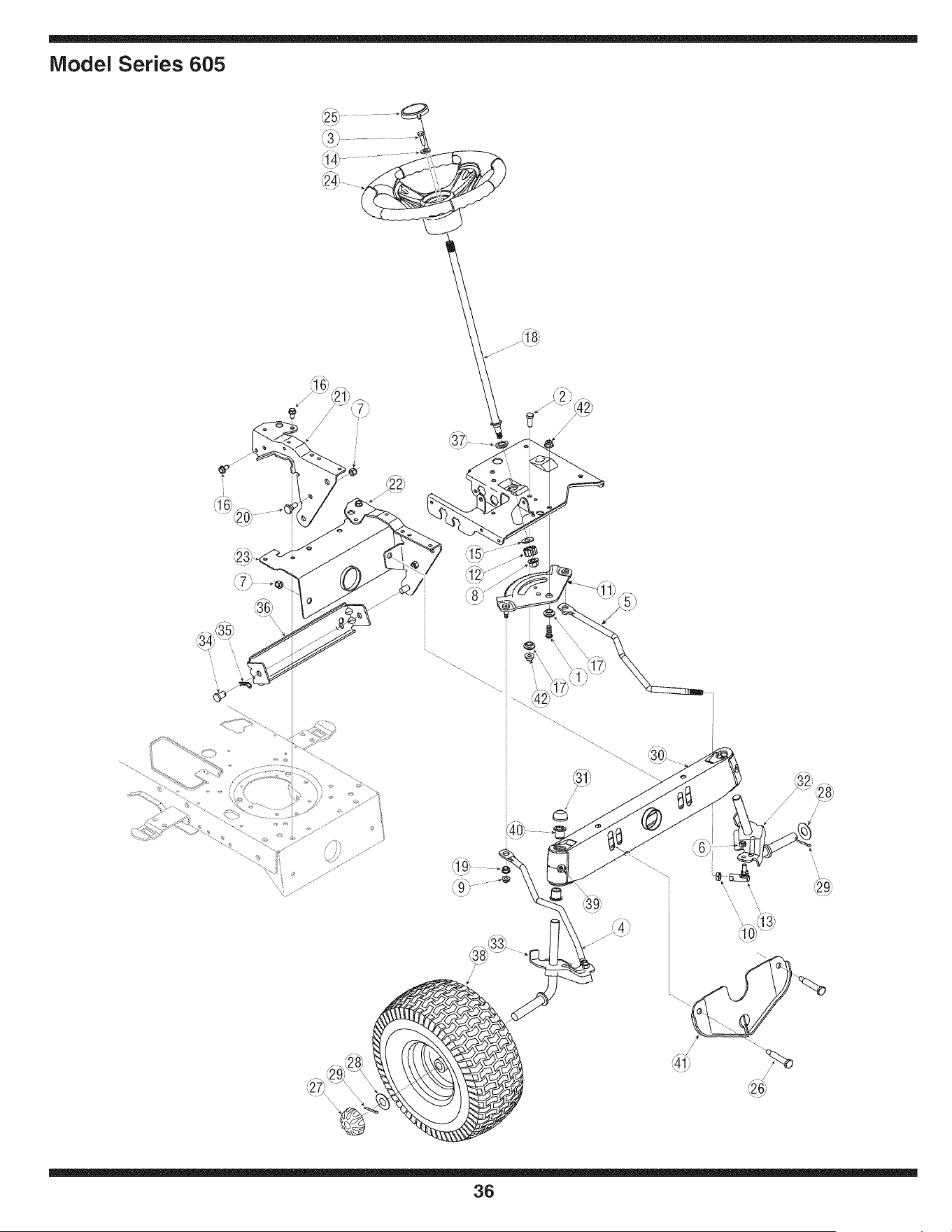
iVlodel Series 605
\
36
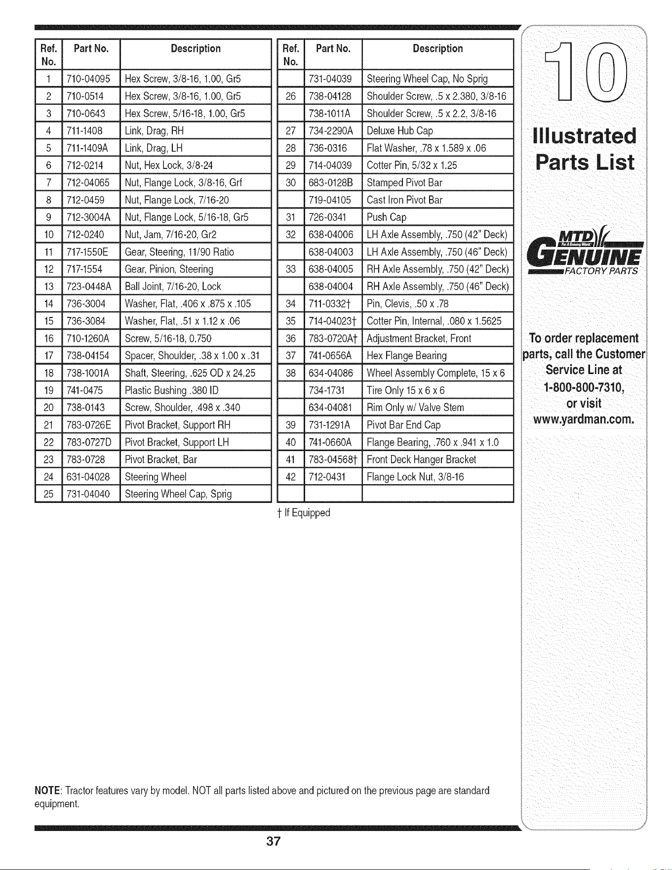
Fief. Part No. Description
No,
1 710-04095 HexScrew,3/8-16, 1.00,Gr5
2 710-0514 HexScrew,3/8-16,1.00,Gr5
3 710-0643 HexScrew,5/16-18,1.00,Gr5
4 711-1408 Link,Drag, RH
5 711-1409A Link,Drag,LH
6 712-0214 Nut,Hex Lock,3/8-24
7 712-04065 Nut,FlangeLock,3/8-16, Grf
8 712-0459 Nut,FlangeLock,7/16-20
9 712-3004A Nut,FlangeLock,5/16-18,Gr5
10 712-0240 Nut,Jam,7/16-20,Gr2
11 717-1550E Gear,Steering,11/90Ratio
12 717-1554 Gear,Pinion,Steering
13 723-0448A BallJoint, 7/16-20,Lock
14 736-3004 Washer,Fiat,.406x .875x .105
15 736-3084 Washer,Fiat,.51x 1.12x .06
16 710-1260A Screw,5/16-18,0.750
17 738-04154 Spacer,Shoulder,.38 x 1.00x .31
18 738-1001A Shaft,Steering,.625ODx 24.25
19 741-0475 PlasticBushing.3801D
20 738-0143 Screw,Shoulder,.498x.340
21 783-0726E PivotBracket,SupportRH
22 783-0727D PivotBracket,SupportLH
23 783-0728 PivotBracket,Bar
24 631-04028 SteeringWheel
25 731-04040 SteeringWheelCap,Sprig
Fief. PartNo. Description
No,
731-04039 SteeringWheelCap,No Sprig
26 738-04128 ShoulderScrew,.5x 2.380,3/8-16
738-1011A ShoulderScrew,.5x 2.2,3/8-16
27 734-2290A DeluxeHubCap
28 736-0316 Fiat Washer,.78x 1.589x .06
29 714-04039 CotterPin,5/32 x 1.25
30 683-0128B StampedPivotBar
719-04105 Cast ironPivotBar
726-0341 PushCap
31
32
LH AxleAssembly,.750(42" Deck)
LH AxleAssembly,.750(46" Deck)
RHAxleAssembly,.750(42"Deck)
RHAxleAssembly,.750(46"Deck)
Pin,Clevis,.50x .78
CotterPin,internal,.080x 1.5625
AdjustmentBracket,Front
638-04006
638-04003
33 638-04005
638-04004
34 711-0332t
35 714-04023t
36 783-0720At
37 _ 741-0656A _ Hex FlangeBearing
38 634-04086 WheelAssemblyComplete,15x6
734-1731 TireOnly 15x 6 x 6
634-04081 RimOnlyw/Valve Stern
39 731-1291A PivotBarEnd Cap
40 741-0660A FlangeBearing,.760x .941x 1.0
41 783-04568t FrontDeck HangerBracket
42 712-0431 FlangeLockNut,3/8-16
t If Equipped
NOTE:Tractorfeaturesvary by model.NOTall partslistedaboveandpicturedonthe previouspagearestandard
equipment.
37
To orderreplacement
parts, call the Customer
Service Line at
1'800=800'73101
or visit
w :yardman:coml
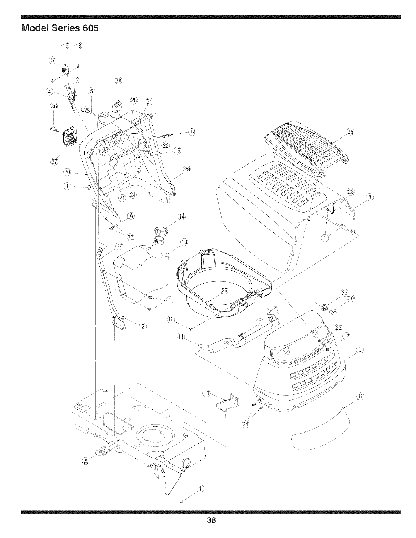
Model Series 605
i
\
\\\\\\\\\\\\\\\
i!
\
x
38
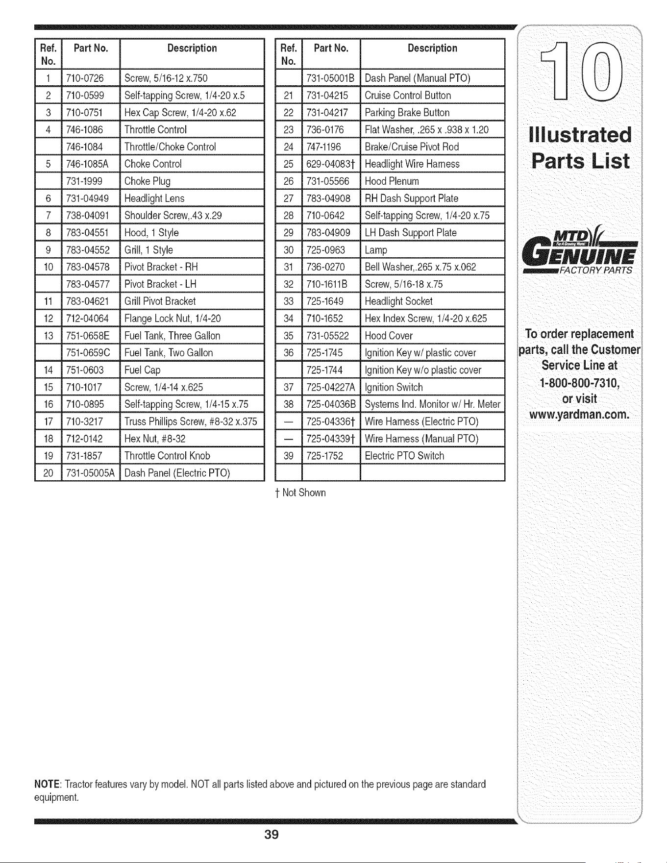
Fief. PartNo. Description
No.
1 710-0726 Screw,5/16-12x.750
2 710-0599 Self-tappingScrew,1/4-20x.5
3 710-0751 Hex CapScrew,1/4-20x.62
4 746-1086 ThrottleControl
746-1084 Throttle/ChokeControl
5 746-1085A ChokeControl
731-1999 ChokePlug
6 731-04949 HeadlightLens
7 738-04091 ShoulderScrew,.43x.29
8 783-04551 Hood, 1 Style
9 783-04552 Grill, 1 Style
10 783-04578 PivotBracket- RH
783-04577 PivotBracket- LH
11 783-04621 GrillPivotBracket
12 712-04064 FlangeLockNut,1/4-20
13 751-0658E FuelTank,ThreeGallon
751-0659C FuelTank,TwoGallon
14 751-0603 FuelCap
15 710-1017 Screw,1/4-14x.625
16 710-0895 Self-tappingScrew,1/4-15x.75
17 710-3217 TrussPhillipsScrew,#8-32x.375
18 712-0142 Hex Nut,#8-32
19 731-1857 ThrottleControl Knob
20 731-05005A Dash Panel(ElectricPTO)
Fief. PartNo. Description
No.
731-05001B DashPanel(ManualPTO)
21 731-04215 CruiseControlButton
22 731-04217 ParkingBrakeButton
23 736-0176 FiatWasher,.265x .938x 1.20
24 747-1196 Brake/CruisePivot Rod
25 629-040831- HeadlightWireHarness
26 731-05566 HoodPlenum
27 783-04908 RHDashSupportPlate
28 710-0642 Self-tappingScrew,1/4-20x.75
29 783-04909 LH DashSupportPlate
30 725-0963 Lamp
31 736-0270 BellWasher,.265x.75x.062
32 710-1611B Screw,5/16-18x.75
33 725-1649 HeadlightSocket
34 710-1652 Hex indexScrew,1/4-20x.625
35 731-05522 HoodCover
36 725-1745 IgnitionKeyw/ plasticcover
725-1744 IgnitionKeyw/o plasticcover
37 725-04227A IgnitionSwitch
38 725-04036B SystemsInd. Monitorw/ Hr.Meter
-- 725-043361- Wire Harness(ElectricPTO)
-- 725-043391- Wire Harness(ManualPTO)
39 725-1752 ElectricPTOSwitch
1-NotShown
NOTE:Tractorfeaturesvary by model.NOTall partslistedaboveandpicturedonthe previouspagearestandard
equipment.
i__ _ii_ ii_iii:_i_i_!_ii_!i_iii_ii__i_!_iii_i_
Parts List
_mm_mFACTORY PARTS
To order replacement
parts, call the Customer
Service Line at
1-800-800o7310,
or visit
www.yardman.com.
39
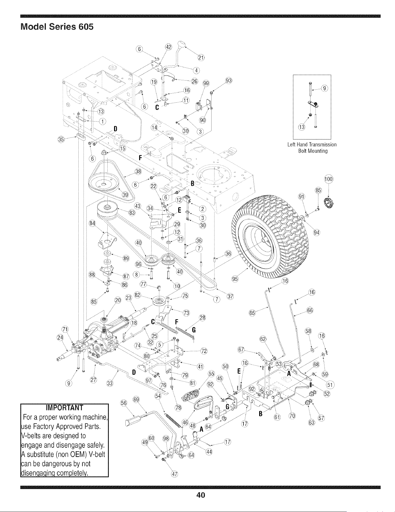
Model Series 605
, ,
, , f,, 4\
, ,
, ,
E
, ,
, ,
C
Left HandTransmission
Bolt Mounting
E
E
/y-_ \
'\
iMPORTANT
Fora proper working machine
use FactoryApproved Parts.
V-belts are designed to
engage and disengage safely.
A substitute (non OEM) V-belt
can be dangerous by not
disen a in com letel.
/
f_
d_
Ei
/
\\\\
\
4O
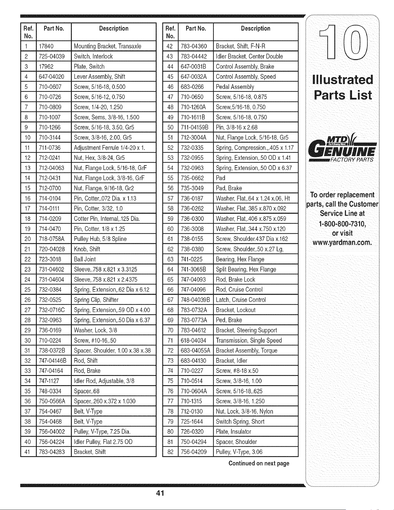
Fief. PartNo. Description
No.
1 17840 MountingBracket,Transaxle
2 725-04039 Switch,Interlock
3 17962 Plate,Switch
4 647-04020 LeverAssembly,Shift
5 710-0607 Screw,5/16-18,0.500
6 710-0726 Screw,5/16-12,0.750
7 710-0809 Screw,1/4-20,1.250
8 710-1007 Screw,Seres,3/8-16,1.500
9 710-1266 Screw,5/16-18,3.50,Gr5
10 710-3144 Screw,3/8-16,2.00,Gr5
11 711-0736 AdjustmentFerrule1/4-20x 1.
12 712-0241 Nut,Hex,3/8-24,Gr5
13 712-04063 Nut,FlangeLock,5/16-18,GrF
14 712-0431 Nut,FlangeLock,3/8-16,GrF
15 712-0700 Nut,Flange,9/16-18,Gr2
16 714-0104 Pin,Cotter,.072Dia.x 1.13
17 714-0111 Pin,Cotter,3/32, 1.0
18 714-0209 CotterPin,Internal,.125Dia.
19 714-0470 Pin,Cotter,1/8 x 1.25
20 718-0758A PulleyHub,5/8Spline
21 720-04028 Knob,Shift
22 723-3018 BallJoint
23 731-04602 Sleeve,.758x.821x 3.3125
24 731-04604 Sleeve,.758x.821x 2.4375
25 732-0384 Spring,Extension,.62Diax6.12
26 732-0525 SpringClip,Shifter
27 732-0716C Spring,Extension,.590Dx4.00
28 732-0963 Spring,Extension,.50Diax6.37
29 736-0169 Washer,Lock,3/8
30 710-0224 Screw,#10-16,.50
31 738-0372B Spacer,Shoulder,1.00x.38 x.38
32 747-04146B Rod,Shift
33 747-04164 Rod, Brake
34 747-1127 IdlerRod,Adjustable,3/8
35 748-0334 Spacer,.68
36 750-0566A Spacer,.260x.372x 1.030
37 754-0467 Belt,V-Type
38 754-0468 Belt,V-Type
39 756-04002 Pulley,V-Type,7.25Dia.
40 756-04224 IdlerPulley,Flat2.75OD
41 783-04283 Bracket,Shift
Fief. Part No. Description
No.
42 783-04360 Bracket,Shift, F-N-R
43 783-04442 IdlerBracket,CenterDouble
44 647-0031B ControlAssembly,Brake
45 647-0032A ControlAssembly,Speed
46 683-0266 PedalAssembly
47 710-0650 Screw,5/16-18,0.875
48 710-1260A Screw,5/16-18,0.750
49 710-1611B Screw,5/16-18,0.750
50 711-04159B Pin,3/8-16x2.68
51 712-3004A Nut,FlangeLock,5/16-18,Gr5
52 732-0335 Spring,Compression.,.405x 1.17
53 732-0955 Spring,Extension,.50OD x 1.41
54 732-0963 Spring,Extension,.50OD x 6.37
55 735-0662 Pad
56 735-3049 Pad,Brake
57 736-0187 Washer,Flat,.64x 1.24x.06, Ht
58 736-0262 Washer,Flat,.385x.870x.092
59 736-0300 Washer,Flat,.406x.875x.059
60 736-3008 Washer,Flat,.344x.750x.120
61 738-0155 Screw,Shoulder.437Diax.162
62 738-0380 Screw,Shoulder,.50x.27Lg,
63 741-0225 Bearing,HexFlange
64 741-3065B Split Bearing,HexFlange
65 747-04093 Rod,BrakeLock
66 747-04096 Rod,CruiseControl
67 748-04039B Latch,CruiseControl
68 783-0732A Bracket,Lockout
69 783-0773A Ped,Brake
70 783-04612 Bracket,SteeringSupport
71 618-04034 Transmission,SingleSpeed
72 683-04055A BracketAssembly,Torque
73 683-04130 Bracket,Idler
74 710-0227 Screw,#8-18x.50
75 710-0514 Screw,3/8-16, 1.00
76 710-0604A Screw,5/16-18,.625
77 710-1315 Screw,3/8-16, 1.250
78 712-0130
79 725-1644
80 726-0320
81 750-04294
82 756-04209
Nut,Lock,3/8-16,Nylon
SwitchSpring,Short
Plate,Insulator
Spacer,Shoulder
Pulley,V-Type,3.06
Continued on nextpage
41
Parts List
_FACTORY PARTS
i ¸¸i i i i
Too,derrop aoo.,oot
parts,°,,,
Service Line at
or visit
www,yardman,com,
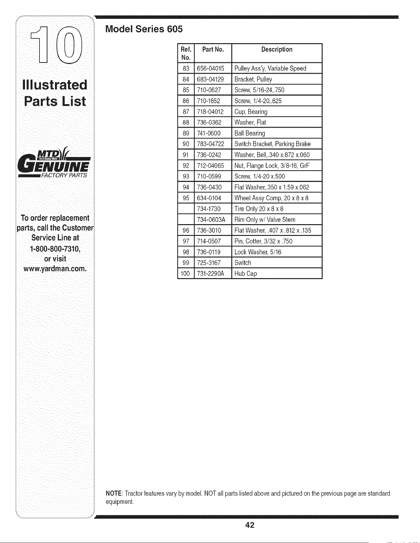
i Toorderreplacement
parts, call the Customer
Service Line at
1=800-800-7310,
or visit
www.yardman.corn.
iVlodel Series 605
Ref. Part No. Description
No.
-- =
83 656-04015 PulleyAss'y,VariaNeSpeed
84 683-04129 Bracket,Pulley
85 710-0627 Screw,5/16-24,.750
L
86 710-1652 Screw,1/4-20,.625
87 718-04012 Cup,Bearing
88 736-0362 Washer,Fiat
89 741-0600 BallBearing
• 90 _ 783-04722 SwitchBracket,ParkingBrake
91 736-0242 Washer,Bell,.340x.872x.060
92 712-04065 Nut,FlangeLock,3/8-16, GrF
93 710-0599 Screw,1/4-20x.500
94 736-0430 FlatWasher,.350x1.59x.062
95 634-0104 WheelAssyCornp,20 x 8 x 8
734-1730 Tire Only20 x 8 x 8
734-0603A RimOnlyw/Valve Stern
96 736-3010 FiatWasher,.407x .812x .135
97 714-0507 Pin,Cotter,3/32 x.750
98 736-0119 LockWasher,5/16
99 725-3167 Switch
100 731-2290A HubCap
NOTE:Tractorfeaturesvary bymodel.NOTall partslisted aboveand picturedon the previouspagearestandard
equipment.
42
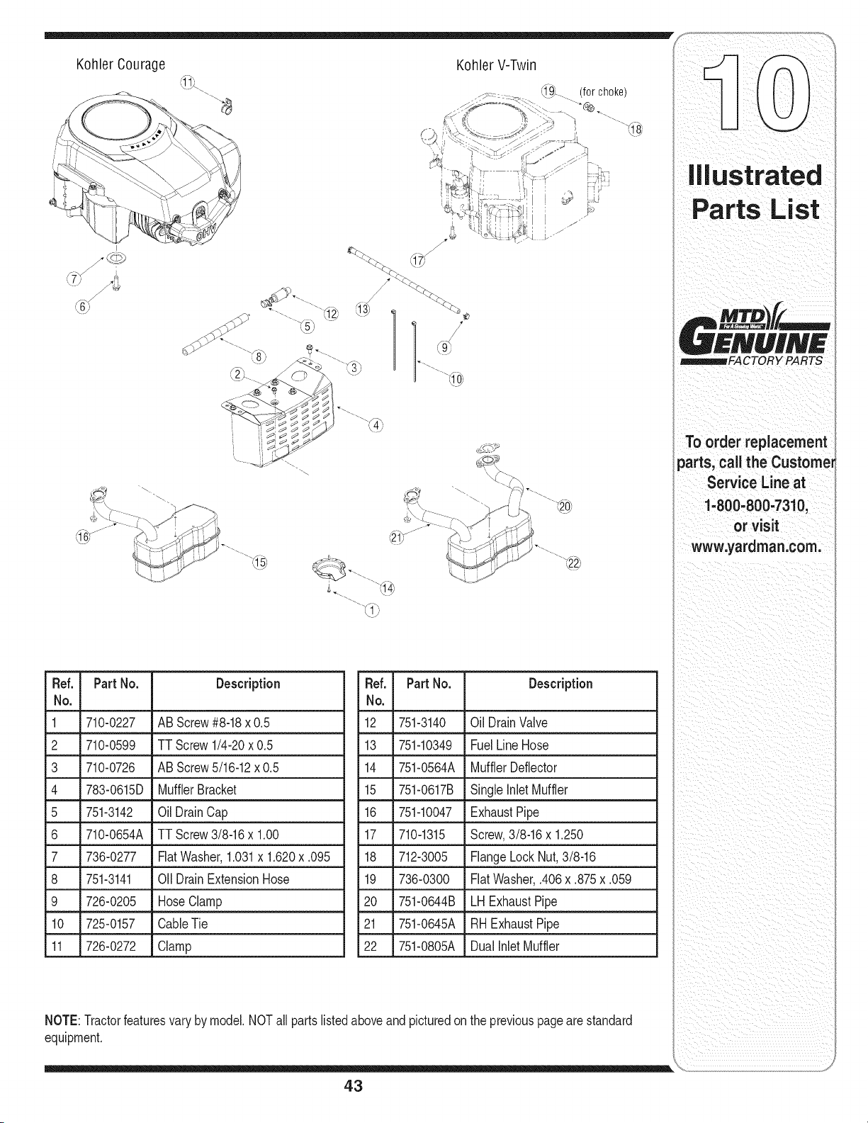
Kohler Courage Kohler V-Twin
'_. (for choke)
I
Ref. PartNo. Description
No,
1 710-0227 AB Screw#8-18x 0.5
2 710-0599 TT Screw1/4-20x 0.5
3 710-0726 AB Screw5/16-12x 0.5
4 783-0615D MufflerBracket
5 751-3142 Oil DrainCap
6 710-0654A TT Screw3/8-16x 1.00
7 736-0277 Fiat Washer,1.031x 1.620x .095
8 751-3141 Oil DrainExtensionHose
9 726-0205 Hose Clamp
10 725-0157 CableTie
11 726-0272 Clamp
Ref. PartNo. Description
No,
12 751-3140 Oil DrainValve
13 751-10349 FuelLineHose
14 751-0564A MufflerDeflector
15 751-0617B Single inlet Muffler
16 751-10047 ExhaustPipe
17 710-1315 Screw,3/8-16x 1.250
18 712-3005 FlangeLockNut,3/8-16
19 736-0300 FiatWasher,.406x .875x .059
20 751-0644B LH ExhaustPipe
21 751-0645A RH ExhaustPipe
22 751-0805A Dualinlet Muffler
NOTE:Tractorfeaturesvary by model.NOTall partslistedaboveandpicturedonthe previouspagearestandard
equipment.
43
'Y PARTS
To order replacement
parts, call the Custome_
Service Line at
1-800-800-7310,
or visit
www.yardman.com.
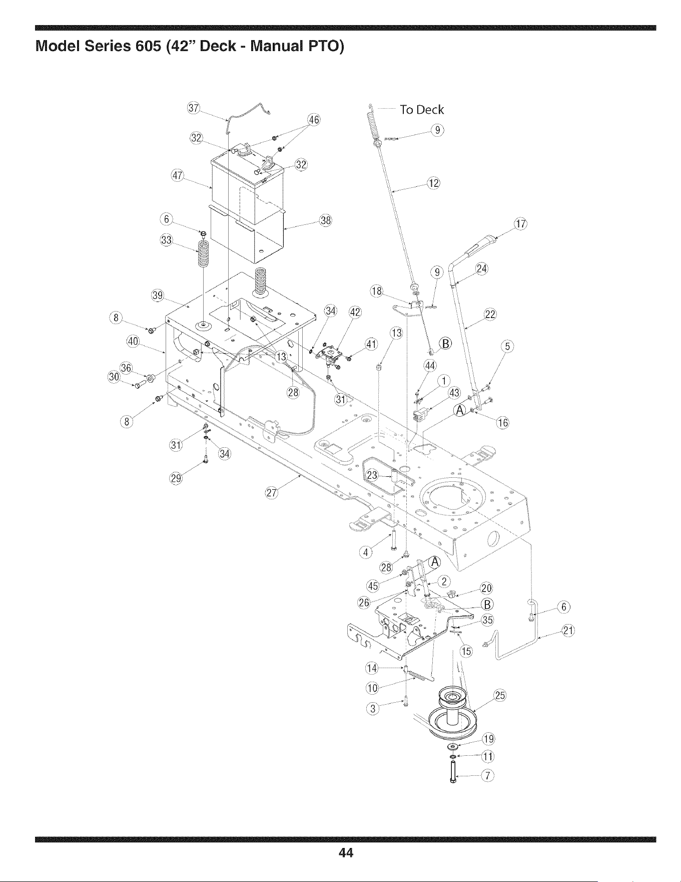
Model Series 605 (42" Deck - Manual PTO)
\\
\\
./
/'
/
44
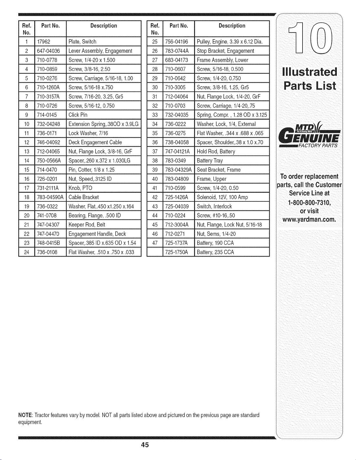
Fief. PartNo. Description
No.
1 17962 Plate,Switch
2 647-04036 LeverAssembly,Engagement
3 710-0778 Screw,1/4-20x 1.500
4 710-0859 Screw,3/8-16,2.50
5 710-0276 Screw,Carriage,5/16-18,1.00
6 710-1260A Screw,5/16-18x.750
7 710-3157A Screw,7/16-20,3.25, Gr5
8 710-0726 Screw,5/16-12,0.750
9 714-0145 ClickPin
10 732-04248 ExtensionSpring,.380Dx 3.9LG
11 736-0171 LockWasher,7/16
12 746-04092 DeckEngagementCable
13 712-04065 Nut, FlangeLock,3/8-16,GrF
14 750-0566A Spacer,.260x.372x 1.030LG
15 714-0470 Pin,Cotter,1/8 x 1.25
16 726-0201 Nut,Speed,.3125ID
17 731-2111A Knob,PTO
18 783-04590A CableBracket
19 736-0322 Washer,Flat,.450xl.250 x.164
20 741-0708 Bearing,Flange,.5001D
21 747-04307 KeeperRod, Belt
22 747-04470 EngagementHandle,Deck
23 748-0415B Spacer,.385IDx.635OD x 1.54
24 736-0108 FiatWasher,.510x .750x .033
Fief. PartNo. Description
No.
25 756-04196 Pulley,Engine,3.39x 6.12Dia.
26 783-0744A Stop Bracket,Engagement
27 683-04173 FrameAssembly,Lower
28 710-0607 Screw,5/16-18,0.500
29 710-0642 Screw,1/4-20,0.750
30 710-3005 Screw,3/8-16,1.25,Gr5
31 712-04064 Nut,FlangeLock,1/4-20,GrF
32 710-0703 Screw,Carriage,1/4-20,.75
33 732-04035 Spring,Compr., 1.28OD x 3.125
34 736-0222 Washer,Lock,1/4,External
35 736-0275 FlatWasher,.344x .688x .065
36 738-04058 Spacer,Shoulder,.38x1.0x.70
37 747-04121A HoldRod,Battery
38 783-0349 BatteryTray
39 783-04329A Seat Bracket,Frame
40 783-04809 Frame,Upper
41 710-0599 Screw,1/4-20,0.50
42 725-1426A Solenoid,12V,100Amp
43 725-04039 Switch,Interlock
44 710-0224 Screw,#10-16,.50
45 712-3004A Nut,Flange,Lock Nut,5/16-18
46 712-0271 Nut,Seres,1/4-20
47 725-1737A Battery,190CCA
725-1750A Battery,235CCA
NOTE:Tractorfeaturesvary by model.NOTall partslistedaboveandpicturedonthe previouspagearestandard
equipment.
To order replacement
parts, call the Customer
Service Line at
1.800..800=7310,
or visit
www,yardman:com:
45
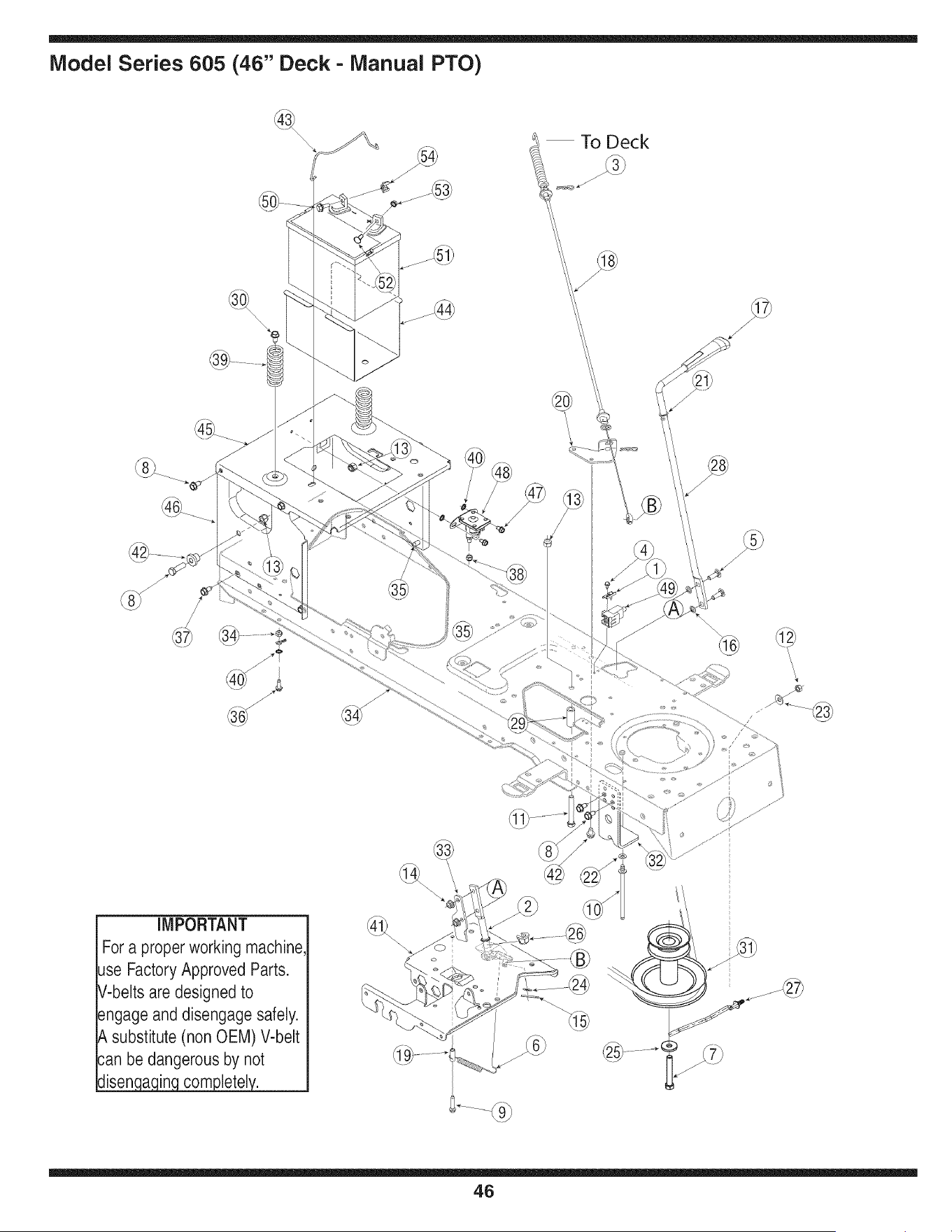
Model Series 605 (46" Deck - Manual PTO)
To Deck
J
IMPORTANT
Fora proper working machine,
use FactoryApproved Parts.
V-belts are designed to
engage and disengage safely.
A substitute (non OEM) V-belt
can be dangerous by not
disen ain com letel.
@
®
\
\
46
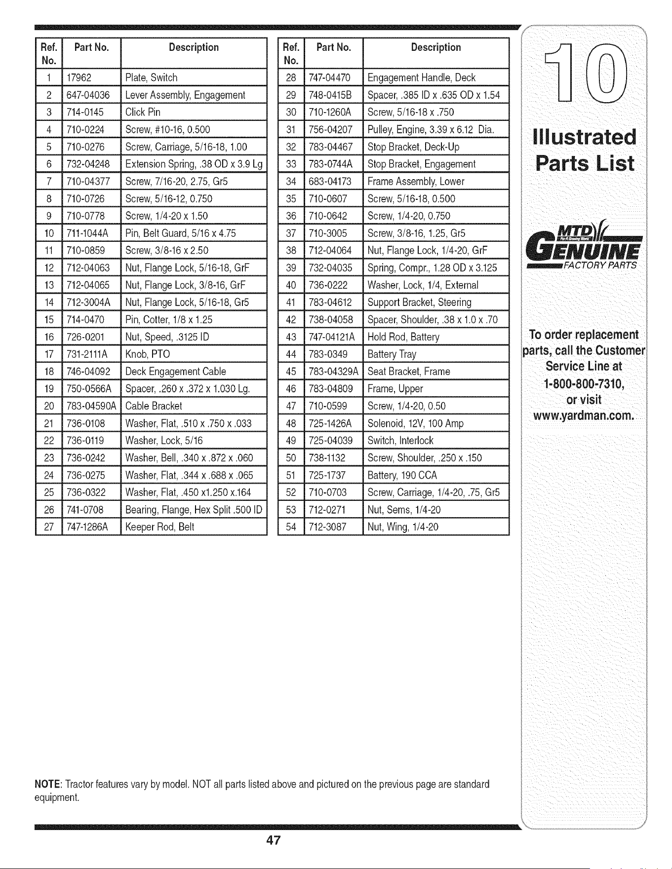
Fief. PartNo. Description
No.
1 17962 Plate,Switch
2 647-04036 LeverAssembly,Engagement
3 714-0145 Click Pin
4 710-0224 Screw,#10-16,0.500
5 710-0276 Screw,Carriage,5/16-18,1.00
6 732-04248 ExtensionSpring,.38OD x 3.9 Lg
7 710-04377 Screw,7/16-20,2.75, Gr5
8 710-0726
9 710-0778
10 711-1044A
11 710-0859
12 712-04063
13 712-04065
14 712-3004A
Fief. PartNo. Description
No.
28 747-04470 EngagementHandle,Deck
29 748-0415B Spacer,.385 IDx .635ODx 1.54
30 710-1260A Screw,5/16-18x.750
31 756-04207 Pulley,Engine,3.39x 6.12 Dia.
32 783-04467 StopBracket,Deck-Up
33 783-0744A StopBracket,Engagement
34 683-04173 FrameAssembly,Lower
35 710-0607
36 710-0642
37 710-3005
38 712-04064
39 732-04035
40 736-0222
41 783-04612
Screw,5/16-12,0.750
Screw,1/4-20x 1.50
Pin, BeltGuard,5/16x 4.75
Screw,3/8-16x 2.50
Nut, FlangeLock,5/16-18,GrF
Nut, FlangeLock,3/8-16,GrF
Nut, FlangeLock,5/16-18,Gr5
Screw,5/16-18,0.500
Screw,1/4-20,0.750
Screw,3/8-16,1.25,Gr5
Nut,FlangeLock,1/4-20,GrF
Spring,Compr.,1.28ODx 3.125
Washer,Lock, 1/4,External
SupportBracket,Steering
15 714-0470 Pin,Cotter, 1/8x 1.25
16 726-0201 Nut, Speed,.3125ID
17 731-2111A Knob,PTO
18 746-04092 Deck EngagementCable
19 750-0566A Spacer,.260x.372x 1.030Lg.
20 783-04590A CableBracket
21 736-0108 Washer,Fiat,.510x .750x .033
22 736-0119 Washer,Lock,5/16
23 736-0242 Washer,Bell,.340x .872x .060
24 736-0275 Washer,Fiat,.344x .688x .065
25 736-0322 Washer,Fiat,.450x1.250x.164
26 741-0708 Bearing,Flange,Hex Split.500 ID
27 747-1286A KeeperRod,Belt
42 738-04058 Spacer,Shoulder,.38x 1.0x.70
43 747-04121A HoldRod, Battery
44 783-0349 BatteryTray
45 783-04329A SeatBracket,Frame
46 783-04809 Frame,Upper
47 710-0599 Screw,1/4-20,0.50
48 725-1426A Solenoid,12V,100Amp
49 725-04039 Switch,Interlock
• L
50 738-1132 Screw,Shoulder,.250x.150
51 725-1737 Battery,190CCA
52 710-0703 Screw,Carriage,1/4-20,.75, Gr5
53 712-0271 Nut,Seres,1/4-20
54 712-3087 Nut,Wing, 1/4-20
NOTE:Tractorfeaturesvary by model.NOTall partslistedaboveandpicturedonthe previouspagearestandard
equipment.
47
illustrated
Parts List
I
A MTO f/
p _lmlmlmllmlm
£NUIN£
_FACTORY PARTS
Too,d ,,op .oo.,oot
parts, call the Customer
Service Line at
1-800-800,7310,
orvisit
www.yardman.com.
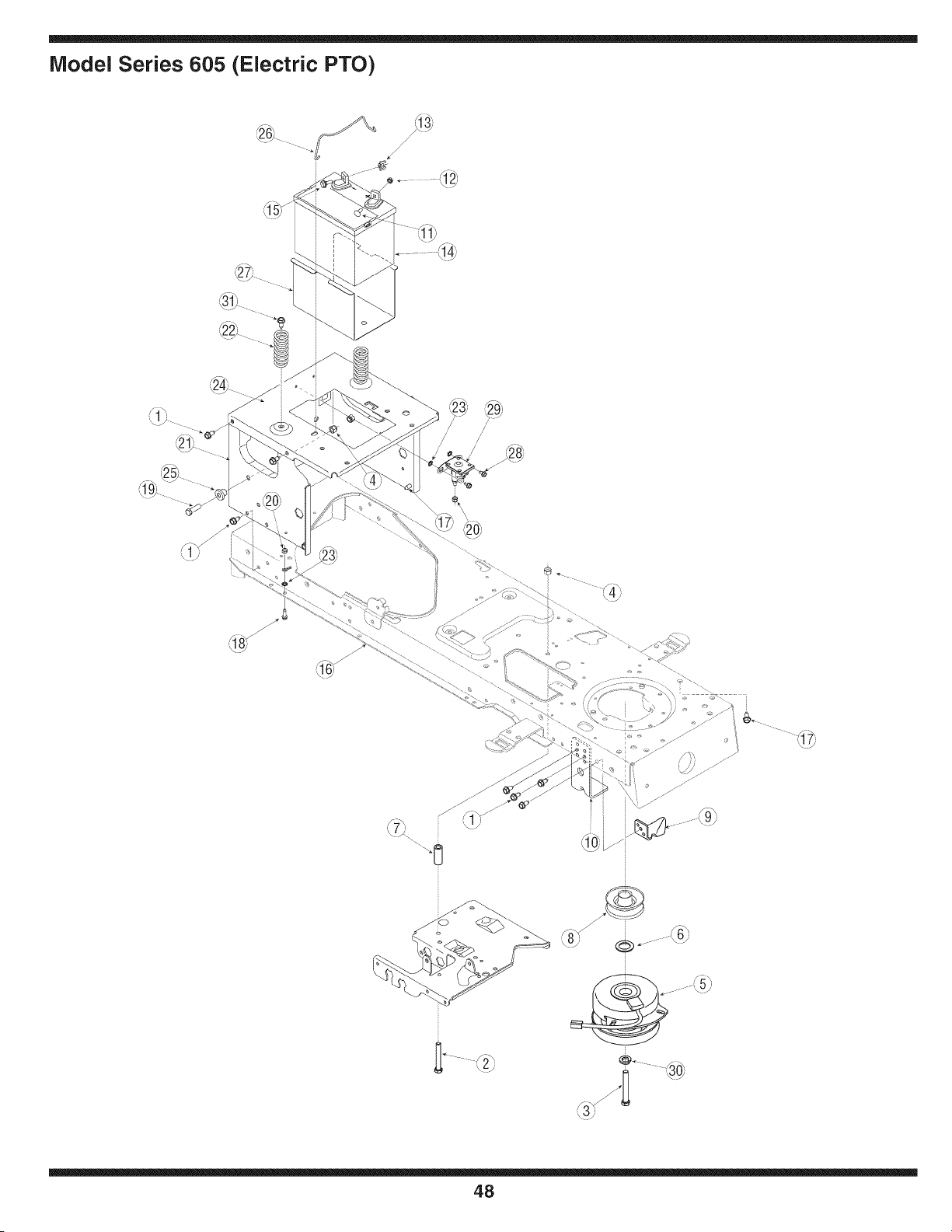
Model Series 605 (Electric PTO)
\
48
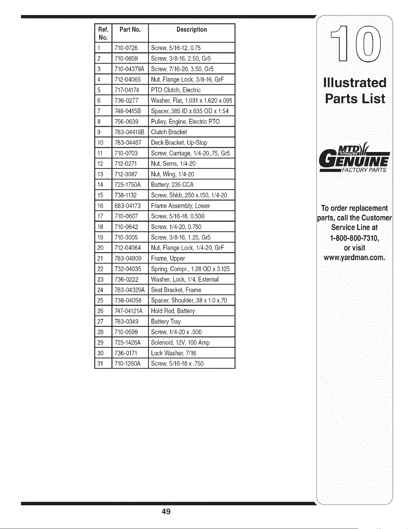
Ref. PartNo. Description
No.
1 710-0726 Screw,5/16-12,0.75
2 710-0859 Screw,3/8-16, 2.50,Gr5
3 710-04379A Screw,7/16-20,3.50,Gr5
4 712-04065 Nut,FlangeLock,3/8-16,GrF
5 717-04174 PTOClutch,Electric
6 736-0277 Washer,Flat, 1.031x 1.620x.095
7 748-0415B Spacer,.385ID x.635 ODx 1.54
8 756-0639 Pulley,Engine,ElectricPTO
9 783-04419B ClutchBracket
10 783-04467 DeckBracket,Up-Stop
11 710-0703 Screw,Carriage,1/4-20,.75,Gr5
12 712-0271 Nut,Seres,1/4-20
13 712-3087 Nut,Wing,1/4-20
14 725-1750A Battery,235 CCA
15 738-1132 Screw,Shldr,.250x.150,1/4-20
16 683-04173 FrameAssembly,Lower
17 710-0607 Screw,5/16-18,0.500
18 710-0642 Screw,1/4-20,0.750
19 710-3005 Screw,3/8-16,1.25,Gr5
20 712-04064 Nut,FlangeLock,1/4-20,GrF
21 783-04809 Frame,Upper
22 732-04035 Spring,Compr.,1.28OD x 3.125
23 736-0222 Washer,Lock, 1/4,External
24 783-04329A SeatBracket,Frame
25 738-04058 Spacer,Shoulder,.38x 1.0x.70
26 747-04121A HoldRod, Battery
27 783-0349 BatteryTray
28 710-0599 Screw,1/4-20x .500
29 725-1426A Solenoid,12V,100Amp
30 736-0171 LockWasher,7/16
31 710-1260A Screw,5/16-18x .750
ii ii _ ii i iii i ii I ii
To order replacement
parts, call the Customer
Service Line at
1-800-800-7310,
or visit
www.yardman.com.
49
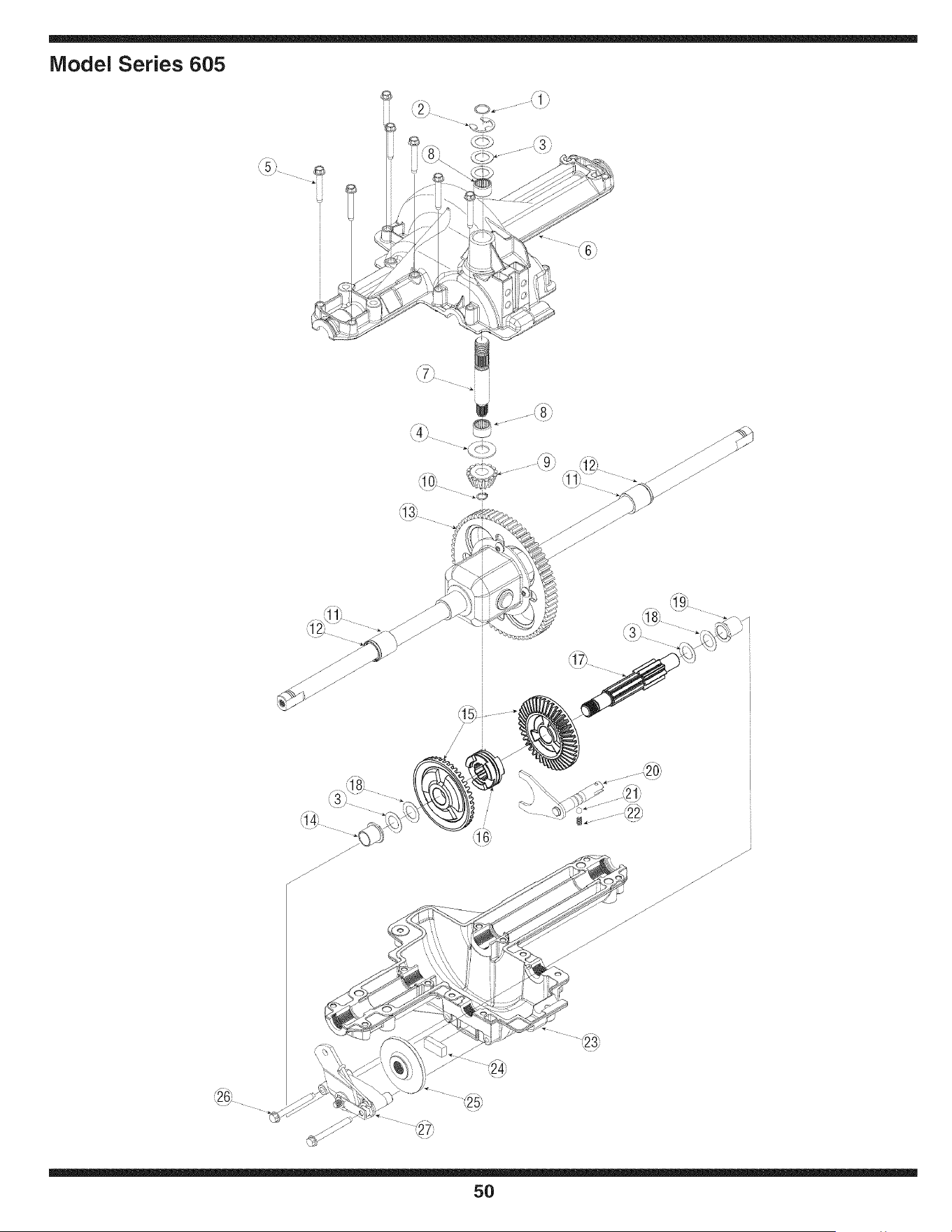
Model Series 605
5) _
[[
...._3j
<:0_...... -
[
• .° _ _, 8/I
\s
/
/
50
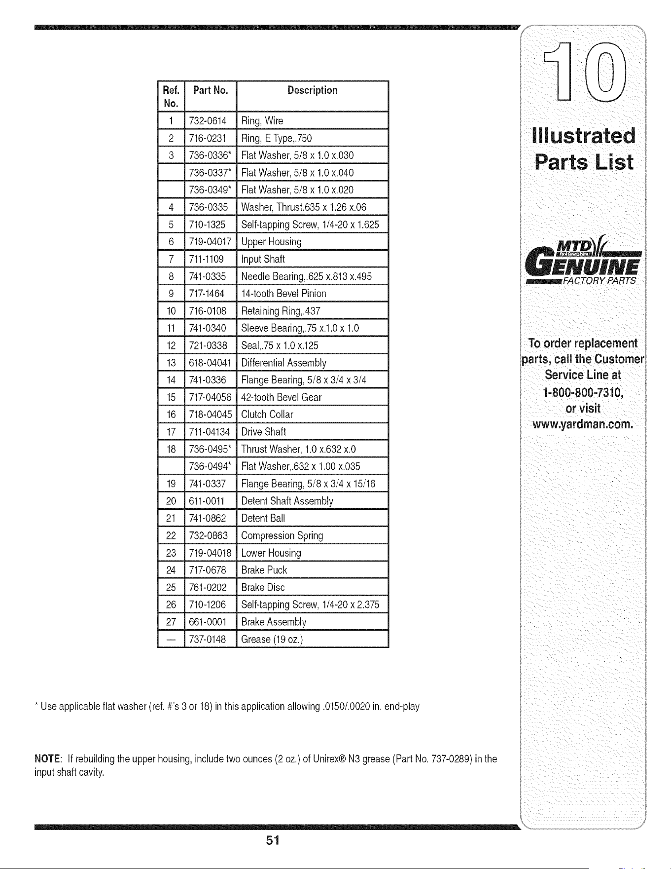
Ref. Part No. Description
No.
1 732-0614 Ring,Wire
2 716-0231 Ring, E Type,.750
3 736-0336" FlatWasher,5/8 x 1.0x.030
736-0337" FlatWasher,5/8 x 1.0x.040
736-0349" FlatWasher,5/8 x 1.0x.020
4 736-0335 Washer,Thrust.635x 1.26x.06
5 710-1325 Self-tappingScrew,1/4-20x 1.625
6 719-04017 UpperHousing
7 711-1109 inputShaft
8 741-0335 NeedleBearing,.625x.813x.495
9 717-1464 14-toothBevelPinion
10 716-0108 RetainingRing,.437
11 741-0340 SleeveBearing,.75x.l.0 x 1.0
12 721-0338 Seal,.75x 1.0x.125
13 618-04041 DifferentialAssembly
14 741-0336 FlangeBearing,5/8 x 3/4 x 3/4
15 717-04056 42-toothBevelGear
16 718-04045 ClutchCollar
17 711-04134 DriveShaft
18 736-0495* ThrustWasher,1.0x.632x.O
736-0494* FiatWasher,.632x 1.00x.035
19 741-0337 FlangeBearing,5/8 x 3/4 x 15/16
20 611-0011 DetentShaftAssembly
21 741-0862 DetentBall
22 732-0863 CompressionSpring
23 719-04018 LowerHousing
24 717-0678 BrakePuck
25 761-0202 BrakeDisc
26 710-1206 Self-tappingScrew,1/4-20x2.375
27 661-0001 BrakeAssembly
-- 737-0148 Grease(19oz.)
* Useapplicableflat washer(ref.#'s 3 or 18)inthis applicationallowing.0150/.0020in.end-play
NOTE: If rebuildingtheupper housing,includetwoounces(2 oz.) of Unirex®N3grease(Part No.737-0289)in the
input shaftcavity.
51
MTV
I
KNUINK
_FACTORY PARTS
To order replacement
parts, call the Customer
Service Line at
1-800-800-7310,
or visit
www.yardman.com.
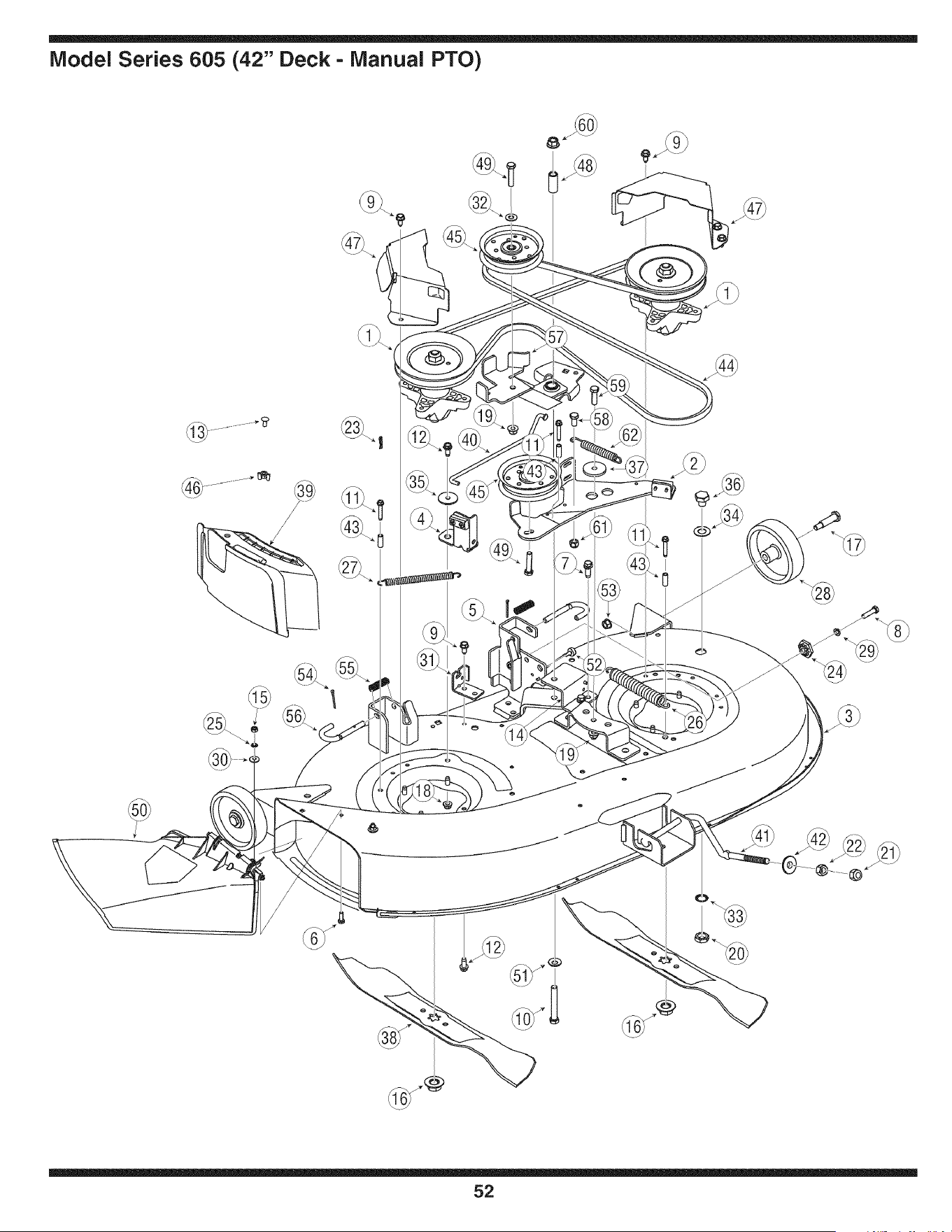
Model Series 605 (42" Deck - Manual PTO)
@
@
52
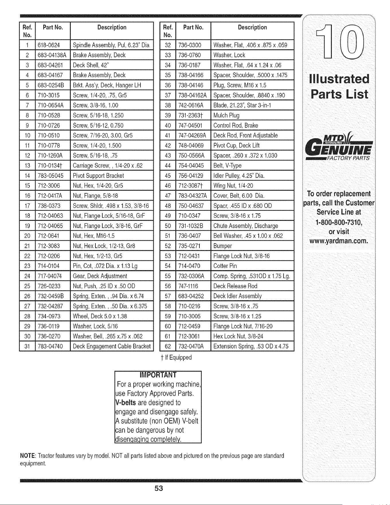
Fief. PartNo. Description
No.
1 618-0624 SpindleAssembly,Pul,6.23" Dia
2 683-04138A BrakeAssembly,Deck
3 683-04261 Deck Shell,42"
4 683-04167 BrakeAssembly,Deck
5 683-0254B Brkt. Ass'y,Deck,HangerLH
6 710-3015 Screw,1/4-20,.75,Gr5
7 710-0654A Screw,3/8-16, 1.00
8 710-0528 Screw,5/16-18,1.250
9 710-0726 Screw,5/16-12,0.750
10 710-0510 Screw,7/16-20,3.00,Gr5
11 710-0778 Screw,1/4-20,1.500
12 710-1260A Screw,5/16-18,.75
13 710-01341- CarriageScrew,, 1/4-20x .62
14 783-05045 Pivot SupportBracket
15 712-3006 Nut, Hex,1/4-20,Gr5
16 712-0417A Nut, Flange,5/8-18
17 738-0373 Screw,Shldr,.498x 1.53,3/8-16
18 712-04063 Nut, FlangeLock,5/16-18,GrF
19 712-04065 Nut, FlangeLock,3/8-16,GrF
20 712-0641 Nut, Hex,M16-1.5
21 712-3083 Nut, HexLock,1/2-13,Gr8
22 712-0206 Nut, Hex,1/2-13,Gr5
23 714-0104 Pin, Cot,.072Dia.x 1.13Lg
24 717-04074 Gear,DeckAdjustment
25 726-0233 Nut, Push,.25 IDx.50 OD
• 26 _732-0459B _Spring,Exten:,.94 D!a:x6:74
27 732-04287 Spring,Exten., .50Dia. x 6.375
28 734-0973 Wheel,Deck5.0 x 1.38
29 736-0119 Washer,Lock,5/16
30 736-0270 Washer,Bell,.265x.75x.062
31 783-04740 Deck EngagementCableBracket
Ref. Part No. Description
No.
32 736-0300 Washer,Flat, .406x .875x .059
33 736-0760 Washer,Lock
34 736-0187 Washer,Flat, .64x 1.24x .06
35 738-04166 Spacer,Shoulder,.5000x.1475
36 738-04146 Plug,Screw,M16x 1.5
37 738-04162A Spacer,Shoulder,.8840x.190
38 742-0616A Blade,21.23",Star3-in-1
39 731-23631- MulchPlug
40 747-04501 ControlRod, Brake
41 747-04269A DeckRod,FrontAdjustable
42 748-04069 PivotCup, DeckLift
43 750-0566A Spacer,.260 x.372 x 1.030
44 754-04045 Belt, V-Type
45 756-04129 Idler Pulley,4.25" Dia.
46 712-30871- WingNut, 1/4-20
47 783-04327A Cover,Belt,6.00 Dia.
48 750-04637 Spacr,.455IDx .680OD
49 710-0347 Screw,3/8-16x 1.75
50 731-1032B ChuteAssembly,Discharge
51 736-0407 BellWasher,.45x 1.00x .062
52 735-0271 Bumper
53 712-0431 FlangeLockNut,3/8-16
54 714-0470 CotterPin
55 732-0306A Comp.Spring,.5310D x 1.75Lg.
56 747-1116 DeckReleaseRod
57 683-04252 DeckldlerAssembly
710-0216 Screw,3/8-16x .75
710-3005 Screw,3/8-16x 1.25
712-0459 FlangeLockNut, 7/16-20
712-3061 HexLock Nut,3/8-24
732-0470A ExtensionSpring,.53 OD x 4.75
58
59
60
61
62
1 If Equipped
iMPORTANT
Fora properworking machine
Jse FactoryApproved Parts.
V-belts are designed to
_ngageand disengage safely.
_,substitute (non OEM) V-belt
_'anbe dangerous by not
disen a in com letel.
NOTE:Tractorfeaturesvary by model.NOTall partslistedaboveandpicturedonthe previouspagearestandard
equipment.
53
ill us t rated
Parts List
i ii i i
_FACTORY PARTS
To order replacement
parts, call the Customer
Service Line at
1-800..800=731&
or visit
www,yardman:com:
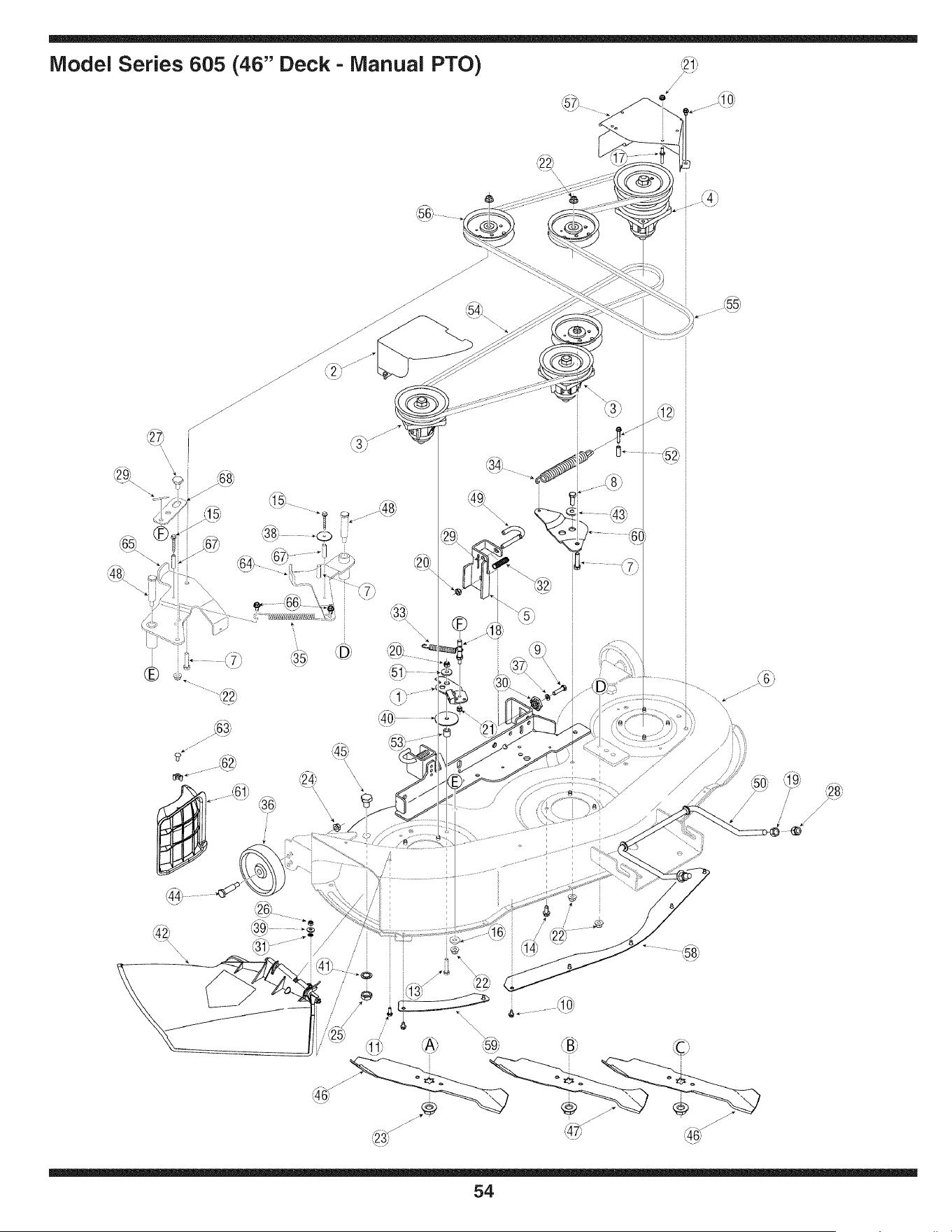
Model Series 605 (46" Deck - Manual PTO)
1
,_5__ ......
_L
®
\\\\
i
/ /
l
/ /
54
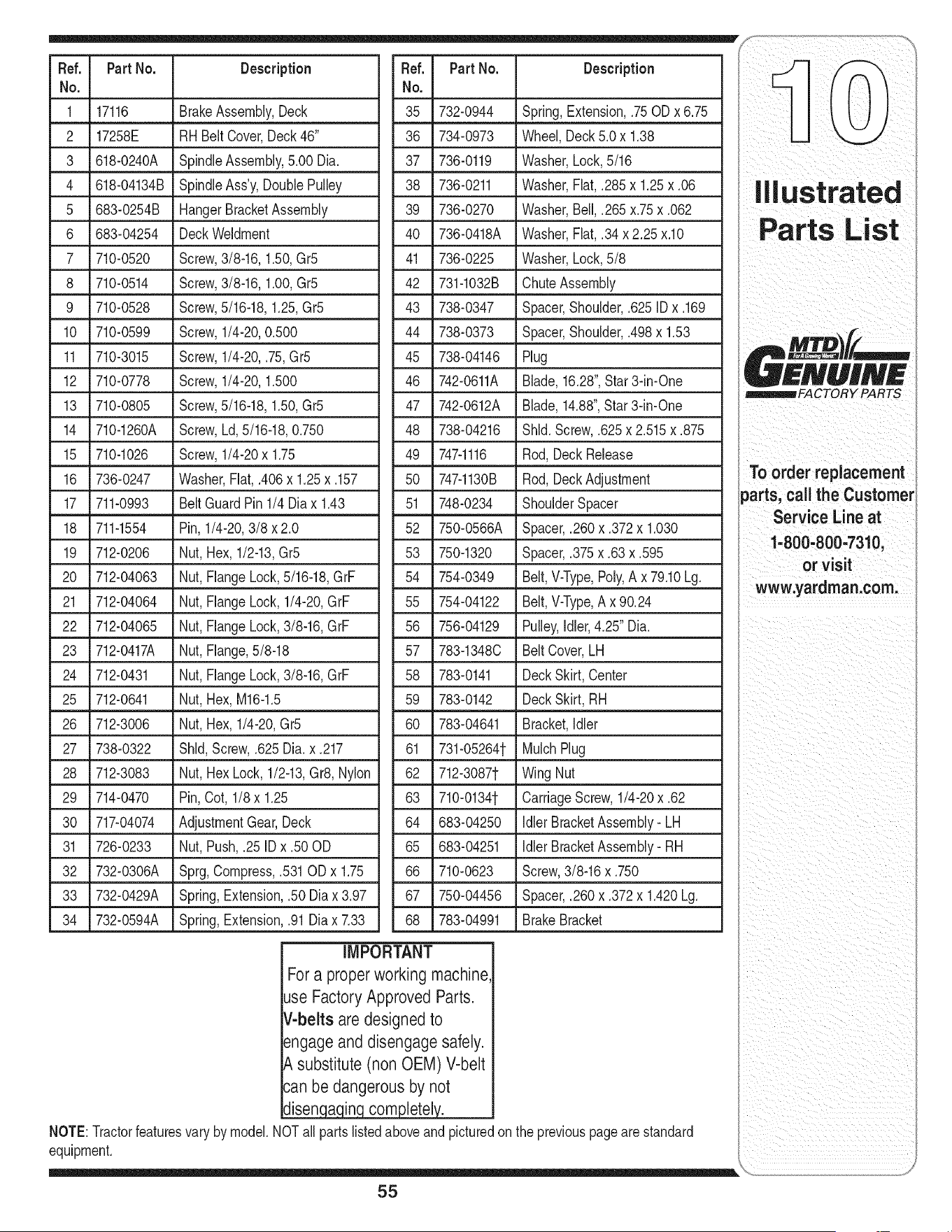
Fief. PartNo. Description
No.
1 17116 BrakeAssembly,Deck
2 17258E RHBelt Cover,Deck46"
3 618-0240A SpindleAssembly,5.00 Dia.
4 618-04134B SpindleAss'y,DoublePulley
5 683-0254B HangerBracketAssembly
6 683-04254 DeckWeldment
7 710-0520 Screw,3/8-16,1.50,Gr5
8 710-0514 Screw,3/8-16,1.00,Gr5
9 710-0528 Screw,5/16-18,1.25,Gr5
10 710-0599 Screw,1/4-20,0.500
11 710-3015 Screw,1/4-20,.75, Gr5
12 710-0778 Screw,1/4-20,1.500
13 710-0805 Screw,5/16-18,1.50,Gr5
14 710-1260A Screw,Ld, 5/16-18,0.750
15 710-1026 Screw,1/4-20x 1.75
16 736-0247 Washer,Fiat,.406x 1.25x .157
17 711-0993 Belt GuardPin 1/4 Diax 1.43
Pin, 1/4-20,3/8 x 2.0
Nut, Hex,1/2-13,Gr5
Nut, FlangeLock,5/16-18,GrF
Nut, FlangeLock, 1/4-20,GrF
Nut, FlangeLock,3/8-16,GrF
Nut, Flange,5/8-18
Nut, FlangeLock,3/8-16,GrF
Nut, Hex,M16-1.5
Nut, Hex,1/4-20,Gr5
Shld,Screw,.625 Dia.x .217
Nut, HexLock,1/2-13,Gr8,Nylon
29 Pin,Cot, 1/8 x 1.25
30 AdjustmentGear,Deck
31 Nut, Push,.25 IDx .50OD
32 Sprg,Compress,.531ODx 1.75
33 Spring,Extension,.50 Diax 3.97
34 732-0594A Spring,Extension,.91Diax 7.33
18 711-1554
19 712-0206
20 712-04063
21 712-04064
22 712-04065
23 712-0417A
24 712-0431
25 712-0641
26 712-3006
27 738-0322
28 712-3083
714-0470
717-04074
726-0233
732-0306A
732-0429A
Fief.
No.
35
36
37
38
39
40
41
42
Part No. Description
732-0944 Spring,Extension,.75 ODx 6.75
Wheel,Deck5.0 x 1.38
Washer,Lock,5/16
Washer,Fiat,.285x 1.25x .06
Washer,Bell,.265 x.75x .062
Washer,Fiat,.34 x 2.25 x.lO
Washer,Lock,5/8
ChuteAssembly
734-0973
736-0119
736-0211
736-0270
736-0418A
736-0225
731-1032B
43 738-0347 Spacer,Shoulder,.625 IDx .169
44 738-0373 Spacer,Shoulder,.498x 1.53
45 738-04146 Plug
46 742-0611A Blade,16.28",Star3-in-One
47 742-0612A Blade,14.88",Star3-in-One
48 738-04216 Shld.Screw,.625x 2.515x .875
49 747-1116 Rod,Deck Release
50 747-1130B Rod,DeckAdjustment
51 748-0234 ShoulderSpacer
52 750-0566A Spacer,.260x.372 x 1.030
53 750-1320 Spacer,.375x.63 x.595
54 754-0349 Belt,V-Type,Poly,A x 79.10Lg.
55 754-04122 Belt,V-Type,Ax 90.24
56 756-04129 Pulley,Idler,4.25"Dia.
57 783-1348C BeltCover,LH
58 783-0141 DeckSkirt,Center
59 783-0142 DeckSkirt, RH
60 783-04641 Bracket,Idler
61 731-05264t MulchPlug
62 _7123087t LWing Nut
63 710-0134t CarriageScrew,1/4-20x.62
64 683-04250 IdlerBracketAssembly- LH
65 683-04251 IdlerBracketAssembly- RH
66 710-0623 Screw,3/8-16x.750
67 750-04456 Spacer,.260x.372x 1.420Lg.
68 783-04991 BrakeBracket
IMPORTANT
For a properworking machine
use FactoryApproved Parts.
V-belts are designed to
engage and disengage safely.
A substitute (non OEM) V-belt
can be dangerous by not
disen a in com letel.
NOTE:Tractorfeaturesvary by model.NOTall partslistedaboveandpicturedonthe previouspagearestandard
equipment.
55
Illustrated
To order replacement
parts, call the Customer
Service Line at
1.800_800=7310,
or visit
www,yardman:com:
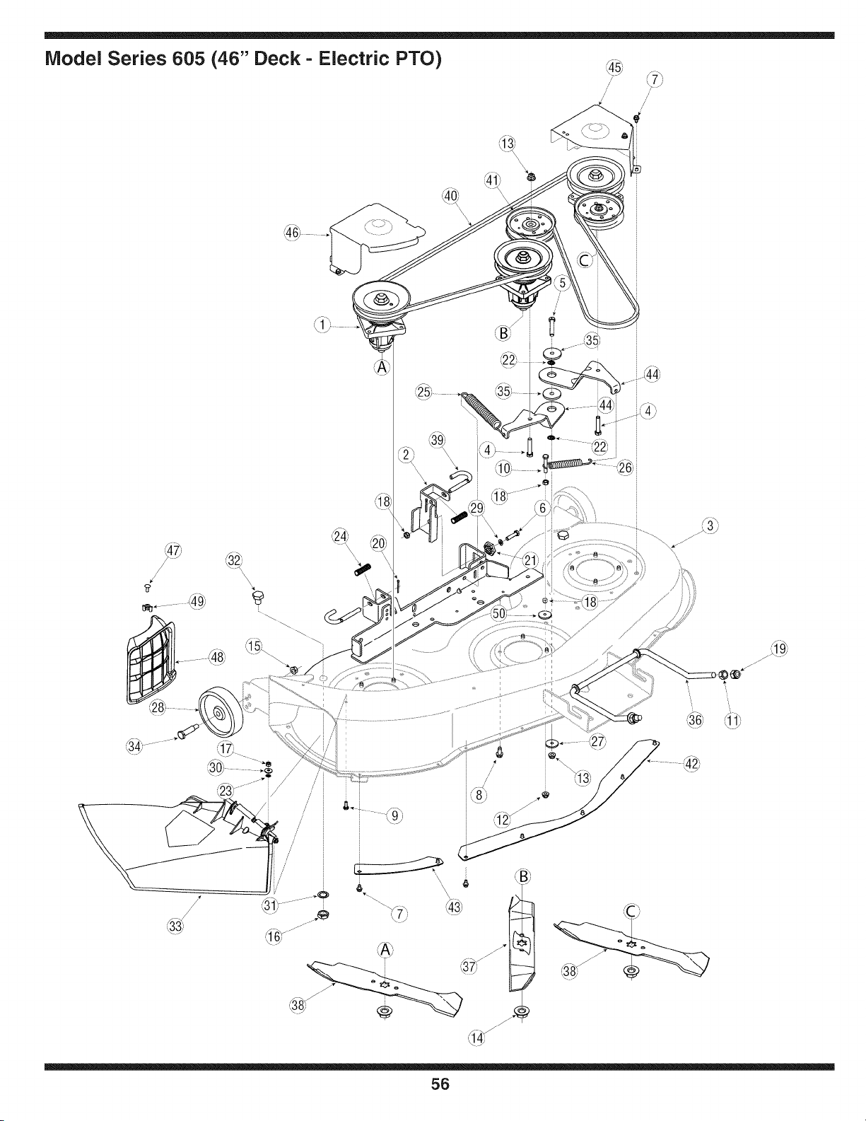
Model Series 605 (46" Deck - Electric PTO)
/
/
/
/
//
J
/
/
\\
/
/
®
f ,-,,
// -
_*"
\ ,7
56
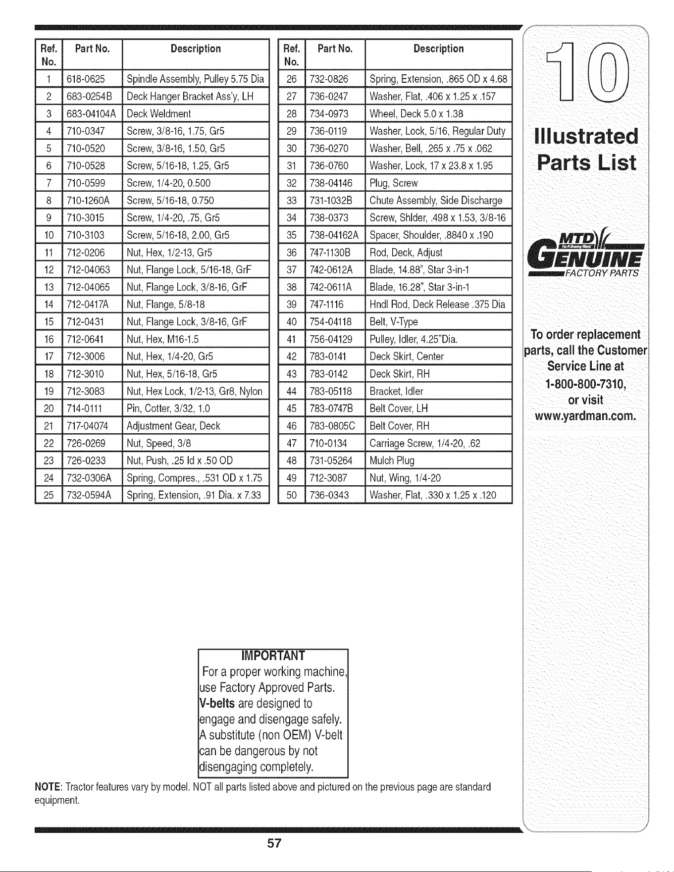
Ref. PartNo. Description Ref. Part No. Description
No. No.
1 618-0625 SpindleAssembly,Pulley5.75 Dia 26 732-0826 Spring,Extension,.865 ODx 4.68
2 683-0254B DeckHangerBracketAss'y,LH
3 683-04104A DeckWeldment
4 710-0347 Screw,3/8-16,1.75,Gr5
5 710-0520 Screw,3/8-16,1.50,Gr5
6 710-0528 Screw,5/16-18,1.25,Gr5
7 710-0599 Screw,1/4-20,0.500
8 710-1260A Screw,5/16-18,0.750
9 710-3015 Screw,1/4-20,.75,Gr5
10 710-3103 Screw,5/16-18,2.00,Gr5
11 712-0206 Nut, Hex,1/2-13,Gr5
12 712-04063 Nut, FlangeLock,5/16-18,GrF
13 712-04065 Nut, FlangeLock,3/8-16,GrF
14 712-0417A Nut, Flange,5/8-18
15 712-0431 Nut, FlangeLock,3/8-16,GrF
16 712-0641 Nut, Hex,M16-1.5
17 712-3006 Nut, Hex,1/4-20,Gr5
18 712-3010 Nut, Hex,5/16-18,Gr5
19 712-3083 Nut, HexLock,1/2-13,Gr8,Nylon
20 714-0111 Pin,Cotter,3/32, 1.0
21 717-04074 AdjustmentGear,Deck
22 726-0269 Nut,Speed,3/8
23 726-0233 Nut, Push,.25 Id x .50 OD
24 732-0306A Spring,Compres.,.531ODx 1.75
25 732-0594A Spring,Extension,.91Dia. x 7.33
27 736-0247 Washer,Fiat,.406x 1.25x .157
28 734-0973 Wheel, Deck5.0x 1.38
29 736-0119 Washer,Lock,5/16, RegularDuty
30 736-0270 Washer,Bell,.265 x .75x .062
31 736-0760 Washer,Lock,17 x 23.8x 1.95
32 738-04146 Plug,Screw
33 731-1032B ChuteAssembly,SideDischarge
34 738-0373 Screw,Shlder,.498x 1.53,3/8-16
35 738-04162A Spacer,Shoulder,.8840x.190
36 747-1130B Rod,Deck,Adjust
37 742-0612A Blade,14.88",Star3-in-1
38 742-0611A Blade,16.28",Star3-in-1
39 747-1116 HndlRod,DeckRelease.375Dia
40 754-04118 Belt,V-Type
41 756-04129 Pulley,idler,4.25"Dia.
42 783-0141 DeckSkirt,Center
43 783-0142 DeckSkirt,RH
44 783-05118 Bracket,Idler
45 783-0747B BeltCover,LH
46 783-0805C BeltCover,RH
47 710-0134 CarriageScrew,1/4-20,.62
48 731-05264 MulchPlug
49 712-3087 Nut,Wing,1/4-20
50 736-0343 Washer,Fiat,.330x 1.25x .120
IMPORTANT
Fora properworking machine
Jse FactoryApproved Parts.
V-beltsare designed to
angageand disengage safely.
_,substitute (non OEM) V-belt
:an be dangerous by not
Jisengagingcompletely_
NOTE:Tractorfeaturesvary by model.NOTall partslistedaboveandpicturedonthe previouspagearestandard
equipment.
57
!iii!ili_i_iiiiiii__i_i!i_(_i ___ i_iii_!_iiiiiiii_it
_FACTORY PARTS
Toorder replacement
parts,call the Customer
Service Line at
1.800,800=7310,
or visit
www,yardman:com:

i_il i_i i i _II _i _ i _ i i ii
,i!_ii_i_i!i_ii_ii_!_i_i_ii_i_i_i_i_i_i_i_i_i_i_i_i_i_i_i_i_I
58
CALIFORNIA EMISSION CONTROL WARRANTY STATEMENT
YOUR WARRANTY RIGHTS AND OBLIGATIONS
The CaliforniaAir ResourcesBoardandMTDConsumerGroup Inc are pleasedto explaintheevaporativeemissioncontrolsystemwarrantyon your 2006 lawn
mower.In California,new lawnmowermust be designed,builtand equippedto meet theState's stringentanti-smogstandards.MTDConsumerGroupInc must
warrantthe EECSon yourlawn mowerfor the periodof time listedbelow providedthere has beenno abuse,neglector impropermaintenanceof your lawnmower.
Your EECSmayincludeparts such as thecarburetor,fuel-injectionsystem,the ignitionsystem,catalyticconverter,fuel tanks,fuel lines,fuel caps,valves,
canisters,filters,vapor hoses,clamps,connectors,and otherassociatedemission-relatedcomponents.
Where a warrantable condition exists, MTDConsumer Group Inc will repair your lawn mower at no cost to you includingdiagnosis, parts and labor.
MANUFACTURER'S WARRANTY COVERAGE:
Thisevaporativeemissioncontrolsystemis warrantedfor two years.If any evaporativeemission-relatedpart on yourequipmentis defective,the partwill be
repairedor replacedby MTDConsumerGroup Inc.
OWNER'S WARRANTY RESPONSIBILITIES:
Asthe lawn mowerowner,you are responsiblefor performanceof the requiredmaintenancelistedin yourowner'smanual. MTDConsumerGroupIncrecom-
mendsthat you retainall receiptscoveringmaintenanceon your lawnmower,but MTDConsumerGroup Inccannot denywarrantysolelyforthe lack of receipts.
Asthe lawn mowerowner,you shouldhoweverbeawarethat MTDConsumerGroupInc maydeny you warrantycoverageif your lawnmoweror a part hasfailed
dueto abuse,neglect, orimpropermaintenanceor unapprovedmodifications.
Youare responsiblefor presentingyourlawn mowerto MTDConsumerGroupInc's distributioncenteror servicecenteras soonas the problemexists.The
warrantyrepairsshouldbe completedin a reasonableamountof time, notto exceed30 days. If you havea questionregardingyour warrantycoverage,you should
contactthe MTDConsumerGroupIncService Departmentat 1-800-800-7310.
GENERAL EMISSIONS WARRANTY COVERAGE:
MTDConsumerGroupIncwarrantsto the ultimatepurchaserand eachsubsequentpurchaserthat the lawnmower is: Designed,built andequippedso as to
conformwithall applicableregulations;andfree from defectsin materialsand workmanshipthat causethe failure of a warrantedpart to be identicalin all material
respectsto that part as describedin MTDConsumerGroupInc'sapplicationfor certification.
The warrantyperiodbeginson the date the lawnmoweris deliveredto an ultimatepurchaseror first placed into service.The warrantyperiodis two years.
Subjectto certain conditionsand exclusionsas statedbelow,the warrantyon emission-relatedparts is as follows:
1. Any warrantedpart that is not scheduledfor replacementas requiredmaintenanceinthe writteninstructionssupplied, is warrantedfor the warrantyperiod
statedabove. Ifthe part fails duringthe period of warrantycoverage,the part willbe repairedor replacedby MTDConsumerGroupInc accordingto subsection
(4) below. Anysuch part repairedor replacedunderwarrantywillbe warrantedfor the remainderof the period.
2. Any warrantedpart that is scheduledonly for regularinspection inthe writteninstructionssupplied is warrantedfor thewarranty periodstated above.Any such
part repairedor replacedunderwarrantywill be warrantedfor the remainingwarrantyperiod.
3. Any warrantedpart that is scheduledfor replacementas requiredmaintenancein thewritten instructionssuppliedis warrantedforthe periodof time beforethe
first scheduledreplacementdatefor that part. If the partfails beforethe first scheduledreplacement,the part will be repairedor replacedby MTDConsumer
GroupInc accordingto subsection(4) below.Any such part repairedor replacedunderwarrantywill be warrantedforthe remainderof the periodpriorto the
first scheduledreplacementpointfor the part.
4. Repairor replacementof any warrantedpart underthe warrantyprovisionshereinmustbe performedat a warrantystationat no chargeto theowner.
5. Notwithstandingthe provisionsherein,warrantyservicesorrepairswill be providedat all of our distributioncentersthat arefranchisedto servicethe subject
enginesor equipment.
6. The lawnmowerowner will not bechargedfor diagnosticlaborthat is directlyassociatedwithdiagnosisof a defective,emission-relatedwarrantedpart,
providedthat such diagnosticwork is performedat a warrantystation.
7. MTDConsumerGroupInc is liablefor damagesto otherengine or equipmentcomponentsproximatelycausedby a failure underwarrantyof any warranted
part.
8. Throughoutthe lawnmowerwarrantyperiodstated above,MTDConsumerGroup Incwill maintaina supplyof warrantedparts sufficientto meetthe expected
demandfor such parts.
9. Any replacementpart may be usedinthe performanceof any warrantymaintenanceor repairsand mustbe providedwithoutchargeto the owner.Suchuse will
notreducethe warrantyobligationsof MTDConsumerGroupInc.
10.Add-onor modifiedpartsthat are notexemptedbythe Air ResourcesBoardmay not beused.The useof any non-exemptedadd-onor modifiedparts by the
ultimatepurchaserwillbe groundsfor disallowinga warrantyclaims. MTDConsumerGroup Incwill notbe liableto warrantfailuresof warrantedparts caused
bythe useof a non-exemptedadd-onor modifiedpart.
WARRANTED PARTS:
The repairor replacementof any warrantedpart otherwiseeligiblefor warrantycoveragemaybe excludedfrom such warrantycoverageif MTDConsumerGroup
Inc demonstratesthat the lawnmowerhas been abused,neglected,or improperlymaintained,andthat such abuse, neglect,or impropermaintenancewasthe
directcauseof the needfor repairor replacementof the part. That notwithstanding,any adjustmentof a componentthathas a factory installed,and properly
operating,adjustmentlimiting deviceis still eligiblefor warrantycoverage.Thefollowingemissionwarrantyparts list arecovered: FuelLine,Fuel LineClamps

MANUFACTURER'S LiMiTED WARRANTY FOR
The limitedwarrantysetforthbelowisgivenby MTDLLCwith respectto
newmerchandisepurchasedandusedin the UnitedStates,its posses-
sionsandterritories.
"MTD"warrantsthis productagainstdefectsin materialandworkmanship
for a periodof two (2) yearscommencingonthe dateof originalpurchase
andwill,at its option,repairor replace,free of charge,anypart foundto
bedefectiveinmaterialsor workmanship.This limitedwarrantyshallonly
applyif this producthas beenoperatedand maintainedin accordance
withthe Operator'sManualfurnishedwiththe product,and has not been
subjectto misuse,abuse,commercialuse,neglect,accident,improper
maintenance,alteration,vandalism,theft,fire,water,ordamagebecause
of otherperilor naturaldisaster.Damageresultingfrom the installationor
useof any part,accessoryor attachmentnotapprovedby MTDfor use
withthe product(s)coveredbythis manualwill voidyourwarrantyas to
any resultingdamage.
Normalwearpartsarewarrantedto befree fromdefectsinmaterialand
workmanshipfor a periodof thirty (30) days fromthe dateof purchase.
Normalwearpartsinclude,butare notlimitedto itemssuchas: batteries,
belts,blades,bladeadapters,grassbags,riderdeckwheels,seats, snow
throwerskidshoes,shaveplates,augerspiralrubberand tires.
HOWTO OBTAINSERVICE:Warrantyserviceis available,WITH
PROOFOF PURCHASE,throughyour localauthorizedservicedealer.To
locatethe dealerin yourarea,checkyourYellowPages,orcontactMTD
LLCat RO.Box 361131,Cleveland,Ohio44136-0019,or call 1-800-800-
7310or logon to ourWebsiteat www.mtdproducts.com.
Thislimitedwarrantydoesnot providecoveragein the followingcases:
a. Theengineor componentparts thereof.These itemsmay
carrya separatemanufacturer'swarranty.Referto applicable
manufacturer'swarrantyfor termsandconditions.
b. Logsplitterpumps,valves,andcylindershavea separateone
yearwarranty.
c. Routinemaintenanceitemssuchas lubricants,filters, blade
sharpening,tune-ups,brakeadjustments,clutch adjustments,
deckadjustments,andnormaldeteriorationof the exteriorfinish
dueto use orexposure.
d. Servicecompletedby someoneotherthanan authorizedservice
dealer.
e.
f.
g.
MTDdoes notextendany warrantyfor productssoldor
exportedoutsideof the UnitedStates,its possessionsand
territories,exceptthosesoldthroughMTD'sauthorized
channelsof exportdistribution.
Replacementpartsthatarenot genuineMTDparts.
Transportationchargesand servicecalls.
No impliedwarranty, includingany impliedwarranty of merchant-
ability of fitness for a particularpurpose,applies after the applicable
periodof express written warranty above as to the partsas identi-
fied. No other express warranty, whether written or oral, except as
mentionedabove,given by any personor entity,includinga dealer
or retailer,with respect to any product,shallbind MTD. Duringthe
periodof the warranty, the exclusiveremedyis repairor replacement
of the productas setforth above.
The provisionsas setforth in this warrantyprovidethe soleand
exclusiveremedyarising from the sale.MTDshallnot be liable
for incidentalor consequentialloss or damage including,without
limitation, expensesincurredfor substituteor replacement lawn care
servicesor for rentalexpenses to temporarily replacea warranted
product.
Somestatesdo not allowtheexclusionor limitationof incidentalor
consequentialdamages,or limitationson howlonganimpliedwarranty
lasts,so the aboveexclusionsor limitationsmay notapplyto you.
In noeventshall recoveryof any kind begreaterthan theamountof the
purchasepriceof the productsold.Alterationof safety features of the
productshall void this warranty. Youassumethe risk and liability for
loss, damage,or injuryto youand your propertyand/orto others and their
propertyarisingout of the misuseor inabilityto use theproduct.
Thislimitedwarrantyshall notextendto anyoneotherthanthe original
purchaseror to the personfor whom itwaspurchasedas a gift.
HOWSTATELAWRELATESTO THISWARRANTY: Thislimitedwar-
rantygivesyouspecificlegalrights,andyou mayalso haveother rights
whichvaryfromstateto state.
IMPORTANT: OwnermustpresentOriginalProofof Purchaseto obtain
warrantycoverage.
MTD LLC, P.O. BOX 361131 CLEVELAND, OHIO 44136=0019; Phone: 1=800=800=7310