
Safety Instructions & Operator's Manual for
,SNAPPER,
LAWN TRA CTOR
HYDROSTATIC &
GEAR DRIVE
SERIES D
MODELS
GEAR DRIVE HYDROSTATIC
DRIVE
LT120G30DB LT140H33DBV
NLT120G30DB LT145H33DBV
LT125G38DB LT145H38DBV
NLT145H38DBV
I
MODEL DESIGNATION
ENGINE HP
DRIVE SYSTEM TYPE
CUTTING WIDTH
MODEL NUMBER EXPLANATION
LT I 145I H 1381 O I B I V I
i ENGINE TYPE
; ENGINE MODEL
SERIES DESIGNATION
LT - Lawn Tractor Model Designation
120 - 12.0 HP Engine Horse Power
125 - 12,5 HP Engine Horse Power
H - Hydrostatic Transmission
30 - 30" Cutting Width Mower
33 - 33" Cuttino Width Mower
140 - 14.0 HP Engine Horse Power
145 - 14.5 HP Engine Horse Power
G - Gear Drive Transmission
38 - 38" Cutting Width Mower
D - Series Designation
B - Briggs & Stratton Engine
V - Over Head Valve Type Engine
Thank you for buying a SNAPPER product! Before operating the Lawn Tractor, read and follow the
"IMPORTANT SAFETY INSTRUCTIONS" on pages 2 & 2A, all other instructions contained in this manual and
the accompanying booklet "About Power Mower Safety". "Lawn mowers and all power equipment can be
potentially dangerous ff used improperly. REMEMBER: SAFETY REQUIRES CAREFULL USE IN ACCORDANCE
WITH INSTRUCTIONS AND COMMON SENSE/.
COPYRIGHT © 1998
SNAPPER NC
ALL RIGHTS RESERVED
MANUAL No. 3-5576 (REV. 2, 6/98)

IMPORTANT SAFETY INSTRUCTIONS
WARNING: This powerful cutting machine is capable of amputating hands and feet and can throw objects that
can cause injury and damage! Failure to comply with the following SAFETY instructions could result in
serious injury or death to the operator or other persons. The owner of the machine must understand these
instructions and must allow only persons who understand these instructions to operate machine. Each
person operating the machine must be of sound mind and body and must not be under the influence of any
substance which might impair vision, dexterity or judgment. If you have any questions pertaining to your
machine which your dealer cannot answer to your satisfaction, call or write the Customer Service Department
at SNAPPER, McDonough, Georgia 30253. Phone: (1-800-935-2967).
PROTECTION FOR CHILDREN
Tragic accidents can occur if the operator is not alert
to the presence of children. Children are often
attracted to the machine and the mowing activity.
Never assume that children will remain where you
last saw them.
1. KEEP children out of the mowing area and under
the watchful care of a responsible adult.
2. DO NOT allow children in yard when machine is
operated (even with the blade OFF).
3. DO NOT allow children or other passengers to
ride on machine or on attachments (even with the
blade OFF). They may fall and be seriously
injured.
4. DO NOT allow pre-teenage children to operate
machine.
5. ALLOW only responsible adults & teenagers with
mature judgment under close adult supervision to
operate machine.
6. BE SURE the area is clear of others before
mowing and turn machine OFF if anyone enters
the area.
7. DO NOT mow in reverse unless absolutely
necessary. LOOK BEHIND and down for small
children before and when backing.
8. USE EXTRA CARE when approaching blind
corners, shrubs, trees, or other objects that may
obscure vision.
PROTECTION AGAINST TIPOVERS
Slopes are a major factor related to loss-of-control
and tip-over accidents, which can result in severe
injury or death. All slopes require extra CAUTION. If
you cannot back up the slope or if you feel uneasy on
it, DO NOT mow it. Use extra care with grass catchers
or other attachments; these can change the stability
of the machine.
1. DO NOT operate machine on slopes exceeding 15
degrees (27% grade).
2. Exercise EXTREME CAUTION on slopes above 10
degrees (18% grade). Turn blade OFF when
traveling uphill. Use first speed and avoid sudden
or sharp turns.
3. DO NOT mow back and forth across face of
slopes. Mow up and down.
PROTECTION AGAINST TIPOVERS
(Continued From Previous Column)
4. AVOID uphill starts. If machine stops going uphill
or tires lose traction, turn blade OFF and back
slowly down the slope.
5. STAY ALERT for holes and other hidden hazards.
Tall grass can hide obstacles. Keep away from
ditches, washouts, culverts, fences and
protruding objects.
6. KEEP A SAFE DISTANCE (at least 3 feet) away
from edge of ditches and other drop offs. The
mower could turn over if an edge caves in.
7. Always begin forward motion in the #1 speed
position.
8. Use weights or a weighted load carrier in
accordance with instructions with a grass catcher
on slopes above 10 degrees (18% grade).
9. DO NOT put your foot on the ground to try to
stabilize the machine.
10. DO NOT mow on wet grass. Reduced traction
could cause sliding.
11. DO NOT mow under any condition where traction,
steering or stability is doubtful without first test
driving over the terrain with blade OFF.
PREPARATION
1. Read this manual, get to know where all controls
are located and practice how to use them before
starting for the first time, and at the beginning of
each season. Read and follow Warnings and
Instructions on engine and machine. Read and
follow operator's manual and instructions
furnished with attachments.
2. Only mature, responsible persons shall operate
the machine and only after proper instruction.
3. Handle fuel with extra care. Fuels are flammable
and vapors are explosive. Use only an approved
fuel container. Never remove fuel cap or add fuel
with engine running. Add fuel outdoors only with
engine stopped and cool. Clean spilled fuel from
machine. DO NOT smoke.
4. Practice operation of machine with BLADE OFF to
learn controls and develop skills.
(Continued on Next Page}

IMPORTANT SAFETY INSTRUCTIONS
PREPARATION
(Continued From Previous Page)
5. Check the area to be mowed and remove all
objects such as toys, wire, rocks, limbs and other
objects that could cause injury if thrown by blade
or interfere with mowing.
6. Keep people and pets a safe distance from
machine.
7. Check shields, deflectors, switches, blade
controls and other safety devices frequently for
proper operation and location.
8. Make sure all safety decals are clearly legible.
Replace if damaged.
9. Protect yourself when mowing and wear safety
glasses, long pants and substantial footwear.
10. Know how to STOP blade and engine quickly in
preparation for emergencies.
11. Use extra care when loading or unloading the
machine into a trailer or truck.
12. Check grass catcher components frequently for
signs of wear or deterioration and replace as
needed to prevent injury from thrown objects
going through weak or worn spots.
OPERATION
1. Mount and dismount machine from left side.
2. Start engine from operator's seat, if possible.
Make sure blade is OFF and parking brake is set.
3. STOP blade, STOP engine, set parking brake and
remove key when leaving machine.
4. DO NOT operate machine unless properly seated
with feet on feet rests or pedal(s).
5. STOP BLADE and ENGINE and make sure blade
has stopped before removing grass catcher or
unclogging mower to prevent loss of fingers or
hand.
6. Blade must be OFF except when cutting grass.
Set blade in highest position when mowing over
rough ground.
7. Keep hands and feet away from rotating blade
underneath deck. NEVER place foot on ground
while BLADE is ON or machine is in motion.
8. Deflector or entire grass catcher must be in place.
NEVER point discharge at people, passing cars,
windows or doors.
9, Slow down before turning.
MAINTENANCE
1. Never store machine or fuel container inside
where fumes may reach an open flame, spark or
pilot light such as in a water heater, furnace,
clothes dryer or other gas appliance. Allow
engine to cool before storing machine in an
enclosure. Store fuel container out of the reach of
children in a well ventilated, unoccupied building.
2. Keep engine free of grass, leaves or excess
grease to reduce fire hazard and engine
overheating.
3. When draining fuel tank, drain fuel into an
approved container outdoors and away from open
flame.
4. Check brakes frequently; adjust, repair or replace
as needed.
5. Keep all bolts, nuts and screws properly tight.
Check that all cotter pins are in proper position.
6. Always provide adequate ventilation when
running engine indoors. Exhaust gases contain
carbon monoxide, an odorless and deadly
poison.
7. Disconnect negative (black) cable from battery
before performing maintenance or service.
Cranking engine could cause injury.
8. Never work under machine without safety blocks.
9. Service engine and make adjustments only when
engine is stopped. Remove spark plug wire(s)
from spark plug(s) and secure wire(s) away from
spark plug(s).
10. DO NOT change engine governor speed settings
or overspeed engine.
11. Lubricate machine at intervals specified in
manual to prevent controls from binding.
12. Mower blades are sharp and can cut. Wrap the
blades or wear heavy leather gloves and use
CAUTION when handling them.
13. NEVER test for spark by grounding spark plug
next to spark plug hole; spark plug could ignite
gas exiting engine.
14. Have machine serviced by an authorized
SNAPPER dealer at least once a year and have the
dealer install any new safety devices.
15. Use only genuine SNAPPER replacement parts to
assure that original standards are maintained.
10. Watch out for traffic when near or crossing
roadways.
11. STOP engine immediately after striking an
obstruction. Inspect machine and repair damage
before resuming operation.
12. Mow only in daylight or with good artificial light.
13. Move joystick (if equipped) SLOWLY to maintain
control during speed and directional changes.
14. Exercise CAUTION when pulling loads. Limit
loads to those you can safely control and attach
loads to hitch plate as specified with SNAPPER
attachment instructions.
2A

TABLE OF CONTENTS
IMPORTANT SAFETY INSTRUCTIONS ...... 2 & 2A
TABLE OF CONTENTS ........................................ 3
FAMILIARIZATION ............................................. 4-5
Serial & Model Number Location ........................... 4
Controls .................................................................... 5
Components ........................................................... 5
OPERATING INSTRUCTIONS ........................ 6-11
Pre-start Checklist ................................................... 6
Adjusting Operator's Seat ....................................... 6
Starting & Stopping Engine ....................................... 7
Starting & Stopping Wheel Drive ............................... 8
Setting & Releasing Parking Brake ..........................
Starting & Stopping Mower Blades .......................... 9
Adjusting Cutting Height ......................................... 10
Raising Chute Deflector ......................................... 10
Rolling Tractor W_h Engine Off ......................... 9-10
Tips on Mowing ....................................................... 11
ACCESSORIES .................................................. 11
TROUBLESHOOTING GUIDE ....................... 12-13
MAINTENANCE INSTRUCTIONS ................. 14-35
Service Schedule ......................................... 14
Maintenance Parts ....................................... 14
Hydrostatic Transmission Oil .................... 15
To CheckOilLevel...............................................
Changing Engine Oil ................................... 16
Lubrication (Tractor] .............................. 17-18
Front Wheel Bearings ......................................... 17
Axle Spindles ....................................................... 17
Steering Shaft ...................................................... 17
Clutch/Brake Pivot............................................... 17
Steering Sector Gear .......................................... 17
Steering Drag Link .............................................. 18
Steering Tie Rod ................................................. 18
Park Brake Latch ................................................ 18
Deck Lift Mechanism .......................................... 18
Blade Engagement Mechanism ......................... 18
Engine Service ............................................. 19
Engine Air Pre-Cleaner ....................................... 19
Engine Air Cleaner .............................................. 19
Spark Plug ........................................................... 19
Fuel Filter ........................................................... 19
Engine Cooling System ...................................... 20
MAINTENANCE INSTRUCTIONS (Continued)
Battery Service ............................................. 20-21
Battery Electrolyte Check ............................ 20
Battery Charging ................................................ 21
Mower Deck Removal/Reinstallation .......... 22-23
Standard Mower Blade Service ................... 26-28
Standard Blade Wear Limits ....................... 26
Blade Removal/Replacement ...................... 26-27
33" Mower Blade ............................................ 26
38" Mower Blade ............................................ 27
Sharpening Standard Blade(s) ................ 28
Ninja Mower Blade Service .................................. 28
Ninja Blade Wear Limits................................28
Ninja Blade Sharpening .................................29
Belt Service .................................................. 21-25
Mower Drive Belt Removal/Replacement 25
33" & 38" Deck Drive Belt.............................25
Traction Drive Belt Service .................... 21-24
Traction Drive Belt Removal ......................... 23
Traction Drive Belt Replacement .................. 24
Traction Drive Belt Adjustment ................ 29-30
Deck Level Adjustment .............................. 31-33B
Side to Side Level ............ 31-32 & 33A-33B
Front to Rear Level ........................32-33 & 33B
Sector Plates..................................................32
FrontLiftRod ......................................33 & 33A
Shifter Adj ustment ............................................ 34
Steering Adjustment ......................................... 34
Wheel Brake Adjustment .................................. 35
ELECTRICAL SYSTEM ................................. 36-37
Wiring Harness Routing ...................................... 36
DIAGRAMS, Briggs Engine w/o lights................ 37
DIAGRAMS, Briggs Engine w/lights ................... 37
WARRANTY ....................................................... 38
PRIMARY MAINTENANCE ............................ 39-42

FAMILIARIZATION
H_.'t::1:! P"_IHE:I _v,(o] _] ::!mid_Ill Lv,I :1:1:1 Ko]).]P',_In/ (o]; •
The serial and model number of the SNAPPER Series D
Lawn Tractor are located on the rear face of the tractor
frame as shown in Figure 1. Record these numbers inthe
space provided. They will be useful in ordering parts or
accessories for the tractor.
!
MODEL NUMBER
SERIAL NUMBER
I
REAR VIEW
_/. !_OF _ACTOR
/ \
/
SNAPPER. McOn.p. = 3o2ss
SER XXXXXXXX MOD XXXXXXXXXXX
KW X.XX KG XXX
HP X.X LBS XXX
RPM XXXX
_iiiii_ii_ii_iiiiiii_}iiii_ii!i!_!iii_i_!__e_n_iii!i!i!i_iii!_!i!iiii_!_i_ii_i!_i_i_!
FIGURE 1
m[o{o]: ind:To] _!
NOTE: STEERING WH EEL & OPERATOR'S SEAT NOT SHOWN IN THIS VIEW.
All operator'sshould be acquaintedwith the operator's
controlsbefore attemptingstart-up or operationof the
SeriesD LawnTractor.See Figure2.
PEDAL
ENGINE SP
CONTROL
PARK BRAKE
LATCH
(HYDRO ONLY)
__W HEADLIGHT
ITCH
DECK
UFT
.°v°.
IGNITION
I_J/ SWITCH
-_ BLADE
! E_G_RGEMENT
SPEED
CONTROL
LEVER
FIGURE 2
4

FAMILIARIZATION
[_o] Lv,I ".,To]_,1:1_,b u_
The nomenclature drawings, Figures 2 & 3, illustrate the
essential components of the SNAPPER Series D Lawn
Tractor. It is recommended that all operators of this
equipment become thoroughly familiar with the compo-
nents and their operation BEFORE OPERATING. Spe-
cific details involving the engine are found in the separate
Engine Owners' Manual. Study the Important Safety
Instructions, this Operators' Manual and Engine Owners'
Manual before operating this machine. Keep these
manuals avail able for future reference.
SEAT
ADJUSTMENT
KNOB
BATTERY
(UNOER SEAR
---OPERATOR'S
SEAT
FAST_i
SLOW-_
ENGINE-_-_
SPEED
CONTROL
_ CHOKE
!
/
WHEEL /
/
.DASHBOARD
CONTROLS
FUEL TANK
(UNDER HOOD)
CHUTE
DEFLECTOR
HEADUGHTS
MOWING DECK
(33" SHOWN)
ENGINE
FIGURE 3
OPERATING INSTRUCTIONS
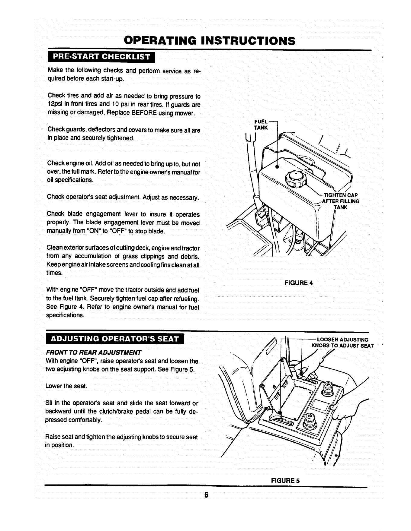
I d :! =5.'t if:! :_iI It.,].-I :(H ;I ii [..1,i
Make the followingchecks and perform serviceas re-
quiredbeforeeach start-up.
Checktires and add air as needed to bringpressure to
12psi in fronttires and 10 psi in reartires. If guardsare
missingor damaged, Replace BEFORE usingmower.
Checkguards,deflectorsand coversto makesure all are
inplaceand securelytightened.
Checkengineoil.Addoil as neededtobringupto, but not
over,thefullmark.Refertothe engineowner'smanualfor
oil specifications.
Checkoperator'sseat adjustment.Adjustas necessary.
Check blade engagement lever to insure it operates
properly.The blade engagement lever must be moved
manuallyfrom "ON" to "OFF"to stop blade.
TANK
/
CAP
_.AFTER FILLING
TANK
Clean exteriorsurfacesof cuttingdeck,engineandtractor
from any accumulation of grass clippingsand debris.
Keepengineair intake screensandcoolingfinscleanatall
times.
Withengine "OFF"move the tractoroutsideand addfuel
to the fuel tank. Securely tightenfuel cap after refueling.
See Figure 4. Refer to engine owner's manual for fuel
specifications.
FIGURE 4
FRONT TO REAR ADJUSTMENT
With engine"OFF", raise operator'sseat and loosenthe
two adjustingknobs onthe seat support.See Figure5.
Lowerthe seat.
LOOSEN ADJUSTING
KNOBS TO ADJUST SEAT
Sit in the operator's seat and slide the seat forward or
backward until the clutch/brakepedal can be fully de-
pressedcomfortably.
Raiseseatandtightenthe adjustingknobstosecureseat
inposition.
6
FIGURE 5

OPERATING INSTRUCTIONS
:,In#,I :_idI: [rl:_..'t liD] "J"JI: [tl =1_[r] I: I =i
I _
STARTING ENGINE
Take a comfortablepositionin seat of ridingmower,look
aroundto make surethat the area you are goingto mow
is clear of people, children and pets. Take note of any
stationaryobstacles!
NOTE:
The interlocksystemwillpreventthe engine from starting
ifthe blade engagementleveris in the "ON" (up)position.
If the interlocksystemeverfails to work, DO NOT OPER-
ATE the tractoruntilthe interlockhas been repaired.
Pushblade engagement leverdowntothe "OFF"position.
See Figure6.
ENGAGEMENT
LEVER
PUSH BLADE ENGAGEMENT
TO START ENGINE
\
\
FIGURE 6
Depress the clutch/brakepedal fully. See Figure7.
NOTE:
The seat interlockwill shutoff the engine ifthe operator
gets offthe seat withoutsetting the parkingbrakeleveror
ifthe bladeis running.If the interlockeverfailstowork,DO
NOT OPERATE the tractoruntil the interlockhas been
repaired.
Choke enginefor cold startingby moving engine speed DOWN
controlto "CHOKE" position. Littleor no chokingwill be '_',X _
needed when restarting a warm engine. See Figure 8.
\
Insert key inswitch.
L
Turn key to "START" position to crank engine and hold
until engine starts, then release key.
NOTE:
DO NOT crank engine for more than five secondsat a
time. This will help prevent the starterfrom overheating
an_or runningdownthe battery. Ifcrankingtime is more
than five seconds, locate and correct cause of starting
problem.
After engine starts,release key, move the engine speed
controlto the "FAST" positionandallow enginetowarmup
before proceeding.See Figure8.
STOPPING ENGINE
Turn key to "STOP". See Figure8.
FIGURE 7
CHOKE
ENGINE -_-_-._ _. _--- _--_,,_
LKEy
FIGURE 8

OPERATING INSTRUCTIONS
_._ net :_unlI: [_lr:l-_ n[o]"J"JI _[riYl: 1:1=1nl ,] ;1Lvi=
STARTING WHEEL DRIVE OF HYDRO MODELS
Shift speed controllever to neutral.
Start engine.
Release brake pedal.
Slowlyshiftspeed controlleverforwardfor forwardmotion
or to the rear for reverse motion.See Figure9.
STOPPING WHEEL DRIVE
Fully depress clutch/brake pedal to stop wheel drive.
Shift speed control lever to neutral. See Figure 10.
NOTE: (HYDRO DRIVE MODELS ONLY)
When the tractor is moving forward and the clutch/brake
pedal is pushed all the way down, the speed control
handlewillautomaticallyreturnto approximately1/3offull
forward speed. Move handle to desired positionafter
releasing brake pedal.
STARTING WHEEL DRIVE OF GEAR MODELS
Shiftspeed controlleverto neutral.
Start engine.
Fullydepressclutch/brakepedal.
Move speed controlhandle forward to Firstspeed.
See Figure 11.
Slowly release clutch/brakepedal to begin motion.
FORWARD
SPEEDS
CLUTCH/BRAKE
PEDAL
SPEED CONTROL
HANDLE
HANDLE
REVERSE
I
FIGURE 9
CLUTCH/BRAKE
PEDAL TO STOP
WHEEL MOTION
FIGURE 10
NOTE: (GEAR DRIVE MODELS ONLY)
The clutch/brake pedal must be fully depressed when
changingspeed.
FORWARD
SPEEDS
REVERSE
NEUTRAL
FIGURE 11
8

OPERATING INSTRUCTIONS
_-'lmmr.1:_mnlI _[rt::lE._m go] ..J..JI _[it L',[olV,'J=1:l :| mF_,lp]=l
STARTING MOWER BLADE
Start engine.
PULL BLADE ENGAGEMENT
LEVER UP TO "ON" TO
START MOWER BLADE(S)
ON
Raise blade engagement leverto "ON". See Figure 12.
STOPPING MOWER BLADE
Move blade engagement leverto "OFF". See Figure 12.
I_-.1:a / dI ,_[rl:Ji :t :1al:f.!,.-] I _'[rll ".,/:I:t [1:1 ::El [4::1
SETTING PARK BRAKE
ENGAGEMENT
LEVER
FIGURE 12
PEDALALL
PARK BRAKE
LEVER
Fullydepress clutch/brake pedal.
Movepark brake lever up into slot. See Figure 13.
Release clutch/brake pedal.
RELEASING PARK BRAKE
Fully depress clutch/brake pedal. The park brake lever
will release automatically.
MOVE PARK
LEVER"UP"TOENGAGE
PARK BRAKE
FIGURE 13
I :{o] ! q I _[ttl /; f-Till I[Ol:llV,'| 1111:I =1_[d I _I ::l[o]d =1
ROLLING HYDRO MODELS
ROLL RELEASE --
CONTROL
With engine "OFF", move to rearof tractor.
Movethe roll release control to the right and down. This
disengages the hydro transmission. See Figure 14.
Move tractorto desired location.
Moveroll release controlupandtothe leftto engage hydro
transmission
Set park brake.
NOTE:
The transmission will not propel the tractor if it is left in the
"ROLL" position.
\
\
\
ENGAGED
POSITION
FIGURE 14
POSITION

OPERATING INSTRUCTIONS
ROLLING GEAR DRIVE MODELS GEARDRIVEMODELSHOWN
With engine 'OFF', fullydepressclutcl_/brakepedal.
Place speed controllever in the neutral(N) position.See
Figure 15.
Release clutch/brakepedal and movetractorto desired
location.
Setparkbrakeandplacespeedcontrolleverintoaforward
speed.
m:_,_[_1I: [rl_]: t,J=i =1,]=1il _=[,, lo_ia=
/
FIGURE 15
1997 MODEL YEAR SHOWN
-SPEED
CONTROL
HANDLE
RAISING CHUTE DEFLECTOR for CLEARANCE
THROUGH GATES or TRANSPORTS
Remove wing nuts and flat washers, securing chute
deflector to deck. See Figure 16.
Raise chute deflector and reinstall flat washers and wmg
nuts onto studs to prevent loss.
Transport tractor to desired location.
Never attempt to operate mower without chute
deflector secured In the down position.
WING NUT
_,,._ FLAT WASHER
CHUTE DEFLECTOR
MUST BE IN THE "'DOWN"
POSITION BEFORE
OPERATING MOWER
FIGURE 16
i]I o_LuZ,,._dI _(_ub • dI _(_: I _ [_: b •
ADJUST CUTTING HEIGHT for all DECKS
Depresslock button on deck liftlever. See Figure17.
Raiseor lower deck to anyof six positions as desired.
DEPRESS LOCK ---I
( 15.I.oPO::_ON__s,
CUT
FIGURE 17
10

OPERATING INSTRUCTIONS
I / I ",.Z.."_l] _I ;l [*;'i'l I _[rII
For best results,use the followingtips when mowing.
When mowing,cutonly 1/3 of grassheight.Cuttinggrass
deeper couldbe harmfulto your lawn.
If cuttingextremelytall grass, make one cuttingwith the
deck in its highestcuttingposition,then lower deck to
desiredposition and a second cut.
Mow when lawnis dry.
Mow often.Shortergrassclippingsdecomposequicker.
Keep mower blades sharp. A dull blade tearsand shreds
grass instead of cutting. Your SNAPPER dealer can
sharpen blades as required.
Alternate mowing pattern to reduce the possibility of grass
matting.
Mow withenginespeed controlinthe "FAST" positionand
speed controlhandlein a "SLOW" position.
Clean deck, removing all grass clippingsanddebris from
the top and undersideof deck after each use.
V'_ltl'_1!W_.!:] il =f;_*-[*4 =b'_._*]:! I $1
The SNAPPER Series D LAWN TRACTOR can be equipped with a variety of accessories that increase its versatility.
The accessories available for each model are listed in the chart below. Contact an authorized SNAPPER dealer for
ordering any of the accessories desired.
AVAILABLE
ACCESSORIES
Thatcherizer
Dethatcher
Lawn SweeperDethatcher
Lawn Sweeper
Aerator
Broadcast Spreader
Lawn Roller
Snow Blade*
46" DozerBlade SpringTrip****
Dozer Blade Support Kit
2-Stage Snow Thrower**
38" Snow Thrower....
Snow Thrower Support Kit
OPPLT Debris Blower****
Hitch/Subframe Kit
Weight Kit
Tire Chains
Ninja Recycling/Mulch Kit
38 Ninja Recycling/Mulch Kit
38 Wave Recycling/Mulch Kit
Single Bag Catcher***
38" Single Bag Catcher
Dump Cart
Twin Bag Catcher......
38" Twin Bag catcher
Adapter Mounting Kit
Gage Wheel Kit
Utility Trailer
Bag-N-Wagon
Bag-N-Wagon Hitch Kit
LT120G30DB
6-1247
6-1912
6-1914
6-1913
6-1911
6-1916
6-1915
NA
6-1881
NA
NA
6-1880
NA
6-1883
6-1879
NA
NA
6-1254
NA
NA
6-0942
NA
6-0697
NA
NA
6-1334
6-1157
6-1910
NA
NA
NLT120G30DB
6-1247
6-1912
6-1914
6-1913
6-1911
6-1916
6-1915
NA
6-1881
NA
NA
6-1880
NA
6-1883
6-1879
NA
NA
6-1254
NA
NA
6-0942
NA
6-0697
NA
NA
6-1334
6-1910
NA
NA
LT125G38DB
6-1247
6-1912
6-1914
6-1913
6-1911
6-1916
6-1915
NA
6-1881
NA
NA
6-1880
NA
6-1883
6-1879
NA
NA
NA
6-1878
6-1877
6-1886
6-1886
6-0697
NA
6-1888
6-1334
NA
6-1910
NA
NA
LT140H33DBV
LT145H33DBV
6-1247
6-1912
6-1914
6-1913
6-1911
6-1916
6-1915
6-1352
6-1881
6-1370
8-0560
6-1880
6-1371
6-1883
6-1879
6-1245
6-1085
6-1255
NA
NA
6-0943
NA
6-0697
6-0946
NA
6-1334
NA
6-1910
6-0947
6-1308
* Requires Dozer Blade Su;_port Kit .......... ***Requires Adapter Mounting Kit
** Requires Snow Thrower Support Kit ...... ****Requires Hitch/Subframe Kit
11
LT145H38DBV
6-1247
6-1912
6-1914
6-1913
6-1911
6-1916
6-1915
6-1352
6-1881
6-1370
8-0560
6-1880
6-1371
6-1883
6-1879
6-1245
6-1085
NA
6-1878
6-1877
NA
6-1886
6-0697
NA
6-1888
6-1334
NA
6-1910
NA
NA
NLT145H38DBV
6-1247
6-1912
6-1914
6-1913
6-1911
6-1916
6-1915
6-1352
6-1881
6-1370
8-0560
6-1880
6-1371
6-1883
6-1879
6-1245
6-1085
NA
6-1878
6-1877
NA
6-1886
6-0697
NA
6-1888
6-1334
NA
6-1910
NA
NA
TROUBLESHOOTING
STARTER WiLL NOT
CRANK ENGINE
ENGINE WILL NOT START
1.Battery dead. 1. Service battery.
2. Blown fuse. 2. Replace fuse.
3. Electrical connections loose or corroded. 3. Clean end check connections for good
contact..
4. Defective ignition switch. 4. Contact authonzed SNAPPER dealer.
1. Blade engagement lever in the "ON" position.
I 2. Park brake not set.
3. Fuel tank empty.
4. Engine needs choking.
! 5. Spark plug wire disconnected.
6. Battery weak or dead
7. Faulty intedock switch.
1. Operator not in seat.
2. Engine speed controlinthe "CHOKE" position.
3. Fuel tank empty.
4. Engine air pra-deaner and orair cleaner dirty.
5. Spark plug defective or gap set improperly.
6: Fuel filterstoppedup.
7. Water, debds or stale fuel in fuel system.
1. Excessive load onengine.
2. Engine air pre-deaner or air cleaner dirty.
3. Engineoil level low.
4. Enginecoolingfins end air screens excessivelydirty.
5. Spark plug faulty.
6. Water, debds or stale fuel in fuel system.
ENGINE STALLS AFTER
RUNNING
I
1. Move blade engagement lever to "OFF"
2. Set park brake.
3. Fill fuel tank with fresh fuel.
4. Move engine speed control to "CHOKE"
5. Place spark plug wire onto spark plug.
6. Service battery.
ENGINE LOSES POWER
ENGINE BACKFIRES WHEN
IGNITION KEY TURNED TO
"STOP"
EXCESSIVE VIBRATION 1. Damaged or bent mower blades.
2. Loose blade components.
3. Loose or missing air lift (if equipped).
TRACTOR WILL NOT MOVE
OR LOSS OF TRACTION
3. Low transmissionoil level. (Hydro modelsonly)
4. Shifter out of adjustment.
5. Traction ddve belt requiresadjustment.
6. Traction ddve beltrequires replacement.
7. Contact authorized SNAPPER dealer.
1. Sit in operator's seat.
2. Move engine speed control to "FAST"
3. Refill fuel tank with fresh fue!.
14. Clean or replace filters.
5. Service spark plug.
6. Replace fuel filter.
7. Drain and clean fuel system.
t. Lessen load.
2. Clean or replace filters.
3. Fill with engine oil to proper level.
4. Clean free of all debns.
5. Service spark plug.
6. Drain and clean fuel system.
1. Engine speed control set too "FAST". 1. Set engine speed control to "SLOW" and
allow engine to idle. Then, turn key to "OFF".
1. Service mower blede(s).
2. Service and tighten loose parts.
3. Replace airlifts. Tighten to proper torque.
.Speed control handle in the neutral "N" position. 1. Place speed control in desired speed,
2. Roll release control in "ROLL" Positio n . 2. Move roll release control to the engaged
(Hydro Models Only) position.
3. Bdng oil to proper level.
4. Adjust shifter.
5. Adjust _'action drive belt.
6. Replace tractiondrive belt.
12

TROUBLESHOOTING
BLADE(S) NOT
CUllING
CUTTING GRASS 1.
IMPROPERLY
2.
3.
4.
5.
6.
7,
8.
POOR GRASS 1.
DISCHARGE
1.Blade engagement lever in the "OFF" position.
2, Blade belt requiresadjustment.
3. Blade belt requiresreplacement.
Uneven tire pressure.
Cuing height too low or high.
Engine speed too slow.
Forward speed too fast.
Deck side to side level requires adjustment.
Deck front to rear level requires adjustment.
Blade belt requires adjustment.
Blade belt requires replacement.
Engine speed too slow.
2. Forward speed too fast.
3. Grass is wet.
4 Excessively worn or damaged blade(s).
5. Build-up of grass clippings and debns under deck.
6. Improper blade(s) installed on deck.
7. Blade(s) installed improperly on deck.
BATTERY WILL NOT 1. Poor cable connections.
CHARGE
2. Bad battery cell(s).
OIL LEAKING
FROM TRANSMISSION
1. Move leverto the "ON"position.
2. Adjust mower belt.
3. Replace mowerbelt.
1. Bring to proper pressure.
2. Adjust cuttingheight.
3. Move engine speed oontrol to "FAST'.
4. Move speed controlto a slowerspeed.
5. Adjust side to side level.
6. Adjustfront to rear level.
7. Adjustblade belt tension.
8, Replace blade belt.
1. Move engine speed oontrol to "FAST".
2 Move speed control to a slower speed.
3. Mow when grassis dry.
4.Servicemower blade(s).
5.Cleandeck.
6.InstallproperSNAPPER blades.
7.Installbladesproperly,
I.Cean cablesand batteryterminals.
2. Replace with new battery.
3. Faulty alternator. 3. Contact engine manufacturer's dealer.
1. Loose or missing oil filler cap. (Hydro Models Only) 1. Check oil level and replace oil cap.
2. Leaking axle seals. 2. Contact authorized SNAPPER dealer.
3. Leaking at casing seal 3. Contact authorized SNAPPER dealer.
13
MAINTENANCE INSTRUCTIONS
SUBJECT
Engine
Engine
Engine
Air Pre-Cleaner
Air Cleaner
Spark Plug
Fuel Filter
Engine Cooling
System
Battery
Tires
Drive Belts
Mower Blades
Mower Deck
Mower
Deck
Lubrication
Points
Hydrostatic
Trans. Oil
SERVICE
TO BE PERFORMED
Check Oil Level
Initial Oil Change
Periodic Oil Change
Service Sponge Pre-
Cleaner Element
Replace Element
Replace Plugs
Replace Filter
Clean Shrouds & Fins
Check Electrolyte
Charge Battery
Check Pressures
Check For Wear And
Tension
Check For Wear And
Damage
Clean Debris
Accumulation
Clean Outside and
Underside
Grease or Oil
Check Oil Level
REFERENCE EACH 5 25 50 100 EACH
PAGES USE HOURS HOURS HOURS HOURS SEASON
Page 6 X
Pages 15 & 16 X
page 15 X*
Engine Manual X**
&Page 19
Engine X**
Manual.
Engine X
Manual.
Page 19 X
Engine Manual X**
& Page 20
Page 20 X X
Page 20 & 21 X
Page 6 X X
Pages 22-26 X X
Pages 20-21 X
i
Page 6 X X X
Page 6 X X X
Pages 17 &:18 X X
Page 15 X
*Change oil every 25 hours when operating under heavy load or high temperatures.
**Clean more often under dusty conditions or when air debris is present
TRACTOR
MODEL No.
LT120G30DB, NLT120G30DB
LTI25G33DB
LT140H33DBV, LT145H33DBV
LT125G38DB
LT145H38DBV, NLT145H38DBV
DRIVE BELTS
Engine to Transmission Engine to Deck Standard
2-8585 2-8793 1-8069
2-8585 2-9205 3-4168
2-8585 2-9205 3-4168
2-8585 3-5500 4-2998
2-8585 3-5500 4-2998
MOWER BLADES
NINJA
2-6597
2-4234
2-4234
14
MAINTENANCE INSTRUCTIONS
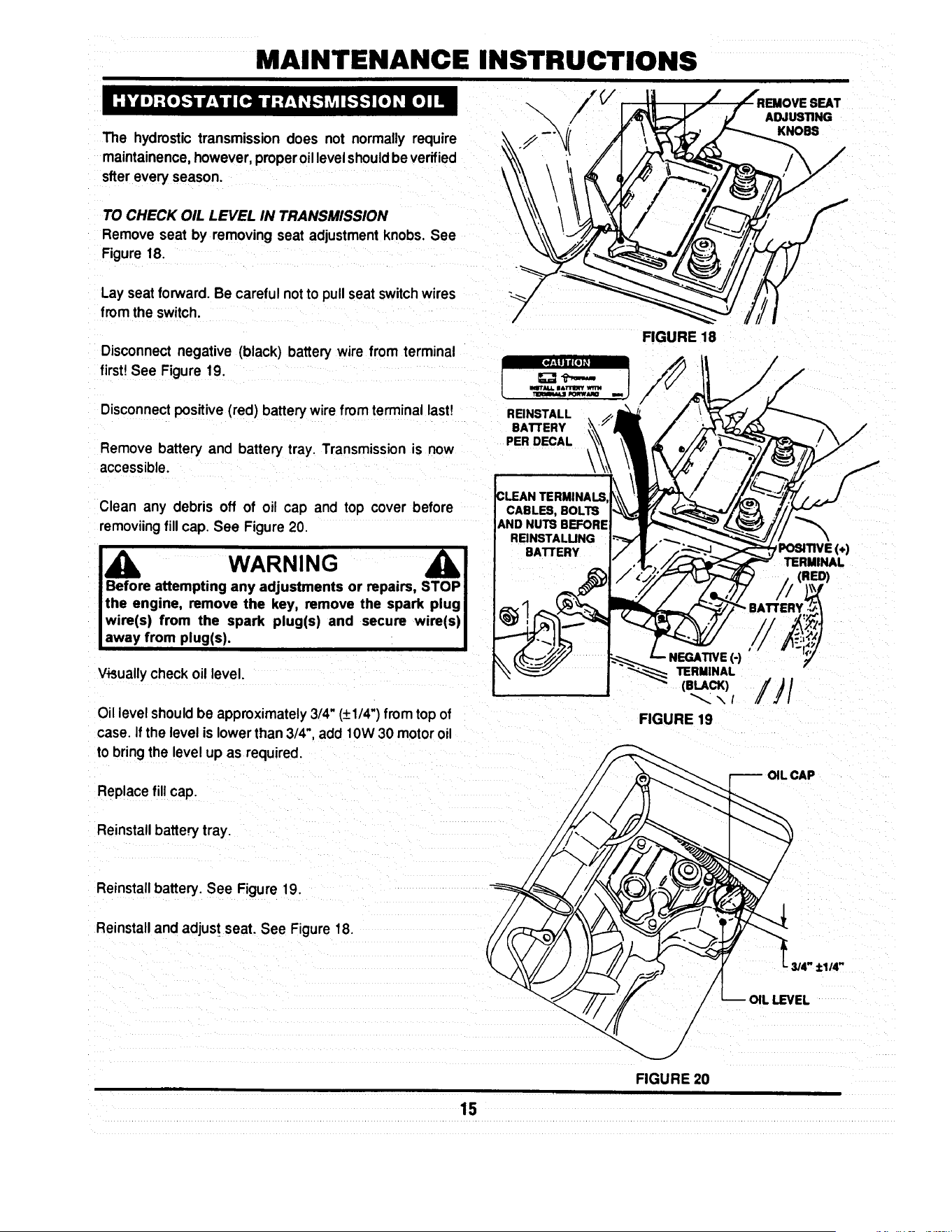
The hydrostictransmission does not normally require
maintainence,however,properoillevelshouldbeverified
sfter everyseason.
TO CHECK OIL LEVEL IN TRANSMISSION
Remove seat by removing seat adjustment knobs, See
Figure 18.
Lay seat forward. Be careful notto pullseatswitchwires
from the switch.
Disconnectnegative (black) battery wire from terminal
first!See Figure 19.
Disconnectpositive(red) battery wire from terminal last!
Remove batteryand battery tray. Transmissionis now
accessible.
\
REINSTALL
BATTERY
PER DECAL
\
FIGURE 18
SEAT
ADJUSTING
KNOBS
Clean any debris off of oil cap and top cover before
removiing fill cap. See Figure 20.
Before attempting any adjustments or repairs, STOP
the engine, remove the key, remove the spark plug
wire(s) from the spark plug(s) and secure wire(s)
away from plug(s).
Visuallycheck oil level.
Oillevelshouldbe approximately3/4" (+1/4")from topof
case. Ifthe level is lowerthan 3/4",add 10W30 motoroil
to bringthe levelup as required.
Replacefillcap.
Reinstallbattery tray.
NEGATIVE (-)
TERMINAL
(BLACK)
FIGURE 19
POSITIVE(÷)
TERMINAL
(RED)
Reinstall battery. See Figure 19.
Reinstalland adjust seat. See Figure18.
- 3/4" +1/4"
FIGURE 20
15

MAINTENANCE INSTRUCTIONS
MODELS L T120G30DB, NL T120G30DB,
LT125G33DB & LT125G38DB
These models are equipped with 12 & 12 1/2 hp engines
which are furnishes with extended oil drains. See Figure
21.
Raisetractorhood and tilt itforward.
Disconnectsparkplugwire. Securewire awayfrom soark
plug.
Put a brick or block of wood under deck wheel on opposite
side of oil drain.
Loosenoilfill cap on engine.
Placea 2 quart capacityflat containerbeneath end of oil
drain.
Removeoil plug.
Allowengineoilto drain completely.
After alloilhas drained, replace oilplugand fill enginewith
new motor oil as specifiedin Engine Owner's Manual.
MODELS LT140H33DBV, LT145H38DBV &
NL T145H38DB V
These models are equipped with 14 & 14 1/2 hp
engineswhichare furnished withFastexTM oildrains.See
Figure22.
Rotate drain body counterclockwise and pull out to open
drain.
Drainoil into a 2 quart container placed beneath end of oil
drain.
After all oil has drained, push drain body "IN" and rotate
clockwiseto close. Push drain cover over drain nipple.
Fill engine with new motor oil as specified in Engine
Owner's Manual.
NOTE:
Ifthetractor's engine is equipped withan oil filter, change
at everyoil change.Contactengine manufacturerdealer
for replacementfilter for particularengine.
ROTATE
CLOCKWISE AND
PULL OUT TO OPEN
16
FILLER
TUBE
OIL DRAIN
EXTENSION
\
FIGURE 21
FIGURE 22
PLUG
TO DRAIN OIL
L FILLER
TUBE
/
FASTEX'_
OIL DRAIN
MAINTENANCE INSTRUCTIONS
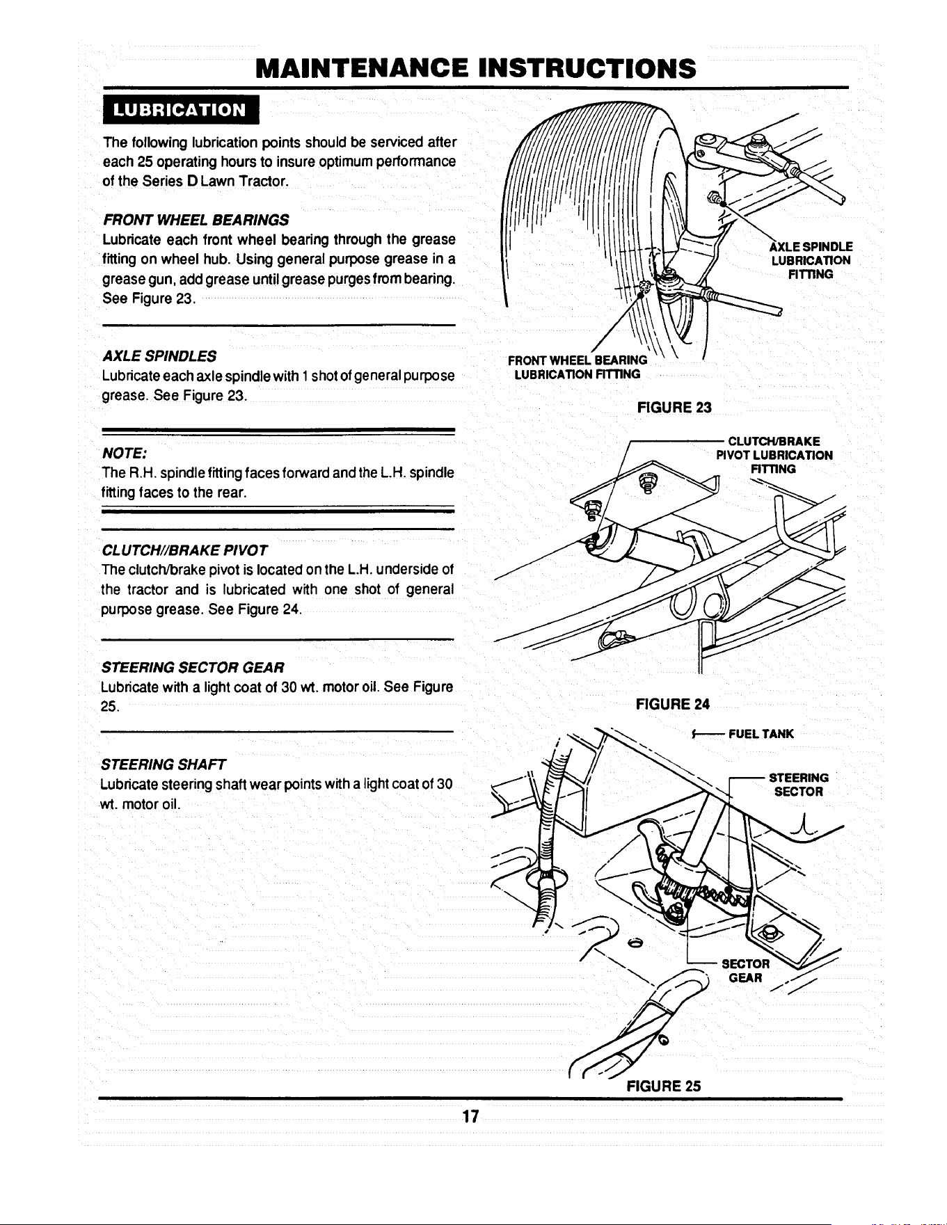
The followinglubricationpoints shouldbe servicedafter
each 25 operating hours to insure optimum performance
of the Series D Lawn Tractor.
FRONT WHEEL BEARINGS
Lubricateeach front wheel bearing through the grease
fitting on wheel hub. Using general purposegrease in a
greasegun, addgrease untilgreasepurgesfrom bearing.
See Figure 23.
AXLE SPINDLE
LUB RICATION
FITTING
AXLE SPINDLES
Lubricateeach axlespindlewith 1 shot ofgeneral purpose
grease. See Figure 23.
NOTE:
The R.H. spindle fitting faces forward and the L,H. spindle
fitting faces to the rear.
FRONT WHEEL BEARING
LUBRICATION FITTING
FIGURE 23
CLUTCH/BRAKE
PIVOT LUBRICATION
RTTING
CLUTCH//BRAKE PIVOT
The clutch/brake pivot is located on the L.H. underside of
the tractor and is lubricated with one shot of general
purpose grease. See Figure 24.
STEERING SECTOR GEAR
Lubricatewith a lightcoat of 30 wt. motoroil.See Figure
25.
STEERING SHAFT
Lubricatesteeringshaft wear pointswitha light coatof 30
wt. motoroil.
FIGURE 24
FUEL TANK
STEERING
SECTOR
SECTOR
GEAR
j"
17
FIGURE 25

MAINTENANCE INSTRUCTIONS
STEERING DRAG LINK
Lubricateboth ends of steering drag link with a small
amountof 30 wt. motoroilfrom anoilcan. See Figure26.
STEERING TIE ROD
Usingan oil can,filledwith30wt. motoroil, lubricateboth
endsof steeringtie rod. See Figure27.
BLADE ENGAGEMENT MECHANISM
Using30 wt. motor oil, lubricatethe blade engagement
mechanismpivot points,which are locatedon the R.H.
undersideof tractor.See Figure28.
PARK BRAKE LATCH
Using 30 wt. motor oil, lubricatethe park brake latch
mechanismpivot points, which are located on the L.H
undersideof tractor.See Figure29.
DECK LIFT MECHANISM
Lubricateallwear and pivotpoints ofthe deck liftmecha-
nismwith a thincoat of 30 wt. motor oil.
DRAG UNK
LUBRICATION
FIGURE 26
::::C'o:
FIGURE 27
LUBRICATE
COMPONENTS ON
UNDERSIDE
OF TRACTOR
".BLADE ENGAGEMENT
\
LEVER
FIGURE 28
PARK BRAKE
LATCH
LUBRICATE
COMPONENTS ON
UNDERSIDE
OF TRACTOR._
FIGURE 29
18
MAINTENANCE INSTRUCTIONS
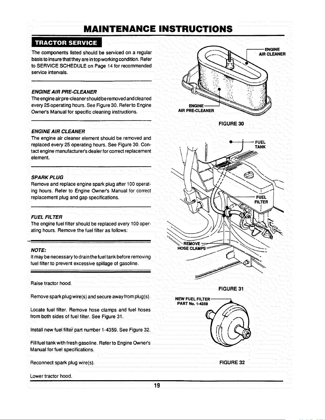
The componentslistedshouldbe servicedon a regular
basisto insurethattheyare intopworkingcondition.Refer
to SERVICE SCHEDULE on Page 14 for recommended
serviceintervals.
AIR CLEANER
ENGINE AIR PRE-CLEANER
Theengineairpre-cleanershouldbe removedandcleaned
every25 operatinghours.See Figure30. Referto Engine
Owner'sManual for specificcleaninginstructions.
ENGINE AIR CLEANER
The engine air cleaner element shouldbe removedand
replacedevery 25 operatinghours.See Figure30. Con-
tactenginemanufacturer'sdealerfor correctreplacement
element.
ENGINE
AIR PRE.CLEANER
\
\
FIGURE 30
FUEL
TANK
SPARK PLUG
Removeand replaceenginesparkplugafter 100 operat-
ing hours. Refer to EngineOwner's Manual for correct
replacementplugand gap specifications.
FUEL FILTER
Theenginefuelfiltershouldbe replaced every100 oper-
atinghours.Remove the fuel filter as follows:
NOTE:
Itmay be necessary to drainthe fuel tank before removing
fuel filter to preventexcessivespillageof gasoline.
HOSE CLAMR
Raisetractorhood.
Removesparkplugwire(s)andsecureawayfrom plug(s).
Locate fuel filter. Remove hose clamps and fuel hoses
from bothsides of fuel filter. See Figure31.
NEW FUEL FII
PART No. 1-4359
FIGURE 31
Installnew fuel filtei"part number1°4359. See Figure32,
Fillfueltankwith freshgasoline.Refer to EngineOwner's
Manualforfuel specifications.
Reconnectsparkplugwire(s).
FIGURE 32
Lowertractor hood.
19

MAINTENANCE INSTRUCTIONS
ENGINE COOLING SYSTEM
The engine coolingsystemconsists of an engineshroud
and engine fins.These shouldbe kept clean and free of
debrisas needed or clean at least every 100 operating
houm.
The batteryshouldbe servicedevery25 hours of opera-
tion.
Raiseoperator'sseat.
Removethe two adjustingknobs.
Remove seat assemblyand moveforward.Use care not
to disconnectwiresfrom seat switch.See Figure33.
Removenegative(-) cable first.
Removepositive(+) cable.
REMOVE ADJUSTING
KNOBS AND MOVE _ / --
S ,TFO.WA.0, I / ,7
f
FIGURE 33
CHECKING BATTERY ELECTROLYTE
Carefully remove battery cell covers.
Visually check electrolyte level in each cell. Level shouldbe
1/8" to 3/8" above cell plates up to the fill rings.
ELECTROLYTE
3116" ABOVE
CELL PLATES
FIGURE 34
2O
MAINTENANCE INSTRUCTIONS
Usingdistilledwater, fill cells as needed to 1/8" to 3/8"
above cell plates.
Replace cell covers.
Charge battery if required.
Install positive(+) cable first.
Install negative(-) cable last.
Install seat assembly over battery and secure in position
with adjusting knobs. Leave knobs loose.
Lower operator's seat and adjust to desired position.
Raise seat and tighten adjusting knobs.
BATTERY CHARGING
The engine is equipped with a flywheel alternator to
charge the battery. If the tractor is not run regularly,
connect the battery to a charger monthlyto maintainthe
specific gravity at 1.250 or higher. If this reading falls
below 1.175, the batteryliquidmay freeze whentempera-
turesdropto around zero degrees F. To charge, connect
perinstructionsfumishedwithcharger,If time allows, slow
charge at 1 amp for ten hours, or as an alternate, fast
charge at 3 amps forfour hours. Observe all precautions
while charging.
.LEY
TRACTION DR! VE-BEL T
Check the tractiondrivebeltfordamage andwear after25
operatinghours. The traction drive belt is locatedon the
undersideofthe tractorandspansfromthe enginepulley's
top groove to the transmissionpulley. See Figure 35.
TRACTION --
DRIVE BELT
FIGURE 35
21
MAINTENANCE INSTRUCTIONS
Should the tractiondrive belt show signs of excessive
wear or damage, replace.
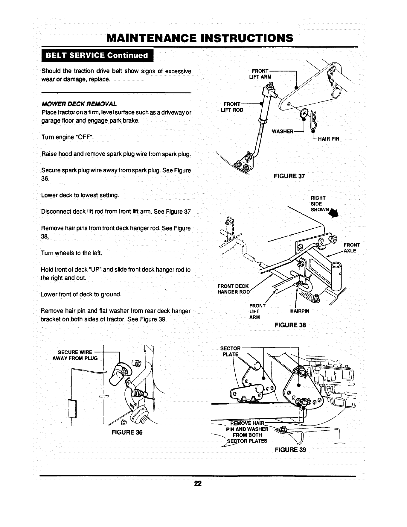
MOWER DECK REMOVAL
Placetractoron a firm,levelsurfacesuchasadrivewayor
garage floor and engage park brake.
Turnengine "OFF".
Raise hoodand removesparkplugwirefromsparkplug.
Securesparkplugwireawayfromsparkplug.See Figure
36.
\
UFT ROD
FRONT
UFT ARM
FIGURE 37
HAIR PIN
Lowerdeck to lowestsetting.
Disconnectdeck liftrodfromfrontliftarm. See Figure37
Removehair pinsfromfrontdeckhangerrod.See Figure
38.
RIGHT
SIDE
LO;T
Turnwheelsto the left, k'-,
Hold front of deck"UP"andslidefrontdeckhangerrodto ""'_%_- "'_
the right and out. FRONT DECK /"f_ _.._/_/_
HANOERROO/
Lowerfront of deck to ground. /
FRONT
Remove hair pin and flat washerfrom reardeck hanger LIFT HAIRPIN
bracket on bothsidesof tractor.See Figure39. ARM
FIGURE 38
SECURE WIRE
AWAYFROMPLUG ! t_
I
S
FIGURE 38
__.//_ SECTOR I
PIN AND WASHER_ _. ,
FROM BOTH _ /
../_.._.TO R PLATES "_' _.__L_
FIGURE 39
22

MAINTENANCE INSTRUCTIONS
Make note of hole used in sector plate.
Slide sectorplates off of rear deck hanger brackets.
Slide deck forward.
Remove deck drive beItfrom engine pulley bottom groove.
See Figure 40.
Slidedeck back and disconnect springfrom tension idler.
Pull deck from under tractor from R.H. side.
TRACTION DRIVE BELT REMOVAL
Remove two belt guide mounting bolts from each side of
tractor frame. See Figure 41.
Slide belt guide assembly to the rear and remove.
Disconnect traction belt idler pulley spring from tractor
frame. See Figure 42.
Loosen mounting nuts on traction drive belt tension and
stationary idlers just enough to allow belt to clear belt
guides. See Figure 43.
(30" & 33" BELT GUIDES SHOWN)
FIGURE 40
FIGURE 41
RIGHT REAR
TRACTOR FRAME
FIGURE 42
_I'ATIONARY------1 I-_1 _ LOO6EN
II I
IDLER
FIGURE 43
23

MAINTENANCE INSTRUCTIONS
Removetractiondrivebeltfromenginepulleytop groove.
See Figure44.
Removebelt from centerbeltguide.
Pullbelt untilitcan be removedfrom transmissionpulley.
TRACTION DRIVE BELT REPLACEMENT
Place new traction drive belt over transmission pulley and
span to engine pulley.
Place belt intotop grooveof enginepulley.
REMOVE
FROM PULLEY
Route belt through stationary and tension idlers. See
Figure45.
FIGURE 44
PULLEY
NOTE:
When installing new belt, make certain the stationary idler
is mounted in the hole closest to the L.H. side of the tractor.
See Figure 45. (See Page 29 for Belt Adjustment)
Make certainbelt is withinbeltguidesof idlers.
Attachtensionidlerspringtotractorframe. See Figure46,
Reinstall mower deck in reverse order of removal.
TENSION
IDLER
STATIONARY
IDLER
STATIONARY
IDLER
BRACKET
DE
I
RIGHT REAR
TRACTOR FRAME
STATIONARY
IDLER
FIGURE 45
\
\
!CTSPRING
TO FRAME
FIGURE 46
24

MAINTENANCE INSTRUCTIONS
30" & 33" DECK DRIVE BELT REMOVAL AND
REPLACEMENT
Inspect deck drive belt for excessive wear and damage
after every 25 operating hours. Replacement procedures
are as follows:
SPINDLE PULLEY
COVER
REMOVE
IDLER
Place tractoron a firm, level surface.
Turn engine "OFF".
Raise hood, remove spark plug wire from spark plug and
secure wire away from spark plug.
Remove mower deck.
Remove deck belt idler pulley. See Figure 47.
Remove spindle pulley cover. See Figure 47.
Remove old belt.
Replace with new belt, part number 2-2786 (30"), 2-6546
(33"), in reverse order.
/
/
FIGURE 47
SPINDLE----]
PULLEYFq L
IDLERPULLEY
FIGURE 48
Adjustidler pulley belt guide if necessary to obtain 1/16"
clearance between belt and belt guide. See Figure 48.
REMOVE IDLER ---_
38" DECK DRIVE BEL T REMOVAL/REPLACEMENT
Movetractorto a firm, levelsurface.
Turn engine "OFF".
Raise hood, remove spark plug wire from spark plug and
secure wnreaway from spark plug.
Remove deck from tractor.
Remove spindle belt guard. See Figure 49.
Remove tension idler. See Figure 49.
FIGURE 49
BELT GUARD
Remove old belt. _ ,__ . _ TENSION
p' 1,1,c,E, .cE\
Replace new belt, part number 3-5500, in reverse order. I.,_ (TYP'cAL) k_y(F_-'_o_
See Fngure 50 _pupl_ _ __._
FIGURE 50
25

MAINTENANCE INSTRUCTIONS
" W.ARNING " A I
Blades are extremely sharp and can cause severe I
injury. Wear heavy leather gloves when handling or I
working around blades. DO NOT use a blade that is I
excessively worn or damaged. I
_Ib WARNING --_
I Never use a cutting blade that shows signs oq
excessive wear or damage. Refer to Figure 4.5. Wear I
heavy leather gloves when handling or working I
around cutting blades. Blades are extremely sharPl
and can cause severe injury. I
STANDARD BLADE WEAR LIMITS
All mowerblades shouldbe checked for excessivewear
anddamage before each use.See Figure52.
30" &33"MOWER BLADEREMOVAL/REPLACEMENT
Movetractorto a firm, levelsurface.
Turn engine "OFF".
-_ -_ _ B- WEARUMIT
__ CUTTINGEDGE
-_.._ WORN
_--- C- DANGEROUSCONDITIONI
DO NOT USEON MOWERI
FIGURE 52
I11
Raise hood, remove spark plug wire from spark plug and r-_ NUT BLADE-JJ-_ ./1
secure wire away from spark plug. 1 _-FF-'-LOCK WASHER I/I _ I
e ove eo ,ro traOor.
Install new 30" blade, pad number 1-8069, or 3-4168 for _J/ "_/
33" blade mounting bar. v__
BLADEMOUNTINGBOLTS
FIGURE 53
28
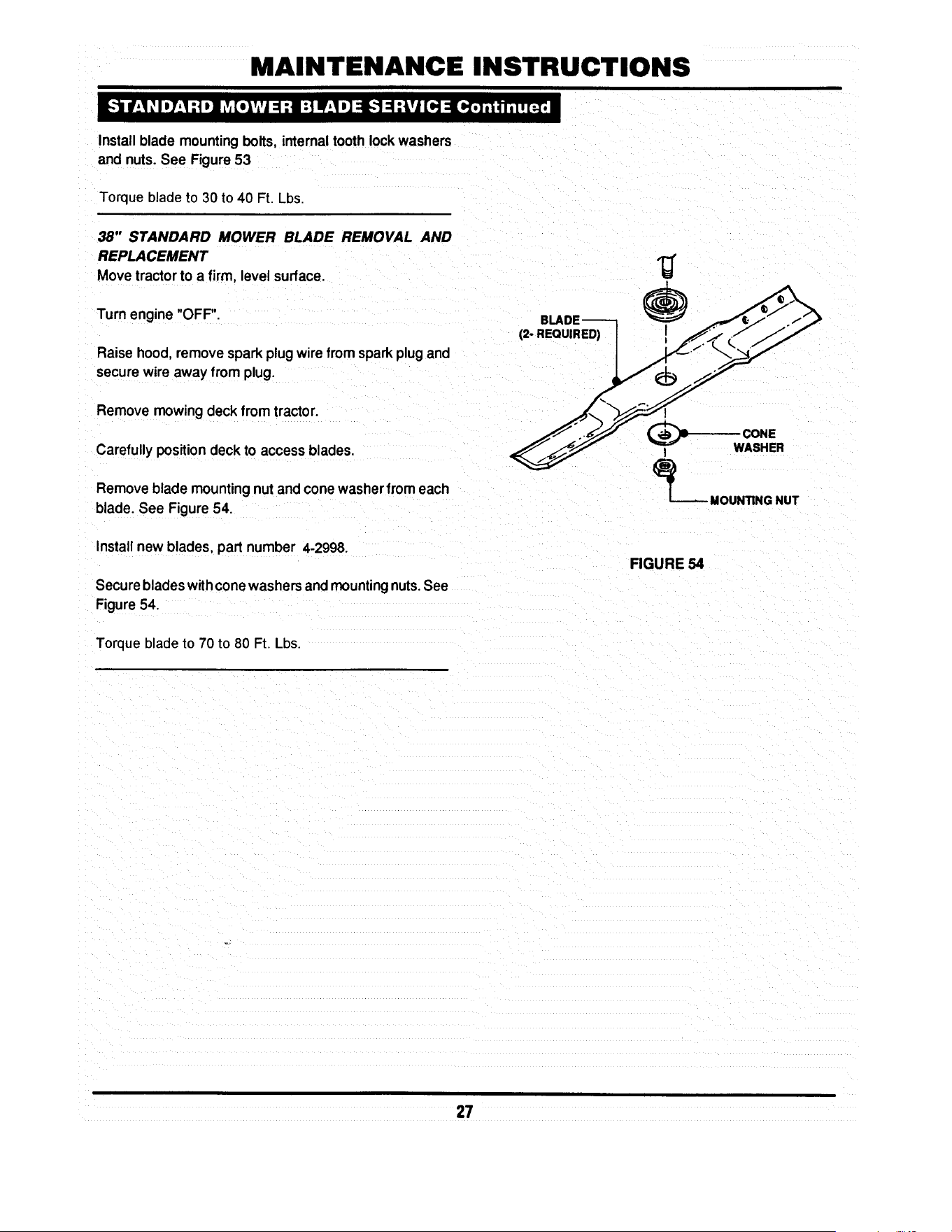
MAINTENANCE INSTRUCTIONS
Install blade mounting bolts, internal tooth lock washers
and nuts. See Figure 53
Torque blade to 30 to 40 Ft, Lbs.
38" STANDARD MOWER BLADE REMOVAL AND
REPLACEMENT
Move tractor to a firm, level surface.
Turn engine "OFF".
Raise hood, remove spark plug wire from spark plug and
secure wire away from plug.
Remove mowing deck from tractor.
Carefully position deck to access blades.
Remove blade mounting nut and cone washer from each
blade. See Figure 54.
Install new blades, part number 4-2998.
Secure blades with cone washers and mounting nuts. See
Figure 54.
Torque blade to 70 to 80 Ft Lbs.
(2- REQUIRED)
CONE
I WASHER
_ MOUNTING NUT
FIGURE 54
27

MAINTENANCE INSTRUCTIONS
SHARPENING STANDARD BLADE(S)
Blades should be kept sharp at all times. When the
blade(s) are dull, cut grass will be ragged and lawn will
usuallyturn brown.Sharpen standardbladesas follows:
Movetractorto a firm, levelsurface.
Tum engine "OFF'.
Raise hood,removesparkplugwirefromsparkplugand
securewire away from plug.
Remove mowing deck fromtractor.
Remove mower blade(s)
Inspectfor excessivewear or damage.
FIGURE 56
Never use a blade that shows signs of
exceaslve wear or damage. Refer to Figure
52 for standard blade wear limits.
Sharpenstandardmowerblade(s) at 25° angle+3°. See
Figure 56.
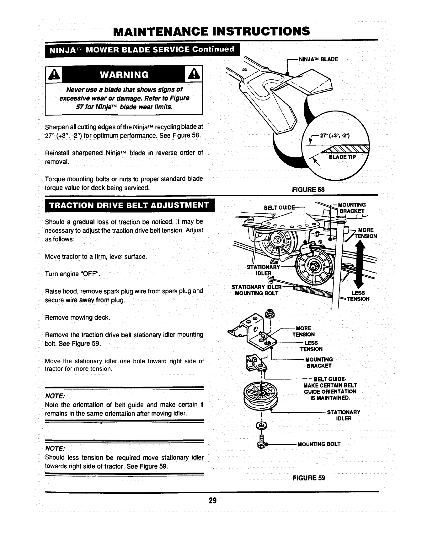
NINJATM BLADE WEAR LIMITS
The NinjaTM recyclingblade requiresmorefrequentser-
vice intervalsthan standardblades. Check the NinjaTM
recyclingblade for excessivewear or damageafterevery
use. See Figure 57.
NINJATM BLADE SHARPENING
The NinjaTM recycling blade requires more frequent
sharpening than standard blades due to its recycling
method.
Remove the NinjaTM blade by followingproceduresfor
standardblade removal.
Inspectthe NinjaTM bladefor excessivewear or damage.
See Figure57 for NinjaTM bladewear limits,
B- WEAR UMIT
(CRACKS OR NOTCHES
BEGIN TO APPEAR)
_ DANGEROUS CONDITIONI / _2._ ._,' 'It
DO NOT USE ON MOWERI "_ "_ _
FIGURE 57
28
MAINTENANCE INSTRUCTIONS
Never use a blade that shows signs of
excessive wear or damage. Refer to Figure
57 for NinJaTM blade wear limits.
Sharpen allcuttingedges ofthe NinjaTM recycling blade at
27° (+3°, -2 °) for optimum performance. See Figure 58.
Reinstall sharpened NinjaTM blade in reverse order of
removal.
Torque mounting bolts or nuts to proper standard blade
torque value for deck being serviced.
BLADE
FIGURE 58
Should a gradual loss of traction be noticed, it may be
necessary to adjust the traction drive belt tension. Adjust
as follows:
BELT
BRACKET
MORE
Movetractor to a firm, level surface.
Turn engine "OFF".
Raise hood remove spark plug wire from spark plug and
secure wire away from plug.
Remove mowing deck.
Remove the traction drive belt stationary idler mounting
bolt. See Figure 59.
Move the stationary idler one hole toward right side of
tractor for more tension.
NOTE:
Note the orientation of belt guide and make certain it
remainsin the same orientationafter moving idler.
NOTE:
Should less tension be required move stationaryidler
towardsright side of tractor. See Figure59.
|
IDLER
STATIONARY
MOUNTING BOLT
LESS
BELT GUIDE-
MAKE CERTAIN BELT
GUIDE ORIENTATION
IS MAINTAINED.
I
÷
STATIONARY
IDLER
MOUNTING BOLT
FIGURE 59
29

MAINTENANCE INSTRUCTIONS
Securestationaryidlerwith mountingbolt.
Place sparkplug wire onto spark plug.
Setpark brake.
Start Engine.
Visuallyinspecttractiondrive beltfor movement.
When properlyadjusted,the tractiondrivebelt shouldnot
have any movement or rotationwith the engine running
and park brake engaged.
Shouldmovement be present,readjusttractiondrive belt
to releasebeittension asdescribedinpreviousinstructions.
Movetractorto a firm, levelsurface. /
Turn engine"OFF'.
Raisehood,remove sparkplug wirefrom sparkplug and
securewire away fromplug.
Movebladeengagement leverdownto"OFF".See Figure ._._:
60. -::
E
ENGAGEMENT
TO "OFF"
Lower deckto lowest cutting position
Checkfrontto rear level.
If deck front to rear level is not correct,
thiscouldcause blade beltproblems.
30" & 33" DECKS
Measure length of blade cable extensionspring. See
Figure61.
Moveblade engagement lever to "ON".
Measure blade cable extension spring.Spring should
extend1"+_1/8"for properbelttension.See Figure61.
EXTENSION SPRING
FIGURE 60
FIGURE 61
3O
MAINTENANCE INSTRUCTIONS
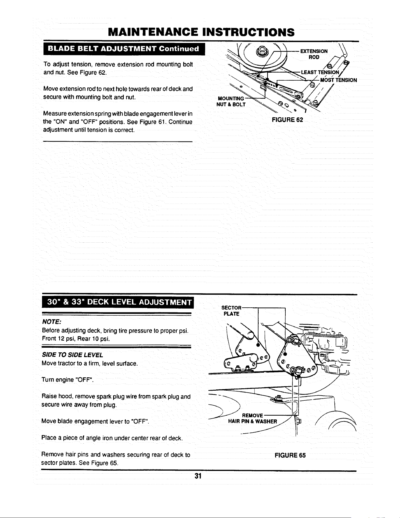
To adjust tension, remove extension rod mountingbolt
and nut. See Figure62.
Move extension rodto next hole towards rear of deck and
securewith mountingbolt and nut. MOUNTING-
NUT & BOLT
Measure extension spring with blade engagement lever in
the "ON" and "OFF" positions. See Figure 61. Continue
adjustment until tension is correct.
I
-_LEAST TENSION/d
• _L / MOSTTENSlON
"-_ //
FIGURE 62
NOTE:
Before adjusting deck, bring tire pressureto properpsi.
Front12 psi, Rear 10 psi.
SIDE TO SIDE LEVEL
Movetractorto a firm, level surface.
Turn engine "OFF".
Raisehood, remove spark plugwire from spark plug and
securewire away from plug.
Move blade engagement lever to "OFF".
Place a piece of angle iron under center rear of deck.
SECTOR
PLATE
__ REMOV_ _
Remove hair pins and washers securing rear of deck to
sector plates. See Figure 65.
FIGURE 65
31
MAINTENANCE INSTRUCTIONS
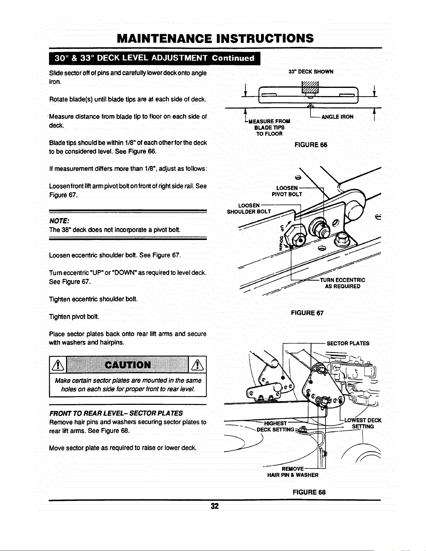
Slidesectoroffof pinsandcarefullylowerdeckontoangle
iron.
33" DECK SHOWN
Rotate.blade(s) untilblade tipsare at each sideof deck.
•Measuredistancefrom blade tipto flooron each sideof LMEASUREFROM
deck. BLADE TIPS
TO FLOOR
Bladetips shouldbe within1/8"ofeach otherfor thedeck
to be consideredlevel. See Figure66.
If measurementdiffersmore than 1/8",adjustas follows:
Loosenfrontliftarm pivotboltonfrontof rightsiderail.See
Figure67.
NOTE:
The 38" deck does not incorporatea pivotbolt.
PIVOT BOLT
LOOSEN
SHOULDER BOLT
_-_ ANGLE IRON
FIGURE 66
f
Looseneccentricshoulderbolt. See Figure67.
Turneccentric"UP"or'DOWN" as requiredto leveldeck.
See Figure67.
Tighteneccentricshoulderbolt.
Tighten pivotbolt.
J
ECCENTRIC
AS REQUIRED
FIGURE 67
Place sector plates back onto rear lift arms and secure
withwashersand hairpins. SECTORPLATES
Make certainsector plates are mountedin the same _---_,,, ,,__ _;¢__ ________
holeson each side forproper frontto rearlevel.
FRONT TO REAR LEVEL-SECTOR PLATES --_-- "_-_
LOWEST OE
Removehairpinsand washerssecuringsectorplatesto
rearliftarms.See Figure 68. _ ~ _DECI(-S'_ING _ -------_-SETTING
Movesectorplate as requiredto raiseorlowerdeck. ___.-__ .)_1--'_ I_11_1_
DECK
REMOVE'
HAIR PIN & WASHER
FIGURE 68
32

MAINTENANCE INSTRUCTIONS
NOTE:
Thedeck shouldbe set sothat the rearofthe deck is 1/4"
lowerthan the front.See Figure69.
FRONT
X • 1/4"
33" DECK SHOWN
P'/////;! REAR
FRONT TO REAR LEVEL- FRONT LIFT ROD
If the sector plates are in their lowest setting and proper L__ MEASUREFROM
level cannot be obtained, adjust the front liftrod as follows: BLADETIPSTOFLOOR
x
f
FIGURE 69
Movedeck lift leverto #5 position.
30" & 33" DECK
Place a 2X4 woodenblockon edge underfrontcenter of
deck.
Place a 3X3 wooden blockunder rearcenter of deck.
NUT
/
/
Remove hair pins and washers securingsectorplates.
Lowerrear of deck onto3X3 block. See Figure68.
Removehairpinand washer securingfrontliftrodtofront
liftarm. See Figure 70.
Removefront lift rod andcarefullyrestfrontof deckonto
2X4 block.
Loosenjam nuton front liftrod.See Figure70.
•HAIR PIN
_ FRONT UFT ROD
FIGURE 70
Turnfrontliftrodhangerblockuntilitcan be reinstalledinto
frontlift arm withoutliftingdeck. See Figure70.
Secure lift rodto liftarm withwasher and hair pin.
Placesector platesonto rearhanger bracketsandsecure
withwashers and hair pins.
Raisedeck and remove wooden blocks.
Repeat steps for frontto rear level adjustment.Referto
FRONT TO REAR LEVEL- SECTOR PLATESo
Make certainsector plates are mountedin the same I
holes on each sidefor proper front to rear level. I
33
MAINTENANCE INSTRUCTIONS
NOTE:
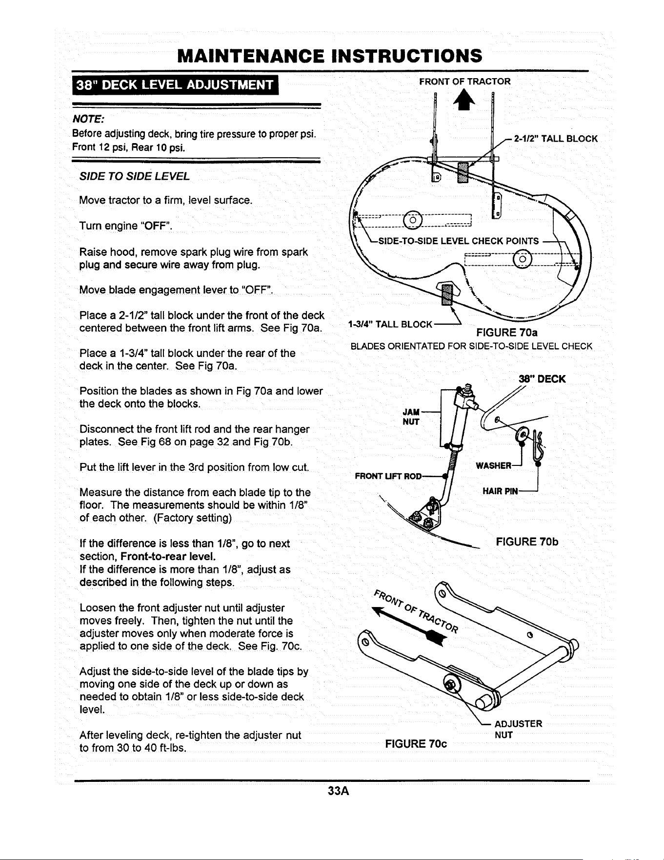
Before adjusting deck, bring tire pressureto proper psi.
Front 12 psi, Rear 10 psi.
SIDE TO SIDE LEVEL
FRONT OF TRACTOR
BLOCK
Move tractor to a firm, level surface.
Turn engine "OFF".
Raise hood, remove spark plug wire from spark
plug and secure wire away from plug.
Move blade engagement lever to "OFF".
Place a 2-112" tall block under the front of the deck
centered between the front lift arms. See Fig 70a.
Place a 1-3/4" tall block under the rear of the
deck in the center. See Fig 70a.
Position the blades as shown in Fig 70a and lower
the deck onto the blocks.
1-3/4"TALLBLOCK_--_
FIGURE 70a
BLADESORIENTATEDFORSIDE-TO-SIDELEVELCHECK
38" DECK
Disconnect the front lift rod and the rear hanger
plates. See Fig 68 on page 32 and Fig 70b.
NUT
Put the lift lever in the 3rd position from low cut.
Measure the distance from each blade tip to the
floor. The measurements should be within 1/8"
of each other. (Factory setting)
If the difference is less than 1/8", go to next
section, Front-to-rear level.
If the difference is more than 1/8", adjust as
described in the following steps.
FRONT UFT
FIGURE 70b
Loosen the front adjuster nut until adjuster
moves freely. Then, tighten the nut until the
adjuster moves only when moderate force is
applied to one side of the deck. See Fig. 70c.
Adjust the side-to-side level of the blade tips by
moving one side of the deck up or down as
needed to obtain 118" or less side-to-side deck
level.
After leveling deck, re-tighten the adjuster nut
to from 30 to 40 ft-lbs.
FIGURE 70c
\
_ADJUSTER
NUT
33A

MAINTENANCE INSTRUCTIONS
Attach the rear hanger plates to the hole that
most closely aligns with the pin on the deck lift
bracket. Secure with washer and hair pin.
/h[ i !! !!ii! iiiii!i i ii! !i!!!i! !i Iiiiic i! !i ! Ni i ii!i Mii iii iii ii i i i i i i iiiiiiiiiiiiiii!j/hi
Make certain sectorplatesare mountedin the same I
holes on each side for proper frontto rear level J
FRONT OF TRACTOR
Adjust the swivel on the front lift rod until it
lines up with the hole in the front lift bracket.
(make sure the lift rod is at the top of the slot in
the deck bracket) Secure with hair pin.
FRONT TO REAR LEVEL
Position the blades as shown in Fig. 70d.
Measure the distance from the left front blade
tip to the ground and from the right rear blade
tip to the ground. The front left blade tip should
be between 1/8" and 3/8" higher than the right
rear (factory setting). If it is between 1/8" and
3/8" you are finished with adjustment.
If it is not within specifications, adjust by raising
or lowering the front of the deck using the
the swivel on the front lift rod. Turning the swivel
clockwise will raise the front of the deck. Turning
the swivel counter-clockwise will lower the front of
the deck.
BLADE TIP
\
\
RIGHT REAR BLADE TIP
FIGURE 70d
BLADESORIENTATEDFORFRONT-TO-REAR
LEVELCHECK
NOTE:
The deck should be set sothat the rear of the deck is 1/4"
lowerthan the front. See Fig. 70e.
33" DECK SHOWN
FRONT
JL MEASURE FROM
BLADE TIPS TO FLOOR
REAR
FIGURE 70e
X
f
33B

MAINTENANCE INSTRUCTIONS
STEERING SECTOR
Should excessive "PLAY" be present in the steering,
adjustas follows:
Tum Engine"OFF" and raise tractorhood.
Removespark plugwire from spark plug and securewire
away from plug.
From leftside of tractor,locatethe steeringsectorbelow
fuel tank. See Figure 71.
Looseneccentricmounting nut.
Rotate eccentric clockwise until steering "PLAY" is re-
duced.See Figure 71.
Tighteneccentricmounting nut.
Replacespark plugwire onto sparkplugand lowerhood.
FIGURE 71
If movement of tractor does not correspond with the
selectedspeedonshiftquadrant,adjustthe speedcontrol
lever as follows:
Withengine running,drivetractor and move shiftleverto
locateneutral.
Turn engine "OFF".
Raise hood,remove sparkplugwire fromsparkplugand
securewire away from plug.
Locate speed control lever mount behind right rear tire.
See Figure72.
Loosenmountingnuts.
Movethe speed controlleveruntilit is indirectrelationto
the neutral"N"position on quadrant. See Figure 73.
Tighten mounting nuts.
SPEED CONTROL
LEVER MOUNT
ED
CONTROL
LEVER
®
MOUNTING (_
NUTS
FIGURE 72
SPEED CONTROL LEVER
MOVE TO NEUTRAL
(N) POSITION
FIGURE 73
34

MAINTENANCE INSTRUCTIONS
HYDRO DRIVE MODELS
To be properlyadjusted,the brake shouldstopthe tractor
inapproximately6 feet from top speed when the clutch/
brake pedal is fully depressed.
Adjustbrake when necessary as follows:
Turnengine "OFF'.
Raise hood, remove spark plugwire fromsparkplugand
securewire away from plug.
Locatebrake adjustmenton rightsideoftractor infrontof
andbehind rightrear wheel. See Figure74.
Turn nut clockwise to increase braking action or, coun-
terclockwiseto decrease brakingaction.See Figure 74.
Replace spark plugwire, startengine andtest brake.
Continue adjustment as described above until proper
adjustmentis achieved.
GEAR DRIVE MODELS
Tobe properlyadjusted,the brakeshouldstopthe tractor
inapproximately6 feet fromtop speed when the clutch/
brakepedal is fully depressed.
Adjustbrake when necessaryas follows:
Turn engine "OFF".
Raisehood, remove sparkplugwire from spark plug and
securewire away from plug.
Locatebrake adjustmenton rightsideof tractorin backof
and behind rightrear wheel. See Figure 75.
Turn nut clockwise to increase braking action or, coun-
terclockwiseto decrease brakingaction.See Figure75.
Replace spark plugwire, startengine and test brake.
Continue adjustment as described above until proper
adjustmentis achieved.
\
FIGURE 74
ADJUSTMENT
FIGURE 75
BRAKE
35

ELECTRICAL
Figure 76 illustratestypical hamess mutingon all the
Series D Lawn Tractors. Use this when locatingvarious
electricalcomponents.
_---- O BATI1ERY
NEGATIVE (-)
-TO BATTERY
PosmvF.(+)
TERMINAL
D
(UNDER SEAT)
R,H°
HEADLIGHT
SWITCH
BLADE ENGAGEMENT
LEVER SWITCH
SWITCH
20 AMP-
FUSE
BRAKE
SWITCH
HEADUGHT
HEAD
HARNESS
HARNESS
GROUND
TO ENGINE
FIGURE 76
36

ELECTRICAL
The schematics below, Figure 77 & Figure 78 represent
models with and without headlights.
BRIGGS & STRA TTON WITHOUT LIGHTS
STARTER k
"EDI
/-IGNITION
ENGINE /GROUND
RED
RED
'_--ALTERNATOR
BLACK RED
BATTERY
PEDAL SWITCH
INoj. I
I
I
BLACK
GREENI I N_ I II
I I BLACK
RED
I
B_ YELLOW
BLUE
FIGURE 77
BRIGGS & STRA TTON WITH LIGHTS
ANTI-AFTER FIRE
SOLENOID --_
\
\
ENGINE
STARTER
BLACK
BAI"rlERY
IGNmON GROUND
AC OUTPUT
RED
PINK
RED
ALTERNATOR
RED
SOLENOID
RED
PEDAL
SWITCH
BLACK
PTO
SWITCH
RED
BLACK
BLACK
UGHT
SWITCH
_mTION
KEYswrrc_
YEllOW
SEAT
SWITCH
IN_ I
I" Tl
r
HEAD
UGHTS
SEAT
SWITCH
GREEN
PURPLE
FIGURE 78
37
!
3 YEAR LIMITED WARRANTY
For three (3) years from purchase date for the original purchaser's residential, non-commercial use, SNAPPER, through
any SNAPPER dealer will replace, free of charge (except for taxes where applicable), any part.or parts found upon
examination by the factory at McDonough, Georgia, to be defective in material or workmanship or both.
For ninety (90) days from purchase date for the odginal purchaser's commercial, rental, or other non-residential use
SNAPPER, through any SNAPPER dealer will replace, free of charge, any part or parts found upon examination by th=
factory at McDonough, Georgia, to be defective in material or workmanship or both.
All transportation costs incurred by the purchaser in submitting material to a SNAPPER dealer for replacement under
this warranty must be paid by the purchaser.
This warranty does not apply to engines and their components, hydro transmissions, gear drive transmissions and
batteries, as these items are warranted separately. This warranty does not apply to parts that have been damaged by
accident, alteration, abuse, improper lubrication, normal wear, or other cause beyond the control of SNAPPER. This
warranty does not cover any machine or component part that has been altered or modified changing safety,
performance, or durability.
There is no other express warranty.
DISCLAIMER OF WARRANTY
Implied warranties, including those of merchantability and fitness for a particular purpose, are limited to three
(3) years from purchase date for the original purchaser's residential or other non-commercial use, and ninety
(90) days from purchase for the original purchaser's commercial, rental or other non-residential use, and to the
extent permitted by law, any and all implied warranties are excluded. This is the exclusive remedy. Liabilities
for consequential damages, under any and all warranties are excluded.
Some states do not allow limitations on how long an implied warranty lasts, or do not allow the exclusion or
limitation of incidental or consequential damages, so the above limitation or exclusion may not apply to you.
This warranty gives you specific legal rights, and you may also have other rights which vary from state to state.
WARNING: THE USE OF REPLACEMENT PARTS OTHER THAN GENUINE SNAPPER PARTS MAY IMPAIR THE
SAFETY OF SNAPPER PRODUCTS AND WILL VOID ANY LIABILITY AND WARRANTY BY SNAPPER
ASSOCIATED WITH THE USE OF SUCH PARTS.
IMPORTANT: Please fill outthe attachedSNAPPER Product RegistrationCard immediatelyand mail to:
Snapper's Product Registration Center, P.O. Box 777, McDonough, Georgia 30253

SERVICE NOTES

SERVICE NOTES

Safety Instructions & Operator's Manual for
8NAPPER
LAWN TRA C TOR
HYDROSTA TIC &
GEAR DRIVE
SERIES D
IA WARNING: The engine exhaust from this product contains chemicals known to the State I
of Califomia to cause cancer, birth defects or other reproductive harm.
I
COPYRIGHT © 1998
SNAPPER INC
ALL RIGHTS RESERVED
MANUAL No. 3-5576 (REV. 2, 6/98)

Safety Instructions & Operator's Manual for
,SNAPPER,
LAWN TRA CTOR
HYDROSTATIC &
GEAR DRIVE
SERIES D
MODELS
GEAR DRIVE HYDROSTATIC
DRIVE
LT120G30DB LT140H33DBV
NLT120G30DB LT145H33DBV
LT125G38DB LT145H38DBV
NLT145H38DBV
I
MODEL DESIGNATION
ENGINE HP
DRIVE SYSTEM TYPE
CUTTING WIDTH
MODEL NUMBER EXPLANATION
LT I 145I H 1381 O I B I V I
i ENGINE TYPE
; ENGINE MODEL
SERIES DESIGNATION
LT - Lawn Tractor Model Designation
120 - 12.0 HP Engine Horse Power
125 - 12,5 HP Engine Horse Power
H - Hydrostatic Transmission
30 - 30" Cutting Width Mower
33 - 33" Cuttino Width Mower
140 - 14.0 HP Engine Horse Power
145 - 14.5 HP Engine Horse Power
G - Gear Drive Transmission
38 - 38" Cutting Width Mower
D - Series Designation
B - Briggs & Stratton Engine
V - Over Head Valve Type Engine
Thank you for buying a SNAPPER product! Before operating the Lawn Tractor, read and follow the
"IMPORTANT SAFETY INSTRUCTIONS" on pages 2 & 2A, all other instructions contained in this manual and
the accompanying booklet "About Power Mower Safety". "Lawn mowers and all power equipment can be
potentially dangerous ff used improperly. REMEMBER: SAFETY REQUIRES CAREFULL USE IN ACCORDANCE
WITH INSTRUCTIONS AND COMMON SENSE/.
COPYRIGHT © 1998
SNAPPER NC
ALL RIGHTS RESERVED
MANUAL No. 3-5576 (REV. 2, 6/98)

IMPORTANT SAFETY INSTRUCTIONS
WARNING: This powerful cutting machine is capable of amputating hands and feet and can throw objects that
can cause injury and damage! Failure to comply with the following SAFETY instructions could result in
serious injury or death to the operator or other persons. The owner of the machine must understand these
instructions and must allow only persons who understand these instructions to operate machine. Each
person operating the machine must be of sound mind and body and must not be under the influence of any
substance which might impair vision, dexterity or judgment. If you have any questions pertaining to your
machine which your dealer cannot answer to your satisfaction, call or write the Customer Service Department
at SNAPPER, McDonough, Georgia 30253. Phone: (1-800-935-2967).
PROTECTION FOR CHILDREN
Tragic accidents can occur if the operator is not alert
to the presence of children. Children are often
attracted to the machine and the mowing activity.
Never assume that children will remain where you
last saw them.
1. KEEP children out of the mowing area and under
the watchful care of a responsible adult.
2. DO NOT allow children in yard when machine is
operated (even with the blade OFF).
3. DO NOT allow children or other passengers to
ride on machine or on attachments (even with the
blade OFF). They may fall and be seriously
injured.
4. DO NOT allow pre-teenage children to operate
machine.
5. ALLOW only responsible adults & teenagers with
mature judgment under close adult supervision to
operate machine.
6. BE SURE the area is clear of others before
mowing and turn machine OFF if anyone enters
the area.
7. DO NOT mow in reverse unless absolutely
necessary. LOOK BEHIND and down for small
children before and when backing.
8. USE EXTRA CARE when approaching blind
corners, shrubs, trees, or other objects that may
obscure vision.
PROTECTION AGAINST TIPOVERS
Slopes are a major factor related to loss-of-control
and tip-over accidents, which can result in severe
injury or death. All slopes require extra CAUTION. If
you cannot back up the slope or if you feel uneasy on
it, DO NOT mow it. Use extra care with grass catchers
or other attachments; these can change the stability
of the machine.
1. DO NOT operate machine on slopes exceeding 15
degrees (27% grade).
2. Exercise EXTREME CAUTION on slopes above 10
degrees (18% grade). Turn blade OFF when
traveling uphill. Use first speed and avoid sudden
or sharp turns.
3. DO NOT mow back and forth across face of
slopes. Mow up and down.
PROTECTION AGAINST TIPOVERS
(Continued From Previous Column)
4. AVOID uphill starts. If machine stops going uphill
or tires lose traction, turn blade OFF and back
slowly down the slope.
5. STAY ALERT for holes and other hidden hazards.
Tall grass can hide obstacles. Keep away from
ditches, washouts, culverts, fences and
protruding objects.
6. KEEP A SAFE DISTANCE (at least 3 feet) away
from edge of ditches and other drop offs. The
mower could turn over if an edge caves in.
7. Always begin forward motion in the #1 speed
position.
8. Use weights or a weighted load carrier in
accordance with instructions with a grass catcher
on slopes above 10 degrees (18% grade).
9. DO NOT put your foot on the ground to try to
stabilize the machine.
10. DO NOT mow on wet grass. Reduced traction
could cause sliding.
11. DO NOT mow under any condition where traction,
steering or stability is doubtful without first test
driving over the terrain with blade OFF.
PREPARATION
1. Read this manual, get to know where all controls
are located and practice how to use them before
starting for the first time, and at the beginning of
each season. Read and follow Warnings and
Instructions on engine and machine. Read and
follow operator's manual and instructions
furnished with attachments.
2. Only mature, responsible persons shall operate
the machine and only after proper instruction.
3. Handle fuel with extra care. Fuels are flammable
and vapors are explosive. Use only an approved
fuel container. Never remove fuel cap or add fuel
with engine running. Add fuel outdoors only with
engine stopped and cool. Clean spilled fuel from
machine. DO NOT smoke.
4. Practice operation of machine with BLADE OFF to
learn controls and develop skills.
(Continued on Next Page}

IMPORTANT SAFETY INSTRUCTIONS
PREPARATION
(Continued From Previous Page)
5. Check the area to be mowed and remove all
objects such as toys, wire, rocks, limbs and other
objects that could cause injury if thrown by blade
or interfere with mowing.
6. Keep people and pets a safe distance from
machine.
7. Check shields, deflectors, switches, blade
controls and other safety devices frequently for
proper operation and location.
8. Make sure all safety decals are clearly legible.
Replace if damaged.
9. Protect yourself when mowing and wear safety
glasses, long pants and substantial footwear.
10. Know how to STOP blade and engine quickly in
preparation for emergencies.
11. Use extra care when loading or unloading the
machine into a trailer or truck.
12. Check grass catcher components frequently for
signs of wear or deterioration and replace as
needed to prevent injury from thrown objects
going through weak or worn spots.
OPERATION
1. Mount and dismount machine from left side.
2. Start engine from operator's seat, if possible.
Make sure blade is OFF and parking brake is set.
3. STOP blade, STOP engine, set parking brake and
remove key when leaving machine.
4. DO NOT operate machine unless properly seated
with feet on feet rests or pedal(s).
5. STOP BLADE and ENGINE and make sure blade
has stopped before removing grass catcher or
unclogging mower to prevent loss of fingers or
hand.
6. Blade must be OFF except when cutting grass.
Set blade in highest position when mowing over
rough ground.
7. Keep hands and feet away from rotating blade
underneath deck. NEVER place foot on ground
while BLADE is ON or machine is in motion.
8. Deflector or entire grass catcher must be in place.
NEVER point discharge at people, passing cars,
windows or doors.
9, Slow down before turning.
MAINTENANCE
1. Never store machine or fuel container inside
where fumes may reach an open flame, spark or
pilot light such as in a water heater, furnace,
clothes dryer or other gas appliance. Allow
engine to cool before storing machine in an
enclosure. Store fuel container out of the reach of
children in a well ventilated, unoccupied building.
2. Keep engine free of grass, leaves or excess
grease to reduce fire hazard and engine
overheating.
3. When draining fuel tank, drain fuel into an
approved container outdoors and away from open
flame.
4. Check brakes frequently; adjust, repair or replace
as needed.
5. Keep all bolts, nuts and screws properly tight.
Check that all cotter pins are in proper position.
6. Always provide adequate ventilation when
running engine indoors. Exhaust gases contain
carbon monoxide, an odorless and deadly
poison.
7. Disconnect negative (black) cable from battery
before performing maintenance or service.
Cranking engine could cause injury.
8. Never work under machine without safety blocks.
9. Service engine and make adjustments only when
engine is stopped. Remove spark plug wire(s)
from spark plug(s) and secure wire(s) away from
spark plug(s).
10. DO NOT change engine governor speed settings
or overspeed engine.
11. Lubricate machine at intervals specified in
manual to prevent controls from binding.
12. Mower blades are sharp and can cut. Wrap the
blades or wear heavy leather gloves and use
CAUTION when handling them.
13. NEVER test for spark by grounding spark plug
next to spark plug hole; spark plug could ignite
gas exiting engine.
14. Have machine serviced by an authorized
SNAPPER dealer at least once a year and have the
dealer install any new safety devices.
15. Use only genuine SNAPPER replacement parts to
assure that original standards are maintained.
10. Watch out for traffic when near or crossing
roadways.
11. STOP engine immediately after striking an
obstruction. Inspect machine and repair damage
before resuming operation.
12. Mow only in daylight or with good artificial light.
13. Move joystick (if equipped) SLOWLY to maintain
control during speed and directional changes.
14. Exercise CAUTION when pulling loads. Limit
loads to those you can safely control and attach
loads to hitch plate as specified with SNAPPER
attachment instructions.
2A

TABLE OF CONTENTS
IMPORTANT SAFETY INSTRUCTIONS ...... 2 & 2A
TABLE OF CONTENTS ........................................ 3
FAMILIARIZATION ............................................. 4-5
Serial & Model Number Location ........................... 4
Controls .................................................................... 5
Components ........................................................... 5
OPERATING INSTRUCTIONS ........................ 6-11
Pre-start Checklist ................................................... 6
Adjusting Operator's Seat ....................................... 6
Starting & Stopping Engine ....................................... 7
Starting & Stopping Wheel Drive ............................... 8
Setting & Releasing Parking Brake ..........................
Starting & Stopping Mower Blades .......................... 9
Adjusting Cutting Height ......................................... 10
Raising Chute Deflector ......................................... 10
Rolling Tractor W_h Engine Off ......................... 9-10
Tips on Mowing ....................................................... 11
ACCESSORIES .................................................. 11
TROUBLESHOOTING GUIDE ....................... 12-13
MAINTENANCE INSTRUCTIONS ................. 14-35
Service Schedule ......................................... 14
Maintenance Parts ....................................... 14
Hydrostatic Transmission Oil .................... 15
To CheckOilLevel...............................................
Changing Engine Oil ................................... 16
Lubrication (Tractor] .............................. 17-18
Front Wheel Bearings ......................................... 17
Axle Spindles ....................................................... 17
Steering Shaft ...................................................... 17
Clutch/Brake Pivot............................................... 17
Steering Sector Gear .......................................... 17
Steering Drag Link .............................................. 18
Steering Tie Rod ................................................. 18
Park Brake Latch ................................................ 18
Deck Lift Mechanism .......................................... 18
Blade Engagement Mechanism ......................... 18
Engine Service ............................................. 19
Engine Air Pre-Cleaner ....................................... 19
Engine Air Cleaner .............................................. 19
Spark Plug ........................................................... 19
Fuel Filter ........................................................... 19
Engine Cooling System ...................................... 20
MAINTENANCE INSTRUCTIONS (Continued)
Battery Service ............................................. 20-21
Battery Electrolyte Check ............................ 20
Battery Charging ................................................ 21
Mower Deck Removal/Reinstallation .......... 22-23
Standard Mower Blade Service ................... 26-28
Standard Blade Wear Limits ....................... 26
Blade Removal/Replacement ...................... 26-27
33" Mower Blade ............................................ 26
38" Mower Blade ............................................ 27
Sharpening Standard Blade(s) ................ 28
Ninja Mower Blade Service .................................. 28
Ninja Blade Wear Limits................................28
Ninja Blade Sharpening .................................29
Belt Service .................................................. 21-25
Mower Drive Belt Removal/Replacement 25
33" & 38" Deck Drive Belt.............................25
Traction Drive Belt Service .................... 21-24
Traction Drive Belt Removal ......................... 23
Traction Drive Belt Replacement .................. 24
Traction Drive Belt Adjustment ................ 29-30
Deck Level Adjustment .............................. 31-33B
Side to Side Level ............ 31-32 & 33A-33B
Front to Rear Level ........................32-33 & 33B
Sector Plates..................................................32
FrontLiftRod ......................................33 & 33A
Shifter Adj ustment ............................................ 34
Steering Adjustment ......................................... 34
Wheel Brake Adjustment .................................. 35
ELECTRICAL SYSTEM ................................. 36-37
Wiring Harness Routing ...................................... 36
DIAGRAMS, Briggs Engine w/o lights................ 37
DIAGRAMS, Briggs Engine w/lights ................... 37
WARRANTY ....................................................... 38
PRIMARY MAINTENANCE ............................ 39-42

FAMILIARIZATION
H_.'t::1:! P"_IHE:I _v,(o] _] ::!mid_Ill Lv,I :1:1:1 Ko]).]P',_In/ (o]; •
The serial and model number of the SNAPPER Series D
Lawn Tractor are located on the rear face of the tractor
frame as shown in Figure 1. Record these numbers inthe
space provided. They will be useful in ordering parts or
accessories for the tractor.
!
MODEL NUMBER
SERIAL NUMBER
I
REAR VIEW
_/. !_OF _ACTOR
/ \
/
SNAPPER. McOn.p. = 3o2ss
SER XXXXXXXX MOD XXXXXXXXXXX
KW X.XX KG XXX
HP X.X LBS XXX
RPM XXXX
_iiiii_ii_ii_iiiiiii_}iiii_ii!i!_!iii_i_!__e_n_iii!i!i!i_iii!_!i!iiii_!_i_ii_i!_i_i_!
FIGURE 1
m[o{o]: ind:To] _!
NOTE: STEERING WH EEL & OPERATOR'S SEAT NOT SHOWN IN THIS VIEW.
All operator'sshould be acquaintedwith the operator's
controlsbefore attemptingstart-up or operationof the
SeriesD LawnTractor.See Figure2.
PEDAL
ENGINE SP
CONTROL
PARK BRAKE
LATCH
(HYDRO ONLY)
__W HEADLIGHT
ITCH
DECK
UFT
.°v°.
IGNITION
I_J/ SWITCH
-_ BLADE
! E_G_RGEMENT
SPEED
CONTROL
LEVER
FIGURE 2
4

FAMILIARIZATION
[_o] Lv,I ".,To]_,1:1_,b u_
The nomenclature drawings, Figures 2 & 3, illustrate the
essential components of the SNAPPER Series D Lawn
Tractor. It is recommended that all operators of this
equipment become thoroughly familiar with the compo-
nents and their operation BEFORE OPERATING. Spe-
cific details involving the engine are found in the separate
Engine Owners' Manual. Study the Important Safety
Instructions, this Operators' Manual and Engine Owners'
Manual before operating this machine. Keep these
manuals avail able for future reference.
SEAT
ADJUSTMENT
KNOB
BATTERY
(UNOER SEAR
---OPERATOR'S
SEAT
FAST_i
SLOW-_
ENGINE-_-_
SPEED
CONTROL
_ CHOKE
!
/
WHEEL /
/
.DASHBOARD
CONTROLS
FUEL TANK
(UNDER HOOD)
CHUTE
DEFLECTOR
HEADUGHTS
MOWING DECK
(33" SHOWN)
ENGINE
FIGURE 3

OPERATING INSTRUCTIONS
I d :! =5.'t if:! :_iI It.,].-I :(H ;I ii [..1,i
Make the followingchecks and perform serviceas re-
quiredbeforeeach start-up.
Checktires and add air as needed to bringpressure to
12psi in fronttires and 10 psi in reartires. If guardsare
missingor damaged, Replace BEFORE usingmower.
Checkguards,deflectorsand coversto makesure all are
inplaceand securelytightened.
Checkengineoil.Addoil as neededtobringup to, but not
over,thefullmark.Refertothe engineowner'smanualfor
oil specifications.
Checkoperator'sseat adjustment.Adjustas necessary.
Check blade engagement lever to insure it operates
properly.The blade engagement lever must be moved
manuallyfrom "ON" to "OFF"to stop blade.
TANK
/
CAP
_.AFTER FILLING
TANK
Clean exteriorsurfacesof cuttingdeck,engineandtractor
from any accumulation of grass clippingsand debris.
Keepengineair intake screensandcoolingfinscleanatall
times.
Withengine "OFF"move the tractoroutsideand addfuel
to the fuel tank. Securely tightenfuel cap after refueling.
See Figure 4. Refer to engine owner's manual for fuel
specifications.
FIGURE 4
FRONT TO REAR ADJUSTMENT
With engine"OFF", raise operator'sseat and loosenthe
two adjustingknobs onthe seat support.See Figure5.
Lowerthe seat.
LOOSEN ADJUSTING
KNOBS TO ADJUST SEAT
Sit in the operator's seat and slide the seat forward or
backward until the clutch/brakepedal can be fully de-
pressedcomfortably.
Raiseseatandtightenthe adjustingknobstosecureseat
inposition.
6
FIGURE 5

OPERATING INSTRUCTIONS
:,In#,I :_idI: [rl:_..'t liD] "J"JI: [tl =1_[r] I: I =i
I _
STARTING ENGINE
Take a comfortablepositionin seat of ridingmower,look
aroundto make surethat the area you are goingto mow
is clear of people, children and pets. Take note of any
stationaryobstacles!
NOTE:
The interlocksystemwillpreventthe engine from starting
ifthe blade engagementleveris in the "ON" (up)position.
If the interlocksystemeverfails to work, DO NOT OPER-
ATE the tractoruntilthe interlockhas been repaired.
Pushblade engagement leverdowntothe "OFF"position.
See Figure6.
ENGAGEMENT
LEVER
PUSH BLADE ENGAGEMENT
TO START ENGINE
\
\
FIGURE 6
Depress the clutch/brakepedal fully. See Figure7.
NOTE:
The seat interlockwill shut off the engine ifthe operator
gets offthe seat withoutsetting the parkingbrakeleveror
ifthe bladeis running.If the interlockeverfailstowork,DO
NOT OPERATE the tractoruntil the interlockhas been
repaired.
Choke enginefor cold startingby moving engine speed DOWN
controlto "CHOKE" position. Littleor no chokingwill be '_',X _
needed when restarting a warm engine. See Figure 8.
\
Insert key inswitch.
L
Turn key to "START" position to crank engine and hold
until engine starts, then release key.
NOTE:
DO NOT crank engine for more than five secondsat a
time. This will help prevent the starterfrom overheating
an_or runningdownthe battery. Ifcrankingtime is more
than five seconds, locate and correct cause of starting
problem.
After engine starts,release key, move the engine speed
controlto the "FAST" positionandallow enginetowarmup
before proceeding.See Figure8.
STOPPING ENGINE
Turn key to "STOP". See Figure8.
FIGURE 7
CHOKE
ENGINE -_-_-._ _. _--- _--_,,_
LKEy
FIGURE 8
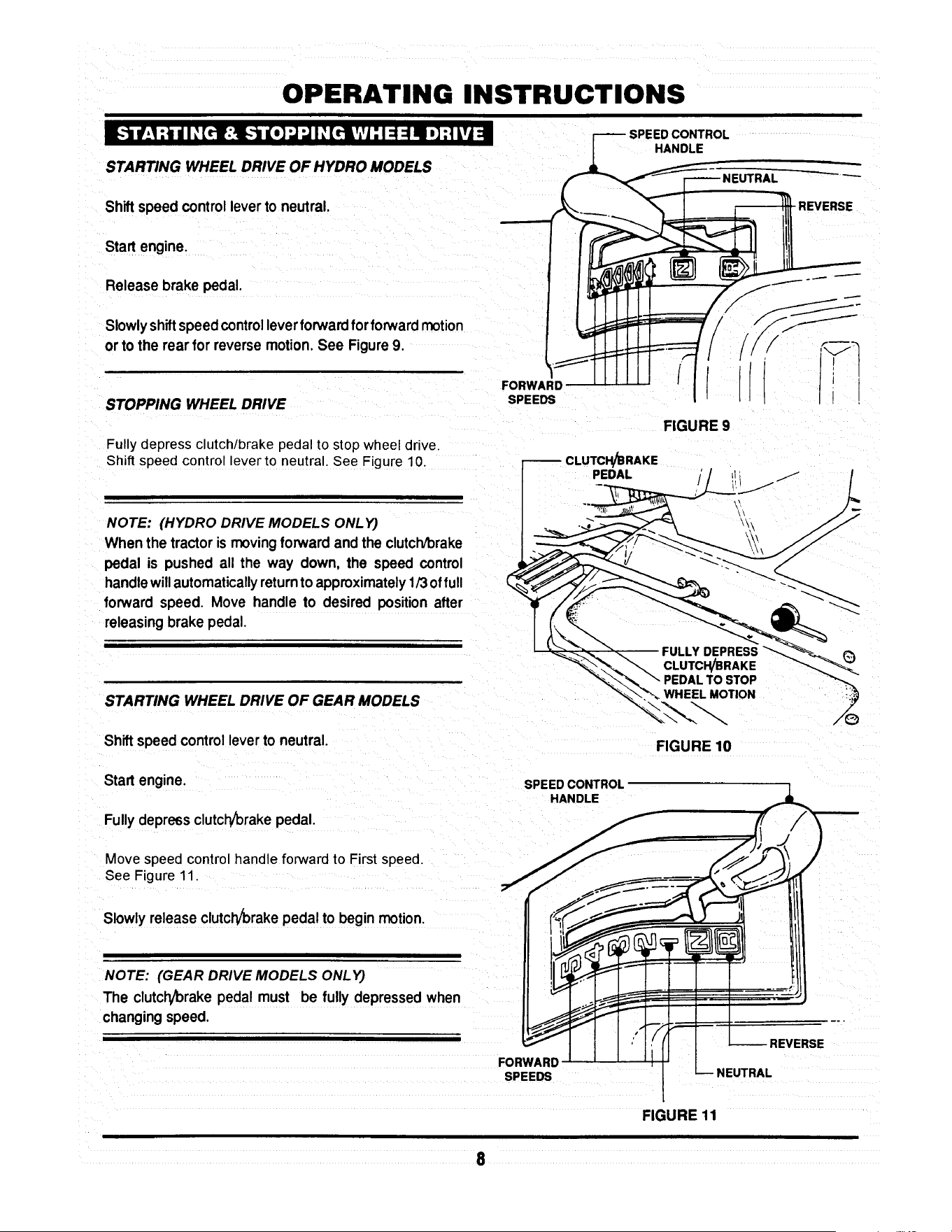
OPERATING INSTRUCTIONS
_._ net :_unlI: [_lr:l-_ n[o]"J"JI _[riYl: 1:1=1nl ,] ;1Lvi=
STARTING WHEEL DRIVE OF HYDRO MODELS
Shift speed controllever to neutral.
Start engine.
Release brake pedal.
Slowlyshiftspeed controlleverforwardfor forwardmotion
or to the rear for reverse motion.See Figure9.
STOPPING WHEEL DRIVE
Fully depress clutch/brake pedal to stop wheel drive.
Shift speed control lever to neutral. See Figure 10.
NOTE: (HYDRO DRIVE MODELS ONLY)
When the tractor is moving forward and the clutch/brake
pedal is pushed all the way down, the speed control
handlewillautomaticallyreturnto approximately1/3offull
forward speed. Move handle to desired positionafter
releasing brake pedal.
STARTING WHEEL DRIVE OF GEAR MODELS
Shiftspeed controlleverto neutral.
Start engine.
Fullydepressclutch/brakepedal.
Move speed controlhandle forward to Firstspeed.
See Figure 11.
Slowly release clutch/brakepedal to begin motion.
FORWARD
SPEEDS
CLUTCH/BRAKE
PEDAL
SPEED CONTROL
HANDLE
HANDLE
REVERSE
I
FIGURE 9
CLUTCH/BRAKE
PEDAL TO STOP
WHEEL MOTION
FIGURE 10
NOTE: (GEAR DRIVE MODELS ONLY)
The clutch/brake pedal must be fully depressed when
changingspeed.
FORWARD
SPEEDS
REVERSE
NEUTRAL
FIGURE 11
8

OPERATING INSTRUCTIONS
_-'lmmr.1:_mnlI _[rt::lE._m go] ..J..JI _[it L',[olV,'J=1:l :| mF_,lp]=l
STARTING MOWER BLADE
Start engine.
PULL BLADE ENGAGEMENT
LEVER UP TO "ON" TO
START MOWER BLADE(S)
ON
Raise blade engagement leverto "ON". See Figure 12.
STOPPING MOWER BLADE
Move blade engagement leverto "OFF". See Figure 12.
I_-.1:a / dI ,_[rl:Ji :t :1al:f.!,.-] I _'[rll ".,/:I:t [1:1 ::El [4::1
SETTING PARK BRAKE
ENGAGEMENT
LEVER
FIGURE 12
PEDALALL
PARK BRAKE
LEVER
Fullydepress clutch/brake pedal.
Movepark brake lever up into slot. See Figure 13.
Release clutch/brake pedal.
RELEASING PARK BRAKE
Fully depress clutch/brake pedal. The park brake lever
will release automatically.
MOVE PARK
LEVER"UP"TOENGAGE
PARK BRAKE
FIGURE 13
I :{o] ! q I _[ttl /; f-Till I[Ol:llV,'| 1111:I =1_[d I _I ::l[o]d =1
ROLLING HYDRO MODELS
ROLL RELEASE --
CONTROL
With engine "OFF", move to rearof tractor.
Movethe roll release control to the right and down. This
disengages the hydro transmission. See Figure 14.
Move tractorto desired location.
Moveroll release controlupandtothe leftto engage hydro
transmission
Set park brake.
NOTE:
The transmission will not propel the tractor if it is left in the
"ROLL" position.
\
\
\
ENGAGED
POSITION
FIGURE 14
POSITION

OPERATING INSTRUCTIONS
ROLLING GEAR DRIVE MODELS GEARDRIVEMODELSHOWN
With engine 'OFF', fullydepressclutcl_/brakepedal.
Place speed controllever in the neutral(N) position.See
Figure 15.
Release clutch/brakepedal and movetractorto desired
location.
Setparkbrakeandplacespeedcontrolleverintoaforward
speed.
m:_,_[_1I: [rl_]: t,J=i =1,]=1il _=[,, lo_ia=
/
FIGURE 15
1997 MODEL YEAR SHOWN
-SPEED
CONTROL
HANDLE
RAISING CHUTE DEFLECTOR for CLEARANCE
THROUGH GATES or TRANSPORTS
Remove wing nuts and flat washers, securing chute
deflector to deck. See Figure 16.
Raise chute deflector and reinstall flat washers and wmg
nuts onto studs to prevent loss.
Transport tractor to desired location.
Never attempt to operate mower without chute
deflector secured In the down position.
WING NUT
_,,._ FLAT WASHER
CHUTE DEFLECTOR
MUST BE IN THE "'DOWN"
POSITION BEFORE
OPERATING MOWER
FIGURE 16
i]I o_LuZ,,._dI _(_ub • dI _(_: I _ [_: b •
ADJUST CUTTING HEIGHT for all DECKS
Depresslock button on deck liftlever. See Figure17.
Raiseor lower deck to anyof six positions as desired.
DEPRESS LOCK ---I
( 15.I.oPO::_ON__s,
CUT
FIGURE 17
10

OPERATING INSTRUCTIONS
I / I ",.Z.."_l] _I ;l [*;'i'l I _[rII
For best results,use the followingtips when mowing.
When mowing,cutonly 1/3 of grassheight.Cuttinggrass
deeper couldbe harmfulto your lawn.
If cuttingextremelytall grass, make one cuttingwith the
deck in its highestcuttingposition,then lower deck to
desiredposition and a second cut.
Mow when lawnis dry.
Mow often.Shortergrassclippingsdecomposequicker.
Keep mower blades sharp. A dull blade tearsand shreds
grass instead of cutting. Your SNAPPER dealer can
sharpen blades as required.
Alternate mowing pattern to reduce the possibility of grass
matting.
Mow withenginespeed controlinthe "FAST" positionand
speed controlhandlein a "SLOW" position.
Clean deck, removing all grass clippingsanddebris from
the top and undersideof deck after each use.
V'_ltl'_1!W_.!:] il =f;_*-[*4 =b'_._*]:! I $1
The SNAPPER Series D LAWN TRACTOR can be equipped with a variety of accessories that increase its versatility.
The accessories available for each model are listed in the chart below. Contact an authorized SNAPPER dealer for
ordering any of the accessories desired.
AVAILABLE
ACCESSORIES
Thatcherizer
Dethatcher
Lawn SweeperDethatcher
Lawn Sweeper
Aerator
Broadcast Spreader
Lawn Roller
Snow Blade*
46" DozerBlade SpringTrip****
Dozer Blade Support Kit
2-Stage Snow Thrower**
38" Snow Thrower....
Snow Thrower Support Kit
OPPLT Debris Blower****
Hitch/Subframe Kit
Weight Kit
Tire Chains
Ninja Recycling/Mulch Kit
38 Ninja Recycling/Mulch Kit
38 Wave Recycling/Mulch Kit
Single Bag Catcher***
38" Single Bag Catcher
Dump Cart
Twin Bag Catcher......
38" Twin Bag catcher
Adapter Mounting Kit
Gage Wheel Kit
Utility Trailer
Bag-N-Wagon
Bag-N-Wagon Hitch Kit
LT120G30DB
6-1247
6-1912
6-1914
6-1913
6-1911
6-1916
6-1915
NA
6-1881
NA
NA
6-1880
NA
6-1883
6-1879
NA
NA
6-1254
NA
NA
6-0942
NA
6-0697
NA
NA
6-1334
6-1157
6-1910
NA
NA
NLT120G30DB
6-1247
6-1912
6-1914
6-1913
6-1911
6-1916
6-1915
NA
6-1881
NA
NA
6-1880
NA
6-1883
6-1879
NA
NA
6-1254
NA
NA
6-0942
NA
6-0697
NA
NA
6-1334
6-1910
NA
NA
LT125G38DB
6-1247
6-1912
6-1914
6-1913
6-1911
6-1916
6-1915
NA
6-1881
NA
NA
6-1880
NA
6-1883
6-1879
NA
NA
NA
6-1878
6-1877
6-1886
6-1886
6-0697
NA
6-1888
6-1334
NA
6-1910
NA
NA
LT140H33DBV
LT145H33DBV
6-1247
6-1912
6-1914
6-1913
6-1911
6-1916
6-1915
6-1352
6-1881
6-1370
8-0560
6-1880
6-1371
6-1883
6-1879
6-1245
6-1085
6-1255
NA
NA
6-0943
NA
6-0697
6-0946
NA
6-1334
NA
6-1910
6-0947
6-1308
* Requires Dozer Blade Su;_port Kit .......... ***Requires Adapter Mounting Kit
** Requires Snow Thrower Support Kit ...... ****Requires Hitch/Subframe Kit
11
LT145H38DBV
6-1247
6-1912
6-1914
6-1913
6-1911
6-1916
6-1915
6-1352
6-1881
6-1370
8-0560
6-1880
6-1371
6-1883
6-1879
6-1245
6-1085
NA
6-1878
6-1877
NA
6-1886
6-0697
NA
6-1888
6-1334
NA
6-1910
NA
NA
NLT145H38DBV
6-1247
6-1912
6-1914
6-1913
6-1911
6-1916
6-1915
6-1352
6-1881
6-1370
8-0560
6-1880
6-1371
6-1883
6-1879
6-1245
6-1085
NA
6-1878
6-1877
NA
6-1886
6-0697
NA
6-1888
6-1334
NA
6-1910
NA
NA

TROUBLESHOOTING
STARTER WiLL NOT
CRANK ENGINE
ENGINE WILL NOT START
1.Battery dead. 1. Service battery.
2. Blown fuse. 2. Replace fuse.
3. Electrical connections loose or corroded. 3. Clean end check connections for good
contact..
4. Defective ignition switch. 4. Contact authonzed SNAPPER dealer.
1. Blade engagement lever in the "ON" position.
I 2. Park brake not set.
3. Fuel tank empty.
4. Engine needs choking.
! 5. Spark plug wire disconnected.
6. Battery weak or dead
7. Faulty intedock switch.
1. Operator not in seat.
2. Engine speed controlinthe "CHOKE" position.
3. Fuel tank empty.
4. Engine air pra-deaner and orair cleaner dirty.
5. Spark plug defective or gap set improperly.
6: Fuel filterstoppedup.
7. Water, debds or stale fuel in fuel system.
1. Excessive load onengine.
2. Engine air pre-deaner or air cleaner dirty.
3. Engineoil level low.
4. Enginecoolingfins end air screens excessivelydirty.
5. Spark plug faulty.
6. Water, debds or stale fuel in fuel system.
ENGINE STALLS AFTER
RUNNING
I
1. Move blade engagement lever to "OFF"
2. Set park brake.
3. Fill fuel tank with fresh fuel.
4. Move engine speed control to "CHOKE"
5. Place spark plug wire onto spark plug.
6. Service battery.
ENGINE LOSES POWER
ENGINE BACKFIRES WHEN
IGNITION KEY TURNED TO
"STOP"
EXCESSIVE VIBRATION 1. Damaged or bent mower blades.
2. Loose blade components.
3. Loose or missing air lift (if equipped).
TRACTOR WILL NOT MOVE
OR LOSS OF TRACTION
3. Low transmissionoil level. (Hydro modelsonly)
4. Shifter out of adjustment.
5. Traction ddve belt requiresadjustment.
6. Traction ddve beltrequires replacement.
7. Contact authorized SNAPPER dealer.
1. Sit in operator's seat.
2. Move engine speed control to "FAST"
3. Refill fuel tank with fresh fue!.
14. Clean or replace filters.
5. Service spark plug.
6. Replace fuel filter.
7. Drain and clean fuel system.
t. Lessen load.
2. Clean or replace filters.
3. Fill with engine oil to proper level.
4. Clean free of all debns.
5. Service spark plug.
6. Drain and clean fuel system.
1. Engine speed control set too "FAST". 1. Set engine speed control to "SLOW" and
allow engine to idle. Then, turn key to "OFF".
1. Service mower blede(s).
2. Service and tighten loose parts.
3. Replace airlifts. Tighten to proper torque.
.Speed control handle in the neutral "N" position. 1. Place speed control in desired speed,
2. Roll release control in "ROLL" Positio n . 2. Move roll release control to the engaged
(Hydro Models Only) position.
3. Bdng oil to proper level.
4. Adjust shifter.
5. Adjust _'action drive belt.
6. Replace tractiondrive belt.
12

TROUBLESHOOTING
BLADE(S) NOT
CUllING
CUTTING GRASS 1.
IMPROPERLY
2.
3.
4.
5.
6.
7,
8.
POOR GRASS 1.
DISCHARGE
1.Blade engagement lever in the "OFF" position.
2, Blade belt requiresadjustment.
3. Blade belt requiresreplacement.
Uneven tire pressure.
Cuing height too low or high.
Engine speed too slow.
Forward speed too fast.
Deck side to side level requires adjustment.
Deck front to rear level requires adjustment.
Blade belt requires adjustment.
Blade belt requires replacement.
Engine speed too slow.
2. Forward speed too fast.
3. Grass is wet.
4 Excessively worn or damaged blade(s).
5. Build-up of grass clippings and debns under deck.
6. Improper blade(s) installed on deck.
7. Blade(s) installed improperly on deck.
BATTERY WILL NOT 1. Poor cable connections.
CHARGE
2. Bad battery cell(s).
OIL LEAKING
FROM TRANSMISSION
1. Move leverto the "ON"position.
2. Adjust mower belt.
3. Replace mowerbelt.
1. Bring to proper pressure.
2. Adjust cuttingheight.
3. Move engine speed oontrol to "FAST'.
4. Move speed controlto a slowerspeed.
5. Adjust side to side level.
6. Adjustfront to rear level.
7. Adjustblade belt tension.
8, Replace blade belt.
1. Move engine speed oontrol to "FAST".
2 Move speed control to a slower speed.
3. Mow when grassis dry.
4.Servicemower blade(s).
5.Cleandeck.
6.InstallproperSNAPPER blades.
7.Installbladesproperly,
I.Cean cablesand batteryterminals.
2. Replace with new battery.
3. Faulty alternator. 3. Contact engine manufacturer's dealer.
1. Loose or missing oil filler cap. (Hydro Models Only) 1. Check oil level and replace oil cap.
2. Leaking axle seals. 2. Contact authorized SNAPPER dealer.
3. Leaking at casing seal 3. Contact authorized SNAPPER dealer.
13

MAINTENANCE INSTRUCTIONS
SUBJECT
Engine
Engine
Engine
Air Pre-Cleaner
Air Cleaner
Spark Plug
Fuel Filter
Engine Cooling
System
Battery
Tires
Drive Belts
Mower Blades
Mower Deck
Mower
Deck
Lubrication
Points
Hydrostatic
Trans. Oil
SERVICE
TO BE PERFORMED
Check Oil Level
Initial Oil Change
Periodic Oil Change
Service Sponge Pre-
Cleaner Element
Replace Element
Replace Plugs
Replace Filter
Clean Shrouds & Fins
Check Electrolyte
Charge Battery
Check Pressures
Check For Wear And
Tension
Check For Wear And
Damage
Clean Debris
Accumulation
Clean Outside and
Underside
Grease or Oil
Check Oil Level
REFERENCE EACH 5 25 50 100 EACH
PAGES USE HOURS HOURS HOURS HOURS SEASON
Page 6 X
Pages 15 & 16 X
page 15 X*
Engine Manual X**
&Page 19
Engine X**
Manual.
Engine X
Manual.
Page 19 X
Engine Manual X**
& Page 20
Page 20 X X
Page 20 & 21 X
Page 6 X X
Pages 22-26 X X
Pages 20-21 X
i
Page 6 X X X
Page 6 X X X
Pages 17 &:18 X X
Page 15 X
*Change oil every 25 hours when operating under heavy load or high temperatures.
**Clean more often under dusty conditions or when air debris is present
TRACTOR
MODEL No.
LT120G30DB, NLT120G30DB
LTI25G33DB
LT140H33DBV, LT145H33DBV
LT125G38DB
LT145H38DBV, NLT145H38DBV
DRIVE BELTS
Engine to Transmission Engine to Deck Standard
2-8585 2-8793 1-8069
2-8585 2-9205 3-4168
2-8585 2-9205 3-4168
2-8585 3-5500 4-2998
2-8585 3-5500 4-2998
MOWER BLADES
NINJA
2-6597
2-4234
2-4234
14

MAINTENANCE INSTRUCTIONS
The hydrostictransmission does not normally require
maintainence,however,properoillevelshouldbeverified
sfter everyseason.
TO CHECK OIL LEVEL IN TRANSMISSION
Remove seat by removing seat adjustment knobs, See
Figure 18.
Lay seat forward. Be careful notto pullseatswitchwires
from the switch.
Disconnectnegative (black) battery wire from terminal
first!See Figure 19.
Disconnectpositive(red) battery wire from terminal last!
Remove batteryand battery tray. Transmissionis now
accessible.
\
REINSTALL
BATTERY
PER DECAL
\
FIGURE 18
SEAT
ADJUSTING
KNOBS
Clean any debris off of oil cap and top cover before
removiing fill cap. See Figure 20.
Before attempting any adjustments or repairs, STOP
the engine, remove the key, remove the spark plug
wire(s) from the spark plug(s) and secure wire(s)
away from plug(s).
Visuallycheck oil level.
Oillevelshouldbe approximately3/4" (+1/4")from topof
case. Ifthe level is lowerthan 3/4",add 10W30 motoroil
to bringthe levelup as required.
Replacefillcap.
Reinstallbattery tray.
NEGATIVE (-)
TERMINAL
(BLACK)
FIGURE 19
POSITIVE(÷)
TERMINAL
(RED)
Reinstall battery. See Figure 19.
Reinstalland adjust seat. See Figure18.
- 3/4" +1/4"
FIGURE 20
15

MAINTENANCE INSTRUCTIONS
MODELS L T120G30DB, NL T120G30DB,
LT125G33DB & LT125G38DB
These models are equipped with 12 & 12 1/2 hp engines
which are furnishes with extended oil drains. See Figure
21.
Raisetractorhood and tilt itforward.
Disconnectsparkplugwire. Securewire awayfrom soark
plug.
Put a brick or block of wood under deck wheel on opposite
side of oil drain.
Loosenoilfill cap on engine.
Placea 2 quart capacityflat containerbeneath end of oil
drain.
Removeoil plug.
Allowengineoilto drain completely.
After alloilhas drained, replace oilplugand fill enginewith
new motor oil as specifiedin Engine Owner's Manual.
MODELS LT140H33DBV, LT145H38DBV &
NL T145H38DB V
These models are equipped with 14 & 14 1/2 hp
engineswhichare furnished withFastexTM oildrains.See
Figure22.
Rotate drain body counterclockwise and pull out to open
drain.
Drainoil into a 2 quart container placed beneath end of oil
drain.
After all oil has drained, push drain body "IN" and rotate
clockwiseto close. Push drain cover over drain nipple.
Fill engine with new motor oil as specified in Engine
Owner's Manual.
NOTE:
Ifthetractor's engine is equipped withan oil filter, change
at everyoil change.Contactengine manufacturerdealer
for replacementfilter for particularengine.
ROTATE
CLOCKWISE AND
PULL OUT TO OPEN
16
FILLER
TUBE
OIL DRAIN
EXTENSION
\
FIGURE 21
FIGURE 22
PLUG
TO DRAIN OIL
L FILLER
TUBE
/
FASTEX'_
OIL DRAIN

MAINTENANCE INSTRUCTIONS
The followinglubricationpoints shouldbe servicedafter
each 25 operating hours to insure optimum performance
of the Series D Lawn Tractor.
FRONT WHEEL BEARINGS
Lubricateeach front wheel bearing through the grease
fitting on wheel hub. Using general purposegrease in a
greasegun, addgrease untilgreasepurgesfrom bearing.
See Figure 23.
AXLE SPINDLE
LUB RICATION
FITTING
AXLE SPINDLES
Lubricateeach axlespindlewith 1 shot ofgeneral purpose
grease. See Figure 23.
NOTE:
The R.H. spindle fitting faces forward and the L,H. spindle
fitting faces to the rear.
FRONT WHEEL BEARING
LUBRICATION FITTING
FIGURE 23
CLUTCH/BRAKE
PIVOT LUBRICATION
RTTING
CLUTCH//BRAKE PIVOT
The clutch/brake pivot is located on the L.H. underside of
the tractor and is lubricated with one shot of general
purpose grease. See Figure 24.
STEERING SECTOR GEAR
Lubricatewith a lightcoat of 30 wt. motoroil.See Figure
25.
STEERING SHAFT
Lubricatesteeringshaft wear pointswitha light coatof 30
wt. motoroil.
FIGURE 24
FUEL TANK
STEERING
SECTOR
SECTOR
GEAR
j"
17
FIGURE 25
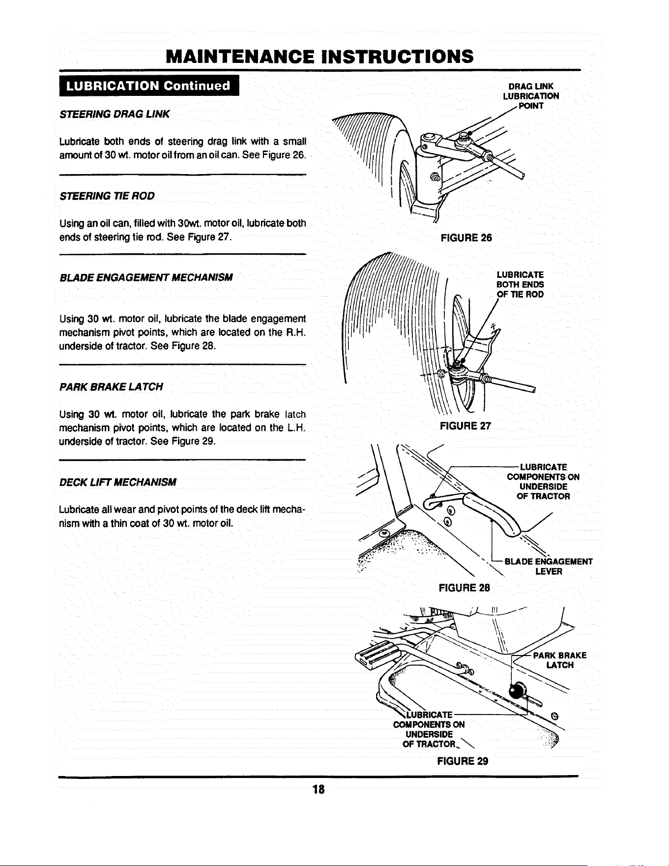
MAINTENANCE INSTRUCTIONS
STEERING DRAG LINK
Lubricateboth ends of steering drag link with a small
amountof 30 wt. motoroilfrom anoilcan. See Figure26.
STEERING TIE ROD
Usingan oil can,filledwith30wt. motoroil, lubricateboth
endsof steeringtie rod. See Figure27.
BLADE ENGAGEMENT MECHANISM
Using30 wt. motor oil, lubricatethe blade engagement
mechanismpivot points,which are locatedon the R.H.
undersideof tractor.See Figure28.
PARK BRAKE LATCH
Using 30 wt. motor oil, lubricatethe park brake latch
mechanismpivot points, which are located on the L.H
undersideof tractor.See Figure29.
DECK LIFT MECHANISM
Lubricateallwear and pivotpoints ofthe deck liftmecha-
nismwith a thincoat of 30 wt. motor oil.
DRAG UNK
LUBRICATION
FIGURE 26
::::C'o:
FIGURE 27
LUBRICATE
COMPONENTS ON
UNDERSIDE
OF TRACTOR
".BLADE ENGAGEMENT
\
LEVER
FIGURE 28
PARK BRAKE
LATCH
LUBRICATE
COMPONENTS ON
UNDERSIDE
OF TRACTOR._
FIGURE 29
18

MAINTENANCE INSTRUCTIONS
The componentslistedshouldbe servicedon a regular
basisto insurethattheyare intopworkingcondition.Refer
to SERVICE SCHEDULE on Page 14 for recommended
serviceintervals.
AIR CLEANER
ENGINE AIR PRE-CLEANER
Theengineairpre-cleanershouldbe removedandcleaned
every25 operatinghours.See Figure30. Referto Engine
Owner'sManual for specificcleaninginstructions.
ENGINE AIR CLEANER
The engine air cleaner element shouldbe removedand
replacedevery 25 operatinghours.See Figure30. Con-
tactenginemanufacturer'sdealerfor correctreplacement
element.
ENGINE
AIR PRE.CLEANER
\
\
FIGURE 30
FUEL
TANK
SPARK PLUG
Removeand replaceenginesparkplugafter 100 operat-
ing hours. Refer to EngineOwner's Manual for correct
replacementplugand gap specifications.
FUEL FILTER
Theenginefuelfiltershouldbe replaced every100 oper-
atinghours.Remove the fuel filter as follows:
NOTE:
Itmay be necessary to drainthe fuel tank before removing
fuel filter to preventexcessivespillageof gasoline.
HOSE CLAMR
Raisetractorhood.
Removesparkplugwire(s)andsecureawayfrom plug(s).
Locate fuel filter. Remove hose clamps and fuel hoses
from bothsides of fuel filter. See Figure31.
NEW FUEL FII
PART No. 1-4359
FIGURE 31
Installnew fuel filtei"part number1°4359. See Figure32,
Fillfueltankwith freshgasoline.Refer to EngineOwner's
Manualforfuel specifications.
Reconnectsparkplugwire(s).
FIGURE 32
Lowertractor hood.
19

MAINTENANCE INSTRUCTIONS
ENGINE COOLING SYSTEM
The engine coolingsystemconsists of an engineshroud
and engine fins.These shouldbe kept clean and free of
debrisas needed or clean at least every 100 operating
houm.
The batteryshouldbe servicedevery25 hours of opera-
tion.
Raiseoperator'sseat.
Removethe two adjustingknobs.
Remove seat assemblyand moveforward.Use care not
to disconnectwiresfrom seat switch.See Figure33.
Removenegative(-) cable first.
Removepositive(+) cable.
REMOVE ADJUSTING
KNOBS AND MOVE _ / --
S ,TFO.WA.0, I / ,7
f
FIGURE 33
CHECKING BATTERY ELECTROLYTE
Carefully remove battery cell covers.
Visually check electrolyte level in each cell. Level shouldbe
1/8" to 3/8" above cell plates up to the fill rings.
ELECTROLYTE
3116" ABOVE
CELL PLATES
FIGURE 34
2O

MAINTENANCE INSTRUCTIONS
Usingdistilledwater, fill cells as needed to 1/8" to 3/8"
above cell plates.
Replace cell covers.
Charge battery if required.
Install positive(+) cable first.
Install negative(-) cable last.
Install seat assembly over battery and secure in position
with adjusting knobs. Leave knobs loose.
Lower operator's seat and adjust to desired position.
Raise seat and tighten adjusting knobs.
BATTERY CHARGING
The engine is equipped with a flywheel alternator to
charge the battery. If the tractor is not run regularly,
connect the battery to a charger monthlyto maintainthe
specific gravity at 1.250 or higher. If this reading falls
below 1.175, the batteryliquidmay freeze whentempera-
turesdropto around zero degrees F. To charge, connect
perinstructionsfumishedwithcharger,If time allows, slow
charge at 1 amp for ten hours, or as an alternate, fast
charge at 3 amps forfour hours. Observe all precautions
while charging.
.LEY
TRACTION DR! VE-BEL T
Check the tractiondrivebeltfordamage andwear after25
operatinghours. The traction drive belt is locatedon the
undersideofthe tractorandspansfromthe enginepulley's
top groove to the transmissionpulley. See Figure 35.
TRACTION --
DRIVE BELT
FIGURE 35
21

MAINTENANCE INSTRUCTIONS
Should the tractiondrive belt show signs of excessive
wear or damage, replace.
MOWER DECK REMOVAL
Placetractoron a firm,levelsurfacesuchasadrivewayor
garage floor and engage park brake.
Turnengine "OFF".
Raise hoodand removesparkplugwirefromsparkplug.
Securesparkplugwireawayfromsparkplug.See Figure
36.
\
UFT ROD
FRONT
UFT ARM
FIGURE 37
HAIR PIN
Lowerdeck to lowestsetting.
Disconnectdeck liftrodfromfrontliftarm. See Figure37
Removehair pinsfromfrontdeckhangerrod.See Figure
38.
RIGHT
SIDE
LO;T
Turnwheelsto the left, k'-,
Hold front of deck"UP"andslidefrontdeckhangerrodto ""'_%_- "'_
the right and out. FRONT DECK /"f_ _.._/_/_
HANOERROO/
Lowerfront of deck to ground. /
FRONT
Remove hair pin and flat washerfrom reardeck hanger LIFT HAIRPIN
bracket on bothsidesof tractor.See Figure39. ARM
FIGURE 38
SECURE WIRE
AWAYFROMPLUG ! t_
I
S
FIGURE 38
__.//_ SECTOR I
PIN AND WASHER_ _. ,
FROM BOTH _ /
../_.._.TO R PLATES "_' _.__L_
FIGURE 39
22
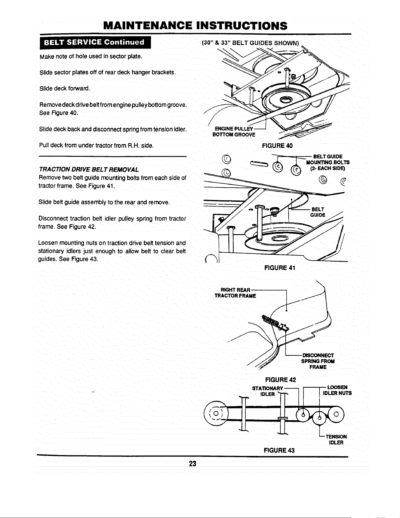
MAINTENANCE INSTRUCTIONS
Make note of hole used in sector plate.
Slide sectorplates off of rear deck hanger brackets.
Slide deck forward.
Remove deck drive beItfrom engine pulley bottom groove.
See Figure 40.
Slidedeck back and disconnect springfrom tension idler.
Pull deck from under tractor from R.H. side.
TRACTION DRIVE BELT REMOVAL
Remove two belt guide mounting bolts from each side of
tractor frame. See Figure 41.
Slide belt guide assembly to the rear and remove.
Disconnect traction belt idler pulley spring from tractor
frame. See Figure 42.
Loosen mounting nuts on traction drive belt tension and
stationary idlers just enough to allow belt to clear belt
guides. See Figure 43.
(30" & 33" BELT GUIDES SHOWN)
FIGURE 40
FIGURE 41
RIGHT REAR
TRACTOR FRAME
FIGURE 42
_I'ATIONARY------1 I-_1 _ LOO6EN
II I
IDLER
FIGURE 43
23
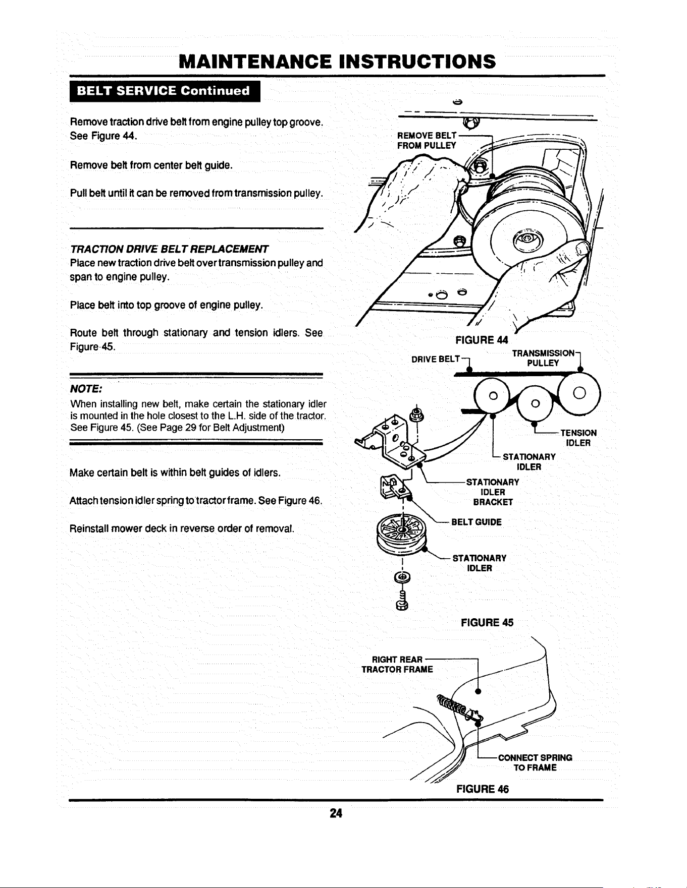
MAINTENANCE INSTRUCTIONS
Removetractiondrivebeltfromenginepulleytop groove.
See Figure44.
Removebelt from centerbeltguide.
Pullbelt untilitcan be removedfrom transmissionpulley.
TRACTION DRIVE BELT REPLACEMENT
Place new traction drive belt over transmission pulley and
span to engine pulley.
Place belt intotop grooveof enginepulley.
REMOVE
FROM PULLEY
Route belt through stationary and tension idlers. See
Figure45.
FIGURE 44
PULLEY
NOTE:
When installing new belt, make certain the stationary idler
is mounted in the hole closest to the L.H. side of the tractor.
See Figure 45. (See Page 29 for Belt Adjustment)
Make certainbelt is withinbeltguidesof idlers.
Attachtensionidlerspringtotractorframe. See Figure46,
Reinstall mower deck in reverse order of removal.
TENSION
IDLER
STATIONARY
IDLER
STATIONARY
IDLER
BRACKET
DE
I
RIGHT REAR
TRACTOR FRAME
STATIONARY
IDLER
FIGURE 45
\
\
!CTSPRING
TO FRAME
FIGURE 46
24

MAINTENANCE INSTRUCTIONS
30" & 33" DECK DRIVE BELT REMOVAL AND
REPLACEMENT
Inspect deck drive belt for excessive wear and damage
after every 25 operating hours. Replacement procedures
are as follows:
SPINDLE PULLEY
COVER
REMOVE
IDLER
Place tractoron a firm, level surface.
Turn engine "OFF".
Raise hood, remove spark plug wire from spark plug and
secure wire away from spark plug.
Remove mower deck.
Remove deck belt idler pulley. See Figure 47.
Remove spindle pulley cover. See Figure 47.
Remove old belt.
Replace with new belt, part number 2-2786 (30"), 2-6546
(33"), in reverse order.
/
/
FIGURE 47
SPINDLE----]
PULLEYFq L
IDLERPULLEY
FIGURE 48
Adjustidler pulley belt guide if necessary to obtain 1/16"
clearance between belt and belt guide. See Figure 48.
REMOVE IDLER ---_
38" DECK DRIVE BEL T REMOVAL/REPLACEMENT
Movetractorto a firm, levelsurface.
Turn engine "OFF".
Raise hood, remove spark plug wire from spark plug and
secure wnreaway from spark plug.
Remove deck from tractor.
Remove spindle belt guard. See Figure 49.
Remove tension idler. See Figure 49.
FIGURE 49
BELT GUARD
Remove old belt. _ ,__ . _ TENSION
p' 1,1,c,E, .cE\
Replace new belt, part number 3-5500, in reverse order. I.,_ (TYP'cAL) k_y(F_-'_o_
See Fngure 50 _pupl_ _ __._
FIGURE 50
25

MAINTENANCE INSTRUCTIONS
" W.ARNING " A I
Blades are extremely sharp and can cause severe I
injury. Wear heavy leather gloves when handling or I
working around blades. DO NOT use a blade that is I
excessively worn or damaged. I
_Ib WARNING --_
I Never use a cutting blade that shows signs oq
excessive wear or damage. Refer to Figure 4.5. Wear I
heavy leather gloves when handling or working I
around cutting blades. Blades are extremely sharPl
and can cause severe injury. I
STANDARD BLADE WEAR LIMITS
All mowerblades shouldbe checked for excessivewear
anddamage before each use.See Figure52.
30" &33"MOWER BLADEREMOVAL/REPLACEMENT
Movetractorto a firm, levelsurface.
Turn engine "OFF".
-_ -_ _ B- WEARUMIT
__ CUTTINGEDGE
-_.._ WORN
_--- C- DANGEROUSCONDITIONI
DO NOT USEON MOWERI
FIGURE 52
I11
Raise hood, remove spark plug wire from spark plug and r-_ NUT BLADE-JJ-_ ./1
secure wire away from spark plug. 1 _-FF-'-LOCK WASHER I/I _ I
e ove eo ,ro traOor.
Install new 30" blade, pad number 1-8069, or 3-4168 for _J/ "_/
33" blade mounting bar. v__
BLADEMOUNTINGBOLTS
FIGURE 53
28

MAINTENANCE INSTRUCTIONS
Install blade mounting bolts, internal tooth lock washers
and nuts. See Figure 53
Torque blade to 30 to 40 Ft, Lbs.
38" STANDARD MOWER BLADE REMOVAL AND
REPLACEMENT
Move tractor to a firm, level surface.
Turn engine "OFF".
Raise hood, remove spark plug wire from spark plug and
secure wire away from plug.
Remove mowing deck from tractor.
Carefully position deck to access blades.
Remove blade mounting nut and cone washer from each
blade. See Figure 54.
Install new blades, part number 4-2998.
Secure blades with cone washers and mounting nuts. See
Figure 54.
Torque blade to 70 to 80 Ft Lbs.
(2- REQUIRED)
CONE
I WASHER
_ MOUNTING NUT
FIGURE 54
27

MAINTENANCE INSTRUCTIONS
SHARPENING STANDARD BLADE(S)
Blades should be kept sharp at all times. When the
blade(s) are dull, cut grass will be ragged and lawn will
usuallyturn brown.Sharpen standardbladesas follows:
Movetractorto a firm, levelsurface.
Tum engine "OFF'.
Raise hood,removesparkplugwirefromsparkplugand
securewire away from plug.
Remove mowing deck fromtractor.
Remove mower blade(s)
Inspectfor excessivewear or damage.
FIGURE 56
Never use a blade that shows signs of
exceaslve wear or damage. Refer to Figure
52 for standard blade wear limits.
Sharpenstandardmowerblade(s) at 25° angle+3°. See
Figure 56.
NINJATM BLADE WEAR LIMITS
The NinjaTM recyclingblade requiresmorefrequentser-
vice intervalsthan standardblades. Check the NinjaTM
recyclingblade for excessivewear or damageafterevery
use. See Figure 57.
NINJATM BLADE SHARPENING
The NinjaTM recycling blade requires more frequent
sharpening than standard blades due to its recycling
method.
Remove the NinjaTM blade by followingproceduresfor
standardblade removal.
Inspectthe NinjaTM bladefor excessivewear or damage.
See Figure57 for NinjaTM bladewear limits,
B- WEAR UMIT
(CRACKS OR NOTCHES
BEGIN TO APPEAR)
_ DANGEROUS CONDITIONI / _2._ ._,' 'It
DO NOT USE ON MOWERI "_ "_ _
FIGURE 57
28

MAINTENANCE INSTRUCTIONS
Never use a blade that shows signs of
excessive wear or damage. Refer to Figure
57 for NinJaTM blade wear limits.
Sharpen allcuttingedges ofthe NinjaTM recycling blade at
27° (+3°, -2 °) for optimum performance. See Figure 58.
Reinstall sharpened NinjaTM blade in reverse order of
removal.
Torque mounting bolts or nuts to proper standard blade
torque value for deck being serviced.
BLADE
FIGURE 58
Should a gradual loss of traction be noticed, it may be
necessary to adjust the traction drive belt tension. Adjust
as follows:
BELT
BRACKET
MORE
Movetractor to a firm, level surface.
Turn engine "OFF".
Raise hood remove spark plug wire from spark plug and
secure wire away from plug.
Remove mowing deck.
Remove the traction drive belt stationary idler mounting
bolt. See Figure 59.
Move the stationary idler one hole toward right side of
tractor for more tension.
NOTE:
Note the orientation of belt guide and make certain it
remainsin the same orientationafter moving idler.
NOTE:
Should less tension be required move stationaryidler
towardsright side of tractor. See Figure59.
|
IDLER
STATIONARY
MOUNTING BOLT
LESS
BELT GUIDE-
MAKE CERTAIN BELT
GUIDE ORIENTATION
IS MAINTAINED.
I
÷
STATIONARY
IDLER
MOUNTING BOLT
FIGURE 59
29
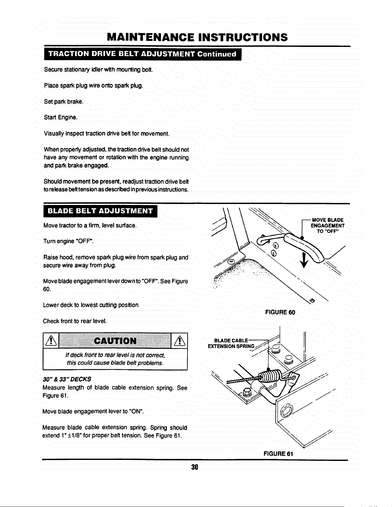
MAINTENANCE INSTRUCTIONS
Securestationaryidlerwith mountingbolt.
Place sparkplug wire onto spark plug.
Setpark brake.
Start Engine.
Visuallyinspecttractiondrive beltfor movement.
When properlyadjusted,the tractiondrivebelt shouldnot
have any movement or rotationwith the engine running
and park brake engaged.
Shouldmovement be present,readjusttractiondrive belt
to releasebeittension asdescribedinpreviousinstructions.
Movetractorto a firm, levelsurface. /
Turn engine"OFF'.
Raisehood,remove sparkplug wirefrom sparkplug and
securewire away fromplug.
Movebladeengagement leverdownto"OFF".See Figure ._._:
60. -::
E
ENGAGEMENT
TO "OFF"
Lower deckto lowest cutting position
Checkfrontto rear level.
If deck front to rear level is not correct,
thiscouldcause blade beltproblems.
30" & 33" DECKS
Measure length of blade cable extensionspring. See
Figure61.
Moveblade engagement lever to "ON".
Measure blade cable extension spring.Spring should
extend1"+_1/8"for properbelttension.See Figure61.
EXTENSION SPRING
FIGURE 60
FIGURE 61
3O

MAINTENANCE INSTRUCTIONS
To adjust tension, remove extension rod mountingbolt
and nut. See Figure62.
Move extension rodto next hole towards rear of deck and
securewith mountingbolt and nut. MOUNTING-
NUT & BOLT
Measure extension spring with blade engagement lever in
the "ON" and "OFF" positions. See Figure 61. Continue
adjustment until tension is correct.
I
-_LEAST TENSION/d
• _L / MOSTTENSlON
"-_ //
FIGURE 62
NOTE:
Before adjusting deck, bring tire pressureto properpsi.
Front12 psi, Rear 10 psi.
SIDE TO SIDE LEVEL
Movetractorto a firm, level surface.
Turn engine "OFF".
Raisehood, remove spark plugwire from spark plug and
securewire away from plug.
Move blade engagement lever to "OFF".
Place a piece of angle iron under center rear of deck.
SECTOR
PLATE
__ REMOV_ _
Remove hair pins and washers securing rear of deck to
sector plates. See Figure 65.
FIGURE 65
31

MAINTENANCE INSTRUCTIONS
Slidesectoroffof pinsandcarefullylowerdeckontoangle
iron.
33" DECK SHOWN
Rotate.blade(s) untilblade tipsare at each sideof deck.
•Measuredistancefrom blade tipto flooron each sideof LMEASUREFROM
deck. BLADE TIPS
TO FLOOR
Bladetips shouldbe within1/8"ofeach otherfor thedeck
to be consideredlevel. See Figure66.
If measurementdiffersmore than 1/8",adjustas follows:
Loosenfrontliftarm pivotboltonfrontof rightsiderail.See
Figure67.
NOTE:
The 38" deck does not incorporatea pivotbolt.
PIVOT BOLT
LOOSEN
SHOULDER BOLT
_-_ ANGLE IRON
FIGURE 66
f
Looseneccentricshoulderbolt. See Figure67.
Turneccentric"UP"or'DOWN" as requiredto leveldeck.
See Figure67.
Tighteneccentricshoulderbolt.
Tighten pivotbolt.
J
ECCENTRIC
AS REQUIRED
FIGURE 67
Place sector plates back onto rear lift arms and secure
withwashersand hairpins. SECTORPLATES
Make certainsector plates are mountedin the same _---_,,, ,,__ _;¢__ ________
holeson each side forproper frontto rearlevel.
FRONT TO REAR LEVEL-SECTOR PLATES --_-- "_-_
LOWEST OE
Removehairpinsand washerssecuringsectorplatesto
rearliftarms.See Figure 68. _ ~ _DECI(-S'_ING _ -------_-SETTING
Movesectorplate as requiredto raiseorlowerdeck. ___.-__ .)_1--'_ I_11_1_
DECK
REMOVE'
HAIR PIN & WASHER
FIGURE 68
32
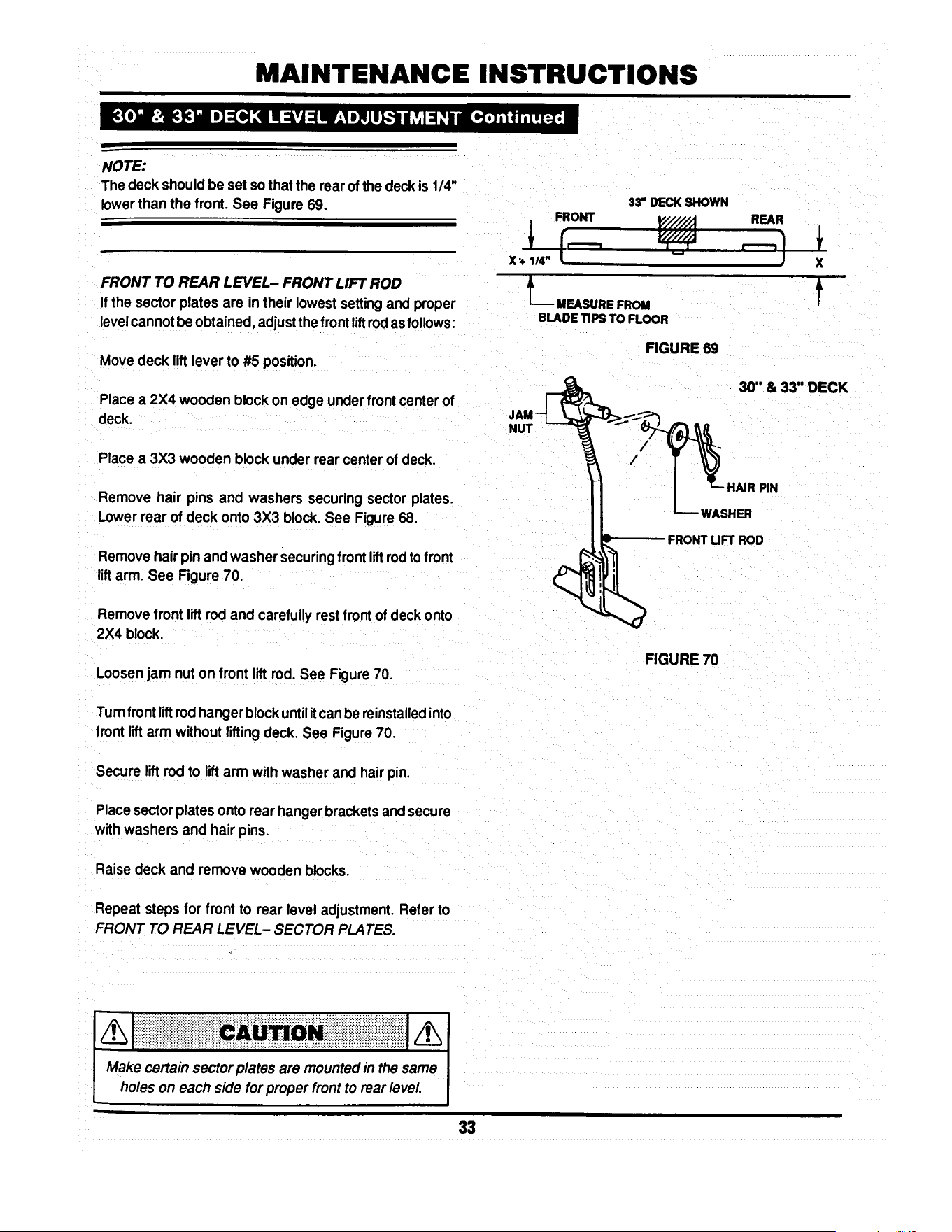
MAINTENANCE INSTRUCTIONS
NOTE:
Thedeck shouldbe set sothat the rearofthe deck is 1/4"
lowerthan the front.See Figure69.
FRONT
X • 1/4"
33" DECK SHOWN
P'/////;! REAR
FRONT TO REAR LEVEL- FRONT LIFT ROD
If the sector plates are in their lowest setting and proper L__ MEASUREFROM
level cannot be obtained, adjust the front liftrod as follows: BLADETIPSTOFLOOR
x
f
FIGURE 69
Movedeck lift leverto #5 position.
30" & 33" DECK
Place a 2X4 woodenblockon edge underfrontcenter of
deck.
Place a 3X3 wooden blockunder rearcenter of deck.
NUT
/
/
Remove hair pins and washers securingsectorplates.
Lowerrear of deck onto3X3 block. See Figure68.
Removehairpinand washer securingfrontliftrodtofront
liftarm. See Figure 70.
Removefront lift rod andcarefullyrestfrontof deckonto
2X4 block.
Loosenjam nuton front liftrod.See Figure70.
•HAIR PIN
_ FRONT UFT ROD
FIGURE 70
Turnfrontliftrodhangerblockuntilitcan be reinstalledinto
frontlift arm withoutliftingdeck. See Figure70.
Secure lift rodto liftarm withwasher and hair pin.
Placesector platesonto rearhanger bracketsandsecure
withwashers and hair pins.
Raisedeck and remove wooden blocks.
Repeat steps for frontto rear level adjustment.Referto
FRONT TO REAR LEVEL- SECTOR PLATESo
Make certainsector plates are mountedin the same I
holes on each sidefor proper front to rear level. I
33

MAINTENANCE INSTRUCTIONS
NOTE:
Before adjusting deck, bring tire pressureto proper psi.
Front 12 psi, Rear 10 psi.
SIDE TO SIDE LEVEL
FRONT OF TRACTOR
BLOCK
Move tractor to a firm, level surface.
Turn engine "OFF".
Raise hood, remove spark plug wire from spark
plug and secure wire away from plug.
Move blade engagement lever to "OFF".
Place a 2-112" tall block under the front of the deck
centered between the front lift arms. See Fig 70a.
Place a 1-3/4" tall block under the rear of the
deck in the center. See Fig 70a.
Position the blades as shown in Fig 70a and lower
the deck onto the blocks.
1-3/4"TALLBLOCK_--_
FIGURE 70a
BLADESORIENTATEDFORSIDE-TO-SIDELEVELCHECK
38" DECK
Disconnect the front lift rod and the rear hanger
plates. See Fig 68 on page 32 and Fig 70b.
NUT
Put the lift lever in the 3rd position from low cut.
Measure the distance from each blade tip to the
floor. The measurements should be within 1/8"
of each other. (Factory setting)
If the difference is less than 1/8", go to next
section, Front-to-rear level.
If the difference is more than 1/8", adjust as
described in the following steps.
FRONT UFT
FIGURE 70b
Loosen the front adjuster nut until adjuster
moves freely. Then, tighten the nut until the
adjuster moves only when moderate force is
applied to one side of the deck. See Fig. 70c.
Adjust the side-to-side level of the blade tips by
moving one side of the deck up or down as
needed to obtain 118" or less side-to-side deck
level.
After leveling deck, re-tighten the adjuster nut
to from 30 to 40 ft-lbs.
FIGURE 70c
\
_ADJUSTER
NUT
33A

MAINTENANCE INSTRUCTIONS
Attach the rear hanger plates to the hole that
most closely aligns with the pin on the deck lift
bracket. Secure with washer and hair pin.
/h[ i !! !!ii! iiiii!i i ii! !i!!!i! !i Iiiiic i! !i ! Ni i ii!i Mii iii iii ii i i i i i i iiiiiiiiiiiiiii!j/hi
Make certain sectorplatesare mountedin the same I
holes on each side for proper frontto rear level J
FRONT OF TRACTOR
Adjust the swivel on the front lift rod until it
lines up with the hole in the front lift bracket.
(make sure the lift rod is at the top of the slot in
the deck bracket) Secure with hair pin.
FRONT TO REAR LEVEL
Position the blades as shown in Fig. 70d.
Measure the distance from the left front blade
tip to the ground and from the right rear blade
tip to the ground. The front left blade tip should
be between 1/8" and 3/8" higher than the right
rear (factory setting). If it is between 1/8" and
3/8" you are finished with adjustment.
If it is not within specifications, adjust by raising
or lowering the front of the deck using the
the swivel on the front lift rod. Turning the swivel
clockwise will raise the front of the deck. Turning
the swivel counter-clockwise will lower the front of
the deck.
BLADE TIP
\
\
RIGHT REAR BLADE TIP
FIGURE 70d
BLADESORIENTATEDFORFRONT-TO-REAR
LEVELCHECK
NOTE:
The deck should be set sothat the rear of the deck is 1/4"
lowerthan the front. See Fig. 70e.
33" DECK SHOWN
FRONT
JL MEASURE FROM
BLADE TIPS TO FLOOR
REAR
FIGURE 70e
X
f
33B
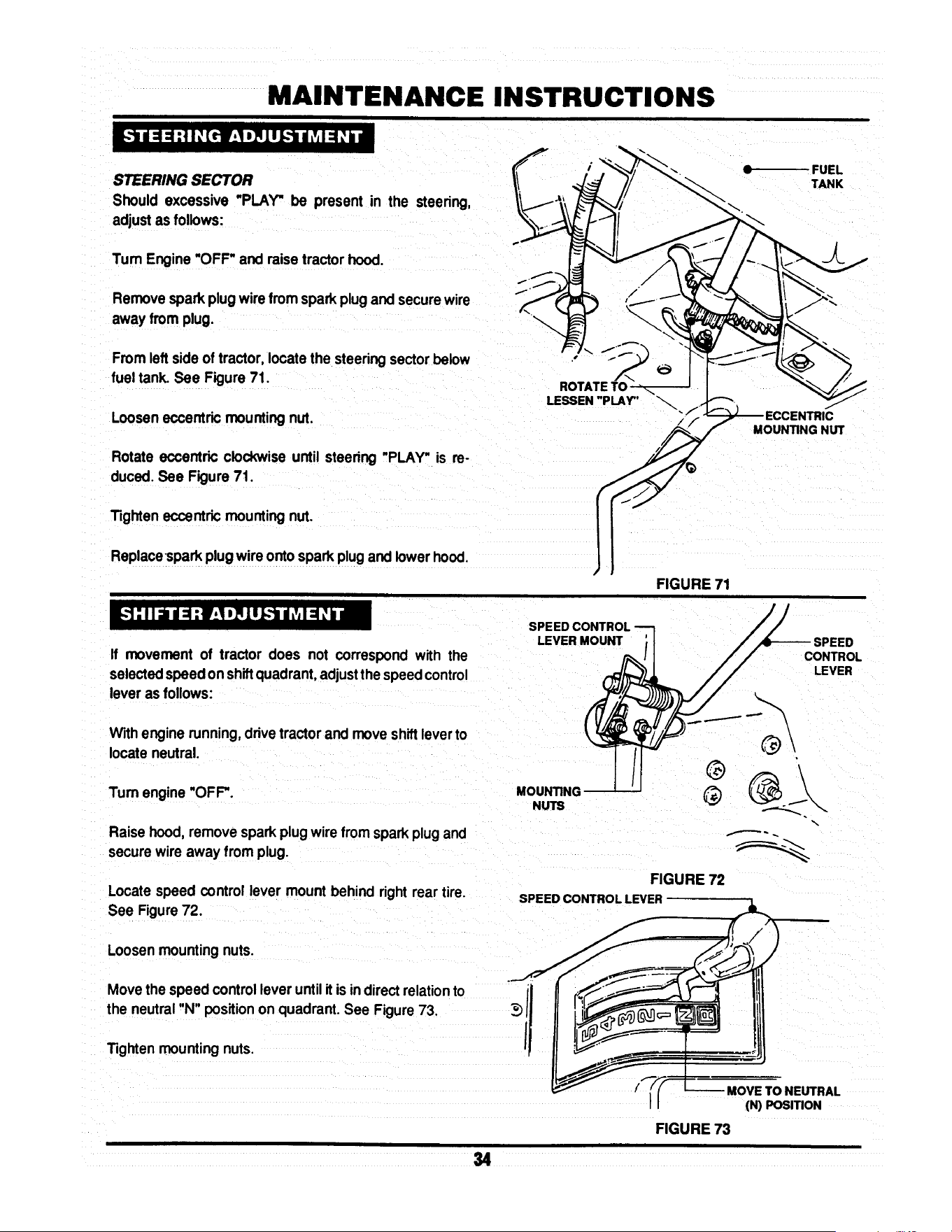
MAINTENANCE INSTRUCTIONS
STEERING SECTOR
Should excessive "PLAY" be present in the steering,
adjustas follows:
Tum Engine"OFF" and raise tractorhood.
Removespark plugwire from spark plug and securewire
away from plug.
From leftside of tractor,locatethe steeringsectorbelow
fuel tank. See Figure 71.
Looseneccentricmounting nut.
Rotate eccentric clockwise until steering "PLAY" is re-
duced.See Figure 71.
Tighteneccentricmounting nut.
Replacespark plugwire onto sparkplugand lowerhood.
FIGURE 71
If movement of tractor does not correspond with the
selectedspeedonshiftquadrant,adjustthe speedcontrol
lever as follows:
Withengine running,drivetractor and move shiftleverto
locateneutral.
Turn engine "OFF".
Raise hood,remove sparkplugwire fromsparkplugand
securewire away from plug.
Locate speed control lever mount behind right rear tire.
See Figure72.
Loosenmountingnuts.
Movethe speed controlleveruntilit is indirectrelationto
the neutral"N"position on quadrant. See Figure 73.
Tighten mounting nuts.
SPEED CONTROL
LEVER MOUNT
ED
CONTROL
LEVER
®
MOUNTING (_
NUTS
FIGURE 72
SPEED CONTROL LEVER
MOVE TO NEUTRAL
(N) POSITION
FIGURE 73
34
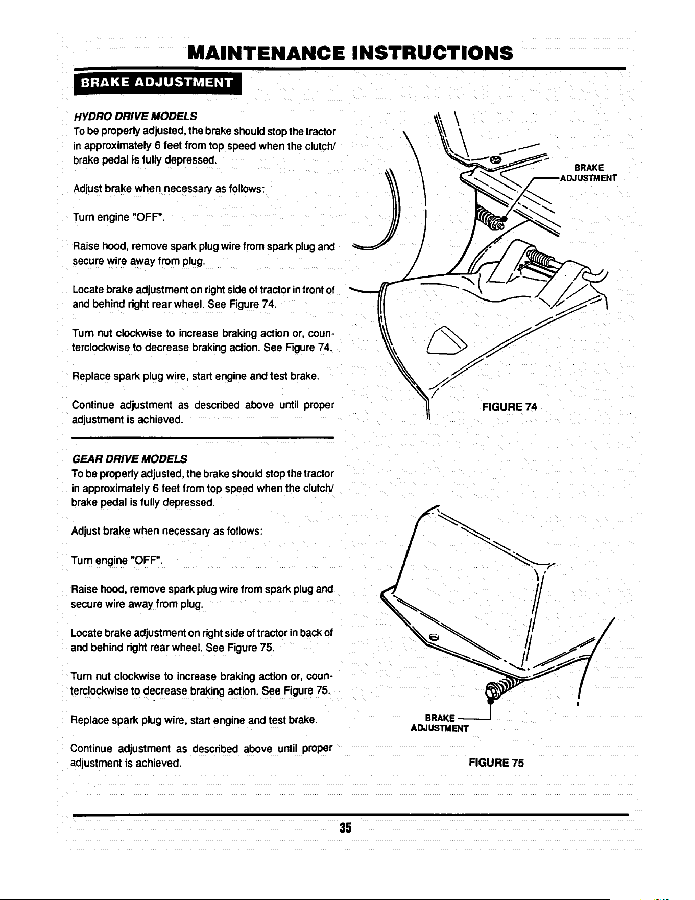
MAINTENANCE INSTRUCTIONS
HYDRO DRIVE MODELS
To be properlyadjusted,the brake shouldstopthe tractor
inapproximately6 feet from top speed when the clutch/
brake pedal is fully depressed.
Adjustbrake when necessary as follows:
Turnengine "OFF'.
Raise hood, remove spark plugwire fromsparkplugand
securewire away from plug.
Locatebrake adjustmenton rightsideoftractor infrontof
andbehind rightrear wheel. See Figure74.
Turn nut clockwise to increase braking action or, coun-
terclockwiseto decrease brakingaction.See Figure 74.
Replace spark plugwire, startengine andtest brake.
Continue adjustment as described above until proper
adjustmentis achieved.
GEAR DRIVE MODELS
Tobe properlyadjusted,the brakeshouldstopthe tractor
inapproximately6 feet fromtop speed when the clutch/
brakepedal is fully depressed.
Adjustbrake when necessaryas follows:
Turn engine "OFF".
Raisehood, remove sparkplugwire from spark plug and
securewire away from plug.
Locatebrake adjustmenton rightsideof tractorin backof
and behind rightrear wheel. See Figure 75.
Turn nut clockwise to increase braking action or, coun-
terclockwiseto decrease brakingaction.See Figure75.
Replace spark plugwire, startengine and test brake.
Continue adjustment as described above until proper
adjustmentis achieved.
\
FIGURE 74
ADJUSTMENT
FIGURE 75
BRAKE
35

ELECTRICAL
Figure 76 illustratestypical hamess mutingon all the
Series D Lawn Tractors. Use this when locatingvarious
electricalcomponents.
_---- O BATI1ERY
NEGATIVE (-)
-TO BATTERY
PosmvF.(+)
TERMINAL
D
(UNDER SEAT)
R,H°
HEADLIGHT
SWITCH
BLADE ENGAGEMENT
LEVER SWITCH
SWITCH
20 AMP-
FUSE
BRAKE
SWITCH
HEADUGHT
HEAD
HARNESS
HARNESS
GROUND
TO ENGINE
FIGURE 76
36

ELECTRICAL
The schematics below, Figure 77 & Figure 78 represent
models with and without headlights.
BRIGGS & STRA TTON WITHOUT LIGHTS
STARTER k
"EDI
/-IGNITION
ENGINE /GROUND
RED
RED
'_--ALTERNATOR
BLACK RED
BATTERY
PEDAL SWITCH
INoj. I
I
I
BLACK
GREENI I N_ I II
I I BLACK
RED
I
B_ YELLOW
BLUE
FIGURE 77
BRIGGS & STRA TTON WITH LIGHTS
ANTI-AFTER FIRE
SOLENOID --_
\
\
ENGINE
STARTER
BLACK
BAI"rlERY
IGNmON GROUND
AC OUTPUT
RED
PINK
RED
ALTERNATOR
RED
SOLENOID
RED
PEDAL
SWITCH
BLACK
PTO
SWITCH
RED
BLACK
BLACK
UGHT
SWITCH
_mTION
KEYswrrc_
YEllOW
SEAT
SWITCH
IN_ I
I" Tl
r
HEAD
UGHTS
SEAT
SWITCH
GREEN
PURPLE
FIGURE 78
37

!
3 YEAR LIMITED WARRANTY
For three (3) years from purchase date for the original purchaser's residential, non-commercial use, SNAPPER, through
any SNAPPER dealer will replace, free of charge (except for taxes where applicable), any part.or parts found upon
examination by the factory at McDonough, Georgia, to be defective in material or workmanship or both.
For ninety (90) days from purchase date for the odginal purchaser's commercial, rental, or other non-residential use
SNAPPER, through any SNAPPER dealer will replace, free of charge, any part or parts found upon examination by th=
factory at McDonough, Georgia, to be defective in material or workmanship or both.
All transportation costs incurred by the purchaser in submitting material to a SNAPPER dealer for replacement under
this warranty must be paid by the purchaser.
This warranty does not apply to engines and their components, hydro transmissions, gear drive transmissions and
batteries, as these items are warranted separately. This warranty does not apply to parts that have been damaged by
accident, alteration, abuse, improper lubrication, normal wear, or other cause beyond the control of SNAPPER. This
warranty does not cover any machine or component part that has been altered or modified changing safety,
performance, or durability.
There is no other express warranty.
DISCLAIMER OF WARRANTY
Implied warranties, including those of merchantability and fitness for a particular purpose, are limited to three
(3) years from purchase date for the original purchaser's residential or other non-commercial use, and ninety
(90) days from purchase for the original purchaser's commercial, rental or other non-residential use, and to the
extent permitted by law, any and all implied warranties are excluded. This is the exclusive remedy. Liabilities
for consequential damages, under any and all warranties are excluded.
Some states do not allow limitations on how long an implied warranty lasts, or do not allow the exclusion or
limitation of incidental or consequential damages, so the above limitation or exclusion may not apply to you.
This warranty gives you specific legal rights, and you may also have other rights which vary from state to state.
WARNING: THE USE OF REPLACEMENT PARTS OTHER THAN GENUINE SNAPPER PARTS MAY IMPAIR THE
SAFETY OF SNAPPER PRODUCTS AND WILL VOID ANY LIABILITY AND WARRANTY BY SNAPPER
ASSOCIATED WITH THE USE OF SUCH PARTS.
IMPORTANT: Please fill outthe attachedSNAPPER Product RegistrationCard immediatelyand mail to:
Snapper's Product Registration Center, P.O. Box 777, McDonough, Georgia 30253

SERVICE NOTES

SERVICE NOTES

Safety Instructions & Operator's Manual for
8NAPPER
LAWN TRA C TOR
HYDROSTA TIC &
GEAR DRIVE
SERIES D
IA WARNING: The engine exhaust from this product contains chemicals known to the State I
of Califomia to cause cancer, birth defects or other reproductive harm.
I
COPYRIGHT © 1998
SNAPPER INC
ALL RIGHTS RESERVED
MANUAL No. 3-5576 (REV. 2, 6/98)

Safety Instructions & Operator's Manual for
,SNAPPER,
LAWN TRA CTOR
HYDROSTATIC &
GEAR DRIVE
SERIES D
MODELS
GEAR DRIVE HYDROSTATIC
DRIVE
LT120G30DB LT140H33DBV
NLT120G30DB LT145H33DBV
LT125G38DB LT145H38DBV
NLT145H38DBV
I
MODEL DESIGNATION
ENGINE HP
DRIVE SYSTEM TYPE
CUTTING WIDTH
MODEL NUMBER EXPLANATION
LT I 145I H 1381 O I B I V I
i ENGINE TYPE
; ENGINE MODEL
SERIES DESIGNATION
LT - Lawn Tractor Model Designation
120 - 12.0 HP Engine Horse Power
125 - 12,5 HP Engine Horse Power
H - Hydrostatic Transmission
30 - 30" Cutting Width Mower
33 - 33" Cuttino Width Mower
140 - 14.0 HP Engine Horse Power
145 - 14.5 HP Engine Horse Power
G - Gear Drive Transmission
38 - 38" Cutting Width Mower
D - Series Designation
B - Briggs & Stratton Engine
V - Over Head Valve Type Engine
Thank you for buying a SNAPPER product! Before operating the Lawn Tractor, read and follow the
"IMPORTANT SAFETY INSTRUCTIONS" on pages 2 & 2A, all other instructions contained in this manual and
the accompanying booklet "About Power Mower Safety". "Lawn mowers and all power equipment can be
potentially dangerous ff used improperly. REMEMBER: SAFETY REQUIRES CAREFULL USE IN ACCORDANCE
WITH INSTRUCTIONS AND COMMON SENSE/.
COPYRIGHT © 1998
SNAPPER NC
ALL RIGHTS RESERVED
MANUAL No. 3-5576 (REV. 2, 6/98)

IMPORTANT SAFETY INSTRUCTIONS
WARNING: This powerful cutting machine is capable of amputating hands and feet and can throw objects that
can cause injury and damage! Failure to comply with the following SAFETY instructions could result in
serious injury or death to the operator or other persons. The owner of the machine must understand these
instructions and must allow only persons who understand these instructions to operate machine. Each
person operating the machine must be of sound mind and body and must not be under the influence of any
substance which might impair vision, dexterity or judgment. If you have any questions pertaining to your
machine which your dealer cannot answer to your satisfaction, call or write the Customer Service Department
at SNAPPER, McDonough, Georgia 30253. Phone: (1-800-935-2967).
PROTECTION FOR CHILDREN
Tragic accidents can occur if the operator is not alert
to the presence of children. Children are often
attracted to the machine and the mowing activity.
Never assume that children will remain where you
last saw them.
1. KEEP children out of the mowing area and under
the watchful care of a responsible adult.
2. DO NOT allow children in yard when machine is
operated (even with the blade OFF).
3. DO NOT allow children or other passengers to
ride on machine or on attachments (even with the
blade OFF). They may fall and be seriously
injured.
4. DO NOT allow pre-teenage children to operate
machine.
5. ALLOW only responsible adults & teenagers with
mature judgment under close adult supervision to
operate machine.
6. BE SURE the area is clear of others before
mowing and turn machine OFF if anyone enters
the area.
7. DO NOT mow in reverse unless absolutely
necessary. LOOK BEHIND and down for small
children before and when backing.
8. USE EXTRA CARE when approaching blind
corners, shrubs, trees, or other objects that may
obscure vision.
PROTECTION AGAINST TIPOVERS
Slopes are a major factor related to loss-of-control
and tip-over accidents, which can result in severe
injury or death. All slopes require extra CAUTION. If
you cannot back up the slope or if you feel uneasy on
it, DO NOT mow it. Use extra care with grass catchers
or other attachments; these can change the stability
of the machine.
1. DO NOT operate machine on slopes exceeding 15
degrees (27% grade).
2. Exercise EXTREME CAUTION on slopes above 10
degrees (18% grade). Turn blade OFF when
traveling uphill. Use first speed and avoid sudden
or sharp turns.
3. DO NOT mow back and forth across face of
slopes. Mow up and down.
PROTECTION AGAINST TIPOVERS
(Continued From Previous Column)
4. AVOID uphill starts. If machine stops going uphill
or tires lose traction, turn blade OFF and back
slowly down the slope.
5. STAY ALERT for holes and other hidden hazards.
Tall grass can hide obstacles. Keep away from
ditches, washouts, culverts, fences and
protruding objects.
6. KEEP A SAFE DISTANCE (at least 3 feet) away
from edge of ditches and other drop offs. The
mower could turn over if an edge caves in.
7. Always begin forward motion in the #1 speed
position.
8. Use weights or a weighted load carrier in
accordance with instructions with a grass catcher
on slopes above 10 degrees (18% grade).
9. DO NOT put your foot on the ground to try to
stabilize the machine.
10. DO NOT mow on wet grass. Reduced traction
could cause sliding.
11. DO NOT mow under any condition where traction,
steering or stability is doubtful without first test
driving over the terrain with blade OFF.
PREPARATION
1. Read this manual, get to know where all controls
are located and practice how to use them before
starting for the first time, and at the beginning of
each season. Read and follow Warnings and
Instructions on engine and machine. Read and
follow operator's manual and instructions
furnished with attachments.
2. Only mature, responsible persons shall operate
the machine and only after proper instruction.
3. Handle fuel with extra care. Fuels are flammable
and vapors are explosive. Use only an approved
fuel container. Never remove fuel cap or add fuel
with engine running. Add fuel outdoors only with
engine stopped and cool. Clean spilled fuel from
machine. DO NOT smoke.
4. Practice operation of machine with BLADE OFF to
learn controls and develop skills.
(Continued on Next Page}

IMPORTANT SAFETY INSTRUCTIONS
PREPARATION
(Continued From Previous Page)
5. Check the area to be mowed and remove all
objects such as toys, wire, rocks, limbs and other
objects that could cause injury if thrown by blade
or interfere with mowing.
6. Keep people and pets a safe distance from
machine.
7. Check shields, deflectors, switches, blade
controls and other safety devices frequently for
proper operation and location.
8. Make sure all safety decals are clearly legible.
Replace if damaged.
9. Protect yourself when mowing and wear safety
glasses, long pants and substantial footwear.
10. Know how to STOP blade and engine quickly in
preparation for emergencies.
11. Use extra care when loading or unloading the
machine into a trailer or truck.
12. Check grass catcher components frequently for
signs of wear or deterioration and replace as
needed to prevent injury from thrown objects
going through weak or worn spots.
OPERATION
1. Mount and dismount machine from left side.
2. Start engine from operator's seat, if possible.
Make sure blade is OFF and parking brake is set.
3. STOP blade, STOP engine, set parking brake and
remove key when leaving machine.
4. DO NOT operate machine unless properly seated
with feet on feet rests or pedal(s).
5. STOP BLADE and ENGINE and make sure blade
has stopped before removing grass catcher or
unclogging mower to prevent loss of fingers or
hand.
6. Blade must be OFF except when cutting grass.
Set blade in highest position when mowing over
rough ground.
7. Keep hands and feet away from rotating blade
underneath deck. NEVER place foot on ground
while BLADE is ON or machine is in motion.
8. Deflector or entire grass catcher must be in place.
NEVER point discharge at people, passing cars,
windows or doors.
9, Slow down before turning.
MAINTENANCE
1. Never store machine or fuel container inside
where fumes may reach an open flame, spark or
pilot light such as in a water heater, furnace,
clothes dryer or other gas appliance. Allow
engine to cool before storing machine in an
enclosure. Store fuel container out of the reach of
children in a well ventilated, unoccupied building.
2. Keep engine free of grass, leaves or excess
grease to reduce fire hazard and engine
overheating.
3. When draining fuel tank, drain fuel into an
approved container outdoors and away from open
flame.
4. Check brakes frequently; adjust, repair or replace
as needed.
5. Keep all bolts, nuts and screws properly tight.
Check that all cotter pins are in proper position.
6. Always provide adequate ventilation when
running engine indoors. Exhaust gases contain
carbon monoxide, an odorless and deadly
poison.
7. Disconnect negative (black) cable from battery
before performing maintenance or service.
Cranking engine could cause injury.
8. Never work under machine without safety blocks.
9. Service engine and make adjustments only when
engine is stopped. Remove spark plug wire(s)
from spark plug(s) and secure wire(s) away from
spark plug(s).
10. DO NOT change engine governor speed settings
or overspeed engine.
11. Lubricate machine at intervals specified in
manual to prevent controls from binding.
12. Mower blades are sharp and can cut. Wrap the
blades or wear heavy leather gloves and use
CAUTION when handling them.
13. NEVER test for spark by grounding spark plug
next to spark plug hole; spark plug could ignite
gas exiting engine.
14. Have machine serviced by an authorized
SNAPPER dealer at least once a year and have the
dealer install any new safety devices.
15. Use only genuine SNAPPER replacement parts to
assure that original standards are maintained.
10. Watch out for traffic when near or crossing
roadways.
11. STOP engine immediately after striking an
obstruction. Inspect machine and repair damage
before resuming operation.
12. Mow only in daylight or with good artificial light.
13. Move joystick (if equipped) SLOWLY to maintain
control during speed and directional changes.
14. Exercise CAUTION when pulling loads. Limit
loads to those you can safely control and attach
loads to hitch plate as specified with SNAPPER
attachment instructions.
2A
TABLE OF CONTENTS
IMPORTANT SAFETY INSTRUCTIONS ...... 2 & 2A
TABLE OF CONTENTS ........................................ 3
FAMILIARIZATION ............................................. 4-5
Serial & Model Number Location ........................... 4
Controls .................................................................... 5
Components ........................................................... 5
OPERATING INSTRUCTIONS ........................ 6-11
Pre-start Checklist ................................................... 6
Adjusting Operator's Seat ....................................... 6
Starting & Stopping Engine ....................................... 7
Starting & Stopping Wheel Drive ............................... 8
Setting & Releasing Parking Brake ..........................
Starting & Stopping Mower Blades .......................... 9
Adjusting Cutting Height ......................................... 10
Raising Chute Deflector ......................................... 10
Rolling Tractor W_h Engine Off ......................... 9-10
Tips on Mowing ....................................................... 11
ACCESSORIES .................................................. 11
TROUBLESHOOTING GUIDE ....................... 12-13
MAINTENANCE INSTRUCTIONS ................. 14-35
Service Schedule ......................................... 14
Maintenance Parts ....................................... 14
Hydrostatic Transmission Oil .................... 15
To CheckOilLevel...............................................
Changing Engine Oil ................................... 16
Lubrication (Tractor] .............................. 17-18
Front Wheel Bearings ......................................... 17
Axle Spindles ....................................................... 17
Steering Shaft ...................................................... 17
Clutch/Brake Pivot............................................... 17
Steering Sector Gear .......................................... 17
Steering Drag Link .............................................. 18
Steering Tie Rod ................................................. 18
Park Brake Latch ................................................ 18
Deck Lift Mechanism .......................................... 18
Blade Engagement Mechanism ......................... 18
Engine Service ............................................. 19
Engine Air Pre-Cleaner ....................................... 19
Engine Air Cleaner .............................................. 19
Spark Plug ........................................................... 19
Fuel Filter ........................................................... 19
Engine Cooling System ...................................... 20
MAINTENANCE INSTRUCTIONS (Continued)
Battery Service ............................................. 20-21
Battery Electrolyte Check ............................ 20
Battery Charging ................................................ 21
Mower Deck Removal/Reinstallation .......... 22-23
Standard Mower Blade Service ................... 26-28
Standard Blade Wear Limits ....................... 26
Blade Removal/Replacement ...................... 26-27
33" Mower Blade ............................................ 26
38" Mower Blade ............................................ 27
Sharpening Standard Blade(s) ................ 28
Ninja Mower Blade Service .................................. 28
Ninja Blade Wear Limits................................28
Ninja Blade Sharpening .................................29
Belt Service .................................................. 21-25
Mower Drive Belt Removal/Replacement 25
33" & 38" Deck Drive Belt.............................25
Traction Drive Belt Service .................... 21-24
Traction Drive Belt Removal ......................... 23
Traction Drive Belt Replacement .................. 24
Traction Drive Belt Adjustment ................ 29-30
Deck Level Adjustment .............................. 31-33B
Side to Side Level ............ 31-32 & 33A-33B
Front to Rear Level ........................32-33 & 33B
Sector Plates..................................................32
FrontLiftRod ......................................33 & 33A
Shifter Adj ustment ............................................ 34
Steering Adjustment ......................................... 34
Wheel Brake Adjustment .................................. 35
ELECTRICAL SYSTEM ................................. 36-37
Wiring Harness Routing ...................................... 36
DIAGRAMS, Briggs Engine w/o lights................ 37
DIAGRAMS, Briggs Engine w/lights ................... 37
WARRANTY ....................................................... 38
PRIMARY MAINTENANCE ............................ 39-42
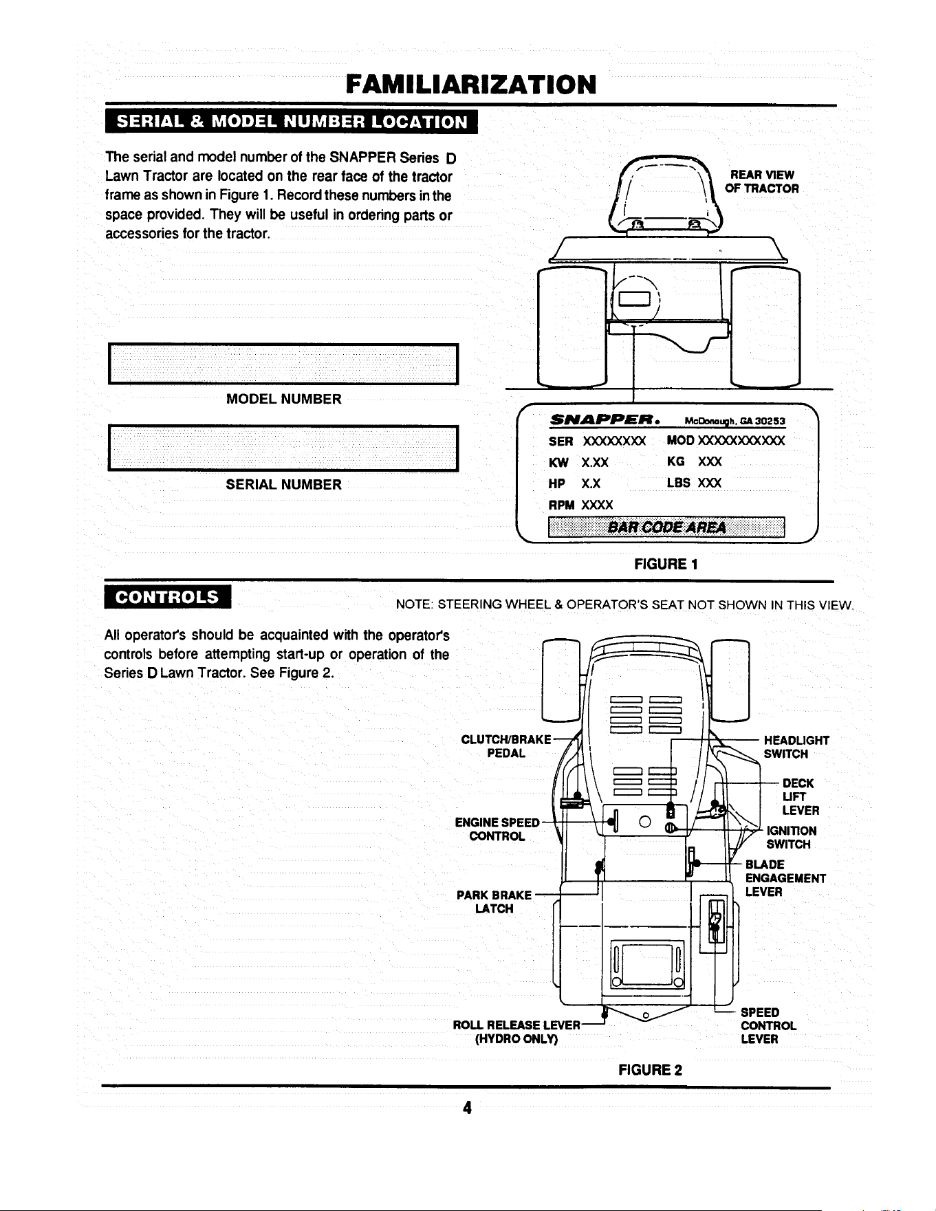
FAMILIARIZATION
H_.'t::1:! P"_IHE:I _v,(o] _] ::!mid_Ill Lv,I :1:1:1 Ko]).]P',_In/ (o]; •
The serial and model number of the SNAPPER Series D
Lawn Tractor are located on the rear face of the tractor
frame as shown in Figure 1. Record these numbers inthe
space provided. They will be useful in ordering parts or
accessories for the tractor.
!
MODEL NUMBER
SERIAL NUMBER
I
REAR VIEW
_/. !_OF _ACTOR
/ \
/
SNAPPER. McOn.p. = 3o2ss
SER XXXXXXXX MOD XXXXXXXXXXX
KW X.XX KG XXX
HP X.X LBS XXX
RPM XXXX
_iiiii_ii_ii_iiiiiii_}iiii_ii!i!_!iii_i_!__e_n_iii!i!i!i_iii!_!i!iiii_!_i_ii_i!_i_i_!
FIGURE 1
m[o{o]: ind:To] _!
NOTE: STEERING WH EEL & OPERATOR'S SEAT NOT SHOWN IN THIS VIEW.
All operator'sshould be acquaintedwith the operator's
controlsbefore attemptingstart-up or operationof the
SeriesD LawnTractor.See Figure2.
PEDAL
ENGINE SP
CONTROL
PARK BRAKE
LATCH
(HYDRO ONLY)
__W HEADLIGHT
ITCH
DECK
UFT
.°v°.
IGNITION
I_J/ SWITCH
-_ BLADE
! E_G_RGEMENT
SPEED
CONTROL
LEVER
FIGURE 2
4

FAMILIARIZATION
[_o] Lv,I ".,To]_,1:1_,b u_
The nomenclature drawings, Figures 2 & 3, illustrate the
essential components of the SNAPPER Series D Lawn
Tractor. It is recommended that all operators of this
equipment become thoroughly familiar with the compo-
nents and their operation BEFORE OPERATING. Spe-
cific details involving the engine are found in the separate
Engine Owners' Manual. Study the Important Safety
Instructions, this Operators' Manual and Engine Owners'
Manual before operating this machine. Keep these
manuals avail able for future reference.
SEAT
ADJUSTMENT
KNOB
BATTERY
(UNOER SEAR
---OPERATOR'S
SEAT
FAST_i
SLOW-_
ENGINE-_-_
SPEED
CONTROL
_ CHOKE
!
/
WHEEL /
/
.DASHBOARD
CONTROLS
FUEL TANK
(UNDER HOOD)
CHUTE
DEFLECTOR
HEADUGHTS
MOWING DECK
(33" SHOWN)
ENGINE
FIGURE 3

OPERATING INSTRUCTIONS
I d :! =5.'t if:! :_iI It.,].-I :(H ;I ii [..1,i
Make the followingchecks and perform serviceas re-
quiredbeforeeach start-up.
Checktires and add air as needed to bringpressure to
12psi in fronttires and 10 psi in reartires. If guardsare
missingor damaged, Replace BEFORE usingmower.
Checkguards,deflectorsand coversto makesure all are
inplaceand securelytightened.
Checkengineoil.Addoil as neededtobringup to, but not
over,thefullmark.Refertothe engineowner'smanualfor
oil specifications.
Checkoperator'sseat adjustment.Adjustas necessary.
Check blade engagement lever to insure it operates
properly.The blade engagement lever must be moved
manuallyfrom "ON" to "OFF"to stop blade.
TANK
/
CAP
_.AFTER FILLING
TANK
Clean exteriorsurfacesof cuttingdeck,engineandtractor
from any accumulation of grass clippingsand debris.
Keepengineair intake screensandcoolingfinscleanatall
times.
Withengine "OFF"move the tractoroutsideand addfuel
to the fuel tank. Securely tightenfuel cap after refueling.
See Figure 4. Refer to engine owner's manual for fuel
specifications.
FIGURE 4
FRONT TO REAR ADJUSTMENT
With engine"OFF", raise operator'sseat and loosenthe
two adjustingknobs onthe seat support.See Figure5.
Lowerthe seat.
LOOSEN ADJUSTING
KNOBS TO ADJUST SEAT
Sit in the operator's seat and slide the seat forward or
backward until the clutch/brakepedal can be fully de-
pressedcomfortably.
Raiseseatandtightenthe adjustingknobstosecureseat
inposition.
6
FIGURE 5
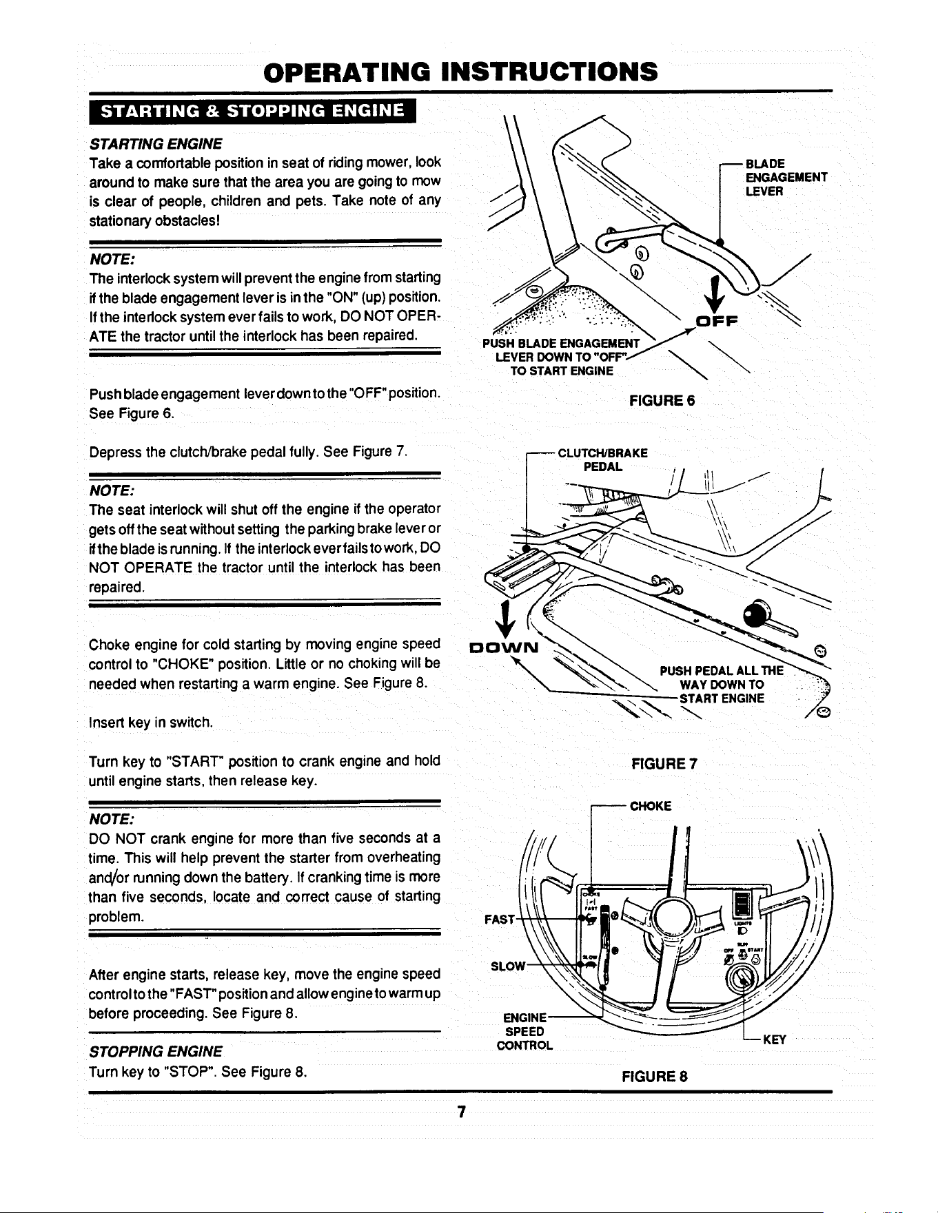
OPERATING INSTRUCTIONS
:,In#,I :_idI: [rl:_..'t liD] "J"JI: [tl =1_[r] I: I =i
I _
STARTING ENGINE
Take a comfortablepositionin seat of ridingmower,look
aroundto make surethat the area you are goingto mow
is clear of people, children and pets. Take note of any
stationaryobstacles!
NOTE:
The interlocksystemwillpreventthe engine from starting
ifthe blade engagementleveris in the "ON" (up)position.
If the interlocksystemeverfails to work, DO NOT OPER-
ATE the tractoruntilthe interlockhas been repaired.
Pushblade engagement leverdowntothe "OFF"position.
See Figure6.
ENGAGEMENT
LEVER
PUSH BLADE ENGAGEMENT
TO START ENGINE
\
\
FIGURE 6
Depress the clutch/brakepedal fully. See Figure7.
NOTE:
The seat interlockwill shut off the engine ifthe operator
gets offthe seat withoutsetting the parkingbrakeleveror
ifthe bladeis running.If the interlockeverfailstowork,DO
NOT OPERATE the tractoruntil the interlockhas been
repaired.
Choke enginefor cold startingby moving engine speed DOWN
controlto "CHOKE" position. Littleor no chokingwill be '_',X _
needed when restarting a warm engine. See Figure 8.
\
Insert key inswitch.
L
Turn key to "START" position to crank engine and hold
until engine starts, then release key.
NOTE:
DO NOT crank engine for more than five secondsat a
time. This will help prevent the starterfrom overheating
an_or runningdownthe battery. Ifcrankingtime is more
than five seconds, locate and correct cause of starting
problem.
After engine starts,release key, move the engine speed
controlto the "FAST" positionandallow enginetowarmup
before proceeding.See Figure8.
STOPPING ENGINE
Turn key to "STOP". See Figure8.
FIGURE 7
CHOKE
ENGINE -_-_-._ _. _--- _--_,,_
LKEy
FIGURE 8

OPERATING INSTRUCTIONS
_._ net :_unlI: [_lr:l-_ n[o]"J"JI _[riYl: 1:1=1nl ,] ;1Lvi=
STARTING WHEEL DRIVE OF HYDRO MODELS
Shift speed controllever to neutral.
Start engine.
Release brake pedal.
Slowlyshiftspeed controlleverforwardfor forwardmotion
or to the rear for reverse motion.See Figure9.
STOPPING WHEEL DRIVE
Fully depress clutch/brake pedal to stop wheel drive.
Shift speed control lever to neutral. See Figure 10.
NOTE: (HYDRO DRIVE MODELS ONLY)
When the tractor is moving forward and the clutch/brake
pedal is pushed all the way down, the speed control
handlewillautomaticallyreturnto approximately1/3offull
forward speed. Move handle to desired positionafter
releasing brake pedal.
STARTING WHEEL DRIVE OF GEAR MODELS
Shiftspeed controlleverto neutral.
Start engine.
Fullydepressclutch/brakepedal.
Move speed controlhandle forward to Firstspeed.
See Figure 11.
Slowly release clutch/brakepedal to begin motion.
FORWARD
SPEEDS
CLUTCH/BRAKE
PEDAL
SPEED CONTROL
HANDLE
HANDLE
REVERSE
I
FIGURE 9
CLUTCH/BRAKE
PEDAL TO STOP
WHEEL MOTION
FIGURE 10
NOTE: (GEAR DRIVE MODELS ONLY)
The clutch/brake pedal must be fully depressed when
changingspeed.
FORWARD
SPEEDS
REVERSE
NEUTRAL
FIGURE 11
8
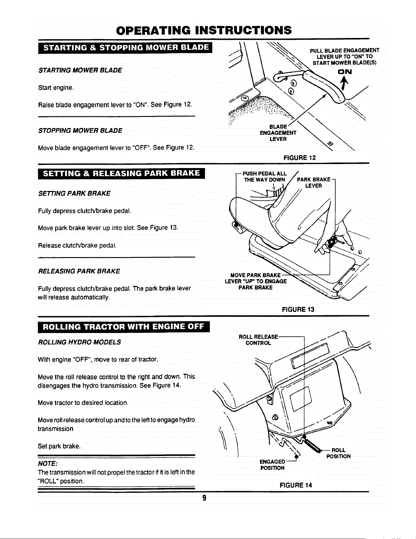
OPERATING INSTRUCTIONS
_-'lmmr.1:_mnlI _[rt::lE._m go] ..J..JI _[it L',[olV,'J=1:l :| mF_,lp]=l
STARTING MOWER BLADE
Start engine.
PULL BLADE ENGAGEMENT
LEVER UP TO "ON" TO
START MOWER BLADE(S)
ON
Raise blade engagement leverto "ON". See Figure 12.
STOPPING MOWER BLADE
Move blade engagement leverto "OFF". See Figure 12.
I_-.1:a / dI ,_[rl:Ji :t :1al:f.!,.-] I _'[rll ".,/:I:t [1:1 ::El [4::1
SETTING PARK BRAKE
ENGAGEMENT
LEVER
FIGURE 12
PEDALALL
PARK BRAKE
LEVER
Fullydepress clutch/brake pedal.
Movepark brake lever up into slot. See Figure 13.
Release clutch/brake pedal.
RELEASING PARK BRAKE
Fully depress clutch/brake pedal. The park brake lever
will release automatically.
MOVE PARK
LEVER"UP"TOENGAGE
PARK BRAKE
FIGURE 13
I :{o] ! q I _[ttl /; f-Till I[Ol:llV,'| 1111:I =1_[d I _I ::l[o]d =1
ROLLING HYDRO MODELS
ROLL RELEASE --
CONTROL
With engine "OFF", move to rearof tractor.
Movethe roll release control to the right and down. This
disengages the hydro transmission. See Figure 14.
Move tractorto desired location.
Moveroll release controlupandtothe leftto engage hydro
transmission
Set park brake.
NOTE:
The transmission will not propel the tractor if it is left in the
"ROLL" position.
\
\
\
ENGAGED
POSITION
FIGURE 14
POSITION

OPERATING INSTRUCTIONS
ROLLING GEAR DRIVE MODELS GEARDRIVEMODELSHOWN
With engine 'OFF', fullydepressclutcl_/brakepedal.
Place speed controllever in the neutral(N) position.See
Figure 15.
Release clutch/brakepedal and movetractorto desired
location.
Setparkbrakeandplacespeedcontrolleverintoaforward
speed.
m:_,_[_1I: [rl_]: t,J=i =1,]=1il _=[,, lo_ia=
/
FIGURE 15
1997 MODEL YEAR SHOWN
-SPEED
CONTROL
HANDLE
RAISING CHUTE DEFLECTOR for CLEARANCE
THROUGH GATES or TRANSPORTS
Remove wing nuts and flat washers, securing chute
deflector to deck. See Figure 16.
Raise chute deflector and reinstall flat washers and wmg
nuts onto studs to prevent loss.
Transport tractor to desired location.
Never attempt to operate mower without chute
deflector secured In the down position.
WING NUT
_,,._ FLAT WASHER
CHUTE DEFLECTOR
MUST BE IN THE "'DOWN"
POSITION BEFORE
OPERATING MOWER
FIGURE 16
i]I o_LuZ,,._dI _(_ub • dI _(_: I _ [_: b •
ADJUST CUTTING HEIGHT for all DECKS
Depresslock button on deck liftlever. See Figure17.
Raiseor lower deck to anyof six positions as desired.
DEPRESS LOCK ---I
( 15.I.oPO::_ON__s,
CUT
FIGURE 17
10

OPERATING INSTRUCTIONS
I / I ",.Z.."_l] _I ;l [*;'i'l I _[rII
For best results,use the followingtips when mowing.
When mowing,cutonly 1/3 of grassheight.Cuttinggrass
deeper couldbe harmfulto your lawn.
If cuttingextremelytall grass, make one cuttingwith the
deck in its highestcuttingposition,then lower deck to
desiredposition and a second cut.
Mow when lawnis dry.
Mow often.Shortergrassclippingsdecomposequicker.
Keep mower blades sharp. A dull blade tearsand shreds
grass instead of cutting. Your SNAPPER dealer can
sharpen blades as required.
Alternate mowing pattern to reduce the possibility of grass
matting.
Mow withenginespeed controlinthe "FAST" positionand
speed controlhandlein a "SLOW" position.
Clean deck, removing all grass clippingsanddebris from
the top and undersideof deck after each use.
V'_ltl'_1!W_.!:] il =f;_*-[*4 =b'_._*]:! I $1
The SNAPPER Series D LAWN TRACTOR can be equipped with a variety of accessories that increase its versatility.
The accessories available for each model are listed in the chart below. Contact an authorized SNAPPER dealer for
ordering any of the accessories desired.
AVAILABLE
ACCESSORIES
Thatcherizer
Dethatcher
Lawn SweeperDethatcher
Lawn Sweeper
Aerator
Broadcast Spreader
Lawn Roller
Snow Blade*
46" DozerBlade SpringTrip****
Dozer Blade Support Kit
2-Stage Snow Thrower**
38" Snow Thrower....
Snow Thrower Support Kit
OPPLT Debris Blower****
Hitch/Subframe Kit
Weight Kit
Tire Chains
Ninja Recycling/Mulch Kit
38 Ninja Recycling/Mulch Kit
38 Wave Recycling/Mulch Kit
Single Bag Catcher***
38" Single Bag Catcher
Dump Cart
Twin Bag Catcher......
38" Twin Bag catcher
Adapter Mounting Kit
Gage Wheel Kit
Utility Trailer
Bag-N-Wagon
Bag-N-Wagon Hitch Kit
LT120G30DB
6-1247
6-1912
6-1914
6-1913
6-1911
6-1916
6-1915
NA
6-1881
NA
NA
6-1880
NA
6-1883
6-1879
NA
NA
6-1254
NA
NA
6-0942
NA
6-0697
NA
NA
6-1334
6-1157
6-1910
NA
NA
NLT120G30DB
6-1247
6-1912
6-1914
6-1913
6-1911
6-1916
6-1915
NA
6-1881
NA
NA
6-1880
NA
6-1883
6-1879
NA
NA
6-1254
NA
NA
6-0942
NA
6-0697
NA
NA
6-1334
6-1910
NA
NA
LT125G38DB
6-1247
6-1912
6-1914
6-1913
6-1911
6-1916
6-1915
NA
6-1881
NA
NA
6-1880
NA
6-1883
6-1879
NA
NA
NA
6-1878
6-1877
6-1886
6-1886
6-0697
NA
6-1888
6-1334
NA
6-1910
NA
NA
LT140H33DBV
LT145H33DBV
6-1247
6-1912
6-1914
6-1913
6-1911
6-1916
6-1915
6-1352
6-1881
6-1370
8-0560
6-1880
6-1371
6-1883
6-1879
6-1245
6-1085
6-1255
NA
NA
6-0943
NA
6-0697
6-0946
NA
6-1334
NA
6-1910
6-0947
6-1308
* Requires Dozer Blade Su;_port Kit .......... ***Requires Adapter Mounting Kit
** Requires Snow Thrower Support Kit ...... ****Requires Hitch/Subframe Kit
11
LT145H38DBV
6-1247
6-1912
6-1914
6-1913
6-1911
6-1916
6-1915
6-1352
6-1881
6-1370
8-0560
6-1880
6-1371
6-1883
6-1879
6-1245
6-1085
NA
6-1878
6-1877
NA
6-1886
6-0697
NA
6-1888
6-1334
NA
6-1910
NA
NA
NLT145H38DBV
6-1247
6-1912
6-1914
6-1913
6-1911
6-1916
6-1915
6-1352
6-1881
6-1370
8-0560
6-1880
6-1371
6-1883
6-1879
6-1245
6-1085
NA
6-1878
6-1877
NA
6-1886
6-0697
NA
6-1888
6-1334
NA
6-1910
NA
NA

TROUBLESHOOTING
STARTER WiLL NOT
CRANK ENGINE
ENGINE WILL NOT START
1.Battery dead. 1. Service battery.
2. Blown fuse. 2. Replace fuse.
3. Electrical connections loose or corroded. 3. Clean end check connections for good
contact..
4. Defective ignition switch. 4. Contact authonzed SNAPPER dealer.
1. Blade engagement lever in the "ON" position.
I 2. Park brake not set.
3. Fuel tank empty.
4. Engine needs choking.
! 5. Spark plug wire disconnected.
6. Battery weak or dead
7. Faulty intedock switch.
1. Operator not in seat.
2. Engine speed controlinthe "CHOKE" position.
3. Fuel tank empty.
4. Engine air pra-deaner and orair cleaner dirty.
5. Spark plug defective or gap set improperly.
6: Fuel filterstoppedup.
7. Water, debds or stale fuel in fuel system.
1. Excessive load onengine.
2. Engine air pre-deaner or air cleaner dirty.
3. Engineoil level low.
4. Enginecoolingfins end air screens excessivelydirty.
5. Spark plug faulty.
6. Water, debds or stale fuel in fuel system.
ENGINE STALLS AFTER
RUNNING
I
1. Move blade engagement lever to "OFF"
2. Set park brake.
3. Fill fuel tank with fresh fuel.
4. Move engine speed control to "CHOKE"
5. Place spark plug wire onto spark plug.
6. Service battery.
ENGINE LOSES POWER
ENGINE BACKFIRES WHEN
IGNITION KEY TURNED TO
"STOP"
EXCESSIVE VIBRATION 1. Damaged or bent mower blades.
2. Loose blade components.
3. Loose or missing air lift (if equipped).
TRACTOR WILL NOT MOVE
OR LOSS OF TRACTION
3. Low transmissionoil level. (Hydro modelsonly)
4. Shifter out of adjustment.
5. Traction ddve belt requiresadjustment.
6. Traction ddve beltrequires replacement.
7. Contact authorized SNAPPER dealer.
1. Sit in operator's seat.
2. Move engine speed control to "FAST"
3. Refill fuel tank with fresh fue!.
14. Clean or replace filters.
5. Service spark plug.
6. Replace fuel filter.
7. Drain and clean fuel system.
t. Lessen load.
2. Clean or replace filters.
3. Fill with engine oil to proper level.
4. Clean free of all debns.
5. Service spark plug.
6. Drain and clean fuel system.
1. Engine speed control set too "FAST". 1. Set engine speed control to "SLOW" and
allow engine to idle. Then, turn key to "OFF".
1. Service mower blede(s).
2. Service and tighten loose parts.
3. Replace airlifts. Tighten to proper torque.
.Speed control handle in the neutral "N" position. 1. Place speed control in desired speed,
2. Roll release control in "ROLL" Positio n . 2. Move roll release control to the engaged
(Hydro Models Only) position.
3. Bdng oil to proper level.
4. Adjust shifter.
5. Adjust _'action drive belt.
6. Replace tractiondrive belt.
12

TROUBLESHOOTING
BLADE(S) NOT
CUllING
CUTTING GRASS 1.
IMPROPERLY
2.
3.
4.
5.
6.
7,
8.
POOR GRASS 1.
DISCHARGE
1.Blade engagement lever in the "OFF" position.
2, Blade belt requiresadjustment.
3. Blade belt requiresreplacement.
Uneven tire pressure.
Cuing height too low or high.
Engine speed too slow.
Forward speed too fast.
Deck side to side level requires adjustment.
Deck front to rear level requires adjustment.
Blade belt requires adjustment.
Blade belt requires replacement.
Engine speed too slow.
2. Forward speed too fast.
3. Grass is wet.
4 Excessively worn or damaged blade(s).
5. Build-up of grass clippings and debns under deck.
6. Improper blade(s) installed on deck.
7. Blade(s) installed improperly on deck.
BATTERY WILL NOT 1. Poor cable connections.
CHARGE
2. Bad battery cell(s).
OIL LEAKING
FROM TRANSMISSION
1. Move leverto the "ON"position.
2. Adjust mower belt.
3. Replace mowerbelt.
1. Bring to proper pressure.
2. Adjust cuttingheight.
3. Move engine speed oontrol to "FAST'.
4. Move speed controlto a slowerspeed.
5. Adjust side to side level.
6. Adjustfront to rear level.
7. Adjustblade belt tension.
8, Replace blade belt.
1. Move engine speed oontrol to "FAST".
2 Move speed control to a slower speed.
3. Mow when grassis dry.
4.Servicemower blade(s).
5.Cleandeck.
6.InstallproperSNAPPER blades.
7.Installbladesproperly,
I.Cean cablesand batteryterminals.
2. Replace with new battery.
3. Faulty alternator. 3. Contact engine manufacturer's dealer.
1. Loose or missing oil filler cap. (Hydro Models Only) 1. Check oil level and replace oil cap.
2. Leaking axle seals. 2. Contact authorized SNAPPER dealer.
3. Leaking at casing seal 3. Contact authorized SNAPPER dealer.
13

MAINTENANCE INSTRUCTIONS
SUBJECT
Engine
Engine
Engine
Air Pre-Cleaner
Air Cleaner
Spark Plug
Fuel Filter
Engine Cooling
System
Battery
Tires
Drive Belts
Mower Blades
Mower Deck
Mower
Deck
Lubrication
Points
Hydrostatic
Trans. Oil
SERVICE
TO BE PERFORMED
Check Oil Level
Initial Oil Change
Periodic Oil Change
Service Sponge Pre-
Cleaner Element
Replace Element
Replace Plugs
Replace Filter
Clean Shrouds & Fins
Check Electrolyte
Charge Battery
Check Pressures
Check For Wear And
Tension
Check For Wear And
Damage
Clean Debris
Accumulation
Clean Outside and
Underside
Grease or Oil
Check Oil Level
REFERENCE EACH 5 25 50 100 EACH
PAGES USE HOURS HOURS HOURS HOURS SEASON
Page 6 X
Pages 15 & 16 X
page 15 X*
Engine Manual X**
&Page 19
Engine X**
Manual.
Engine X
Manual.
Page 19 X
Engine Manual X**
& Page 20
Page 20 X X
Page 20 & 21 X
Page 6 X X
Pages 22-26 X X
Pages 20-21 X
i
Page 6 X X X
Page 6 X X X
Pages 17 &:18 X X
Page 15 X
*Change oil every 25 hours when operating under heavy load or high temperatures.
**Clean more often under dusty conditions or when air debris is present
TRACTOR
MODEL No.
LT120G30DB, NLT120G30DB
LTI25G33DB
LT140H33DBV, LT145H33DBV
LT125G38DB
LT145H38DBV, NLT145H38DBV
DRIVE BELTS
Engine to Transmission Engine to Deck Standard
2-8585 2-8793 1-8069
2-8585 2-9205 3-4168
2-8585 2-9205 3-4168
2-8585 3-5500 4-2998
2-8585 3-5500 4-2998
MOWER BLADES
NINJA
2-6597
2-4234
2-4234
14

MAINTENANCE INSTRUCTIONS
The hydrostictransmission does not normally require
maintainence,however,properoillevelshouldbeverified
sfter everyseason.
TO CHECK OIL LEVEL IN TRANSMISSION
Remove seat by removing seat adjustment knobs, See
Figure 18.
Lay seat forward. Be careful notto pullseatswitchwires
from the switch.
Disconnectnegative (black) battery wire from terminal
first!See Figure 19.
Disconnectpositive(red) battery wire from terminal last!
Remove batteryand battery tray. Transmissionis now
accessible.
\
REINSTALL
BATTERY
PER DECAL
\
FIGURE 18
SEAT
ADJUSTING
KNOBS
Clean any debris off of oil cap and top cover before
removiing fill cap. See Figure 20.
Before attempting any adjustments or repairs, STOP
the engine, remove the key, remove the spark plug
wire(s) from the spark plug(s) and secure wire(s)
away from plug(s).
Visuallycheck oil level.
Oillevelshouldbe approximately3/4" (+1/4")from topof
case. Ifthe level is lowerthan 3/4",add 10W30 motoroil
to bringthe levelup as required.
Replacefillcap.
Reinstallbattery tray.
NEGATIVE (-)
TERMINAL
(BLACK)
FIGURE 19
POSITIVE(÷)
TERMINAL
(RED)
Reinstall battery. See Figure 19.
Reinstalland adjust seat. See Figure18.
- 3/4" +1/4"
FIGURE 20
15
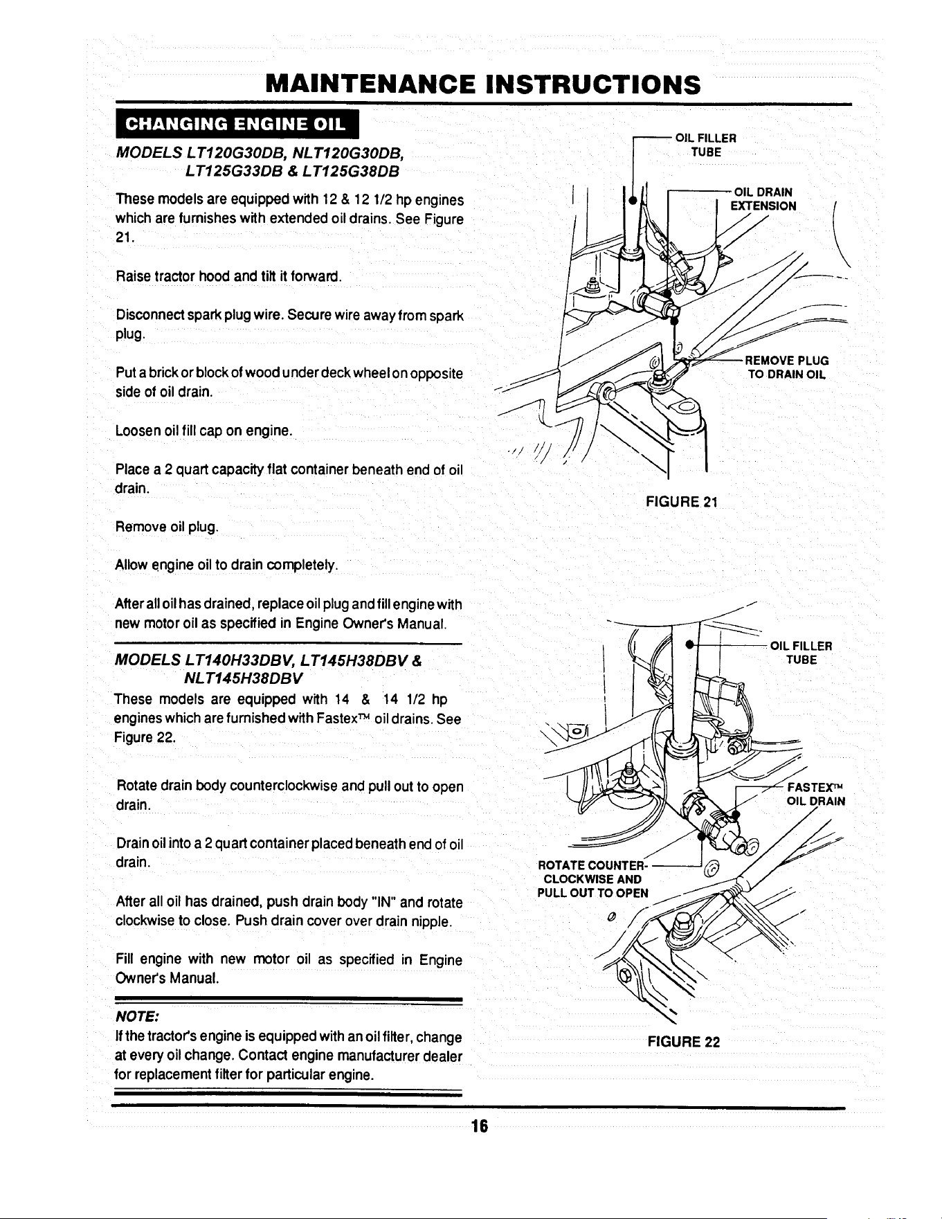
MAINTENANCE INSTRUCTIONS
MODELS L T120G30DB, NL T120G30DB,
LT125G33DB & LT125G38DB
These models are equipped with 12 & 12 1/2 hp engines
which are furnishes with extended oil drains. See Figure
21.
Raisetractorhood and tilt itforward.
Disconnectsparkplugwire. Securewire awayfrom soark
plug.
Put a brick or block of wood under deck wheel on opposite
side of oil drain.
Loosenoilfill cap on engine.
Placea 2 quart capacityflat containerbeneath end of oil
drain.
Removeoil plug.
Allowengineoilto drain completely.
After alloilhas drained, replace oilplugand fill enginewith
new motor oil as specifiedin Engine Owner's Manual.
MODELS LT140H33DBV, LT145H38DBV &
NL T145H38DB V
These models are equipped with 14 & 14 1/2 hp
engineswhichare furnished withFastexTM oildrains.See
Figure22.
Rotate drain body counterclockwise and pull out to open
drain.
Drainoil into a 2 quart container placed beneath end of oil
drain.
After all oil has drained, push drain body "IN" and rotate
clockwiseto close. Push drain cover over drain nipple.
Fill engine with new motor oil as specified in Engine
Owner's Manual.
NOTE:
Ifthetractor's engine is equipped withan oil filter, change
at everyoil change.Contactengine manufacturerdealer
for replacementfilter for particularengine.
ROTATE
CLOCKWISE AND
PULL OUT TO OPEN
16
FILLER
TUBE
OIL DRAIN
EXTENSION
\
FIGURE 21
FIGURE 22
PLUG
TO DRAIN OIL
L FILLER
TUBE
/
FASTEX'_
OIL DRAIN

MAINTENANCE INSTRUCTIONS
The followinglubricationpoints shouldbe servicedafter
each 25 operating hours to insure optimum performance
of the Series D Lawn Tractor.
FRONT WHEEL BEARINGS
Lubricateeach front wheel bearing through the grease
fitting on wheel hub. Using general purposegrease in a
greasegun, addgrease untilgreasepurgesfrom bearing.
See Figure 23.
AXLE SPINDLE
LUB RICATION
FITTING
AXLE SPINDLES
Lubricateeach axlespindlewith 1 shot ofgeneral purpose
grease. See Figure 23.
NOTE:
The R.H. spindle fitting faces forward and the L,H. spindle
fitting faces to the rear.
FRONT WHEEL BEARING
LUBRICATION FITTING
FIGURE 23
CLUTCH/BRAKE
PIVOT LUBRICATION
RTTING
CLUTCH//BRAKE PIVOT
The clutch/brake pivot is located on the L.H. underside of
the tractor and is lubricated with one shot of general
purpose grease. See Figure 24.
STEERING SECTOR GEAR
Lubricatewith a lightcoat of 30 wt. motoroil.See Figure
25.
STEERING SHAFT
Lubricatesteeringshaft wear pointswitha light coatof 30
wt. motoroil.
FIGURE 24
FUEL TANK
STEERING
SECTOR
SECTOR
GEAR
j"
17
FIGURE 25

MAINTENANCE INSTRUCTIONS
STEERING DRAG LINK
Lubricateboth ends of steering drag link with a small
amountof 30 wt. motoroilfrom anoilcan. See Figure26.
STEERING TIE ROD
Usingan oil can,filledwith30wt. motoroil, lubricateboth
endsof steeringtie rod. See Figure27.
BLADE ENGAGEMENT MECHANISM
Using30 wt. motor oil, lubricatethe blade engagement
mechanismpivot points,which are locatedon the R.H.
undersideof tractor.See Figure28.
PARK BRAKE LATCH
Using 30 wt. motor oil, lubricatethe park brake latch
mechanismpivot points, which are located on the L.H
undersideof tractor.See Figure29.
DECK LIFT MECHANISM
Lubricateallwear and pivotpoints ofthe deck liftmecha-
nismwith a thincoat of 30 wt. motor oil.
DRAG UNK
LUBRICATION
FIGURE 26
::::C'o:
FIGURE 27
LUBRICATE
COMPONENTS ON
UNDERSIDE
OF TRACTOR
".BLADE ENGAGEMENT
\
LEVER
FIGURE 28
PARK BRAKE
LATCH
LUBRICATE
COMPONENTS ON
UNDERSIDE
OF TRACTOR._
FIGURE 29
18

MAINTENANCE INSTRUCTIONS
The componentslistedshouldbe servicedon a regular
basisto insurethattheyare intopworkingcondition.Refer
to SERVICE SCHEDULE on Page 14 for recommended
serviceintervals.
AIR CLEANER
ENGINE AIR PRE-CLEANER
Theengineairpre-cleanershouldbe removedandcleaned
every25 operatinghours.See Figure30. Referto Engine
Owner'sManual for specificcleaninginstructions.
ENGINE AIR CLEANER
The engine air cleaner element shouldbe removedand
replacedevery 25 operatinghours.See Figure30. Con-
tactenginemanufacturer'sdealerfor correctreplacement
element.
ENGINE
AIR PRE.CLEANER
\
\
FIGURE 30
FUEL
TANK
SPARK PLUG
Removeand replaceenginesparkplugafter 100 operat-
ing hours. Refer to EngineOwner's Manual for correct
replacementplugand gap specifications.
FUEL FILTER
Theenginefuelfiltershouldbe replaced every100 oper-
atinghours.Remove the fuel filter as follows:
NOTE:
Itmay be necessary to drainthe fuel tank before removing
fuel filter to preventexcessivespillageof gasoline.
HOSE CLAMR
Raisetractorhood.
Removesparkplugwire(s)andsecureawayfrom plug(s).
Locate fuel filter. Remove hose clamps and fuel hoses
from bothsides of fuel filter. See Figure31.
NEW FUEL FII
PART No. 1-4359
FIGURE 31
Installnew fuel filtei"part number1°4359. See Figure32,
Fillfueltankwith freshgasoline.Refer to EngineOwner's
Manualforfuel specifications.
Reconnectsparkplugwire(s).
FIGURE 32
Lowertractor hood.
19

MAINTENANCE INSTRUCTIONS
ENGINE COOLING SYSTEM
The engine coolingsystemconsists of an engineshroud
and engine fins.These shouldbe kept clean and free of
debrisas needed or clean at least every 100 operating
houm.
The batteryshouldbe servicedevery25 hours of opera-
tion.
Raiseoperator'sseat.
Removethe two adjustingknobs.
Remove seat assemblyand moveforward.Use care not
to disconnectwiresfrom seat switch.See Figure33.
Removenegative(-) cable first.
Removepositive(+) cable.
REMOVE ADJUSTING
KNOBS AND MOVE _ / --
S ,TFO.WA.0, I / ,7
f
FIGURE 33
CHECKING BATTERY ELECTROLYTE
Carefully remove battery cell covers.
Visually check electrolyte level in each cell. Level shouldbe
1/8" to 3/8" above cell plates up to the fill rings.
ELECTROLYTE
3116" ABOVE
CELL PLATES
FIGURE 34
2O

MAINTENANCE INSTRUCTIONS
Usingdistilledwater, fill cells as needed to 1/8" to 3/8"
above cell plates.
Replace cell covers.
Charge battery if required.
Install positive(+) cable first.
Install negative(-) cable last.
Install seat assembly over battery and secure in position
with adjusting knobs. Leave knobs loose.
Lower operator's seat and adjust to desired position.
Raise seat and tighten adjusting knobs.
BATTERY CHARGING
The engine is equipped with a flywheel alternator to
charge the battery. If the tractor is not run regularly,
connect the battery to a charger monthlyto maintainthe
specific gravity at 1.250 or higher. If this reading falls
below 1.175, the batteryliquidmay freeze whentempera-
turesdropto around zero degrees F. To charge, connect
perinstructionsfumishedwithcharger,If time allows, slow
charge at 1 amp for ten hours, or as an alternate, fast
charge at 3 amps forfour hours. Observe all precautions
while charging.
.LEY
TRACTION DR! VE-BEL T
Check the tractiondrivebeltfordamage andwear after25
operatinghours. The traction drive belt is locatedon the
undersideofthe tractorandspansfromthe enginepulley's
top groove to the transmissionpulley. See Figure 35.
TRACTION --
DRIVE BELT
FIGURE 35
21

MAINTENANCE INSTRUCTIONS
Should the tractiondrive belt show signs of excessive
wear or damage, replace.
MOWER DECK REMOVAL
Placetractoron a firm,levelsurfacesuchasadrivewayor
garage floor and engage park brake.
Turnengine "OFF".
Raise hoodand removesparkplugwirefromsparkplug.
Securesparkplugwireawayfromsparkplug.See Figure
36.
\
UFT ROD
FRONT
UFT ARM
FIGURE 37
HAIR PIN
Lowerdeck to lowestsetting.
Disconnectdeck liftrodfromfrontliftarm. See Figure37
Removehair pinsfromfrontdeckhangerrod.See Figure
38.
RIGHT
SIDE
LO;T
Turnwheelsto the left, k'-,
Hold front of deck"UP"andslidefrontdeckhangerrodto ""'_%_- "'_
the right and out. FRONT DECK /"f_ _.._/_/_
HANOERROO/
Lowerfront of deck to ground. /
FRONT
Remove hair pin and flat washerfrom reardeck hanger LIFT HAIRPIN
bracket on bothsidesof tractor.See Figure39. ARM
FIGURE 38
SECURE WIRE
AWAYFROMPLUG ! t_
I
S
FIGURE 38
__.//_ SECTOR I
PIN AND WASHER_ _. ,
FROM BOTH _ /
../_.._.TO R PLATES "_' _.__L_
FIGURE 39
22

MAINTENANCE INSTRUCTIONS
Make note of hole used in sector plate.
Slide sectorplates off of rear deck hanger brackets.
Slide deck forward.
Remove deck drive beItfrom engine pulley bottom groove.
See Figure 40.
Slidedeck back and disconnect springfrom tension idler.
Pull deck from under tractor from R.H. side.
TRACTION DRIVE BELT REMOVAL
Remove two belt guide mounting bolts from each side of
tractor frame. See Figure 41.
Slide belt guide assembly to the rear and remove.
Disconnect traction belt idler pulley spring from tractor
frame. See Figure 42.
Loosen mounting nuts on traction drive belt tension and
stationary idlers just enough to allow belt to clear belt
guides. See Figure 43.
(30" & 33" BELT GUIDES SHOWN)
FIGURE 40
FIGURE 41
RIGHT REAR
TRACTOR FRAME
FIGURE 42
_I'ATIONARY------1 I-_1 _ LOO6EN
II I
IDLER
FIGURE 43
23

MAINTENANCE INSTRUCTIONS
Removetractiondrivebeltfromenginepulleytop groove.
See Figure44.
Removebelt from centerbeltguide.
Pullbelt untilitcan be removedfrom transmissionpulley.
TRACTION DRIVE BELT REPLACEMENT
Place new traction drive belt over transmission pulley and
span to engine pulley.
Place belt intotop grooveof enginepulley.
REMOVE
FROM PULLEY
Route belt through stationary and tension idlers. See
Figure45.
FIGURE 44
PULLEY
NOTE:
When installing new belt, make certain the stationary idler
is mounted in the hole closest to the L.H. side of the tractor.
See Figure 45. (See Page 29 for Belt Adjustment)
Make certainbelt is withinbeltguidesof idlers.
Attachtensionidlerspringtotractorframe. See Figure46,
Reinstall mower deck in reverse order of removal.
TENSION
IDLER
STATIONARY
IDLER
STATIONARY
IDLER
BRACKET
DE
I
RIGHT REAR
TRACTOR FRAME
STATIONARY
IDLER
FIGURE 45
\
\
!CTSPRING
TO FRAME
FIGURE 46
24

MAINTENANCE INSTRUCTIONS
30" & 33" DECK DRIVE BELT REMOVAL AND
REPLACEMENT
Inspect deck drive belt for excessive wear and damage
after every 25 operating hours. Replacement procedures
are as follows:
SPINDLE PULLEY
COVER
REMOVE
IDLER
Place tractoron a firm, level surface.
Turn engine "OFF".
Raise hood, remove spark plug wire from spark plug and
secure wire away from spark plug.
Remove mower deck.
Remove deck belt idler pulley. See Figure 47.
Remove spindle pulley cover. See Figure 47.
Remove old belt.
Replace with new belt, part number 2-2786 (30"), 2-6546
(33"), in reverse order.
/
/
FIGURE 47
SPINDLE----]
PULLEYFq L
IDLERPULLEY
FIGURE 48
Adjustidler pulley belt guide if necessary to obtain 1/16"
clearance between belt and belt guide. See Figure 48.
REMOVE IDLER ---_
38" DECK DRIVE BEL T REMOVAL/REPLACEMENT
Movetractorto a firm, levelsurface.
Turn engine "OFF".
Raise hood, remove spark plug wire from spark plug and
secure wnreaway from spark plug.
Remove deck from tractor.
Remove spindle belt guard. See Figure 49.
Remove tension idler. See Figure 49.
FIGURE 49
BELT GUARD
Remove old belt. _ ,__ . _ TENSION
p' 1,1,c,E, .cE\
Replace new belt, part number 3-5500, in reverse order. I.,_ (TYP'cAL) k_y(F_-'_o_
See Fngure 50 _pupl_ _ __._
FIGURE 50
25
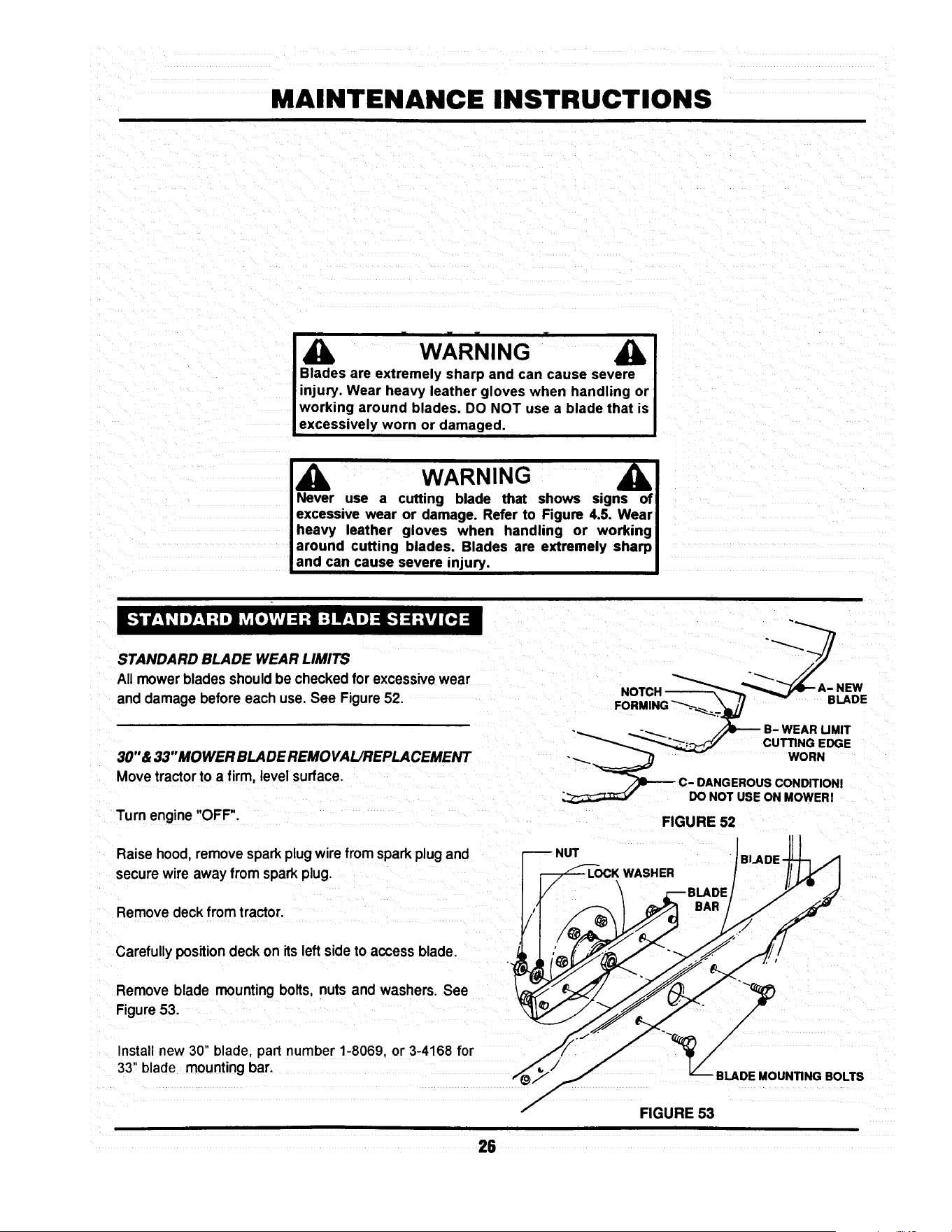
MAINTENANCE INSTRUCTIONS
" W.ARNING " A I
Blades are extremely sharp and can cause severe I
injury. Wear heavy leather gloves when handling or I
working around blades. DO NOT use a blade that is I
excessively worn or damaged. I
_Ib WARNING --_
I Never use a cutting blade that shows signs oq
excessive wear or damage. Refer to Figure 4.5. Wear I
heavy leather gloves when handling or working I
around cutting blades. Blades are extremely sharPl
and can cause severe injury. I
STANDARD BLADE WEAR LIMITS
All mowerblades shouldbe checked for excessivewear
anddamage before each use.See Figure52.
30" &33"MOWER BLADEREMOVAL/REPLACEMENT
Movetractorto a firm, levelsurface.
Turn engine "OFF".
-_ -_ _ B- WEARUMIT
__ CUTTINGEDGE
-_.._ WORN
_--- C- DANGEROUSCONDITIONI
DO NOT USEON MOWERI
FIGURE 52
I11
Raise hood, remove spark plug wire from spark plug and r-_ NUT BLADE-JJ-_ ./1
secure wire away from spark plug. 1 _-FF-'-LOCK WASHER I/I _ I
e ove eo ,ro traOor.
Install new 30" blade, pad number 1-8069, or 3-4168 for _J/ "_/
33" blade mounting bar. v__
BLADEMOUNTINGBOLTS
FIGURE 53
28

MAINTENANCE INSTRUCTIONS
Install blade mounting bolts, internal tooth lock washers
and nuts. See Figure 53
Torque blade to 30 to 40 Ft, Lbs.
38" STANDARD MOWER BLADE REMOVAL AND
REPLACEMENT
Move tractor to a firm, level surface.
Turn engine "OFF".
Raise hood, remove spark plug wire from spark plug and
secure wire away from plug.
Remove mowing deck from tractor.
Carefully position deck to access blades.
Remove blade mounting nut and cone washer from each
blade. See Figure 54.
Install new blades, part number 4-2998.
Secure blades with cone washers and mounting nuts. See
Figure 54.
Torque blade to 70 to 80 Ft Lbs.
(2- REQUIRED)
CONE
I WASHER
_ MOUNTING NUT
FIGURE 54
27

MAINTENANCE INSTRUCTIONS
SHARPENING STANDARD BLADE(S)
Blades should be kept sharp at all times. When the
blade(s) are dull, cut grass will be ragged and lawn will
usuallyturn brown.Sharpen standardbladesas follows:
Movetractorto a firm, levelsurface.
Tum engine "OFF'.
Raise hood,removesparkplugwirefromsparkplugand
securewire away from plug.
Remove mowing deck fromtractor.
Remove mower blade(s)
Inspectfor excessivewear or damage.
FIGURE 56
Never use a blade that shows signs of
exceaslve wear or damage. Refer to Figure
52 for standard blade wear limits.
Sharpenstandardmowerblade(s) at 25° angle+3°. See
Figure 56.
NINJATM BLADE WEAR LIMITS
The NinjaTM recyclingblade requiresmorefrequentser-
vice intervalsthan standardblades. Check the NinjaTM
recyclingblade for excessivewear or damageafterevery
use. See Figure 57.
NINJATM BLADE SHARPENING
The NinjaTM recycling blade requires more frequent
sharpening than standard blades due to its recycling
method.
Remove the NinjaTM blade by followingproceduresfor
standardblade removal.
Inspectthe NinjaTM bladefor excessivewear or damage.
See Figure57 for NinjaTM bladewear limits,
B- WEAR UMIT
(CRACKS OR NOTCHES
BEGIN TO APPEAR)
_ DANGEROUS CONDITIONI / _2._ ._,' 'It
DO NOT USE ON MOWERI "_ "_ _
FIGURE 57
28

MAINTENANCE INSTRUCTIONS
Never use a blade that shows signs of
excessive wear or damage. Refer to Figure
57 for NinJaTM blade wear limits.
Sharpen allcuttingedges ofthe NinjaTM recycling blade at
27° (+3°, -2 °) for optimum performance. See Figure 58.
Reinstall sharpened NinjaTM blade in reverse order of
removal.
Torque mounting bolts or nuts to proper standard blade
torque value for deck being serviced.
BLADE
FIGURE 58
Should a gradual loss of traction be noticed, it may be
necessary to adjust the traction drive belt tension. Adjust
as follows:
BELT
BRACKET
MORE
Movetractor to a firm, level surface.
Turn engine "OFF".
Raise hood remove spark plug wire from spark plug and
secure wire away from plug.
Remove mowing deck.
Remove the traction drive belt stationary idler mounting
bolt. See Figure 59.
Move the stationary idler one hole toward right side of
tractor for more tension.
NOTE:
Note the orientation of belt guide and make certain it
remainsin the same orientationafter moving idler.
NOTE:
Should less tension be required move stationaryidler
towardsright side of tractor. See Figure59.
|
IDLER
STATIONARY
MOUNTING BOLT
LESS
BELT GUIDE-
MAKE CERTAIN BELT
GUIDE ORIENTATION
IS MAINTAINED.
I
÷
STATIONARY
IDLER
MOUNTING BOLT
FIGURE 59
29

MAINTENANCE INSTRUCTIONS
Securestationaryidlerwith mountingbolt.
Place sparkplug wire onto spark plug.
Setpark brake.
Start Engine.
Visuallyinspecttractiondrive beltfor movement.
When properlyadjusted,the tractiondrivebelt shouldnot
have any movement or rotationwith the engine running
and park brake engaged.
Shouldmovement be present,readjusttractiondrive belt
to releasebeittension asdescribedinpreviousinstructions.
Movetractorto a firm, levelsurface. /
Turn engine"OFF'.
Raisehood,remove sparkplug wirefrom sparkplug and
securewire away fromplug.
Movebladeengagement leverdownto"OFF".See Figure ._._:
60. -::
E
ENGAGEMENT
TO "OFF"
Lower deckto lowest cutting position
Checkfrontto rear level.
If deck front to rear level is not correct,
thiscouldcause blade beltproblems.
30" & 33" DECKS
Measure length of blade cable extensionspring. See
Figure61.
Moveblade engagement lever to "ON".
Measure blade cable extension spring.Spring should
extend1"+_1/8"for properbelttension.See Figure61.
EXTENSION SPRING
FIGURE 60
FIGURE 61
3O

MAINTENANCE INSTRUCTIONS
To adjust tension, remove extension rod mountingbolt
and nut. See Figure62.
Move extension rodto next hole towards rear of deck and
securewith mountingbolt and nut. MOUNTING-
NUT & BOLT
Measure extension spring with blade engagement lever in
the "ON" and "OFF" positions. See Figure 61. Continue
adjustment until tension is correct.
I
-_LEAST TENSION/d
• _L / MOSTTENSlON
"-_ //
FIGURE 62
NOTE:
Before adjusting deck, bring tire pressureto properpsi.
Front12 psi, Rear 10 psi.
SIDE TO SIDE LEVEL
Movetractorto a firm, level surface.
Turn engine "OFF".
Raisehood, remove spark plugwire from spark plug and
securewire away from plug.
Move blade engagement lever to "OFF".
Place a piece of angle iron under center rear of deck.
SECTOR
PLATE
__ REMOV_ _
Remove hair pins and washers securing rear of deck to
sector plates. See Figure 65.
FIGURE 65
31

MAINTENANCE INSTRUCTIONS
Slidesectoroffof pinsandcarefullylowerdeckontoangle
iron.
33" DECK SHOWN
Rotate.blade(s) untilblade tipsare at each sideof deck.
•Measuredistancefrom blade tipto flooron each sideof LMEASUREFROM
deck. BLADE TIPS
TO FLOOR
Bladetips shouldbe within1/8"ofeach otherfor thedeck
to be consideredlevel. See Figure66.
If measurementdiffersmore than 1/8",adjustas follows:
Loosenfrontliftarm pivotboltonfrontof rightsiderail.See
Figure67.
NOTE:
The 38" deck does not incorporatea pivotbolt.
PIVOT BOLT
LOOSEN
SHOULDER BOLT
_-_ ANGLE IRON
FIGURE 66
f
Looseneccentricshoulderbolt. See Figure67.
Turneccentric"UP"or'DOWN" as requiredto leveldeck.
See Figure67.
Tighteneccentricshoulderbolt.
Tighten pivotbolt.
J
ECCENTRIC
AS REQUIRED
FIGURE 67
Place sector plates back onto rear lift arms and secure
withwashersand hairpins. SECTORPLATES
Make certainsector plates are mountedin the same _---_,,, ,,__ _;¢__ ________
holeson each side forproper frontto rearlevel.
FRONT TO REAR LEVEL-SECTOR PLATES --_-- "_-_
LOWEST OE
Removehairpinsand washerssecuringsectorplatesto
rearliftarms.See Figure 68. _ ~ _DECI(-S'_ING _ -------_-SETTING
Movesectorplate as requiredto raiseorlowerdeck. ___.-__ .)_1--'_ I_11_1_
DECK
REMOVE'
HAIR PIN & WASHER
FIGURE 68
32

MAINTENANCE INSTRUCTIONS
NOTE:
Thedeck shouldbe set sothat the rearofthe deck is 1/4"
lowerthan the front.See Figure69.
FRONT
X • 1/4"
33" DECK SHOWN
P'/////;! REAR
FRONT TO REAR LEVEL- FRONT LIFT ROD
If the sector plates are in their lowest setting and proper L__ MEASUREFROM
level cannot be obtained, adjust the front liftrod as follows: BLADETIPSTOFLOOR
x
f
FIGURE 69
Movedeck lift leverto #5 position.
30" & 33" DECK
Place a 2X4 woodenblockon edge underfrontcenter of
deck.
Place a 3X3 wooden blockunder rearcenter of deck.
NUT
/
/
Remove hair pins and washers securingsectorplates.
Lowerrear of deck onto3X3 block. See Figure68.
Removehairpinand washer securingfrontliftrodtofront
liftarm. See Figure 70.
Removefront lift rod andcarefullyrestfrontof deckonto
2X4 block.
Loosenjam nuton front liftrod.See Figure70.
•HAIR PIN
_ FRONT UFT ROD
FIGURE 70
Turnfrontliftrodhangerblockuntilitcan be reinstalledinto
frontlift arm withoutliftingdeck. See Figure70.
Secure lift rodto liftarm withwasher and hair pin.
Placesector platesonto rearhanger bracketsandsecure
withwashers and hair pins.
Raisedeck and remove wooden blocks.
Repeat steps for frontto rear level adjustment.Referto
FRONT TO REAR LEVEL- SECTOR PLATESo
Make certainsector plates are mountedin the same I
holes on each sidefor proper front to rear level. I
33

MAINTENANCE INSTRUCTIONS
NOTE:
Before adjusting deck, bring tire pressureto proper psi.
Front 12 psi, Rear 10 psi.
SIDE TO SIDE LEVEL
FRONT OF TRACTOR
BLOCK
Move tractor to a firm, level surface.
Turn engine "OFF".
Raise hood, remove spark plug wire from spark
plug and secure wire away from plug.
Move blade engagement lever to "OFF".
Place a 2-112" tall block under the front of the deck
centered between the front lift arms. See Fig 70a.
Place a 1-3/4" tall block under the rear of the
deck in the center. See Fig 70a.
Position the blades as shown in Fig 70a and lower
the deck onto the blocks.
1-3/4"TALLBLOCK_--_
FIGURE 70a
BLADESORIENTATEDFORSIDE-TO-SIDELEVELCHECK
38" DECK
Disconnect the front lift rod and the rear hanger
plates. See Fig 68 on page 32 and Fig 70b.
NUT
Put the lift lever in the 3rd position from low cut.
Measure the distance from each blade tip to the
floor. The measurements should be within 1/8"
of each other. (Factory setting)
If the difference is less than 1/8", go to next
section, Front-to-rear level.
If the difference is more than 1/8", adjust as
described in the following steps.
FRONT UFT
FIGURE 70b
Loosen the front adjuster nut until adjuster
moves freely. Then, tighten the nut until the
adjuster moves only when moderate force is
applied to one side of the deck. See Fig. 70c.
Adjust the side-to-side level of the blade tips by
moving one side of the deck up or down as
needed to obtain 118" or less side-to-side deck
level.
After leveling deck, re-tighten the adjuster nut
to from 30 to 40 ft-lbs.
FIGURE 70c
\
_ADJUSTER
NUT
33A

MAINTENANCE INSTRUCTIONS
Attach the rear hanger plates to the hole that
most closely aligns with the pin on the deck lift
bracket. Secure with washer and hair pin.
/h[ i !! !!ii! iiiii!i i ii! !i!!!i! !i Iiiiic i! !i ! Ni i ii!i Mii iii iii ii i i i i i i iiiiiiiiiiiiiii!j/hi
Make certain sectorplatesare mountedin the same I
holes on each side for proper frontto rear level J
FRONT OF TRACTOR
Adjust the swivel on the front lift rod until it
lines up with the hole in the front lift bracket.
(make sure the lift rod is at the top of the slot in
the deck bracket) Secure with hair pin.
FRONT TO REAR LEVEL
Position the blades as shown in Fig. 70d.
Measure the distance from the left front blade
tip to the ground and from the right rear blade
tip to the ground. The front left blade tip should
be between 1/8" and 3/8" higher than the right
rear (factory setting). If it is between 1/8" and
3/8" you are finished with adjustment.
If it is not within specifications, adjust by raising
or lowering the front of the deck using the
the swivel on the front lift rod. Turning the swivel
clockwise will raise the front of the deck. Turning
the swivel counter-clockwise will lower the front of
the deck.
BLADE TIP
\
\
RIGHT REAR BLADE TIP
FIGURE 70d
BLADESORIENTATEDFORFRONT-TO-REAR
LEVELCHECK
NOTE:
The deck should be set sothat the rear of the deck is 1/4"
lowerthan the front. See Fig. 70e.
33" DECK SHOWN
FRONT
JL MEASURE FROM
BLADE TIPS TO FLOOR
REAR
FIGURE 70e
X
f
33B

MAINTENANCE INSTRUCTIONS
STEERING SECTOR
Should excessive "PLAY" be present in the steering,
adjustas follows:
Tum Engine"OFF" and raise tractorhood.
Removespark plugwire from spark plug and securewire
away from plug.
From leftside of tractor,locatethe steeringsectorbelow
fuel tank. See Figure 71.
Looseneccentricmounting nut.
Rotate eccentric clockwise until steering "PLAY" is re-
duced.See Figure 71.
Tighteneccentricmounting nut.
Replacespark plugwire onto sparkplugand lowerhood.
FIGURE 71
If movement of tractor does not correspond with the
selectedspeedonshiftquadrant,adjustthe speedcontrol
lever as follows:
Withengine running,drivetractor and move shiftleverto
locateneutral.
Turn engine "OFF".
Raise hood,remove sparkplugwire fromsparkplugand
securewire away from plug.
Locate speed control lever mount behind right rear tire.
See Figure72.
Loosenmountingnuts.
Movethe speed controlleveruntilit is indirectrelationto
the neutral"N"position on quadrant. See Figure 73.
Tighten mounting nuts.
SPEED CONTROL
LEVER MOUNT
ED
CONTROL
LEVER
®
MOUNTING (_
NUTS
FIGURE 72
SPEED CONTROL LEVER
MOVE TO NEUTRAL
(N) POSITION
FIGURE 73
34

MAINTENANCE INSTRUCTIONS
HYDRO DRIVE MODELS
To be properlyadjusted,the brake shouldstopthe tractor
inapproximately6 feet from top speed when the clutch/
brake pedal is fully depressed.
Adjustbrake when necessary as follows:
Turnengine "OFF'.
Raise hood, remove spark plugwire fromsparkplugand
securewire away from plug.
Locatebrake adjustmenton rightsideoftractor infrontof
andbehind rightrear wheel. See Figure74.
Turn nut clockwise to increase braking action or, coun-
terclockwiseto decrease brakingaction.See Figure 74.
Replace spark plugwire, startengine andtest brake.
Continue adjustment as described above until proper
adjustmentis achieved.
GEAR DRIVE MODELS
Tobe properlyadjusted,the brakeshouldstopthe tractor
inapproximately6 feet fromtop speed when the clutch/
brakepedal is fully depressed.
Adjustbrake when necessaryas follows:
Turn engine "OFF".
Raisehood, remove sparkplugwire from spark plug and
securewire away from plug.
Locatebrake adjustmenton rightsideof tractorin backof
and behind rightrear wheel. See Figure 75.
Turn nut clockwise to increase braking action or, coun-
terclockwiseto decrease brakingaction.See Figure75.
Replace spark plugwire, startengine and test brake.
Continue adjustment as described above until proper
adjustmentis achieved.
\
FIGURE 74
ADJUSTMENT
FIGURE 75
BRAKE
35

ELECTRICAL
Figure 76 illustratestypical hamess mutingon all the
Series D Lawn Tractors. Use this when locatingvarious
electricalcomponents.
_---- O BATI1ERY
NEGATIVE (-)
-TO BATTERY
PosmvF.(+)
TERMINAL
D
(UNDER SEAT)
R,H°
HEADLIGHT
SWITCH
BLADE ENGAGEMENT
LEVER SWITCH
SWITCH
20 AMP-
FUSE
BRAKE
SWITCH
HEADUGHT
HEAD
HARNESS
HARNESS
GROUND
TO ENGINE
FIGURE 76
36
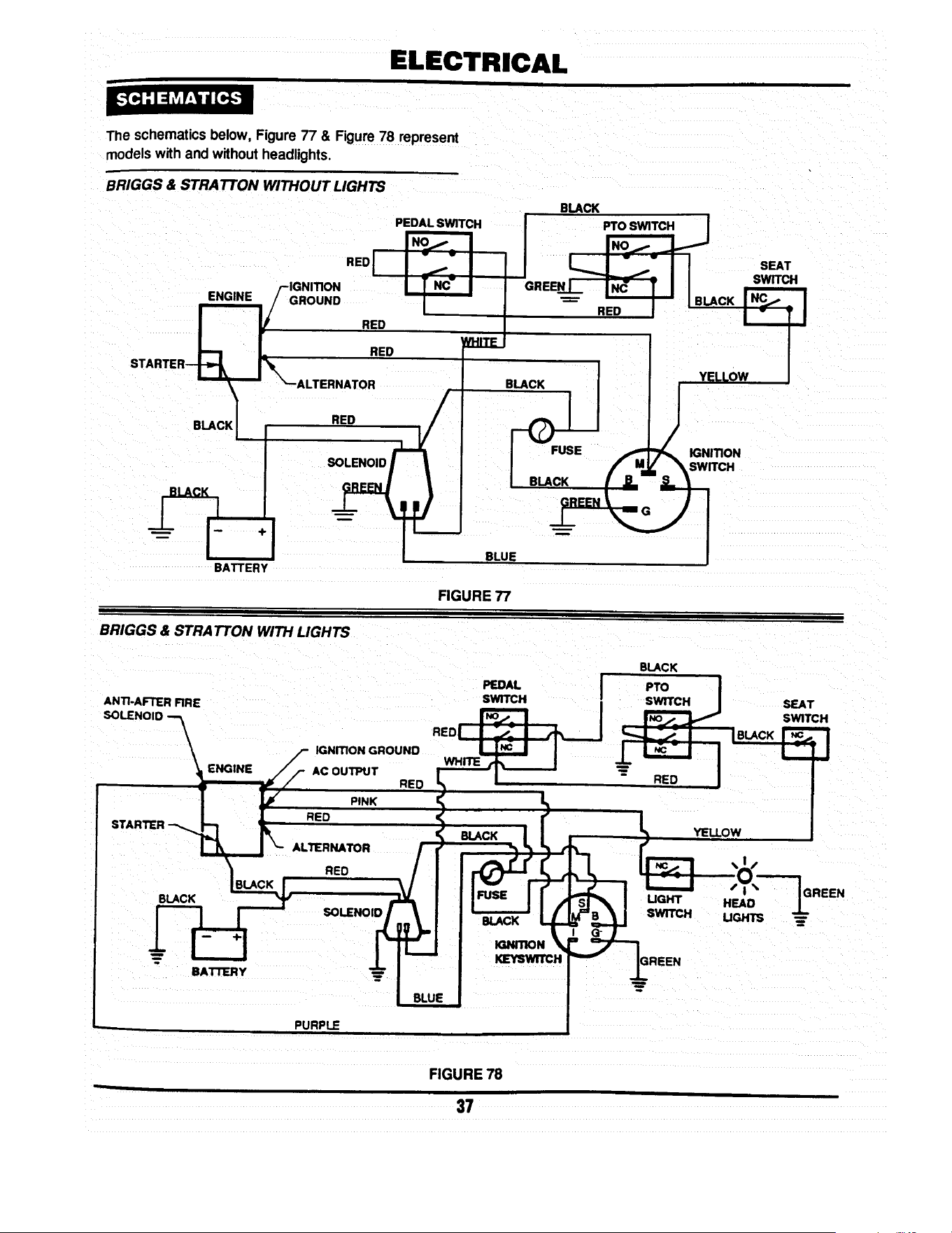
ELECTRICAL
The schematics below, Figure 77 & Figure 78 represent
models with and without headlights.
BRIGGS & STRA TTON WITHOUT LIGHTS
STARTER k
"EDI
/-IGNITION
ENGINE /GROUND
RED
RED
'_--ALTERNATOR
BLACK RED
BATTERY
PEDAL SWITCH
INoj. I
I
I
BLACK
GREENI I N_ I II
I I BLACK
RED
I
B_ YELLOW
BLUE
FIGURE 77
BRIGGS & STRA TTON WITH LIGHTS
ANTI-AFTER FIRE
SOLENOID --_
\
\
ENGINE
STARTER
BLACK
BAI"rlERY
IGNmON GROUND
AC OUTPUT
RED
PINK
RED
ALTERNATOR
RED
SOLENOID
RED
PEDAL
SWITCH
BLACK
PTO
SWITCH
RED
BLACK
BLACK
UGHT
SWITCH
_mTION
KEYswrrc_
YEllOW
SEAT
SWITCH
IN_ I
I" Tl
r
HEAD
UGHTS
SEAT
SWITCH
GREEN
PURPLE
FIGURE 78
37

!
3 YEAR LIMITED WARRANTY
For three (3) years from purchase date for the original purchaser's residential, non-commercial use, SNAPPER, through
any SNAPPER dealer will replace, free of charge (except for taxes where applicable), any part.or parts found upon
examination by the factory at McDonough, Georgia, to be defective in material or workmanship or both.
For ninety (90) days from purchase date for the odginal purchaser's commercial, rental, or other non-residential use
SNAPPER, through any SNAPPER dealer will replace, free of charge, any part or parts found upon examination by th=
factory at McDonough, Georgia, to be defective in material or workmanship or both.
All transportation costs incurred by the purchaser in submitting material to a SNAPPER dealer for replacement under
this warranty must be paid by the purchaser.
This warranty does not apply to engines and their components, hydro transmissions, gear drive transmissions and
batteries, as these items are warranted separately. This warranty does not apply to parts that have been damaged by
accident, alteration, abuse, improper lubrication, normal wear, or other cause beyond the control of SNAPPER. This
warranty does not cover any machine or component part that has been altered or modified changing safety,
performance, or durability.
There is no other express warranty.
DISCLAIMER OF WARRANTY
Implied warranties, including those of merchantability and fitness for a particular purpose, are limited to three
(3) years from purchase date for the original purchaser's residential or other non-commercial use, and ninety
(90) days from purchase for the original purchaser's commercial, rental or other non-residential use, and to the
extent permitted by law, any and all implied warranties are excluded. This is the exclusive remedy. Liabilities
for consequential damages, under any and all warranties are excluded.
Some states do not allow limitations on how long an implied warranty lasts, or do not allow the exclusion or
limitation of incidental or consequential damages, so the above limitation or exclusion may not apply to you.
This warranty gives you specific legal rights, and you may also have other rights which vary from state to state.
WARNING: THE USE OF REPLACEMENT PARTS OTHER THAN GENUINE SNAPPER PARTS MAY IMPAIR THE
SAFETY OF SNAPPER PRODUCTS AND WILL VOID ANY LIABILITY AND WARRANTY BY SNAPPER
ASSOCIATED WITH THE USE OF SUCH PARTS.
IMPORTANT: Please fill outthe attachedSNAPPER Product RegistrationCard immediatelyand mail to:
Snapper's Product Registration Center, P.O. Box 777, McDonough, Georgia 30253

SERVICE NOTES

SERVICE NOTES

Safety Instructions & Operator's Manual for
8NAPPER
LAWN TRA C TOR
HYDROSTA TIC &
GEAR DRIVE
SERIES D
IA WARNING: The engine exhaust from this product contains chemicals known to the State I
of Califomia to cause cancer, birth defects or other reproductive harm.
I
COPYRIGHT © 1998
SNAPPER INC
ALL RIGHTS RESERVED
MANUAL No. 3-5576 (REV. 2, 6/98)
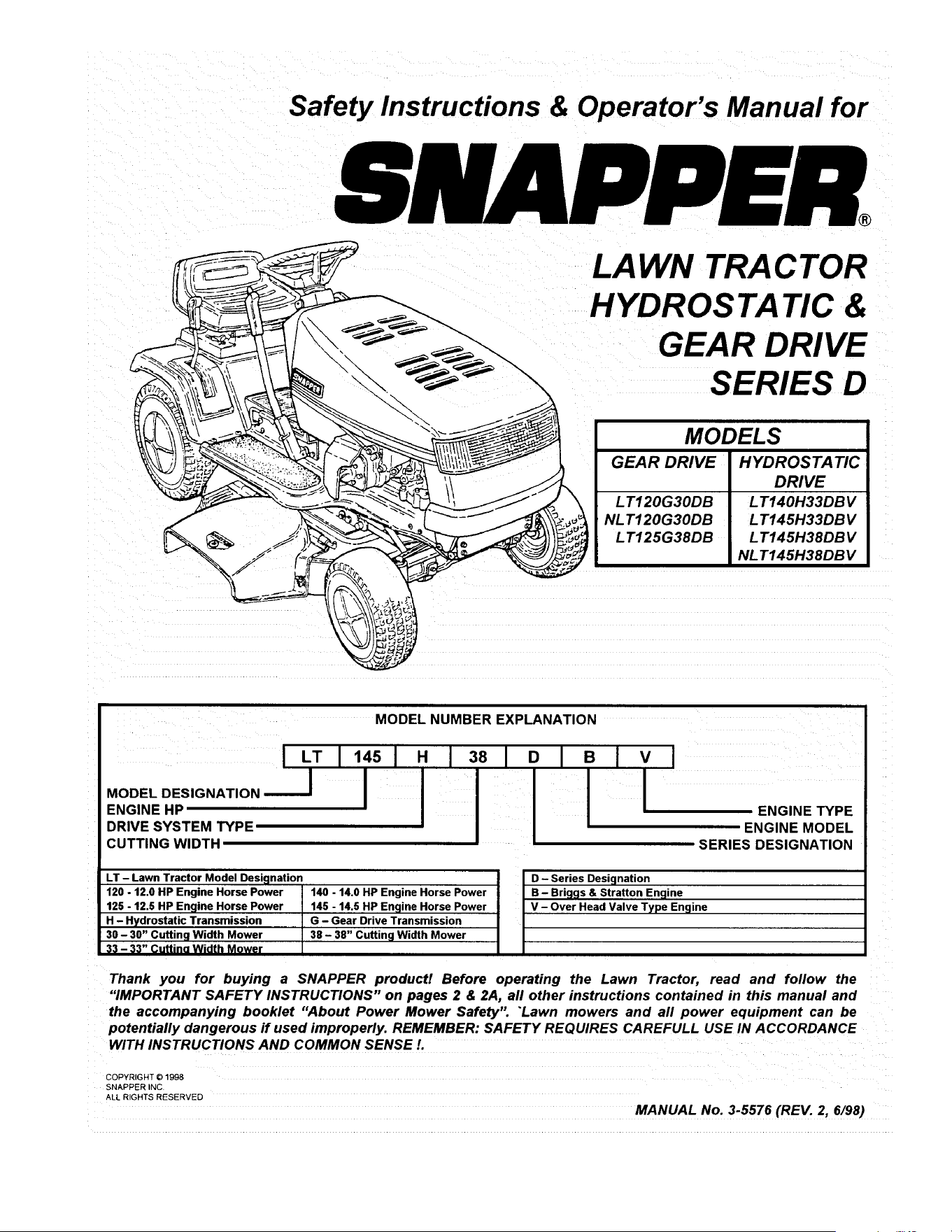
Safety Instructions & Operator's Manual for
,SNAPPER,
LAWN TRA CTOR
HYDROSTATIC &
GEAR DRIVE
SERIES D
MODELS
GEAR DRIVE HYDROSTATIC
DRIVE
LT120G30DB LT140H33DBV
NLT120G30DB LT145H33DBV
LT125G38DB LT145H38DBV
NLT145H38DBV
I
MODEL DESIGNATION
ENGINE HP
DRIVE SYSTEM TYPE
CUTTING WIDTH
MODEL NUMBER EXPLANATION
LT I 145I H 1381 O I B I V I
i ENGINE TYPE
; ENGINE MODEL
SERIES DESIGNATION
LT - Lawn Tractor Model Designation
120 - 12.0 HP Engine Horse Power
125 - 12,5 HP Engine Horse Power
H - Hydrostatic Transmission
30 - 30" Cutting Width Mower
33 - 33" Cuttino Width Mower
140 - 14.0 HP Engine Horse Power
145 - 14.5 HP Engine Horse Power
G - Gear Drive Transmission
38 - 38" Cutting Width Mower
D - Series Designation
B - Briggs & Stratton Engine
V - Over Head Valve Type Engine
Thank you for buying a SNAPPER product! Before operating the Lawn Tractor, read and follow the
"IMPORTANT SAFETY INSTRUCTIONS" on pages 2 & 2A, all other instructions contained in this manual and
the accompanying booklet "About Power Mower Safety". "Lawn mowers and all power equipment can be
potentially dangerous ff used improperly. REMEMBER: SAFETY REQUIRES CAREFULL USE IN ACCORDANCE
WITH INSTRUCTIONS AND COMMON SENSE/.
COPYRIGHT © 1998
SNAPPER NC
ALL RIGHTS RESERVED
MANUAL No. 3-5576 (REV. 2, 6/98)

IMPORTANT SAFETY INSTRUCTIONS
WARNING: This powerful cutting machine is capable of amputating hands and feet and can throw objects that
can cause injury and damage! Failure to comply with the following SAFETY instructions could result in
serious injury or death to the operator or other persons. The owner of the machine must understand these
instructions and must allow only persons who understand these instructions to operate machine. Each
person operating the machine must be of sound mind and body and must not be under the influence of any
substance which might impair vision, dexterity or judgment. If you have any questions pertaining to your
machine which your dealer cannot answer to your satisfaction, call or write the Customer Service Department
at SNAPPER, McDonough, Georgia 30253. Phone: (1-800-935-2967).
PROTECTION FOR CHILDREN
Tragic accidents can occur if the operator is not alert
to the presence of children. Children are often
attracted to the machine and the mowing activity.
Never assume that children will remain where you
last saw them.
1. KEEP children out of the mowing area and under
the watchful care of a responsible adult.
2. DO NOT allow children in yard when machine is
operated (even with the blade OFF).
3. DO NOT allow children or other passengers to
ride on machine or on attachments (even with the
blade OFF). They may fall and be seriously
injured.
4. DO NOT allow pre-teenage children to operate
machine.
5. ALLOW only responsible adults & teenagers with
mature judgment under close adult supervision to
operate machine.
6. BE SURE the area is clear of others before
mowing and turn machine OFF if anyone enters
the area.
7. DO NOT mow in reverse unless absolutely
necessary. LOOK BEHIND and down for small
children before and when backing.
8. USE EXTRA CARE when approaching blind
corners, shrubs, trees, or other objects that may
obscure vision.
PROTECTION AGAINST TIPOVERS
Slopes are a major factor related to loss-of-control
and tip-over accidents, which can result in severe
injury or death. All slopes require extra CAUTION. If
you cannot back up the slope or if you feel uneasy on
it, DO NOT mow it. Use extra care with grass catchers
or other attachments; these can change the stability
of the machine.
1. DO NOT operate machine on slopes exceeding 15
degrees (27% grade).
2. Exercise EXTREME CAUTION on slopes above 10
degrees (18% grade). Turn blade OFF when
traveling uphill. Use first speed and avoid sudden
or sharp turns.
3. DO NOT mow back and forth across face of
slopes. Mow up and down.
PROTECTION AGAINST TIPOVERS
(Continued From Previous Column)
4. AVOID uphill starts. If machine stops going uphill
or tires lose traction, turn blade OFF and back
slowly down the slope.
5. STAY ALERT for holes and other hidden hazards.
Tall grass can hide obstacles. Keep away from
ditches, washouts, culverts, fences and
protruding objects.
6. KEEP A SAFE DISTANCE (at least 3 feet) away
from edge of ditches and other drop offs. The
mower could turn over if an edge caves in.
7. Always begin forward motion in the #1 speed
position.
8. Use weights or a weighted load carrier in
accordance with instructions with a grass catcher
on slopes above 10 degrees (18% grade).
9. DO NOT put your foot on the ground to try to
stabilize the machine.
10. DO NOT mow on wet grass. Reduced traction
could cause sliding.
11. DO NOT mow under any condition where traction,
steering or stability is doubtful without first test
driving over the terrain with blade OFF.
PREPARATION
1. Read this manual, get to know where all controls
are located and practice how to use them before
starting for the first time, and at the beginning of
each season. Read and follow Warnings and
Instructions on engine and machine. Read and
follow operator's manual and instructions
furnished with attachments.
2. Only mature, responsible persons shall operate
the machine and only after proper instruction.
3. Handle fuel with extra care. Fuels are flammable
and vapors are explosive. Use only an approved
fuel container. Never remove fuel cap or add fuel
with engine running. Add fuel outdoors only with
engine stopped and cool. Clean spilled fuel from
machine. DO NOT smoke.
4. Practice operation of machine with BLADE OFF to
learn controls and develop skills.
(Continued on Next Page}
IMPORTANT SAFETY INSTRUCTIONS
PREPARATION
(Continued From Previous Page)
5. Check the area to be mowed and remove all
objects such as toys, wire, rocks, limbs and other
objects that could cause injury if thrown by blade
or interfere with mowing.
6. Keep people and pets a safe distance from
machine.
7. Check shields, deflectors, switches, blade
controls and other safety devices frequently for
proper operation and location.
8. Make sure all safety decals are clearly legible.
Replace if damaged.
9. Protect yourself when mowing and wear safety
glasses, long pants and substantial footwear.
10. Know how to STOP blade and engine quickly in
preparation for emergencies.
11. Use extra care when loading or unloading the
machine into a trailer or truck.
12. Check grass catcher components frequently for
signs of wear or deterioration and replace as
needed to prevent injury from thrown objects
going through weak or worn spots.
OPERATION
1. Mount and dismount machine from left side.
2. Start engine from operator's seat, if possible.
Make sure blade is OFF and parking brake is set.
3. STOP blade, STOP engine, set parking brake and
remove key when leaving machine.
4. DO NOT operate machine unless properly seated
with feet on feet rests or pedal(s).
5. STOP BLADE and ENGINE and make sure blade
has stopped before removing grass catcher or
unclogging mower to prevent loss of fingers or
hand.
6. Blade must be OFF except when cutting grass.
Set blade in highest position when mowing over
rough ground.
7. Keep hands and feet away from rotating blade
underneath deck. NEVER place foot on ground
while BLADE is ON or machine is in motion.
8. Deflector or entire grass catcher must be in place.
NEVER point discharge at people, passing cars,
windows or doors.
9, Slow down before turning.
MAINTENANCE
1. Never store machine or fuel container inside
where fumes may reach an open flame, spark or
pilot light such as in a water heater, furnace,
clothes dryer or other gas appliance. Allow
engine to cool before storing machine in an
enclosure. Store fuel container out of the reach of
children in a well ventilated, unoccupied building.
2. Keep engine free of grass, leaves or excess
grease to reduce fire hazard and engine
overheating.
3. When draining fuel tank, drain fuel into an
approved container outdoors and away from open
flame.
4. Check brakes frequently; adjust, repair or replace
as needed.
5. Keep all bolts, nuts and screws properly tight.
Check that all cotter pins are in proper position.
6. Always provide adequate ventilation when
running engine indoors. Exhaust gases contain
carbon monoxide, an odorless and deadly
poison.
7. Disconnect negative (black) cable from battery
before performing maintenance or service.
Cranking engine could cause injury.
8. Never work under machine without safety blocks.
9. Service engine and make adjustments only when
engine is stopped. Remove spark plug wire(s)
from spark plug(s) and secure wire(s) away from
spark plug(s).
10. DO NOT change engine governor speed settings
or overspeed engine.
11. Lubricate machine at intervals specified in
manual to prevent controls from binding.
12. Mower blades are sharp and can cut. Wrap the
blades or wear heavy leather gloves and use
CAUTION when handling them.
13. NEVER test for spark by grounding spark plug
next to spark plug hole; spark plug could ignite
gas exiting engine.
14. Have machine serviced by an authorized
SNAPPER dealer at least once a year and have the
dealer install any new safety devices.
15. Use only genuine SNAPPER replacement parts to
assure that original standards are maintained.
10. Watch out for traffic when near or crossing
roadways.
11. STOP engine immediately after striking an
obstruction. Inspect machine and repair damage
before resuming operation.
12. Mow only in daylight or with good artificial light.
13. Move joystick (if equipped) SLOWLY to maintain
control during speed and directional changes.
14. Exercise CAUTION when pulling loads. Limit
loads to those you can safely control and attach
loads to hitch plate as specified with SNAPPER
attachment instructions.
2A

TABLE OF CONTENTS
IMPORTANT SAFETY INSTRUCTIONS ...... 2 & 2A
TABLE OF CONTENTS ........................................ 3
FAMILIARIZATION ............................................. 4-5
Serial & Model Number Location ........................... 4
Controls .................................................................... 5
Components ........................................................... 5
OPERATING INSTRUCTIONS ........................ 6-11
Pre-start Checklist ................................................... 6
Adjusting Operator's Seat ....................................... 6
Starting & Stopping Engine ....................................... 7
Starting & Stopping Wheel Drive ............................... 8
Setting & Releasing Parking Brake ..........................
Starting & Stopping Mower Blades .......................... 9
Adjusting Cutting Height ......................................... 10
Raising Chute Deflector ......................................... 10
Rolling Tractor W_h Engine Off ......................... 9-10
Tips on Mowing ....................................................... 11
ACCESSORIES .................................................. 11
TROUBLESHOOTING GUIDE ....................... 12-13
MAINTENANCE INSTRUCTIONS ................. 14-35
Service Schedule ......................................... 14
Maintenance Parts ....................................... 14
Hydrostatic Transmission Oil .................... 15
To CheckOilLevel...............................................
Changing Engine Oil ................................... 16
Lubrication (Tractor] .............................. 17-18
Front Wheel Bearings ......................................... 17
Axle Spindles ....................................................... 17
Steering Shaft ...................................................... 17
Clutch/Brake Pivot............................................... 17
Steering Sector Gear .......................................... 17
Steering Drag Link .............................................. 18
Steering Tie Rod ................................................. 18
Park Brake Latch ................................................ 18
Deck Lift Mechanism .......................................... 18
Blade Engagement Mechanism ......................... 18
Engine Service ............................................. 19
Engine Air Pre-Cleaner ....................................... 19
Engine Air Cleaner .............................................. 19
Spark Plug ........................................................... 19
Fuel Filter ........................................................... 19
Engine Cooling System ...................................... 20
MAINTENANCE INSTRUCTIONS (Continued)
Battery Service ............................................. 20-21
Battery Electrolyte Check ............................ 20
Battery Charging ................................................ 21
Mower Deck Removal/Reinstallation .......... 22-23
Standard Mower Blade Service ................... 26-28
Standard Blade Wear Limits ....................... 26
Blade Removal/Replacement ...................... 26-27
33" Mower Blade ............................................ 26
38" Mower Blade ............................................ 27
Sharpening Standard Blade(s) ................ 28
Ninja Mower Blade Service .................................. 28
Ninja Blade Wear Limits................................28
Ninja Blade Sharpening .................................29
Belt Service .................................................. 21-25
Mower Drive Belt Removal/Replacement 25
33" & 38" Deck Drive Belt.............................25
Traction Drive Belt Service .................... 21-24
Traction Drive Belt Removal ......................... 23
Traction Drive Belt Replacement .................. 24
Traction Drive Belt Adjustment ................ 29-30
Deck Level Adjustment .............................. 31-33B
Side to Side Level ............ 31-32 & 33A-33B
Front to Rear Level ........................32-33 & 33B
Sector Plates..................................................32
FrontLiftRod ......................................33 & 33A
Shifter Adj ustment ............................................ 34
Steering Adjustment ......................................... 34
Wheel Brake Adjustment .................................. 35
ELECTRICAL SYSTEM ................................. 36-37
Wiring Harness Routing ...................................... 36
DIAGRAMS, Briggs Engine w/o lights................ 37
DIAGRAMS, Briggs Engine w/lights ................... 37
WARRANTY ....................................................... 38
PRIMARY MAINTENANCE ............................ 39-42

FAMILIARIZATION
H_.'t::1:! P"_IHE:I _v,(o] _] ::!mid_Ill Lv,I :1:1:1 Ko]).]P',_In/ (o]; •
The serial and model number of the SNAPPER Series D
Lawn Tractor are located on the rear face of the tractor
frame as shown in Figure 1. Record these numbers inthe
space provided. They will be useful in ordering parts or
accessories for the tractor.
!
MODEL NUMBER
SERIAL NUMBER
I
REAR VIEW
_/. !_OF _ACTOR
/ \
/
SNAPPER. McOn.p. = 3o2ss
SER XXXXXXXX MOD XXXXXXXXXXX
KW X.XX KG XXX
HP X.X LBS XXX
RPM XXXX
_iiiii_ii_ii_iiiiiii_}iiii_ii!i!_!iii_i_!__e_n_iii!i!i!i_iii!_!i!iiii_!_i_ii_i!_i_i_!
FIGURE 1
m[o{o]: ind:To] _!
NOTE: STEERING WH EEL & OPERATOR'S SEAT NOT SHOWN IN THIS VIEW.
All operator'sshould be acquaintedwith the operator's
controlsbefore attemptingstart-up or operationof the
SeriesD LawnTractor.See Figure2.
PEDAL
ENGINE SP
CONTROL
PARK BRAKE
LATCH
(HYDRO ONLY)
__W HEADLIGHT
ITCH
DECK
UFT
.°v°.
IGNITION
I_J/ SWITCH
-_ BLADE
! E_G_RGEMENT
SPEED
CONTROL
LEVER
FIGURE 2
4
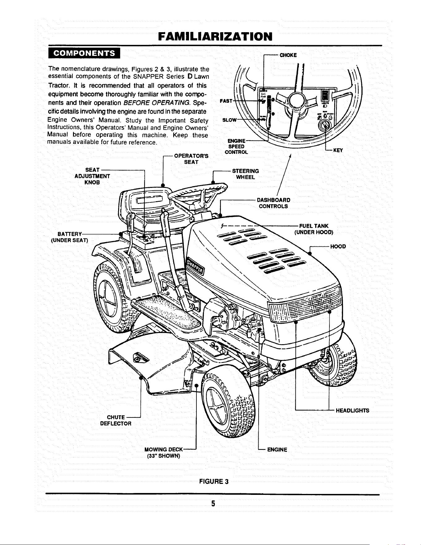
FAMILIARIZATION
[_o] Lv,I ".,To]_,1:1_,b u_
The nomenclature drawings, Figures 2 & 3, illustrate the
essential components of the SNAPPER Series D Lawn
Tractor. It is recommended that all operators of this
equipment become thoroughly familiar with the compo-
nents and their operation BEFORE OPERATING. Spe-
cific details involving the engine are found in the separate
Engine Owners' Manual. Study the Important Safety
Instructions, this Operators' Manual and Engine Owners'
Manual before operating this machine. Keep these
manuals avail able for future reference.
SEAT
ADJUSTMENT
KNOB
BATTERY
(UNOER SEAR
---OPERATOR'S
SEAT
FAST_i
SLOW-_
ENGINE-_-_
SPEED
CONTROL
_ CHOKE
!
/
WHEEL /
/
.DASHBOARD
CONTROLS
FUEL TANK
(UNDER HOOD)
CHUTE
DEFLECTOR
HEADUGHTS
MOWING DECK
(33" SHOWN)
ENGINE
FIGURE 3

OPERATING INSTRUCTIONS
I d :! =5.'t if:! :_iI It.,].-I :(H ;I ii [..1,i
Make the followingchecks and perform serviceas re-
quiredbeforeeach start-up.
Checktires and add air as needed to bringpressure to
12psi in fronttires and 10 psi in reartires. If guardsare
missingor damaged, Replace BEFORE usingmower.
Checkguards,deflectorsand coversto makesure all are
inplaceand securelytightened.
Checkengineoil.Addoil as neededtobringup to, but not
over,thefullmark.Refertothe engineowner'smanualfor
oil specifications.
Checkoperator'sseat adjustment.Adjustas necessary.
Check blade engagement lever to insure it operates
properly.The blade engagement lever must be moved
manuallyfrom "ON" to "OFF"to stop blade.
TANK
/
CAP
_.AFTER FILLING
TANK
Clean exteriorsurfacesof cuttingdeck,engineandtractor
from any accumulation of grass clippingsand debris.
Keepengineair intake screensandcoolingfinscleanatall
times.
Withengine "OFF"move the tractoroutsideand addfuel
to the fuel tank. Securely tightenfuel cap after refueling.
See Figure 4. Refer to engine owner's manual for fuel
specifications.
FIGURE 4
FRONT TO REAR ADJUSTMENT
With engine"OFF", raise operator'sseat and loosenthe
two adjustingknobs onthe seat support.See Figure5.
Lowerthe seat.
LOOSEN ADJUSTING
KNOBS TO ADJUST SEAT
Sit in the operator's seat and slide the seat forward or
backward until the clutch/brakepedal can be fully de-
pressedcomfortably.
Raiseseatandtightenthe adjustingknobstosecureseat
inposition.
6
FIGURE 5

OPERATING INSTRUCTIONS
:,In#,I :_idI: [rl:_..'t liD] "J"JI: [tl =1_[r] I: I =i
I _
STARTING ENGINE
Take a comfortablepositionin seat of ridingmower,look
aroundto make surethat the area you are goingto mow
is clear of people, children and pets. Take note of any
stationaryobstacles!
NOTE:
The interlocksystemwillpreventthe engine from starting
ifthe blade engagementleveris in the "ON" (up)position.
If the interlocksystemeverfails to work, DO NOT OPER-
ATE the tractoruntilthe interlockhas been repaired.
Pushblade engagement leverdowntothe "OFF"position.
See Figure6.
ENGAGEMENT
LEVER
PUSH BLADE ENGAGEMENT
TO START ENGINE
\
\
FIGURE 6
Depress the clutch/brakepedal fully. See Figure7.
NOTE:
The seat interlockwill shut off the engine ifthe operator
gets offthe seat withoutsetting the parkingbrakeleveror
ifthe bladeis running.If the interlockeverfailstowork,DO
NOT OPERATE the tractoruntil the interlockhas been
repaired.
Choke enginefor cold startingby moving engine speed DOWN
controlto "CHOKE" position. Littleor no chokingwill be '_',X _
needed when restarting a warm engine. See Figure 8.
\
Insert key inswitch.
L
Turn key to "START" position to crank engine and hold
until engine starts, then release key.
NOTE:
DO NOT crank engine for more than five secondsat a
time. This will help prevent the starterfrom overheating
an_or runningdownthe battery. Ifcrankingtime is more
than five seconds, locate and correct cause of starting
problem.
After engine starts,release key, move the engine speed
controlto the "FAST" positionandallow enginetowarmup
before proceeding.See Figure8.
STOPPING ENGINE
Turn key to "STOP". See Figure8.
FIGURE 7
CHOKE
ENGINE -_-_-._ _. _--- _--_,,_
LKEy
FIGURE 8

OPERATING INSTRUCTIONS
_._ net :_unlI: [_lr:l-_ n[o]"J"JI _[riYl: 1:1=1nl ,] ;1Lvi=
STARTING WHEEL DRIVE OF HYDRO MODELS
Shift speed controllever to neutral.
Start engine.
Release brake pedal.
Slowlyshiftspeed controlleverforwardfor forwardmotion
or to the rear for reverse motion.See Figure9.
STOPPING WHEEL DRIVE
Fully depress clutch/brake pedal to stop wheel drive.
Shift speed control lever to neutral. See Figure 10.
NOTE: (HYDRO DRIVE MODELS ONLY)
When the tractor is moving forward and the clutch/brake
pedal is pushed all the way down, the speed control
handlewillautomaticallyreturnto approximately1/3offull
forward speed. Move handle to desired positionafter
releasing brake pedal.
STARTING WHEEL DRIVE OF GEAR MODELS
Shiftspeed controlleverto neutral.
Start engine.
Fullydepressclutch/brakepedal.
Move speed controlhandle forward to Firstspeed.
See Figure 11.
Slowly release clutch/brakepedal to begin motion.
FORWARD
SPEEDS
CLUTCH/BRAKE
PEDAL
SPEED CONTROL
HANDLE
HANDLE
REVERSE
I
FIGURE 9
CLUTCH/BRAKE
PEDAL TO STOP
WHEEL MOTION
FIGURE 10
NOTE: (GEAR DRIVE MODELS ONLY)
The clutch/brake pedal must be fully depressed when
changingspeed.
FORWARD
SPEEDS
REVERSE
NEUTRAL
FIGURE 11
8

OPERATING INSTRUCTIONS
_-'lmmr.1:_mnlI _[rt::lE._m go] ..J..JI _[it L',[olV,'J=1:l :| mF_,lp]=l
STARTING MOWER BLADE
Start engine.
PULL BLADE ENGAGEMENT
LEVER UP TO "ON" TO
START MOWER BLADE(S)
ON
Raise blade engagement leverto "ON". See Figure 12.
STOPPING MOWER BLADE
Move blade engagement leverto "OFF". See Figure 12.
I_-.1:a / dI ,_[rl:Ji :t :1al:f.!,.-] I _'[rll ".,/:I:t [1:1 ::El [4::1
SETTING PARK BRAKE
ENGAGEMENT
LEVER
FIGURE 12
PEDALALL
PARK BRAKE
LEVER
Fullydepress clutch/brake pedal.
Movepark brake lever up into slot. See Figure 13.
Release clutch/brake pedal.
RELEASING PARK BRAKE
Fully depress clutch/brake pedal. The park brake lever
will release automatically.
MOVE PARK
LEVER"UP"TOENGAGE
PARK BRAKE
FIGURE 13
I :{o] ! q I _[ttl /; f-Till I[Ol:llV,'| 1111:I =1_[d I _I ::l[o]d =1
ROLLING HYDRO MODELS
ROLL RELEASE --
CONTROL
With engine "OFF", move to rearof tractor.
Movethe roll release control to the right and down. This
disengages the hydro transmission. See Figure 14.
Move tractorto desired location.
Moveroll release controlupandtothe leftto engage hydro
transmission
Set park brake.
NOTE:
The transmission will not propel the tractor if it is left in the
"ROLL" position.
\
\
\
ENGAGED
POSITION
FIGURE 14
POSITION
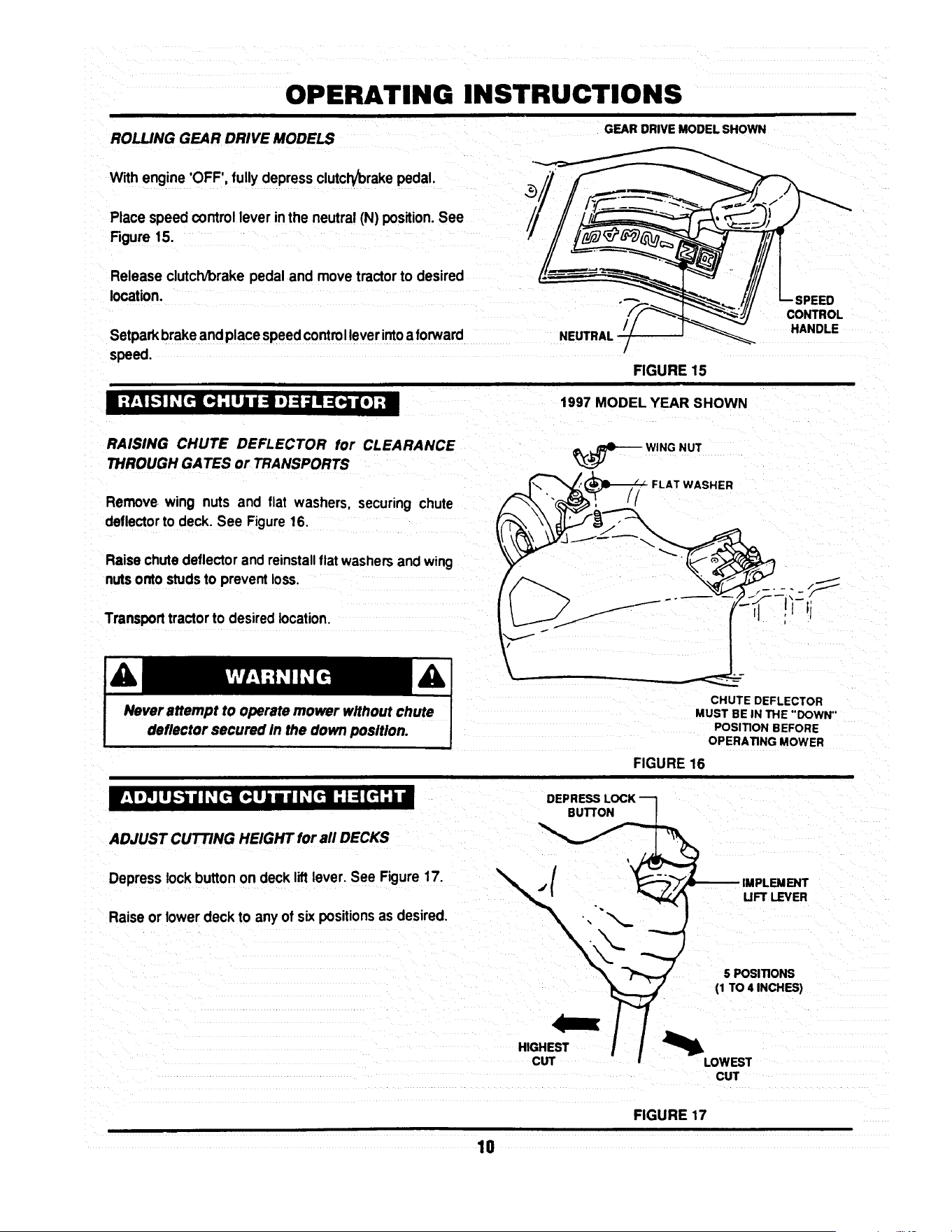
OPERATING INSTRUCTIONS
ROLLING GEAR DRIVE MODELS GEARDRIVEMODELSHOWN
With engine 'OFF', fullydepressclutcl_/brakepedal.
Place speed controllever in the neutral(N) position.See
Figure 15.
Release clutch/brakepedal and movetractorto desired
location.
Setparkbrakeandplacespeedcontrolleverintoaforward
speed.
m:_,_[_1I: [rl_]: t,J=i =1,]=1il _=[,, lo_ia=
/
FIGURE 15
1997 MODEL YEAR SHOWN
-SPEED
CONTROL
HANDLE
RAISING CHUTE DEFLECTOR for CLEARANCE
THROUGH GATES or TRANSPORTS
Remove wing nuts and flat washers, securing chute
deflector to deck. See Figure 16.
Raise chute deflector and reinstall flat washers and wmg
nuts onto studs to prevent loss.
Transport tractor to desired location.
Never attempt to operate mower without chute
deflector secured In the down position.
WING NUT
_,,._ FLAT WASHER
CHUTE DEFLECTOR
MUST BE IN THE "'DOWN"
POSITION BEFORE
OPERATING MOWER
FIGURE 16
i]I o_LuZ,,._dI _(_ub • dI _(_: I _ [_: b •
ADJUST CUTTING HEIGHT for all DECKS
Depresslock button on deck liftlever. See Figure17.
Raiseor lower deck to anyof six positions as desired.
DEPRESS LOCK ---I
( 15.I.oPO::_ON__s,
CUT
FIGURE 17
10

OPERATING INSTRUCTIONS
I / I ",.Z.."_l] _I ;l [*;'i'l I _[rII
For best results,use the followingtips when mowing.
When mowing,cutonly 1/3 of grassheight.Cuttinggrass
deeper couldbe harmfulto your lawn.
If cuttingextremelytall grass, make one cuttingwith the
deck in its highestcuttingposition,then lower deck to
desiredposition and a second cut.
Mow when lawnis dry.
Mow often.Shortergrassclippingsdecomposequicker.
Keep mower blades sharp. A dull blade tearsand shreds
grass instead of cutting. Your SNAPPER dealer can
sharpen blades as required.
Alternate mowing pattern to reduce the possibility of grass
matting.
Mow withenginespeed controlinthe "FAST" positionand
speed controlhandlein a "SLOW" position.
Clean deck, removing all grass clippingsanddebris from
the top and undersideof deck after each use.
V'_ltl'_1!W_.!:] il =f;_*-[*4 =b'_._*]:! I $1
The SNAPPER Series D LAWN TRACTOR can be equipped with a variety of accessories that increase its versatility.
The accessories available for each model are listed in the chart below. Contact an authorized SNAPPER dealer for
ordering any of the accessories desired.
AVAILABLE
ACCESSORIES
Thatcherizer
Dethatcher
Lawn SweeperDethatcher
Lawn Sweeper
Aerator
Broadcast Spreader
Lawn Roller
Snow Blade*
46" DozerBlade SpringTrip****
Dozer Blade Support Kit
2-Stage Snow Thrower**
38" Snow Thrower....
Snow Thrower Support Kit
OPPLT Debris Blower****
Hitch/Subframe Kit
Weight Kit
Tire Chains
Ninja Recycling/Mulch Kit
38 Ninja Recycling/Mulch Kit
38 Wave Recycling/Mulch Kit
Single Bag Catcher***
38" Single Bag Catcher
Dump Cart
Twin Bag Catcher......
38" Twin Bag catcher
Adapter Mounting Kit
Gage Wheel Kit
Utility Trailer
Bag-N-Wagon
Bag-N-Wagon Hitch Kit
LT120G30DB
6-1247
6-1912
6-1914
6-1913
6-1911
6-1916
6-1915
NA
6-1881
NA
NA
6-1880
NA
6-1883
6-1879
NA
NA
6-1254
NA
NA
6-0942
NA
6-0697
NA
NA
6-1334
6-1157
6-1910
NA
NA
NLT120G30DB
6-1247
6-1912
6-1914
6-1913
6-1911
6-1916
6-1915
NA
6-1881
NA
NA
6-1880
NA
6-1883
6-1879
NA
NA
6-1254
NA
NA
6-0942
NA
6-0697
NA
NA
6-1334
6-1910
NA
NA
LT125G38DB
6-1247
6-1912
6-1914
6-1913
6-1911
6-1916
6-1915
NA
6-1881
NA
NA
6-1880
NA
6-1883
6-1879
NA
NA
NA
6-1878
6-1877
6-1886
6-1886
6-0697
NA
6-1888
6-1334
NA
6-1910
NA
NA
LT140H33DBV
LT145H33DBV
6-1247
6-1912
6-1914
6-1913
6-1911
6-1916
6-1915
6-1352
6-1881
6-1370
8-0560
6-1880
6-1371
6-1883
6-1879
6-1245
6-1085
6-1255
NA
NA
6-0943
NA
6-0697
6-0946
NA
6-1334
NA
6-1910
6-0947
6-1308
* Requires Dozer Blade Su;_port Kit .......... ***Requires Adapter Mounting Kit
** Requires Snow Thrower Support Kit ...... ****Requires Hitch/Subframe Kit
11
LT145H38DBV
6-1247
6-1912
6-1914
6-1913
6-1911
6-1916
6-1915
6-1352
6-1881
6-1370
8-0560
6-1880
6-1371
6-1883
6-1879
6-1245
6-1085
NA
6-1878
6-1877
NA
6-1886
6-0697
NA
6-1888
6-1334
NA
6-1910
NA
NA
NLT145H38DBV
6-1247
6-1912
6-1914
6-1913
6-1911
6-1916
6-1915
6-1352
6-1881
6-1370
8-0560
6-1880
6-1371
6-1883
6-1879
6-1245
6-1085
NA
6-1878
6-1877
NA
6-1886
6-0697
NA
6-1888
6-1334
NA
6-1910
NA
NA
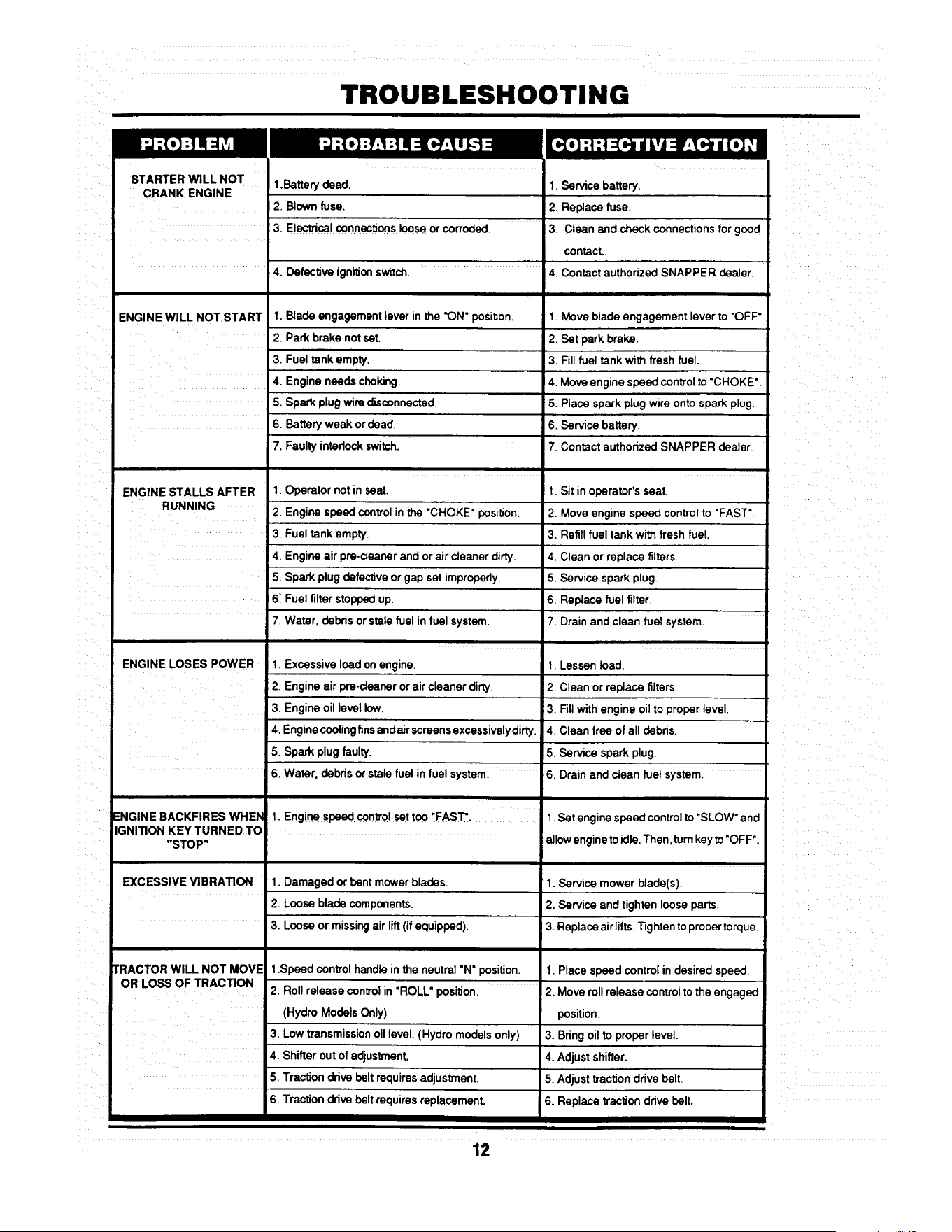
TROUBLESHOOTING
STARTER WiLL NOT
CRANK ENGINE
ENGINE WILL NOT START
1.Battery dead. 1. Service battery.
2. Blown fuse. 2. Replace fuse.
3. Electrical connections loose or corroded. 3. Clean end check connections for good
contact..
4. Defective ignition switch. 4. Contact authonzed SNAPPER dealer.
1. Blade engagement lever in the "ON" position.
I 2. Park brake not set.
3. Fuel tank empty.
4. Engine needs choking.
! 5. Spark plug wire disconnected.
6. Battery weak or dead
7. Faulty intedock switch.
1. Operator not in seat.
2. Engine speed controlinthe "CHOKE" position.
3. Fuel tank empty.
4. Engine air pra-deaner and orair cleaner dirty.
5. Spark plug defective or gap set improperly.
6: Fuel filterstoppedup.
7. Water, debds or stale fuel in fuel system.
1. Excessive load onengine.
2. Engine air pre-deaner or air cleaner dirty.
3. Engineoil level low.
4. Enginecoolingfins end air screens excessivelydirty.
5. Spark plug faulty.
6. Water, debds or stale fuel in fuel system.
ENGINE STALLS AFTER
RUNNING
I
1. Move blade engagement lever to "OFF"
2. Set park brake.
3. Fill fuel tank with fresh fuel.
4. Move engine speed control to "CHOKE"
5. Place spark plug wire onto spark plug.
6. Service battery.
ENGINE LOSES POWER
ENGINE BACKFIRES WHEN
IGNITION KEY TURNED TO
"STOP"
EXCESSIVE VIBRATION 1. Damaged or bent mower blades.
2. Loose blade components.
3. Loose or missing air lift (if equipped).
TRACTOR WILL NOT MOVE
OR LOSS OF TRACTION
3. Low transmissionoil level. (Hydro modelsonly)
4. Shifter out of adjustment.
5. Traction ddve belt requiresadjustment.
6. Traction ddve beltrequires replacement.
7. Contact authorized SNAPPER dealer.
1. Sit in operator's seat.
2. Move engine speed control to "FAST"
3. Refill fuel tank with fresh fue!.
14. Clean or replace filters.
5. Service spark plug.
6. Replace fuel filter.
7. Drain and clean fuel system.
t. Lessen load.
2. Clean or replace filters.
3. Fill with engine oil to proper level.
4. Clean free of all debns.
5. Service spark plug.
6. Drain and clean fuel system.
1. Engine speed control set too "FAST". 1. Set engine speed control to "SLOW" and
allow engine to idle. Then, turn key to "OFF".
1. Service mower blede(s).
2. Service and tighten loose parts.
3. Replace airlifts. Tighten to proper torque.
.Speed control handle in the neutral "N" position. 1. Place speed control in desired speed,
2. Roll release control in "ROLL" Positio n . 2. Move roll release control to the engaged
(Hydro Models Only) position.
3. Bdng oil to proper level.
4. Adjust shifter.
5. Adjust _'action drive belt.
6. Replace tractiondrive belt.
12

TROUBLESHOOTING
BLADE(S) NOT
CUllING
CUTTING GRASS 1.
IMPROPERLY
2.
3.
4.
5.
6.
7,
8.
POOR GRASS 1.
DISCHARGE
1.Blade engagement lever in the "OFF" position.
2, Blade belt requiresadjustment.
3. Blade belt requiresreplacement.
Uneven tire pressure.
Cuing height too low or high.
Engine speed too slow.
Forward speed too fast.
Deck side to side level requires adjustment.
Deck front to rear level requires adjustment.
Blade belt requires adjustment.
Blade belt requires replacement.
Engine speed too slow.
2. Forward speed too fast.
3. Grass is wet.
4 Excessively worn or damaged blade(s).
5. Build-up of grass clippings and debns under deck.
6. Improper blade(s) installed on deck.
7. Blade(s) installed improperly on deck.
BATTERY WILL NOT 1. Poor cable connections.
CHARGE
2. Bad battery cell(s).
OIL LEAKING
FROM TRANSMISSION
1. Move leverto the "ON"position.
2. Adjust mower belt.
3. Replace mowerbelt.
1. Bring to proper pressure.
2. Adjust cuttingheight.
3. Move engine speed oontrol to "FAST'.
4. Move speed controlto a slowerspeed.
5. Adjust side to side level.
6. Adjustfront to rear level.
7. Adjustblade belt tension.
8, Replace blade belt.
1. Move engine speed oontrol to "FAST".
2 Move speed control to a slower speed.
3. Mow when grassis dry.
4.Servicemower blade(s).
5.Cleandeck.
6.InstallproperSNAPPER blades.
7.Installbladesproperly,
I.Cean cablesand batteryterminals.
2. Replace with new battery.
3. Faulty alternator. 3. Contact engine manufacturer's dealer.
1. Loose or missing oil filler cap. (Hydro Models Only) 1. Check oil level and replace oil cap.
2. Leaking axle seals. 2. Contact authorized SNAPPER dealer.
3. Leaking at casing seal 3. Contact authorized SNAPPER dealer.
13

MAINTENANCE INSTRUCTIONS
SUBJECT
Engine
Engine
Engine
Air Pre-Cleaner
Air Cleaner
Spark Plug
Fuel Filter
Engine Cooling
System
Battery
Tires
Drive Belts
Mower Blades
Mower Deck
Mower
Deck
Lubrication
Points
Hydrostatic
Trans. Oil
SERVICE
TO BE PERFORMED
Check Oil Level
Initial Oil Change
Periodic Oil Change
Service Sponge Pre-
Cleaner Element
Replace Element
Replace Plugs
Replace Filter
Clean Shrouds & Fins
Check Electrolyte
Charge Battery
Check Pressures
Check For Wear And
Tension
Check For Wear And
Damage
Clean Debris
Accumulation
Clean Outside and
Underside
Grease or Oil
Check Oil Level
REFERENCE EACH 5 25 50 100 EACH
PAGES USE HOURS HOURS HOURS HOURS SEASON
Page 6 X
Pages 15 & 16 X
page 15 X*
Engine Manual X**
&Page 19
Engine X**
Manual.
Engine X
Manual.
Page 19 X
Engine Manual X**
& Page 20
Page 20 X X
Page 20 & 21 X
Page 6 X X
Pages 22-26 X X
Pages 20-21 X
i
Page 6 X X X
Page 6 X X X
Pages 17 &:18 X X
Page 15 X
*Change oil every 25 hours when operating under heavy load or high temperatures.
**Clean more often under dusty conditions or when air debris is present
TRACTOR
MODEL No.
LT120G30DB, NLT120G30DB
LTI25G33DB
LT140H33DBV, LT145H33DBV
LT125G38DB
LT145H38DBV, NLT145H38DBV
DRIVE BELTS
Engine to Transmission Engine to Deck Standard
2-8585 2-8793 1-8069
2-8585 2-9205 3-4168
2-8585 2-9205 3-4168
2-8585 3-5500 4-2998
2-8585 3-5500 4-2998
MOWER BLADES
NINJA
2-6597
2-4234
2-4234
14

MAINTENANCE INSTRUCTIONS
The hydrostictransmission does not normally require
maintainence,however,properoillevelshouldbeverified
sfter everyseason.
TO CHECK OIL LEVEL IN TRANSMISSION
Remove seat by removing seat adjustment knobs, See
Figure 18.
Lay seat forward. Be careful notto pullseatswitchwires
from the switch.
Disconnectnegative (black) battery wire from terminal
first!See Figure 19.
Disconnectpositive(red) battery wire from terminal last!
Remove batteryand battery tray. Transmissionis now
accessible.
\
REINSTALL
BATTERY
PER DECAL
\
FIGURE 18
SEAT
ADJUSTING
KNOBS
Clean any debris off of oil cap and top cover before
removiing fill cap. See Figure 20.
Before attempting any adjustments or repairs, STOP
the engine, remove the key, remove the spark plug
wire(s) from the spark plug(s) and secure wire(s)
away from plug(s).
Visuallycheck oil level.
Oillevelshouldbe approximately3/4" (+1/4")from topof
case. Ifthe level is lowerthan 3/4",add 10W30 motoroil
to bringthe levelup as required.
Replacefillcap.
Reinstallbattery tray.
NEGATIVE (-)
TERMINAL
(BLACK)
FIGURE 19
POSITIVE(÷)
TERMINAL
(RED)
Reinstall battery. See Figure 19.
Reinstalland adjust seat. See Figure18.
- 3/4" +1/4"
FIGURE 20
15

MAINTENANCE INSTRUCTIONS
MODELS L T120G30DB, NL T120G30DB,
LT125G33DB & LT125G38DB
These models are equipped with 12 & 12 1/2 hp engines
which are furnishes with extended oil drains. See Figure
21.
Raisetractorhood and tilt itforward.
Disconnectsparkplugwire. Securewire awayfrom soark
plug.
Put a brick or block of wood under deck wheel on opposite
side of oil drain.
Loosenoilfill cap on engine.
Placea 2 quart capacityflat containerbeneath end of oil
drain.
Removeoil plug.
Allowengineoilto drain completely.
After alloilhas drained, replace oilplugand fill enginewith
new motor oil as specifiedin Engine Owner's Manual.
MODELS LT140H33DBV, LT145H38DBV &
NL T145H38DB V
These models are equipped with 14 & 14 1/2 hp
engineswhichare furnished withFastexTM oildrains.See
Figure22.
Rotate drain body counterclockwise and pull out to open
drain.
Drainoil into a 2 quart container placed beneath end of oil
drain.
After all oil has drained, push drain body "IN" and rotate
clockwiseto close. Push drain cover over drain nipple.
Fill engine with new motor oil as specified in Engine
Owner's Manual.
NOTE:
Ifthetractor's engine is equipped withan oil filter, change
at everyoil change.Contactengine manufacturerdealer
for replacementfilter for particularengine.
ROTATE
CLOCKWISE AND
PULL OUT TO OPEN
16
FILLER
TUBE
OIL DRAIN
EXTENSION
\
FIGURE 21
FIGURE 22
PLUG
TO DRAIN OIL
L FILLER
TUBE
/
FASTEX'_
OIL DRAIN

MAINTENANCE INSTRUCTIONS
The followinglubricationpoints shouldbe servicedafter
each 25 operating hours to insure optimum performance
of the Series D Lawn Tractor.
FRONT WHEEL BEARINGS
Lubricateeach front wheel bearing through the grease
fitting on wheel hub. Using general purposegrease in a
greasegun, addgrease untilgreasepurgesfrom bearing.
See Figure 23.
AXLE SPINDLE
LUB RICATION
FITTING
AXLE SPINDLES
Lubricateeach axlespindlewith 1 shot ofgeneral purpose
grease. See Figure 23.
NOTE:
The R.H. spindle fitting faces forward and the L,H. spindle
fitting faces to the rear.
FRONT WHEEL BEARING
LUBRICATION FITTING
FIGURE 23
CLUTCH/BRAKE
PIVOT LUBRICATION
RTTING
CLUTCH//BRAKE PIVOT
The clutch/brake pivot is located on the L.H. underside of
the tractor and is lubricated with one shot of general
purpose grease. See Figure 24.
STEERING SECTOR GEAR
Lubricatewith a lightcoat of 30 wt. motoroil.See Figure
25.
STEERING SHAFT
Lubricatesteeringshaft wear pointswitha light coatof 30
wt. motoroil.
FIGURE 24
FUEL TANK
STEERING
SECTOR
SECTOR
GEAR
j"
17
FIGURE 25

MAINTENANCE INSTRUCTIONS
STEERING DRAG LINK
Lubricateboth ends of steering drag link with a small
amountof 30 wt. motoroilfrom anoilcan. See Figure26.
STEERING TIE ROD
Usingan oil can,filledwith30wt. motoroil, lubricateboth
endsof steeringtie rod. See Figure27.
BLADE ENGAGEMENT MECHANISM
Using30 wt. motor oil, lubricatethe blade engagement
mechanismpivot points,which are locatedon the R.H.
undersideof tractor.See Figure28.
PARK BRAKE LATCH
Using 30 wt. motor oil, lubricatethe park brake latch
mechanismpivot points, which are located on the L.H
undersideof tractor.See Figure29.
DECK LIFT MECHANISM
Lubricateallwear and pivotpoints ofthe deck liftmecha-
nismwith a thincoat of 30 wt. motor oil.
DRAG UNK
LUBRICATION
FIGURE 26
::::C'o:
FIGURE 27
LUBRICATE
COMPONENTS ON
UNDERSIDE
OF TRACTOR
".BLADE ENGAGEMENT
\
LEVER
FIGURE 28
PARK BRAKE
LATCH
LUBRICATE
COMPONENTS ON
UNDERSIDE
OF TRACTOR._
FIGURE 29
18

MAINTENANCE INSTRUCTIONS
The componentslistedshouldbe servicedon a regular
basisto insurethattheyare intopworkingcondition.Refer
to SERVICE SCHEDULE on Page 14 for recommended
serviceintervals.
AIR CLEANER
ENGINE AIR PRE-CLEANER
Theengineairpre-cleanershouldbe removedandcleaned
every25 operatinghours.See Figure30. Referto Engine
Owner'sManual for specificcleaninginstructions.
ENGINE AIR CLEANER
The engine air cleaner element shouldbe removedand
replacedevery 25 operatinghours.See Figure30. Con-
tactenginemanufacturer'sdealerfor correctreplacement
element.
ENGINE
AIR PRE.CLEANER
\
\
FIGURE 30
FUEL
TANK
SPARK PLUG
Removeand replaceenginesparkplugafter 100 operat-
ing hours. Refer to EngineOwner's Manual for correct
replacementplugand gap specifications.
FUEL FILTER
Theenginefuelfiltershouldbe replaced every100 oper-
atinghours.Remove the fuel filter as follows:
NOTE:
Itmay be necessary to drainthe fuel tank before removing
fuel filter to preventexcessivespillageof gasoline.
HOSE CLAMR
Raisetractorhood.
Removesparkplugwire(s)andsecureawayfrom plug(s).
Locate fuel filter. Remove hose clamps and fuel hoses
from bothsides of fuel filter. See Figure31.
NEW FUEL FII
PART No. 1-4359
FIGURE 31
Installnew fuel filtei"part number1°4359. See Figure32,
Fillfueltankwith freshgasoline.Refer to EngineOwner's
Manualforfuel specifications.
Reconnectsparkplugwire(s).
FIGURE 32
Lowertractor hood.
19
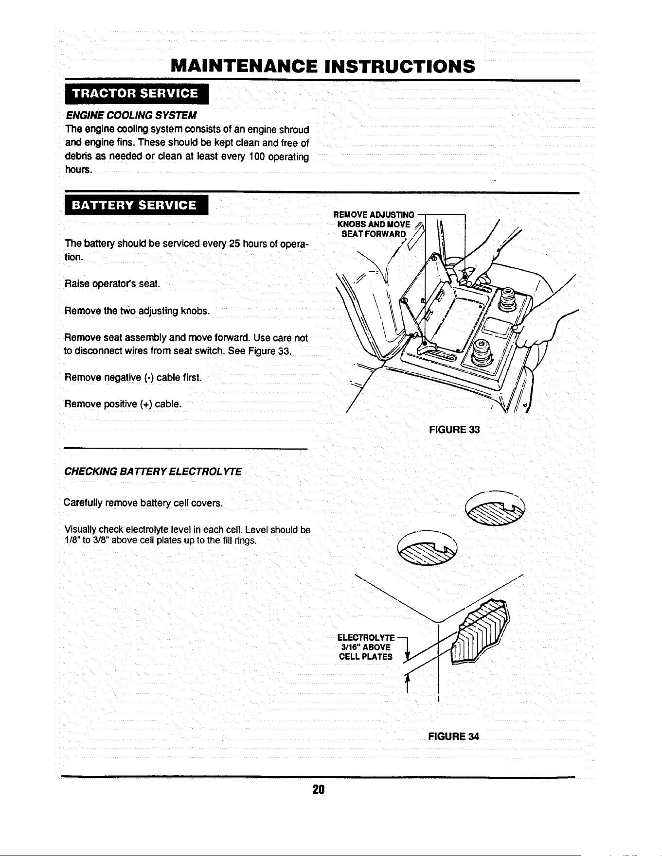
MAINTENANCE INSTRUCTIONS
ENGINE COOLING SYSTEM
The engine coolingsystemconsists of an engineshroud
and engine fins.These shouldbe kept clean and free of
debrisas needed or clean at least every 100 operating
houm.
The batteryshouldbe servicedevery25 hours of opera-
tion.
Raiseoperator'sseat.
Removethe two adjustingknobs.
Remove seat assemblyand moveforward.Use care not
to disconnectwiresfrom seat switch.See Figure33.
Removenegative(-) cable first.
Removepositive(+) cable.
REMOVE ADJUSTING
KNOBS AND MOVE _ / --
S ,TFO.WA.0, I / ,7
f
FIGURE 33
CHECKING BATTERY ELECTROLYTE
Carefully remove battery cell covers.
Visually check electrolyte level in each cell. Level shouldbe
1/8" to 3/8" above cell plates up to the fill rings.
ELECTROLYTE
3116" ABOVE
CELL PLATES
FIGURE 34
2O

MAINTENANCE INSTRUCTIONS
Usingdistilledwater, fill cells as needed to 1/8" to 3/8"
above cell plates.
Replace cell covers.
Charge battery if required.
Install positive(+) cable first.
Install negative(-) cable last.
Install seat assembly over battery and secure in position
with adjusting knobs. Leave knobs loose.
Lower operator's seat and adjust to desired position.
Raise seat and tighten adjusting knobs.
BATTERY CHARGING
The engine is equipped with a flywheel alternator to
charge the battery. If the tractor is not run regularly,
connect the battery to a charger monthlyto maintainthe
specific gravity at 1.250 or higher. If this reading falls
below 1.175, the batteryliquidmay freeze whentempera-
turesdropto around zero degrees F. To charge, connect
perinstructionsfumishedwithcharger,If time allows, slow
charge at 1 amp for ten hours, or as an alternate, fast
charge at 3 amps forfour hours. Observe all precautions
while charging.
.LEY
TRACTION DR! VE-BEL T
Check the tractiondrivebeltfordamage andwear after25
operatinghours. The traction drive belt is locatedon the
undersideofthe tractorandspansfromthe enginepulley's
top groove to the transmissionpulley. See Figure 35.
TRACTION --
DRIVE BELT
FIGURE 35
21

MAINTENANCE INSTRUCTIONS
Should the tractiondrive belt show signs of excessive
wear or damage, replace.
MOWER DECK REMOVAL
Placetractoron a firm,levelsurfacesuchasadrivewayor
garage floor and engage park brake.
Turnengine "OFF".
Raise hoodand removesparkplugwirefromsparkplug.
Securesparkplugwireawayfromsparkplug.See Figure
36.
\
UFT ROD
FRONT
UFT ARM
FIGURE 37
HAIR PIN
Lowerdeck to lowestsetting.
Disconnectdeck liftrodfromfrontliftarm. See Figure37
Removehair pinsfromfrontdeckhangerrod.See Figure
38.
RIGHT
SIDE
LO;T
Turnwheelsto the left, k'-,
Hold front of deck"UP"andslidefrontdeckhangerrodto ""'_%_- "'_
the right and out. FRONT DECK /"f_ _.._/_/_
HANOERROO/
Lowerfront of deck to ground. /
FRONT
Remove hair pin and flat washerfrom reardeck hanger LIFT HAIRPIN
bracket on bothsidesof tractor.See Figure39. ARM
FIGURE 38
SECURE WIRE
AWAYFROMPLUG ! t_
I
S
FIGURE 38
__.//_ SECTOR I
PIN AND WASHER_ _. ,
FROM BOTH _ /
../_.._.TO R PLATES "_' _.__L_
FIGURE 39
22

MAINTENANCE INSTRUCTIONS
Make note of hole used in sector plate.
Slide sectorplates off of rear deck hanger brackets.
Slide deck forward.
Remove deck drive beItfrom engine pulley bottom groove.
See Figure 40.
Slidedeck back and disconnect springfrom tension idler.
Pull deck from under tractor from R.H. side.
TRACTION DRIVE BELT REMOVAL
Remove two belt guide mounting bolts from each side of
tractor frame. See Figure 41.
Slide belt guide assembly to the rear and remove.
Disconnect traction belt idler pulley spring from tractor
frame. See Figure 42.
Loosen mounting nuts on traction drive belt tension and
stationary idlers just enough to allow belt to clear belt
guides. See Figure 43.
(30" & 33" BELT GUIDES SHOWN)
FIGURE 40
FIGURE 41
RIGHT REAR
TRACTOR FRAME
FIGURE 42
_I'ATIONARY------1 I-_1 _ LOO6EN
II I
IDLER
FIGURE 43
23

MAINTENANCE INSTRUCTIONS
Removetractiondrivebeltfromenginepulleytop groove.
See Figure44.
Removebelt from centerbeltguide.
Pullbelt untilitcan be removedfrom transmissionpulley.
TRACTION DRIVE BELT REPLACEMENT
Place new traction drive belt over transmission pulley and
span to engine pulley.
Place belt intotop grooveof enginepulley.
REMOVE
FROM PULLEY
Route belt through stationary and tension idlers. See
Figure45.
FIGURE 44
PULLEY
NOTE:
When installing new belt, make certain the stationary idler
is mounted in the hole closest to the L.H. side of the tractor.
See Figure 45. (See Page 29 for Belt Adjustment)
Make certainbelt is withinbeltguidesof idlers.
Attachtensionidlerspringtotractorframe. See Figure46,
Reinstall mower deck in reverse order of removal.
TENSION
IDLER
STATIONARY
IDLER
STATIONARY
IDLER
BRACKET
DE
I
RIGHT REAR
TRACTOR FRAME
STATIONARY
IDLER
FIGURE 45
\
\
!CTSPRING
TO FRAME
FIGURE 46
24
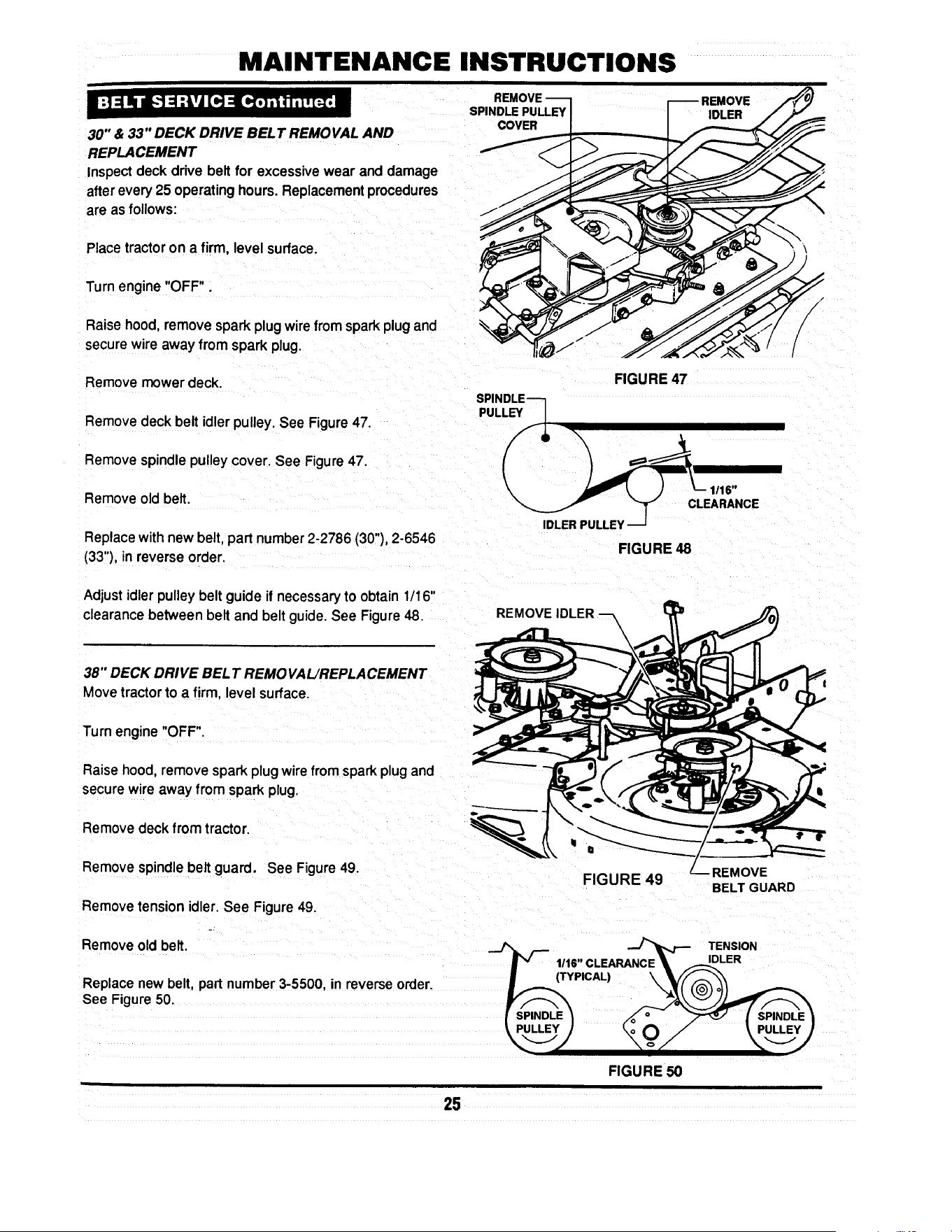
MAINTENANCE INSTRUCTIONS
30" & 33" DECK DRIVE BELT REMOVAL AND
REPLACEMENT
Inspect deck drive belt for excessive wear and damage
after every 25 operating hours. Replacement procedures
are as follows:
SPINDLE PULLEY
COVER
REMOVE
IDLER
Place tractoron a firm, level surface.
Turn engine "OFF".
Raise hood, remove spark plug wire from spark plug and
secure wire away from spark plug.
Remove mower deck.
Remove deck belt idler pulley. See Figure 47.
Remove spindle pulley cover. See Figure 47.
Remove old belt.
Replace with new belt, part number 2-2786 (30"), 2-6546
(33"), in reverse order.
/
/
FIGURE 47
SPINDLE----]
PULLEYFq L
IDLERPULLEY
FIGURE 48
Adjustidler pulley belt guide if necessary to obtain 1/16"
clearance between belt and belt guide. See Figure 48.
REMOVE IDLER ---_
38" DECK DRIVE BEL T REMOVAL/REPLACEMENT
Movetractorto a firm, levelsurface.
Turn engine "OFF".
Raise hood, remove spark plug wire from spark plug and
secure wnreaway from spark plug.
Remove deck from tractor.
Remove spindle belt guard. See Figure 49.
Remove tension idler. See Figure 49.
FIGURE 49
BELT GUARD
Remove old belt. _ ,__ . _ TENSION
p' 1,1,c,E, .cE\
Replace new belt, part number 3-5500, in reverse order. I.,_ (TYP'cAL) k_y(F_-'_o_
See Fngure 50 _pupl_ _ __._
FIGURE 50
25

MAINTENANCE INSTRUCTIONS
" W.ARNING " A I
Blades are extremely sharp and can cause severe I
injury. Wear heavy leather gloves when handling or I
working around blades. DO NOT use a blade that is I
excessively worn or damaged. I
_Ib WARNING --_
I Never use a cutting blade that shows signs oq
excessive wear or damage. Refer to Figure 4.5. Wear I
heavy leather gloves when handling or working I
around cutting blades. Blades are extremely sharPl
and can cause severe injury. I
STANDARD BLADE WEAR LIMITS
All mowerblades shouldbe checked for excessivewear
anddamage before each use.See Figure52.
30" &33"MOWER BLADEREMOVAL/REPLACEMENT
Movetractorto a firm, levelsurface.
Turn engine "OFF".
-_ -_ _ B- WEARUMIT
__ CUTTINGEDGE
-_.._ WORN
_--- C- DANGEROUSCONDITIONI
DO NOT USEON MOWERI
FIGURE 52
I11
Raise hood, remove spark plug wire from spark plug and r-_ NUT BLADE-JJ-_ ./1
secure wire away from spark plug. 1 _-FF-'-LOCK WASHER I/I _ I
e ove eo ,ro traOor.
Install new 30" blade, pad number 1-8069, or 3-4168 for _J/ "_/
33" blade mounting bar. v__
BLADEMOUNTINGBOLTS
FIGURE 53
28

MAINTENANCE INSTRUCTIONS
Install blade mounting bolts, internal tooth lock washers
and nuts. See Figure 53
Torque blade to 30 to 40 Ft, Lbs.
38" STANDARD MOWER BLADE REMOVAL AND
REPLACEMENT
Move tractor to a firm, level surface.
Turn engine "OFF".
Raise hood, remove spark plug wire from spark plug and
secure wire away from plug.
Remove mowing deck from tractor.
Carefully position deck to access blades.
Remove blade mounting nut and cone washer from each
blade. See Figure 54.
Install new blades, part number 4-2998.
Secure blades with cone washers and mounting nuts. See
Figure 54.
Torque blade to 70 to 80 Ft Lbs.
(2- REQUIRED)
CONE
I WASHER
_ MOUNTING NUT
FIGURE 54
27
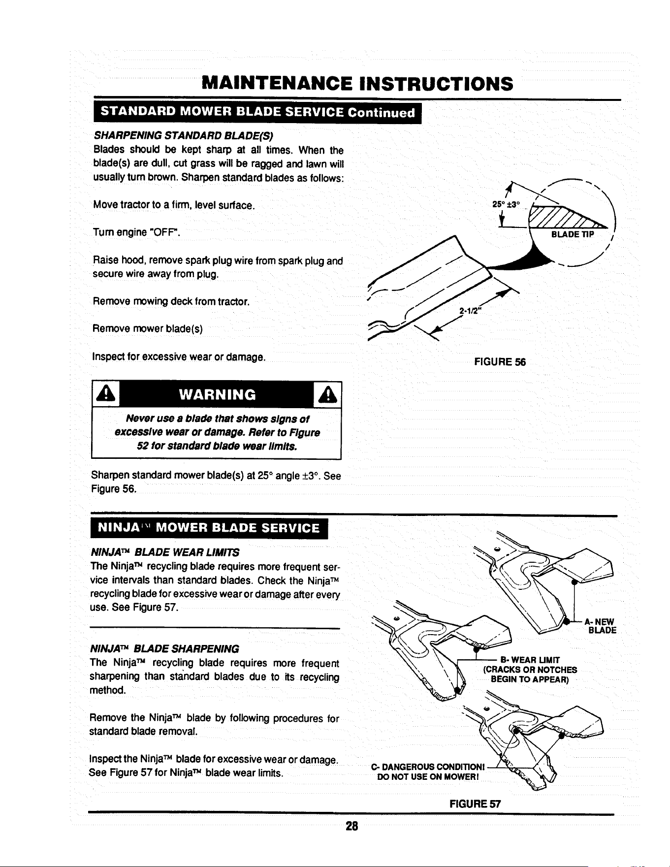
MAINTENANCE INSTRUCTIONS
SHARPENING STANDARD BLADE(S)
Blades should be kept sharp at all times. When the
blade(s) are dull, cut grass will be ragged and lawn will
usuallyturn brown.Sharpen standardbladesas follows:
Movetractorto a firm, levelsurface.
Tum engine "OFF'.
Raise hood,removesparkplugwirefromsparkplugand
securewire away from plug.
Remove mowing deck fromtractor.
Remove mower blade(s)
Inspectfor excessivewear or damage.
FIGURE 56
Never use a blade that shows signs of
exceaslve wear or damage. Refer to Figure
52 for standard blade wear limits.
Sharpenstandardmowerblade(s) at 25° angle+3°. See
Figure 56.
NINJATM BLADE WEAR LIMITS
The NinjaTM recyclingblade requiresmorefrequentser-
vice intervalsthan standardblades. Check the NinjaTM
recyclingblade for excessivewear or damageafterevery
use. See Figure 57.
NINJATM BLADE SHARPENING
The NinjaTM recycling blade requires more frequent
sharpening than standard blades due to its recycling
method.
Remove the NinjaTM blade by followingproceduresfor
standardblade removal.
Inspectthe NinjaTM bladefor excessivewear or damage.
See Figure57 for NinjaTM bladewear limits,
B- WEAR UMIT
(CRACKS OR NOTCHES
BEGIN TO APPEAR)
_ DANGEROUS CONDITIONI / _2._ ._,' 'It
DO NOT USE ON MOWERI "_ "_ _
FIGURE 57
28

MAINTENANCE INSTRUCTIONS
Never use a blade that shows signs of
excessive wear or damage. Refer to Figure
57 for NinJaTM blade wear limits.
Sharpen allcuttingedges ofthe NinjaTM recycling blade at
27° (+3°, -2 °) for optimum performance. See Figure 58.
Reinstall sharpened NinjaTM blade in reverse order of
removal.
Torque mounting bolts or nuts to proper standard blade
torque value for deck being serviced.
BLADE
FIGURE 58
Should a gradual loss of traction be noticed, it may be
necessary to adjust the traction drive belt tension. Adjust
as follows:
BELT
BRACKET
MORE
Movetractor to a firm, level surface.
Turn engine "OFF".
Raise hood remove spark plug wire from spark plug and
secure wire away from plug.
Remove mowing deck.
Remove the traction drive belt stationary idler mounting
bolt. See Figure 59.
Move the stationary idler one hole toward right side of
tractor for more tension.
NOTE:
Note the orientation of belt guide and make certain it
remainsin the same orientationafter moving idler.
NOTE:
Should less tension be required move stationaryidler
towardsright side of tractor. See Figure59.
|
IDLER
STATIONARY
MOUNTING BOLT
LESS
BELT GUIDE-
MAKE CERTAIN BELT
GUIDE ORIENTATION
IS MAINTAINED.
I
÷
STATIONARY
IDLER
MOUNTING BOLT
FIGURE 59
29

MAINTENANCE INSTRUCTIONS
Securestationaryidlerwith mountingbolt.
Place sparkplug wire onto spark plug.
Setpark brake.
Start Engine.
Visuallyinspecttractiondrive beltfor movement.
When properlyadjusted,the tractiondrivebelt shouldnot
have any movement or rotationwith the engine running
and park brake engaged.
Shouldmovement be present,readjusttractiondrive belt
to releasebeittension asdescribedinpreviousinstructions.
Movetractorto a firm, levelsurface. /
Turn engine"OFF'.
Raisehood,remove sparkplug wirefrom sparkplug and
securewire away fromplug.
Movebladeengagement leverdownto"OFF".See Figure ._._:
60. -::
E
ENGAGEMENT
TO "OFF"
Lower deckto lowest cutting position
Checkfrontto rear level.
If deck front to rear level is not correct,
thiscouldcause blade beltproblems.
30" & 33" DECKS
Measure length of blade cable extensionspring. See
Figure61.
Moveblade engagement lever to "ON".
Measure blade cable extension spring.Spring should
extend1"+_1/8"for properbelttension.See Figure61.
EXTENSION SPRING
FIGURE 60
FIGURE 61
3O

MAINTENANCE INSTRUCTIONS
To adjust tension, remove extension rod mountingbolt
and nut. See Figure62.
Move extension rodto next hole towards rear of deck and
securewith mountingbolt and nut. MOUNTING-
NUT & BOLT
Measure extension spring with blade engagement lever in
the "ON" and "OFF" positions. See Figure 61. Continue
adjustment until tension is correct.
I
-_LEAST TENSION/d
• _L / MOSTTENSlON
"-_ //
FIGURE 62
NOTE:
Before adjusting deck, bring tire pressureto properpsi.
Front12 psi, Rear 10 psi.
SIDE TO SIDE LEVEL
Movetractorto a firm, level surface.
Turn engine "OFF".
Raisehood, remove spark plugwire from spark plug and
securewire away from plug.
Move blade engagement lever to "OFF".
Place a piece of angle iron under center rear of deck.
SECTOR
PLATE
__ REMOV_ _
Remove hair pins and washers securing rear of deck to
sector plates. See Figure 65.
FIGURE 65
31

MAINTENANCE INSTRUCTIONS
Slidesectoroffof pinsandcarefullylowerdeckontoangle
iron.
33" DECK SHOWN
Rotate.blade(s) untilblade tipsare at each sideof deck.
•Measuredistancefrom blade tipto flooron each sideof LMEASUREFROM
deck. BLADE TIPS
TO FLOOR
Bladetips shouldbe within1/8"ofeach otherfor thedeck
to be consideredlevel. See Figure66.
If measurementdiffersmore than 1/8",adjustas follows:
Loosenfrontliftarm pivotboltonfrontof rightsiderail.See
Figure67.
NOTE:
The 38" deck does not incorporatea pivotbolt.
PIVOT BOLT
LOOSEN
SHOULDER BOLT
_-_ ANGLE IRON
FIGURE 66
f
Looseneccentricshoulderbolt. See Figure67.
Turneccentric"UP"or'DOWN" as requiredto leveldeck.
See Figure67.
Tighteneccentricshoulderbolt.
Tighten pivotbolt.
J
ECCENTRIC
AS REQUIRED
FIGURE 67
Place sector plates back onto rear lift arms and secure
withwashersand hairpins. SECTORPLATES
Make certainsector plates are mountedin the same _---_,,, ,,__ _;¢__ ________
holeson each side forproper frontto rearlevel.
FRONT TO REAR LEVEL-SECTOR PLATES --_-- "_-_
LOWEST OE
Removehairpinsand washerssecuringsectorplatesto
rearliftarms.See Figure 68. _ ~ _DECI(-S'_ING _ -------_-SETTING
Movesectorplate as requiredto raiseorlowerdeck. ___.-__ .)_1--'_ I_11_1_
DECK
REMOVE'
HAIR PIN & WASHER
FIGURE 68
32

MAINTENANCE INSTRUCTIONS
NOTE:
Thedeck shouldbe set sothat the rearofthe deck is 1/4"
lowerthan the front.See Figure69.
FRONT
X • 1/4"
33" DECK SHOWN
P'/////;! REAR
FRONT TO REAR LEVEL- FRONT LIFT ROD
If the sector plates are in their lowest setting and proper L__ MEASUREFROM
level cannot be obtained, adjust the front liftrod as follows: BLADETIPSTOFLOOR
x
f
FIGURE 69
Movedeck lift leverto #5 position.
30" & 33" DECK
Place a 2X4 woodenblockon edge underfrontcenter of
deck.
Place a 3X3 wooden blockunder rearcenter of deck.
NUT
/
/
Remove hair pins and washers securingsectorplates.
Lowerrear of deck onto3X3 block. See Figure68.
Removehairpinand washer securingfrontliftrodtofront
liftarm. See Figure 70.
Removefront lift rod andcarefullyrestfrontof deckonto
2X4 block.
Loosenjam nuton front liftrod.See Figure70.
•HAIR PIN
_ FRONT UFT ROD
FIGURE 70
Turnfrontliftrodhangerblockuntilitcan be reinstalledinto
frontlift arm withoutliftingdeck. See Figure70.
Secure lift rodto liftarm withwasher and hair pin.
Placesector platesonto rearhanger bracketsandsecure
withwashers and hair pins.
Raisedeck and remove wooden blocks.
Repeat steps for frontto rear level adjustment.Referto
FRONT TO REAR LEVEL- SECTOR PLATESo
Make certainsector plates are mountedin the same I
holes on each sidefor proper front to rear level. I
33

MAINTENANCE INSTRUCTIONS
NOTE:
Before adjusting deck, bring tire pressureto proper psi.
Front 12 psi, Rear 10 psi.
SIDE TO SIDE LEVEL
FRONT OF TRACTOR
BLOCK
Move tractor to a firm, level surface.
Turn engine "OFF".
Raise hood, remove spark plug wire from spark
plug and secure wire away from plug.
Move blade engagement lever to "OFF".
Place a 2-112" tall block under the front of the deck
centered between the front lift arms. See Fig 70a.
Place a 1-3/4" tall block under the rear of the
deck in the center. See Fig 70a.
Position the blades as shown in Fig 70a and lower
the deck onto the blocks.
1-3/4"TALLBLOCK_--_
FIGURE 70a
BLADESORIENTATEDFORSIDE-TO-SIDELEVELCHECK
38" DECK
Disconnect the front lift rod and the rear hanger
plates. See Fig 68 on page 32 and Fig 70b.
NUT
Put the lift lever in the 3rd position from low cut.
Measure the distance from each blade tip to the
floor. The measurements should be within 1/8"
of each other. (Factory setting)
If the difference is less than 1/8", go to next
section, Front-to-rear level.
If the difference is more than 1/8", adjust as
described in the following steps.
FRONT UFT
FIGURE 70b
Loosen the front adjuster nut until adjuster
moves freely. Then, tighten the nut until the
adjuster moves only when moderate force is
applied to one side of the deck. See Fig. 70c.
Adjust the side-to-side level of the blade tips by
moving one side of the deck up or down as
needed to obtain 118" or less side-to-side deck
level.
After leveling deck, re-tighten the adjuster nut
to from 30 to 40 ft-lbs.
FIGURE 70c
\
_ADJUSTER
NUT
33A
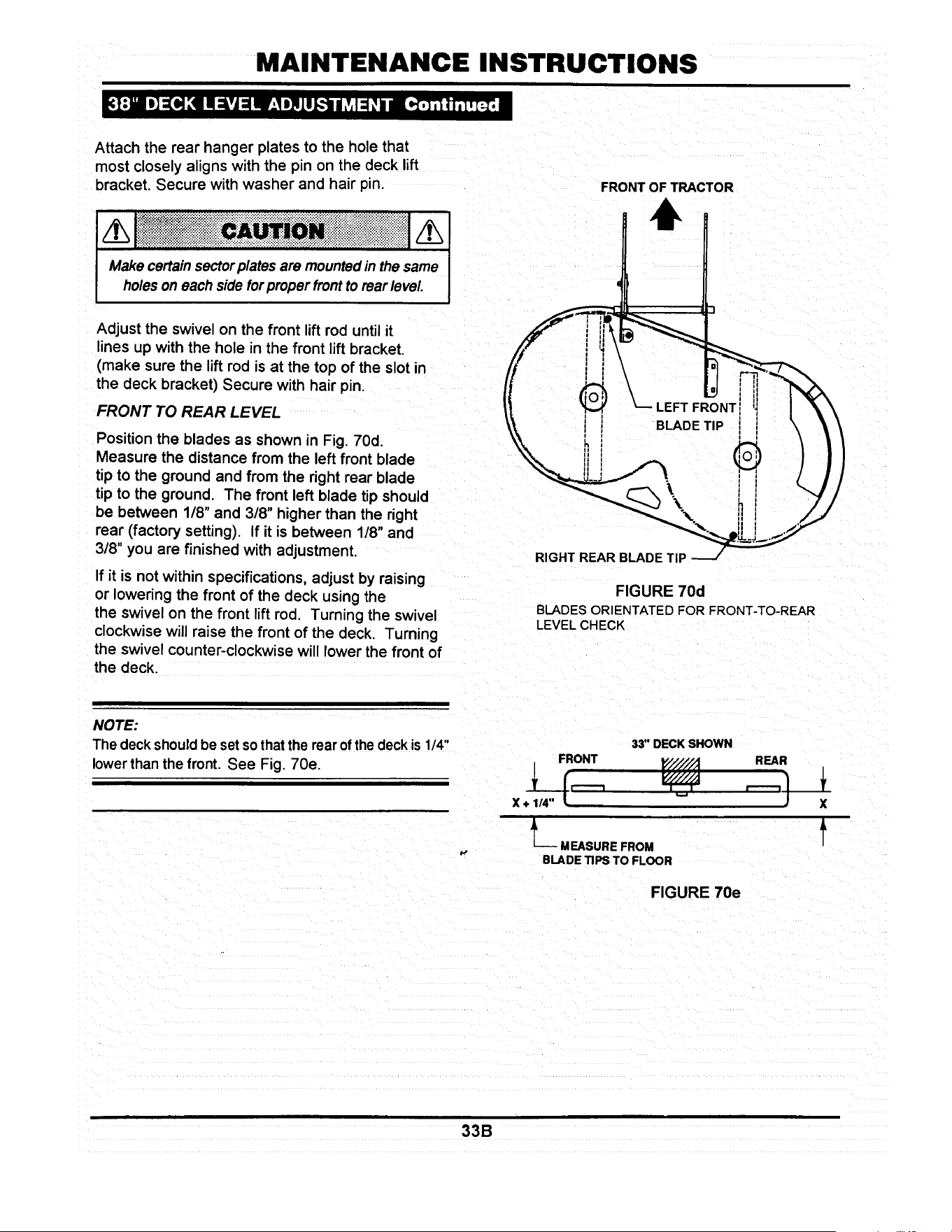
MAINTENANCE INSTRUCTIONS
Attach the rear hanger plates to the hole that
most closely aligns with the pin on the deck lift
bracket. Secure with washer and hair pin.
/h[ i !! !!ii! iiiii!i i ii! !i!!!i! !i Iiiiic i! !i ! Ni i ii!i Mii iii iii ii i i i i i i iiiiiiiiiiiiiii!j/hi
Make certain sectorplatesare mountedin the same I
holes on each side for proper frontto rear level J
FRONT OF TRACTOR
Adjust the swivel on the front lift rod until it
lines up with the hole in the front lift bracket.
(make sure the lift rod is at the top of the slot in
the deck bracket) Secure with hair pin.
FRONT TO REAR LEVEL
Position the blades as shown in Fig. 70d.
Measure the distance from the left front blade
tip to the ground and from the right rear blade
tip to the ground. The front left blade tip should
be between 1/8" and 3/8" higher than the right
rear (factory setting). If it is between 1/8" and
3/8" you are finished with adjustment.
If it is not within specifications, adjust by raising
or lowering the front of the deck using the
the swivel on the front lift rod. Turning the swivel
clockwise will raise the front of the deck. Turning
the swivel counter-clockwise will lower the front of
the deck.
BLADE TIP
\
\
RIGHT REAR BLADE TIP
FIGURE 70d
BLADESORIENTATEDFORFRONT-TO-REAR
LEVELCHECK
NOTE:
The deck should be set sothat the rear of the deck is 1/4"
lowerthan the front. See Fig. 70e.
33" DECK SHOWN
FRONT
JL MEASURE FROM
BLADE TIPS TO FLOOR
REAR
FIGURE 70e
X
f
33B

MAINTENANCE INSTRUCTIONS
STEERING SECTOR
Should excessive "PLAY" be present in the steering,
adjustas follows:
Tum Engine"OFF" and raise tractorhood.
Removespark plugwire from spark plug and securewire
away from plug.
From leftside of tractor,locatethe steeringsectorbelow
fuel tank. See Figure 71.
Looseneccentricmounting nut.
Rotate eccentric clockwise until steering "PLAY" is re-
duced.See Figure 71.
Tighteneccentricmounting nut.
Replacespark plugwire onto sparkplugand lowerhood.
FIGURE 71
If movement of tractor does not correspond with the
selectedspeedonshiftquadrant,adjustthe speedcontrol
lever as follows:
Withengine running,drivetractor and move shiftleverto
locateneutral.
Turn engine "OFF".
Raise hood,remove sparkplugwire fromsparkplugand
securewire away from plug.
Locate speed control lever mount behind right rear tire.
See Figure72.
Loosenmountingnuts.
Movethe speed controlleveruntilit is indirectrelationto
the neutral"N"position on quadrant. See Figure 73.
Tighten mounting nuts.
SPEED CONTROL
LEVER MOUNT
ED
CONTROL
LEVER
®
MOUNTING (_
NUTS
FIGURE 72
SPEED CONTROL LEVER
MOVE TO NEUTRAL
(N) POSITION
FIGURE 73
34

MAINTENANCE INSTRUCTIONS
HYDRO DRIVE MODELS
To be properlyadjusted,the brake shouldstopthe tractor
inapproximately6 feet from top speed when the clutch/
brake pedal is fully depressed.
Adjustbrake when necessary as follows:
Turnengine "OFF'.
Raise hood, remove spark plugwire fromsparkplugand
securewire away from plug.
Locatebrake adjustmenton rightsideoftractor infrontof
andbehind rightrear wheel. See Figure74.
Turn nut clockwise to increase braking action or, coun-
terclockwiseto decrease brakingaction.See Figure 74.
Replace spark plugwire, startengine andtest brake.
Continue adjustment as described above until proper
adjustmentis achieved.
GEAR DRIVE MODELS
Tobe properlyadjusted,the brakeshouldstopthe tractor
inapproximately6 feet fromtop speed when the clutch/
brakepedal is fully depressed.
Adjustbrake when necessaryas follows:
Turn engine "OFF".
Raisehood, remove sparkplugwire from spark plug and
securewire away from plug.
Locatebrake adjustmenton rightsideof tractorin backof
and behind rightrear wheel. See Figure 75.
Turn nut clockwise to increase braking action or, coun-
terclockwiseto decrease brakingaction.See Figure75.
Replace spark plugwire, startengine and test brake.
Continue adjustment as described above until proper
adjustmentis achieved.
\
FIGURE 74
ADJUSTMENT
FIGURE 75
BRAKE
35
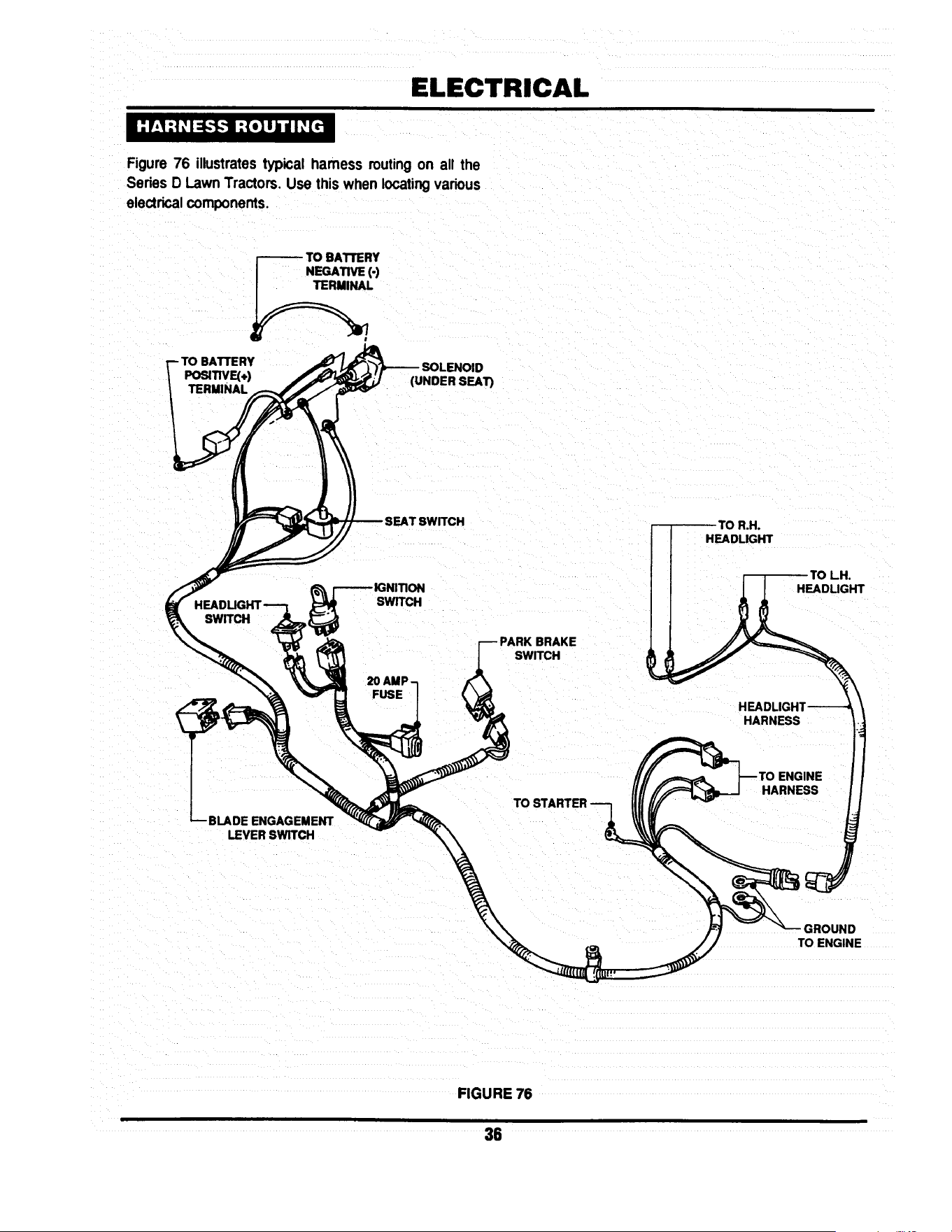
ELECTRICAL
Figure 76 illustratestypical hamess mutingon all the
Series D Lawn Tractors. Use this when locatingvarious
electricalcomponents.
_---- O BATI1ERY
NEGATIVE (-)
-TO BATTERY
PosmvF.(+)
TERMINAL
D
(UNDER SEAT)
R,H°
HEADLIGHT
SWITCH
BLADE ENGAGEMENT
LEVER SWITCH
SWITCH
20 AMP-
FUSE
BRAKE
SWITCH
HEADUGHT
HEAD
HARNESS
HARNESS
GROUND
TO ENGINE
FIGURE 76
36

ELECTRICAL
The schematics below, Figure 77 & Figure 78 represent
models with and without headlights.
BRIGGS & STRA TTON WITHOUT LIGHTS
STARTER k
"EDI
/-IGNITION
ENGINE /GROUND
RED
RED
'_--ALTERNATOR
BLACK RED
BATTERY
PEDAL SWITCH
INoj. I
I
I
BLACK
GREENI I N_ I II
I I BLACK
RED
I
B_ YELLOW
BLUE
FIGURE 77
BRIGGS & STRA TTON WITH LIGHTS
ANTI-AFTER FIRE
SOLENOID --_
\
\
ENGINE
STARTER
BLACK
BAI"rlERY
IGNmON GROUND
AC OUTPUT
RED
PINK
RED
ALTERNATOR
RED
SOLENOID
RED
PEDAL
SWITCH
BLACK
PTO
SWITCH
RED
BLACK
BLACK
UGHT
SWITCH
_mTION
KEYswrrc_
YEllOW
SEAT
SWITCH
IN_ I
I" Tl
r
HEAD
UGHTS
SEAT
SWITCH
GREEN
PURPLE
FIGURE 78
37

!
3 YEAR LIMITED WARRANTY
For three (3) years from purchase date for the original purchaser's residential, non-commercial use, SNAPPER, through
any SNAPPER dealer will replace, free of charge (except for taxes where applicable), any part.or parts found upon
examination by the factory at McDonough, Georgia, to be defective in material or workmanship or both.
For ninety (90) days from purchase date for the odginal purchaser's commercial, rental, or other non-residential use
SNAPPER, through any SNAPPER dealer will replace, free of charge, any part or parts found upon examination by th=
factory at McDonough, Georgia, to be defective in material or workmanship or both.
All transportation costs incurred by the purchaser in submitting material to a SNAPPER dealer for replacement under
this warranty must be paid by the purchaser.
This warranty does not apply to engines and their components, hydro transmissions, gear drive transmissions and
batteries, as these items are warranted separately. This warranty does not apply to parts that have been damaged by
accident, alteration, abuse, improper lubrication, normal wear, or other cause beyond the control of SNAPPER. This
warranty does not cover any machine or component part that has been altered or modified changing safety,
performance, or durability.
There is no other express warranty.
DISCLAIMER OF WARRANTY
Implied warranties, including those of merchantability and fitness for a particular purpose, are limited to three
(3) years from purchase date for the original purchaser's residential or other non-commercial use, and ninety
(90) days from purchase for the original purchaser's commercial, rental or other non-residential use, and to the
extent permitted by law, any and all implied warranties are excluded. This is the exclusive remedy. Liabilities
for consequential damages, under any and all warranties are excluded.
Some states do not allow limitations on how long an implied warranty lasts, or do not allow the exclusion or
limitation of incidental or consequential damages, so the above limitation or exclusion may not apply to you.
This warranty gives you specific legal rights, and you may also have other rights which vary from state to state.
WARNING: THE USE OF REPLACEMENT PARTS OTHER THAN GENUINE SNAPPER PARTS MAY IMPAIR THE
SAFETY OF SNAPPER PRODUCTS AND WILL VOID ANY LIABILITY AND WARRANTY BY SNAPPER
ASSOCIATED WITH THE USE OF SUCH PARTS.
IMPORTANT: Please fill outthe attachedSNAPPER Product RegistrationCard immediatelyand mail to:
Snapper's Product Registration Center, P.O. Box 777, McDonough, Georgia 30253

SERVICE NOTES

SERVICE NOTES

Safety Instructions & Operator's Manual for
8NAPPER
LAWN TRA C TOR
HYDROSTA TIC &
GEAR DRIVE
SERIES D
IA WARNING: The engine exhaust from this product contains chemicals known to the State I
of Califomia to cause cancer, birth defects or other reproductive harm.
I
COPYRIGHT © 1998
SNAPPER INC
ALL RIGHTS RESERVED
MANUAL No. 3-5576 (REV. 2, 6/98)

