Loading ...
Loading ...
Loading ...
Anti-Tip Bracket (cent&)
Step 2
Anti-tip bracket installation
A. Wood Construction:
Floor: Drill a 1/8"pilot hole in
the center of each pre-marked
wood floor hole position (a nail
or awl may be used if a drill is
not available),
AND
=
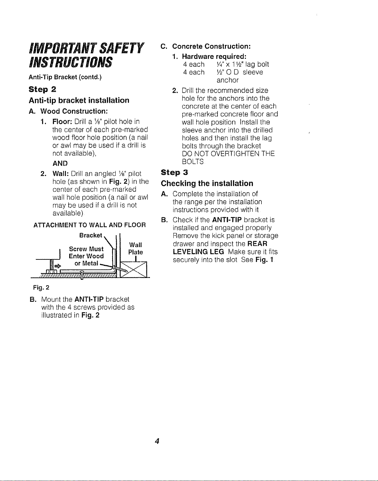
Wall: Drill an angled t/8"pilot
hole (as shown in Fig. 2)in the
center of each pre-marked
wall hole position (a nail or awl
may be used if a drill is not
available)
ATTACHMENT TO WALL AND FLOOR
Bracket _
i Screw Musty
Enter Wood|
_j_L=F or Metal
Fig. 2
B.
Wall
Plate
Mount the ANTI-TIP bracket
with the 4 screws provided as
illustrated in Fig, 2
C. Concrete Construction:
=
Hardware required:
4 each I/4"x 1t/2"lag bolt
4 each W'O D sleeve
anchor
w Drill the recommended size
hole for the anchors into the
concrete at the center of each
pre-marked concrete floor and
wall hole position Install the
sleeve anchor into the drilled
holes and then install the lag
bolts through the bracket
DO NOT OVERTtGHTEN THE
BOLTS
Step 3
Checking the installation
A. Complete the installation of
the range per the installation
instructions provided with it
B. Check if the ANTI-TIP bracket is
installed and engaged properly
Remove the kick panel or storage
drawer and inspect the REAR
LEVELING LEG Make sure it fits
securely into the slot See Fig. 1
4
Loading ...
Loading ...
Loading ...