Volt Check
™
Voltage and Continuity Tester
• Read this owners manual thoroughly before use and save.
PRESSPRESS
SPERRY
INSTRUMENTS
VC61000
SPERRY
INSTRUMENTS
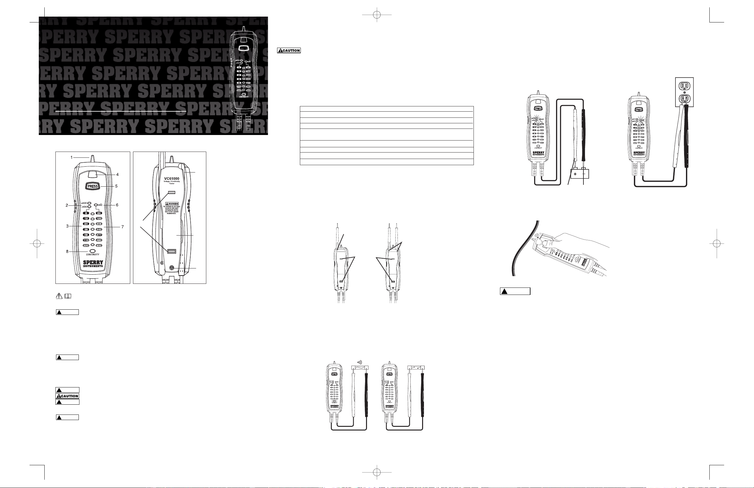
1.0 METER FUNCTIONS
2.0 Read First: Important Safety Information
Read this operators manual thoroughly before using
this tester. This manual is intended to provide basic information regarding this tester and to describe
common test procedures which can be made with this unit. Many types of appliance, machinery and other electrical
circuit measurements are not addressed in this manual and should be handled by experienced service technicians.
Use extreme caution when using this tester. Improper use of this tester can result in severe damage
to property, severe personal injury or death. Follow all instructions and suggestions in this
operators manual as well as observing normal electrical safety precautions. Do not use this tester if you are
unfamiliar with electrical circuits and proper test procedures.
SAFETY WARNINGS
This instrument has been designed, manufactured and tested according to IEC61010: Safety requirements for Electronic
Measuring apparatus, and delivered in the best condition after passing inspection.This instruction manual contains
warnings and safety rules which must be observed by the user to ensure safe operation of the instrument and retain it in
safe condition.Therefore, read through these operating instructions before using the instrument.
• Read through and understand the instructions contained in this manual before using the instrument.
Keep the manual at hand to enable quick reference whenever necessary.
• The instrument is to be used only in its intended applications.
• Understand and follow all the safety instructions contained in the manual.
• It is essential that the above instructions are adhered to.
• Failure to follow the above instructions may cause injury, instrument
damage and/or damage to equipment under test.
is reserved for conditions and actions that can cause serious or fatal injury.
is reserved for conditions and actions that can cause injury or instrument damage.
Never make measurement on a circuit in which voltage over AC 600 V exists.
• Do not attempt to make measurement in the presence of flammable gasses. Otherwise, the use of the instrument may
cause sparking, which can lead to an explosion.
Never attempt to use the instrument if its surface or your hand is wet.
• Do not exceed the maximum allowable input of any measuring range.
• Never open the battery cover during a measurement.
• The instrument is to be used only in its intended applications or conditions. Otherwise, safety functions equipped with
the instrument don’t work, and instrument damage or serious personal injury
may be caused.
• Never attempt to make measurement if any abnormal conditions, such as broken case and exposed metal parts are
found on the instrument.
• Do not install substitute parts or make any modification to the instrument. For repair or re-calibration, return the
instrument to your local distributor from where it was purchased.
• Verify proper operation on a known source before use or taking action as a result of the indication of the instrument.
Use appropriate personal protective equipment such as insulating gloves, insulating boots, and safety glasses.
• Set the function switch to an appropriate position before starting measurement.
• Do not expose the instrument to the direct sun, high temperature and humidity or dewfall.
• Altitude 2000m or less. Appropriate operating temperature is within 0 °C and 32 °C.
• This instrument isn’t dust and water proofed. Keep away from dust and water.
• When the instrument will not be in use for a long period, place it in storage after removing the battery.
• Cleaning: Use a cloth dipped in water or neutral detergent for cleaning the instrument. Do not use abrasives or solvents
otherwise instrument may get damaged, deformed or discolored.
4.0 OPERATING SUGGESTIONS
1) Avoid placing the meter in areas where vibration, dust or dirt are present. Do not store the meter in excessively hot,
humid or damp places.This meter is a sensitive measuring device and should be treated with the same regard as other
electrical and electronic devices.This tool is designed to check for voltage levels and to determine continuity. No other test
functions can be performed.
2) Using the meter in areas with high magnetic fields can result in inaccurate readings.
3) Never immerse the meter in water or solvents.To clean the housing use a damp cloth with a minimal amount of mild
soap.
4) This meter is designed with probe holders and magnets to allow for maximum versatility and single hand testing.
Refer to the drawings in Fig. 1 for common setups.
4.1 Automatic Operation
When using the test leads, the tester will automatically activate when connected to AC or DC voltage, or when continuity
is made.The tester will automatically select the proper function.
4.2 Testing Continuity
Touch the tip of the test leads to the points where tests need to be made. If the resistance is below 50 ohms, the beeper
will sound and the continuity light will illuminate. Fig. 2
4.3 Measuring DC Voltage Levels
Measure the voltage by touching the test lead tips to the circuit where the value of voltage is expected. If the red test lead
is on the positive contact the +VDC light will illuminate.If the red test lead is on the negative contact the -VDC light will
illuminate. Fig. 3
Read the voltage level from the DC voltage scale.
4.4 Measuring AC Voltage Levels
Measure the voltage by touching the test lead tips to the circuit where the value of voltage is needed.The VA
~
C light will
illuminate to indicate AC Voltage. Fig. 4
Read the level from the AC voltage scale. The polarity of the leads does
not matter for AC voltage measurements.
4.5 Non-contact AC Voltage Detector
Depress the non-contact AC voltage button.The speaker will chirp once if the batteries are good. If the speaker does not
chirp, replace the batteries and retest before use.Fig. 5
Do not place hand past button.
To use, press button and place sensing tip on or near wire or device. If AC voltage greater than 50 V
AC is present, light will glow and speaker will continuously chirp
5.0 CHANGING THE BATTERIES
Do not open tester case while using the tester.
1) When the battery voltage drops below proper operating range, the tester will no longer function.
2) Open the back cover by removing the screw. Slide the cover down and replace old batteries with three new
AAA size batteries.
3) Close the back cover and fasten the screw.
(Refer to 1.0, Meter Functions)
!
WARNING
12
10
9
11
!
DANGER
DANGER
!
WARNING
WARNING
!
WARNING
WARNING
!
DANGER
DANGER
!
WARNING
WARNING
Fig. 2
1. Non-contact AC sensor
2. DC Polarity Indicators
3. DC Voltage Scale
4. Non-contact AC
Indicator
5. Non-contact AC Button
6. AC Voltage Indicator
7. AC Voltage Scale
8. Continuity Indicator
9. Battery Compartment
Screw
10. Battery Compartment
11. Magnets
12. Test Probe Storage
Area
Beeper / light
No Reaction
Red
Black
Fig. 4
2.0 SPECIFICATIONS
DC Voltage: 6 – 220 Volts
Contact AC Voltage: 24 – 600 Volts
Non-Contact AC Voltage: 50 – 600 Volts
AC voltage Fequency 50 – 60 Hz
Operating Environment :
5 °C to 40 °C(5 to 104 °F); Max RH 80% to 31 °C
(88 °F) decreasing linearly to 50% RH at 40 °C (104 °F).
Storage Temperature: 14 °F – 140 °F (-10 °C – 60 °C)
Accuracy: LED's illuminate at -16% of displayed value
Batteries: (3) three AAA
CAT IV 600 V / CAT III 1000 V
Fig. 1
Single Hand Probes slide
in housing
Magnetic
back
Fig. 3
Fig. 5
2150 Joshua’s Path, Suite 302, Hauppauge, NY 11788
1*800-645-5398
www.sperryinstruments.com
SPERRY
INSTRUMENTS
The Professional’s Choice®
©SPERRY INSTRUMENTS, INC.
VC61000 SingleSheet 10/23/06 4:46 PM Page 1