
BCT & BLCT
COMBI OVENS
INSTALLATION - OPERATION - MAINTENANCE
BLODGETT OVEN COMPANY
www.blodgett.com
44 Lakeside Avenue, Burlington, Vermont 05401 USA Telephone: (802) 658-6600 Fax: (802)864-0183
PN 61041 Rev J (11/15)
© 2015 - G.S. Blodgett Corporation

Your Service Agency’s Address:
Model
Serial number
Oven installed by
Installation checked by

TABLE OF CONTENTS
INSTALLATION
Utility Connections - Standards and Codes ................................. 2
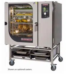
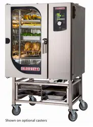
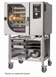
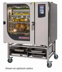
The Blodgett Combi-Oven/Steamer ........................................ 3
Description of the Combi-Oven/Steamer ................................... 4
Utility Specications ...................................................... 5
Oven Assembly to Stand .................................................. 6
Oven Location and Leveling ............................................... 7
Plumbing Connections .................................................... 8
Electrical Connection and Ventilation ...................................... 10
Gas Connection......................................................... 11
Gas Hose Restraint ..................................................... 13
Final Check Lists ........................................................ 14
OPERATION
Safety Information for Gas Ovens ........................................ 15
BCT Touchscreen Control Description ..................................... 16
Main Menu ............................................................. 17
Hot Air Mode ........................................................... 18
Steam Mode ............................................................ 20
Retherm Mode .......................................................... 21
CombiSmart Mode ...................................................... 22
CombiOptima Mode ..................................................... 23
Using the Core Probe ................................................... 24
SmartChef Automatic Cooking ........................................... 26
Using Rack Timing ...................................................... 28
Using Advanced Rack Timing ............................................ 29
PreHeat, Cool Down and Proong ........................................ 32
Cook to Perfection ...................................................... 34
Programmed Cooking ................................................... 35
Adding a New Recipe Program ........................................... 36
Favorites ............................................................... 37
USB ................................................................... 38
Timed Start ............................................................. 40
HACCP Library ......................................................... 41
MAINTENANCE
Cleaning & Preventative Maintenance..................................... 42
Deliming - BCT only ..................................................... 44
IMPORTANT
WARNING: Improper installa-
tion, adjustment, alternation,
service or maintenance can
cause property damage, in-
jury or death. Read the instl-
lation, operation and mainte-
nance instructions thoroughly
before installing or servicing
this equipment.
INSTRUCTIONS TO BE FOL-
LOWED IN THE EVENT THE
USER SMELLS GAS MUST BE
POSTED IN A PROMINENT LO-
CATION. This information may
be obtained by contacting your
local gas supplier.
FOR YOUR SAFETY
Do not store or use gasoline or
other ammable vapors or liq-
uids in the vicinity of this or any
other appliance.
The information contained in this
manual is important for the prop-
er installation, use, and mainte-
nance of this oven. Adherence
to these procedures and instruc-
tions will result in satisfactory
baking results and long, trou-
ble free service. Please read
this manual carefully and retain
it for future reference.
ERRORS: Descriptive, typo-
graphic or pictorial errors are
subject to correction. Speci-
cations are subject to change
without notice.

2
Installation
Utility Connections - Standards and Codes
THE INSTALLATION INSTRUCTIONS CONTAINED
HEREIN ARE FOR THE USE OF QUALIFIED INSTAL-
LATION AND SERVICE PERSONNEL ONLY. INSTAL-
LATION OR SERVICE BY OTHER THAN QUALIFIED
PERSONNEL MAY RESULT IN DAMAGE TO THE OVEN
AND/OR INJURY TO THE OPERATOR.
Qualied installation personnel are individuals, a rm,
a corporation, or a company which either in person or
through a representative are engaged in, and responsible
for:
• the installation or replacement of gas piping and the
connection, installation, repair or servicing of equip-
ment.
• the installation of electrical wiring from the electric
meter, main control box or service outlet to the elec-
tric appliance.
Qualied installation personnel must be experienced in
such work, familiar with all precautions required, and have
complied with all requirements of state or local authorities
having jurisdiction.
U.S. and Canadian installations
The installation must conform with local codes, or in the
absence of local codes, with the National Fuel Gas Code,
ANSI Z223.1/NFPA 54, or the Natural Gas and Propane
Installation Code, CSA B149.1, as applicable.
Installation must conform with local codes, or in the ab-
sence of local codes, with the National Electrical Code,
ANSI/NFPA 70-Latest Edition and/or Canadian National
Electric Code C22.1 as applicable.
Appliance is to be installed with backow prevention in
accordance with applicable federal, province and local
codes.
Australia and general export installations
Instllation must conform with Local and National instal-
lation standards. Local installation codes and/or require-
ments may vary. If you have any questions regarding the
proper installation and/or operation of your Blodgett oven,
please contact your local distributor. If you do not have a
local distributor, please call the Blodgett Oven Company
at 0011-802-658-6600.

3
Installation
The Blodgett Combi-Oven/Steamer
The Blodgett Combi-Oven/Steamer offers a completely
new method of cooking. With the Oven/Steamer you have
the choice of two cooking processes: Steam and Hot Air,
either...
• Separately
• Combined, or
• In Sequence
And for easy operation you can choose from three modes:
In the Steam mode you can:
steam reheat reconstitute
stew thaw simmer
blanche preserve braise
poach
In the Hot Air mode you can:
roast bake grill
gratinate broil
In the Combination Steam and Hot Air mode you can:
defrost roast rethermalize
reheat bake forced steam
There are four additional specialized modes to help you
make the most of your time:
Retherm - for perfect reheating
Proong - Proof and bake all in the same oven
Preheat - in this mode the oven will preheat to 575ºF
(300ºC) for 15 minutes. The oven will then automatically
lower to 480ºF (249ºC) to protect the advanced elec-
tronic components.
Cool Down - allows the oven cavity to cool down rapidly
with the door opened
You can also use two or three functions in se-
quence during one cooking process. We call this:
• combi-steaming
• combi-roasting
• combi-baking
The combination of circulating hot air and steam in the
space saving, high performance Combi-Oven/Steamer
leads to improvements in the following areas:
• increased productivity in the kitchen
• a reduction in capital expenditures for multiple equip-
ment replacement
• a wider range of menu choices
• a simplied cleaning process
The work process is simplied since products are pre-
pared on or in steam table pans and trays. Food can be
cooked, stored, and transported with the same pans.
Small amounts of product can be processed efciently;
pre-cooked and convenience foods can be reheated with-
in minutes. Many frozen foods can be processed with-
out pre-thawing. This exibility in preparation reduces the
need for kettles and steam tables since there is no need
for large amounts of food to be kept warm for long periods
of time.
Today the improvement of food quality is more important
than ever. Vegetables are cooked in the Blodgett Combi-
Oven/Steamer without water at the optimal temperature
of just under 212ºF (100ºC), maintaining valuable vita-
mins, minerals, nutrients and trace elements. Cooking
meat in the Combi results in less shrinkage and a rmer,
juicier product. The Blodgett Combi-Oven/Steamer is be-
ing used more and more for baking. Steam and Hot Air
modes make it a general purpose baking appliance.

4
Installation
Description of the Combi-Oven/Steamer
ABOUT THE OVEN/STEAMER
Blodgett Combis are quality produced using high-grade
stainless steel with rst class workmanship.
The multiple speed fan, which is guarded against acci-
dental nger contact, is driven by a quiet and powerful
motor. The condenser draws out excess steam from the
appliance. Condensation and waste water, which result
during steaming and cleaning, are continuously drained.
The use of high quality insulation impedes excessive heat
radiation and saves energy.
Fresh steam enters the oven cavity without pressure and
circulates at high speed. This process enables quick and
gentle cooking and ensures high quality food while pro-
viding convenient working methods. The steam generator
is completely automatic and protected from running dry.
OVEN/STEAMER OPERATION
The practical oven door, with a viewing window, has a
wide swing radius and handle which can be operated eas-
ily, even with wet or greasy hands.
Ease of operation is guaranteed through the simple to use
control. With graphical symbols and storage for 50 prod-
uct recipes the BCT/BLCT is easy for even inexperienced
kitchen staff to operate.
Cleaning is kept to a minimum thanks to the automatic
Combi Wash system.
PLUMBING SPECIFICATIONS
WATER
Water pressure 36.26 PSI (250 kPa, 2.5 bar) during Combi Wash
21.76 PSI (150 kPa, 1.5 bar) when Combi Wash is not active
40(min)-50(max) PSI supply pressure
Water connection 3/4” garden hose cold water
Water quality requirements TDS: 40-125 ppm
Hardness: 35-100 ppm
Chlorides: <25 ppm
Silica: <13 ppm
Chlorine: < 0.2 ppm
Chloramine: < 0.2 ppm
pH: 7.0-8.5
DRAINAGE
Drain type Atmospheric Vented Drain
Drain connection 2.00” (50.8mm) Copper
1.57” (40mm) Copper - mini combi ovens
Maximum water drain temperature 140ºF (60ºC)
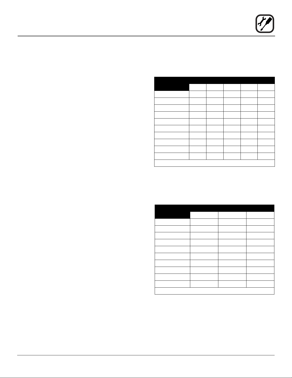
RATINGS - GAS OVENS
Model Gas Type Input Voltage Phase Amps
BLCT-61G Natural 58,000 BTU 115 1 9
Propane 58,000 BTU 115 1 9
BLCT-101G Natural 87,000 BTU 115 1 9
Propane 87,000 BTU 115 1 9
BLCT-102G Natural 95,500 BTU 115 1 9
Propane 95,500 BTU 115 1 9
BLCT-62G Natural 81,800 BTU 115 1 9
Propane 81,800 BTU 115 1 9
BLCT-202G Natural 190,000 BTU 115 1 17
Propane 190,000 BTU 115 1 17

5
Installation
Utility Specications
ELECTRICAL RATINGS
Model Voltage kW Hz Phase Max Load (amps)
BLCT-23E
Mini Combi
208/230/240
2.7/3.3/3.6 50/60 1NAC 15
2.7/3.3/3.6 50/60 2AC 15
5.4/6.6/7.2 50/60 3AC 30
400/415
6.6/7.2 50/60 2NAC 15
5.4/5.8 50/60 2AC 15
440/480 5.4/6.5 50/60 2AC 15
BLCT-6E
Mini Combi
208 4.6 50/60 1 23
240 6.1 50/60 1 26
208 6.9 50/60 3 20
240 9.2 50/60 3 23
BLCT-10E
Mini Combi
208/230/240
10.4/12.7/13.8 50/60 3AC 34
10.4/12.7/13.8 50/60 3NAC 34
400/415
12.7/13.8 50/60 3NAC 20
12.7/13.8 50/60 3AC 20
440/480 10.4/12.4 50/60 3AC 18
BCT-61E
BLCT-61E
208 9 60 3 25
240 9 60 3 22
480 9 60 3 11
BCT-101E
BLCT-101E
208 18 60 3 50
240 18 60 3 44
480 18 60 3 22
BCT-102E
BLCT-102E
208 27 60 3 75
240 27 60 3 65
480 27 60 3 33
BCT-62E
BLCT-62E
208 21 60 3 59
240 21 60 3 51
480 21 60 3 26
BCT-202E
BLCT-202E
208 60 60 3 167
240 60 60 3 145
480 60 60 3 73

6
Installation
Oven Assembly to Stand
Your Blodgett COMBI oven has been shipped with black
plastic caps on the corners of its base. In order to mount
your oven to its stand, please do the following:
1. Remove the stand from the packaging. Install the
casters or feet into the base of the stand. If inserting
casters ensure that the locking casters are at the front
of the stand, see gure. Place the stand upright in an
area readily available.
2. Remove all packaging from the oven, so that the oven
can be picked up.
3. Remove the black plastic caps on each corner by
removing the two screws holding them on. Do NOT
discard these screws; they will be used to mount the
oven to the stand.
4. Position the oven over the stand and align the corner
brackets on the stand with the holes on the oven.
5. Use the screws from the plastics caps to mount the
oven to the stand.
6. The oven has now been properly fastened to the
stand.
Note difference in rail
placement
Front of stand
Figure 1
7
Installation
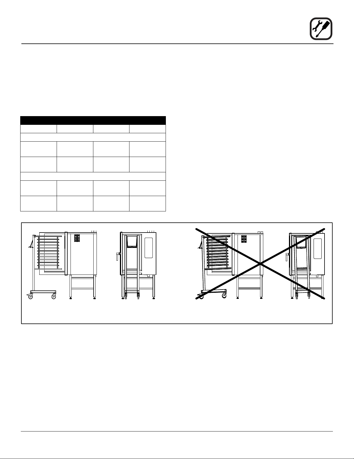
Oven Location and Leveling
The well planned and proper placement of your oven will
result in long term operator convenience and satisfactory
performance.
Certain minimum clearances must be maintained be-
tween the oven and any combustible or non-combustible
construction.
MINIMUM REQUIRED CLEARANCES
Size Left Right Back
Electric Ovens
61, 101,
102 & 202
2.75”
(70mm)
2.75”
(70mm)
2”
(50mm)
62 0”
(0mm)
4”
(102mm)
2”
(50mm)
Gas Ovens
61, 101,
102 & 202
2.75”
(70mm)
2.75”
(70mm)
2”
(50mm)
62 0”
(0mm)
4”
(102mm)
2”
(50mm)
Strong sources of heat such as hotplates, tilting frying
pans, deep fat fryers, etc. should not be placed near the
oven, especially near its right side. An optional side heat
shield is available.
In addition, the following clearances are recommended
for servicing.
• Oven body sides - 12” (30cm)
• Oven body back - 12” (30cm)
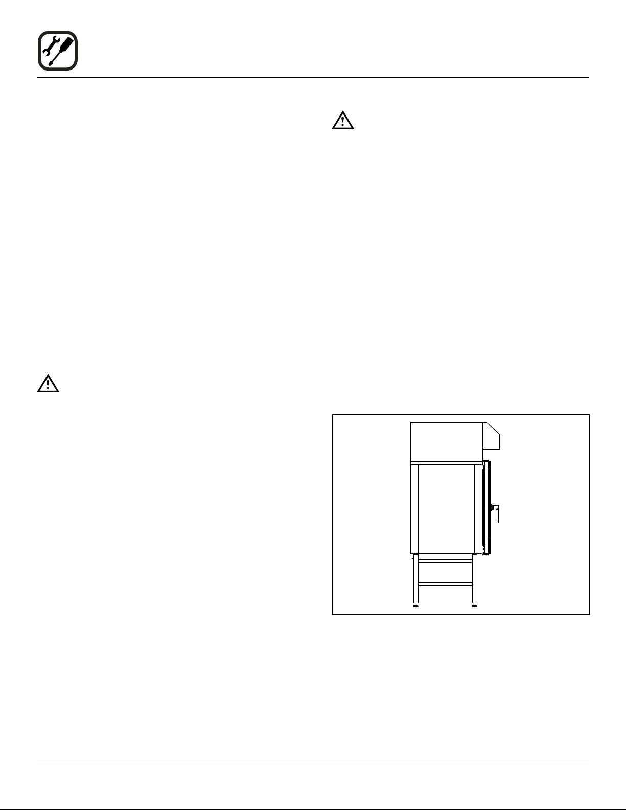
To ensure that the oven functions correctly when installed,
it should be placed upright and level (horizontally). This is
measured at the front and side edge of the roof. The oven
can be levelled using the adjusting screws on the stand or
on the legs of table models. The height of the oven should
also be adjusted to t the trolley for rack.
Correct Installation Incorrect Installation
Figure 2

8
Installation
Plumbing Connections
WATER CONNECTION
Blodgett BCT/BLCT ovens have two water connections.
Both are located at the back of the unit.
BCT/BLCT-61, 62, 101, 102 and 202 models
• 1 connection for raw water for the condensation jet.
• 1 connection for steam generation and the Combi
Wash jet in the oven chamber. Must meet the re-
quirements applying to water supplied to household
appliances.
Quench
Steam
Figure 3
BLCT-23, 6 and 10 Mini Combi models
• 1 water connection. Must meet the requirements ap-
plying to water supplied to household appliances.
Water
connection
Figure 4
WARNING!!
If the water temperature exceeds 70°F (21°C),
problems with regard to Combi Optima cali-
bration and cooling of the oven may occur.
The water connection must be carried out by
an authorized plumber in accordance with
existing local codes.
Clogged up water lters and dirt in the sole-
noid valves are not covered by the warranty.
To facilitate cleaning and servicing, the oven should be
connected with an approved exible 3/4” hose. Perma-
nent installations should be tted with a stop-tap and a
non-return valve.
Before connecting the oven to water, ush the tubes
thoroughly. Connect the oven.
DRAIN CONNECTION
Blodgett ovens are equipped with a drain system that re-
moves surplus water from the oven chamber. This may
be condensed water from the products, or it may occur
when the oven chamber is cooled down with cold water,
or when the oven chamber is cleaned.
WARNING!!
Connection must be carried out by an autho-
rised plumber, to an open or closed drain.
The drain must never end directly beneath the
oven.
The drain must be of stainless steel or an equally
temperature-resistant material, have a fall of at least 3°
or 5%. See page 4 for drain diameter.

9
Installation
Plumbing Connections
CLEANING & DELIMING CHEMICAL
1. BCT/BLCT-61, 62, 101, 102 and 202 ovens only. The
oven is supplied with a chemical bottle holder. The
holder can be afxed to either side of the oven. Place
it on the stand crossmember.
Figure 5
2. Connect the supplied detergent tubes (red and blue)
to the underside of the oven near the rear. Connect
the blue hose to the tting with the blue sticker and
the red hose to the tting with the red sticker.
Red Sticker
Blue Sticker
Red Tube
Blue Tube
Figure 6
3. Insert the blue and red hoses into the proper bottles.
Red is for detergent, blue is for rinse aid.
4. BCT only - The last line is for the delimer. This is the
tan colored tube protroding from the bottom of the
oven. Cut the tubing to the proper length, if needed,
and place the tubing into the delime bottle.
NOTE: If the tube is cut to length, remove the stain-
less steel weight from the end of the tube
and reinsert.
10
Installation
Electrical Connection and Ventilation
ELECTRICAL CONNECTION
NOTE: Electrical connections must be performed by a
qualied installer only.
Before making any electrical connections to these appli-
ances, check that the power supply is adequate for the
voltage, amperage, and phase requirements stated on
the rating name plate mounted on the appliance.
1. The rating plate is located on the right side of the
oven.
An approved plug outlet or a safety cutout must be locat-
ed close to the oven so that the oven can be disconnected
during installation and repair. The safety cutout must be
able to cut off all poles with a total distance of break of at
least 3 mm.
All appliances must be installed in accordance with Local
or National Electrical codes.
The wiring diagram is located in the motor compartment.
NOTE: Disconnect the power supply to the appliance
before servicing.
WARNING!!
Improper installation may invalidate your war-
ranty.
Electric Models
A strain relief for the power supply cord is provided. The
installer must supply a cord that meets all Local and Na-
tional installation standards.
Gas Models
U.S. and Canadian Installations
A power cord (115V units only) is supplied with a plug at-
tached. Plug the power cord into the desired receptacle.
NOTE: The BLCT-202G must be hard wired.
This oven model uses a variable frequency inverter drive.
Appliances that use variable frequency inverter drives
produce high frequency noise and require lters and
shielded motor cabling. This causes higher leakage cur-
rent toward Earth Ground. Especially, at the moment of
switching ON this can cause an inadvertent trip of the ap-
pliance’s ground fault interrupter (GFCI). Some GFCIs
are more sensitive than others. Blodgett has qualied the
Pass and Seymour brand, part number 2095, 20 A, 125
VAC, 60 Hz, specication grade GFCI duplex receptacle
as being immune to the variable frequency inverter drive’s
noise. Blodgett recommends using this specic GFCI for
this model oven.
WARNING!!
If the supply cord is damaged, it must be re-
placed by a special cord or assembly available
from the manufacturer or its service agent.
VENTILATION
Blodgett BCT/BLCT ovens are equipped with an open/di-
rect exhaust system that removes surplus humidity from
the oven chamber. The exhaust system has an electrically
operated damper.
The ventilation motor can be controlled directly from the
oven. This means that the ventilation starts when a pro-
gram is started and runs for 10 minutes after the program
is completed.
BCT/BLCT-61, 62, 101, 102 and 202 ovens only. The ex-
haust tube can be connected to a ventilation system. In
that case, a special extraction funnel is tted to avoid suc-
tion directly from the oven chamber. This extraction funnel
can be ordered from Blodgett.
If an extraction hood is installed in the ceiling above the
oven, it should project 20” (50 cm) over the front of the
oven.
Figure 7
11
Installation
Gas Connection
GAS PIPING
A properly sized gas supply system is essential for maxi-
mum oven performance. Piping should be sized to pro-
vide a supply of gas sufcient to meet the maximum de-
mand of all appliances on the line without loss of pressure
at the equipment.
Example:
NOTE: BTU values in the following example are for
natural gas.
You purchase a BLCT-61G to add to your existing cook
line.
1. Add the BTU rating of your current appliances.
Pitco Fryer 120,000 BTU
6 Burner Range 60,000 BTU
Deck Oven 50,000 BTU
Total 230,000 BTU
2. Add the BTU rating of the new oven to the total.
Previous Total 230,000 BTU
BLCT-61G 40,900 BTU
New Total 270,900 BTU
3. Measure the distance from the gas meter to the cook
line. This is the pipe length. Let’s say the pipe length
is 40’ (12.2 m) and the pipe size is 1” (2.54 cm).
4. Use the appropriate table to determine the total ca-
pacity of your current gas piping.
The total capacity for this example is 375,00 BTU. Since
the total required gas pressure, 270,900 BTU is less than
375,000 BTU, the current gas piping will not have to be
increased.
NOTE: The BTU capacities given in the tables are for
straight pipe lengths only. Any elbows or other
ttings will decrease pipe capacities. Contact
your local gas supplier if you have any ques-
tions.
Maximum Capacity of Iron Pipe in Cubic Feet of
Natural Gas Per Hour
(Pressure drop of 0.5 Inch W.C.)
PIPE
LENGTH (FT)
NOMINAL SIZE, INCHES
3/4” 1” 1-1/4” 1-1/2” 2”
10 360 680 1400 2100 3950
20 250 465 950 1460 2750
30 200 375 770 1180 2200
40 170 320 660 990 1900
50 151 285 580 900 1680
60 138 260 530 810 1520
70 125 240 490 750 1400
80 118 220 460 690 1300
90 110 205 430 650 1220
100 103 195 400 620 1150
From the National Fuel Gas Code Part 10 Table 10-2
Maximum Capacity of Pipe in Thousands of
BTU/hr of Undiluted L.P. Gas at 11” W.C.
(Pressure drop of 0.5 Inch W.C.)
PIPE
LENGTH (FT)
OUTSIDE DIAMETER, INCHES
3/4” 1” 1-1/2”
10 608 1146 3525
20 418 788 2423
30 336 632 1946
40 287 541 1665
50 255 480 1476
60 231 435 1337
70 215 404 1241
80 198 372 1144
90 187 351 1079
100 175 330 1014
From the National Fuel Gas Code Part 10 Table 10-15
12
Installation
Gas Connection
PRESSURE REGULATION AND TESTING
The gas pressure to the appliance must be rated for each
appliance while the burners are on. A sufcient gas pres-
sure must be present at the inlet to satisfy these condi-
tions. Refer to the table below for correct gas pressure.
Each appliance has been adjusted at the factory to oper-
ate with the type of gas specied on the rating plate.
Each oven is supplied with a regulator to maintain the
proper gas pressure. The regulator is essential to the
proper operation of the oven and should not be re-
moved.
DO NOT INSTALL AN ADDITIONAL REGULATOR
WHERE THE UNIT CONNECTS TO THE GAS SUPPLY
UNLESS THE INLET PRESSURE IS GREATER THAN
14” W.C. (1/2 PSI) (37mbar).
The oven and its individual shutoff valve must be discon-
nected from the gas supply piping system during any
pressure testing of that system at test pressures in ex-
cess of 1/2 psig (3.45kPa).
The oven must be isolated from the gas supply piping
system by closing its individual manual shutoff valve dur-
ing any pressure testing of the gas piping system at test
pressures equal or less than 1/2 psig (3.45kPa).
Prior to connecting the appliance, gas lines should be
thoroughly purged of all metal lings, shavings, pipe
dope, and other debris. After connection, the appliance
must be checked for correct gas pressure.
U.S. and Canadian Installations
Installation must conform with local codes, or in the ab-
sence of local codes, with the National Fuel Gas Code,
NFPA54/ANSI Z223.1-Latest Edition, the Natural Gas In-
stallation Code CAN/CGA-B149.1 or the Propane Instal-
lation Code, CAN/CGA-B149.2 as applicable.
General Export Installations
Installation must conform with Local and National instal-
lation standards. Local installation codes and/or require-
ments may vary. If you have any questions regarding the
proper installation and/or operation of your appliance,
please contact your local distributor. If you do not have a
local distributor, please call Blodgett Combi at 0011-802-
658-6600.
GAS PRESSURE
Model Gas Type Inlet Pressure
BLCT-61G Natural 3.2-8.0” W.C.
Propane 5.2-14” W.C.
BLCT-101G Natural 3.2-8.0” W.C.
Propane 5.2-14” W.C.
BLCT-102G Natural 3.2-8.0” W.C.
Propane 5.2-14” W.C.
BLCT-62G Natural 3.2-8.0” W.C.
Propane 5.2-14” W.C.
BLCT-202G Natural 3.2-8.0” W.C.
Propane 5.2-14” W.C.

13
Installation
Gas Hose Restraint
If the appliance is mounted on casters, a commercial ex-
ible connector with a minimum of 3/4” (1.9 cm) inside di-
ameter must be used along with a quick connect device.
A restraint must be used to limit the movement of the ap-
pliance so that no strain is placed upon the exible con-
nector. The restraint should be fastened to the base frame
of the oven as close to the exible connector as possible.
It should be short enough to prevent any strain on the
connector. With the restraint fully stretched the connector
should be easy to install and quick connect.
The restraint (ie: heavy gauge cable) should be attached
without damaging the building. DO NOT use the gas pip-
ing or electrical conduit for the attachment of the perma-
nent end of the restraint! Use anchor bolts in concrete or
cement block. On wooden walls, drive hi test wood lag
screws into the studs of the wall.
WARNING!!
If the restraint is disconnected for any reason
it must be reconnected when the appliance is
returned to its original position.
U.S. and Canadian installations
The connector must comply with the Standard for Con-
nectors for Movable Gas Appliances, ANSI Z21.69 or
Connectors For Moveable Gas Appliances CAN/CGA-
6.16 and a quick disconnect device that complies with the
Standard for Quick-Disconnect Devices for Use With Gas
Fuel, ANSI Z21.41 or Quick Disconnect For Use With Gas
Fuel CAN 1-6.9. Adequate means must be provided to
limit the movement of the appliance without depending
on the connection and the quick disconnect device or its
associated piping.
A drip leg must be used at each appliance. Refer to
NFPA54/ANSI Z223.1 - Latest Edition (National Fuel Gas
Code) for proper drip leg installation.
General export installations
Installation must conform with Local and National instal-
lation standards. Local installation codes and/or require-
ments may vary. If you have any questions regarding the
proper installation and/or operation of your appliance,
please contact your local distributor. If you do not have a
local distributor, please call Blodgett Combi at 0011-802-
658-6600.
Attachment Plate
(secure with leg mount bolt)
Gas Hose
Quick Connect
Gas Supply Line
Restraint
IMPORTANT: Cable restraint should
be fastened as close as possible
to the exible connector and short
enough to prevent any strain on the
exible connector.
At maximum stretch of shortened
restraint, the exible connector
should be easy to install and quick
to connect.
Installation of Gas Hose and Restraint
(Single Section Shown)
Figure 8

14
Installation
Final Check Lists
WARNING!!
Final check list must be performed by a quali-
ed installer only.
OVEN EXTERIOR
1. Check that the oven has not been damaged in transit
(dents, scratches, etc.)
2. Check/adjust the height and check that the oven is
placed level (horizontally)
3. Check/adjust oven door
CONNECTIONS
1. Check for correct water connection
2. Turn on water supply
3. Check for leaks
4. Turn off water supply
5. Check and clean dirt lter
6. Turn on water supply again
7. Check hand shower
8. Check for correct electrical connection
9. Check for correct gas connection (if applicable)
10. Check connection to drip tray
11. Check for correct mounting of drip tray
12. Check for correct fall of hose from drip tray, and check
for leaks
13. Check for correct exhaust and drain connection
14. Clean the oven
15. Apply steel oil
OVEN INTERIOR
1. Check that lter housing is mounted correctly
2. Check interior light
3. Clean the oven
CONTROL
1. Check and adjust, if necessary, each of the preset
values
2. Heat up the oven at 480°F (249°C) for approximately
5 minutes.

15
Operation
Safety Information for Gas Ovens
The information contained in this section is provided for
the use of qualied operating personnel. Qualied operat-
ing personnel are those who have carefully read the in-
formation contained in this manual, are familiar with the
functions of the oven and/or have had previous experi-
ence with the operation of the equipment described. Ad-
herence to the procedures recommended herein will as-
sure the achievement of optimum performance and long,
trouble-free service.
Please take the time to read the following safety and op-
erating instructions. They are the key to the successful
operation of your Blodgett oven.
SAFETY TIPS
For your safety read before operating
What to do if you smell gas:
• DO NOT try to light any appliance.
• DO NOT touch any electrical switches.
• Use an exterior phone to call your gas supplier im-
mediately.
• If you cannot reach your gas supplier, call the re
department.
What to do in the event of a power failure:
• Turn all switches to off.
• DO NOT attempt to operate the oven until the power
is restored.
NOTE: In the event of a shut-down of any kind, allow a
ve (5) minute shut off period before attempting
to restart the oven.
General safety tips:
• DO NOT use tools to turn off the gas control. If the
gas cannot be turned off manually do not try to re-
pair it. Call a qualied service technician.
• If the oven needs to be moved for any reason, the
gas must be turned off and disconnected from the
unit before removing the restraint cable. Reconnect
the restraint after the oven has been returned to its
original location.
• DO NOT remove the control panel cover unless the
oven is unplugged.

16
Operation
BCT Touchscreen Control Description
The BCT/BLCT ovens include the versatile Blodgett
Combi Touchscreen control. The control features:
• Multiple cooking modes include Hot Air, Com-
biSmart, CombiOptima, Retherm, Steam, Proong,
Cool Down, and PreHeat.
• CombiOptima automatically measures and controls
the humidity level in the oven, helping to retain the
appearance and juiciness of the product. (not avail-
able on mini ovens)
• Easy to use touch panel display
• Stores up to 1000 recipe programs with multiple
cooking stages. Recipes can be grouped into
categories (beef, chicken, cookies, etc.) for easy re-
trieval. Includes a favorites category for the recipes
you use the most.
• External core temperature probe with 3 measuring
points.
• Low temperature roast & hold and Delta-T cooking
• Reversible 9 speed fan for optimum baking and
roasting results
• The Rack Timer function enables you to set timers
for each individual rack.
• Advanced Rack Timer allows you to create groups
of recipes with similar characteristics (cook tempera-
ture, humidity level, etc.) then manage multiple reci-
pes of the same group simultaneously on separate
oven racks.
• USB port for data, software and recipe transfer
• HACCP quality control enables you to control and
document production. Includes production time,
production duration, preparation temperature, and
core temperature.
• Programmable time delay start
• Automatic service diagnosis
BASIC OPERATIONS
• To select an item, touch the button on the screen
• To scroll through a list, drag your nger up or down.
The item centered on the “wheel” will be selected.
• To return to the previous display, push the left arrow
key ◄ in the upper left corner of the screen.
• To change the cook function while the oven is oper-
ating, push the down arrow key ▼ in the upper right
corner of the screen.
• To save the current settings and move on to the next
step, push the right arrow key ► in the upper right
corner of the screen.
17
Operation
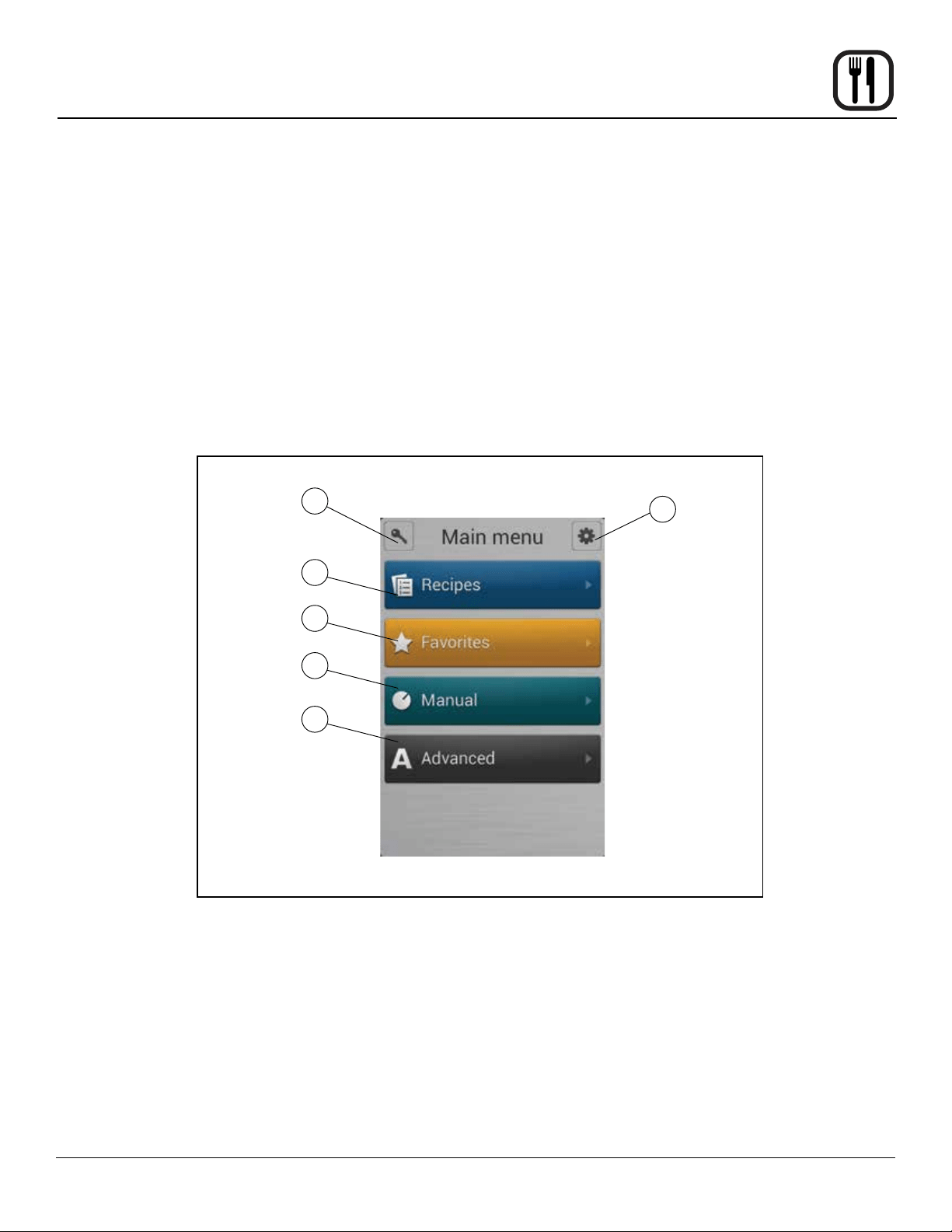
Main Menu
MAIN MENU DESCRIPTION
1. KEY ICON - Press this key, then enter the code to
change type of user. Choices include user, super user
or technician. The super user code is 87 64 12.
2. GEAR ICON - Press to access the service and super
user menus.
3. RECIPES - Press to cook using programmed recipes
or to create a new recipe.
4. FAVORITES - Press to access the favorites category.
This category can be used to store the recipes you
use the most. The favorites category can store both
factory programmed and your own recipes.
5. MANUAL - Press to cook manually using Steam, Hot
Air, CombiSmart, CombiOptima, or Retherm modes.
Also press to access CombiWash.
6. ADVANCED - Press to access Preheat, Cool Down,
Advanced Rack Timer and Proong modes. Also pro-
vides access to USB, HAACP and timed cook start.
Figure 9
1
3
4
5
6
2

18
Operation
Hot Air Mode
Entering the Hot Air Mode
1. From the MAIN MENU, press the MANUAL key.
2. Select the HOT AIR mode.
Setting the Cook Time and Temperature
1. In the TEMPERATURE list, drag your nger up or
down to select the desired cook temperature.
To switch to keypad entry - Swipe your nger from
right to left across the upper portion of TEMPERA-
TURE scroll dial. Select the keypad icon from the
center of the box to bring up the keypad. Enter the
desired temperature. Press OK at the bottom of the
screen to set the temperature.
NOTE: To return to the scroll wheel, swipe the up-
per portion of keypad icon box from left to
right. The control defaults to the last entry
method used.
2. In the HOUR & MINUTES lists, drag your nger up or
down to set the desired cook time.
To switch to keypad entry - Swipe you nger from
right to left across the upper portion of TIMER scroll
dial. Select the keypad icon from the center of the box
to bring up the keypad. Enter the desired cook time
in hours and minutes. Press OK at the bottom of the
screen to set the timer.
3. When the cook time expires, the oven automatically
shuts off. Press the CONT. key if you want the oven
to continue operating after the set time has elapsed.
4. The oven starts automatically three seconds after the
cook time and temperature have been selected.
Steam Injection
The BCT control enables steam injection during hot air
cooking. Steam injection may be set either before or dur-
ing the cook cycle.
For timed steam injection:
1. Touch the Steam button to set the steam timer.
2. Drag your nger up or down the steam timer dial to
set the steam time from 0 to 99 seconds.
3. Click OK to set the steam interval and return to the
main Hot Air display.
For instant steam injection:
1. Press and hold the STEAM key to distribute humidity
throughout the oven cabinet. The steam stops when
the steam key is released.
Setting the Fan Speed
The BCT has 9 fan speeds to choose from. You can set
the fan speed before or during the cook cycle.
1. To set the fan speed, press the FAN SPEED key in
the lower right corner of the screen.
2. Drag your nger up or down to set the fan speed in
increments of 10% (From 20-100%).
3. Press OK to save the fan speed.
Vent Position
The vent may be opened or closed at any time during the
hot air cook cycle. Blodgett recommends setting the vent
to open for bread, pastry, roasting meat or grilling.
1. Press the VENT key at the bottom of the screen to
open or close the vent.
At the End of the Cook Cycle
1. When the cook time expires, an alarm sounds and
the display reads “Recipe Done!.
Press EXIT to end the cook cycle.
Press RESTART to continue the cook cycle.
19
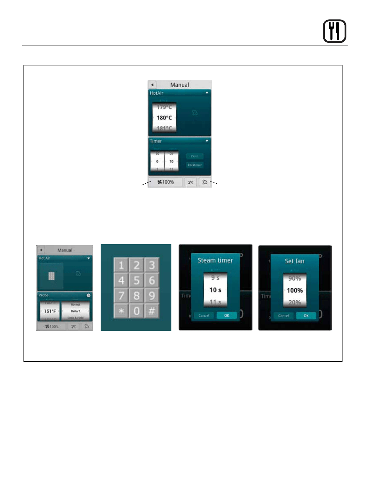
Operation
Hot Air Mode
Figure 10
Fan Speed
Vent Position
Steam
Injection
Steam Injection Timer
Setting the Fan Speed
Keypad Entry

20
Operation
Steaming is the ideal cooking mode for foods that can be
cooked in water.
NOTE: The temperature of the water in the steam
generator is checked automatically. For sanitary
reasons, if the water temperature is below 149°F
(65°C) the tank is emptied, relled and reheated.
Tips for Using the Steam Mode
• Prior to steaming, cool the oven to 175°F (80°C). To
lower the temperature quickly, use the Cool Down
mode and open the door.
• We recommend that you start the steaming process
8 minutes before loading the oven. For food safety,
the oven monitors the water in the steam generator.
If the water temperature is below 150°F (65°C), the
tank is emptied, relled and the water is heated.
Entering the Steam Mode
1. From the MAIN MENU, press the MANUAL key.
2. Select the STEAM mode.
Setting the Cook Time and Temperature
1. In the TEMPERATURE list, drag your nger up or
down to select the desired cook temperature. Refer
to table below for steaming temperature recommen-
dations.
To switch to keypad entry - Swipe your nger from
right to left across the upper portion of TEMPERA-
TURE scroll dial. Select the keypad icon from the
center of the box to bring up the keypad. Enter the
desired temperature. Press OK at the bottom of the
screen to set the temperature.
NOTE: To return to the scroll wheel, swipe the up-
per portion of keypad icon box from left to
right. The control defaults to the last entry
method used.
2. In the HOUR & MINUTES lists, drag your nger up or
down to set the desired cook time.
To switch to keypad entry - Swipe you nger from
right to left across the upper portion of TIMER scroll
dial. Select the keypad icon from the center of the box
to bring up the keypad. Enter the desired cook time
in hours and minutes. Press OK at the bottom of the
screen to set the timer.
3. When the cook time expires, the oven automatically
shuts off. Press the CONT. key if you want the oven
to continue operating after the set time has elapsed.
4. The oven starts automatically three seconds after the
cook time and temperature have been selected.
Setting the Fan Speed
The BCT has 9 fan speeds to choose from. You can set
the fan before or during the cook cycle.
1. To set the fan speed, press the FAN SPEED key in
the lower right corner of the screen.
2. Drag your nger up or down to set the fan speed in
increments of 10% (From 20-100%).
3. Press OK to save the fan speed.
Vent Position
The vent position is set automatically in the steam mode.
At the End of the Cook Cycle
1. When the cook time expires, an alarm sounds and
the display reads “Recipe Done!.
Press EXIT to end the cook cycle.
Press RESTART to continue the cook cycle.
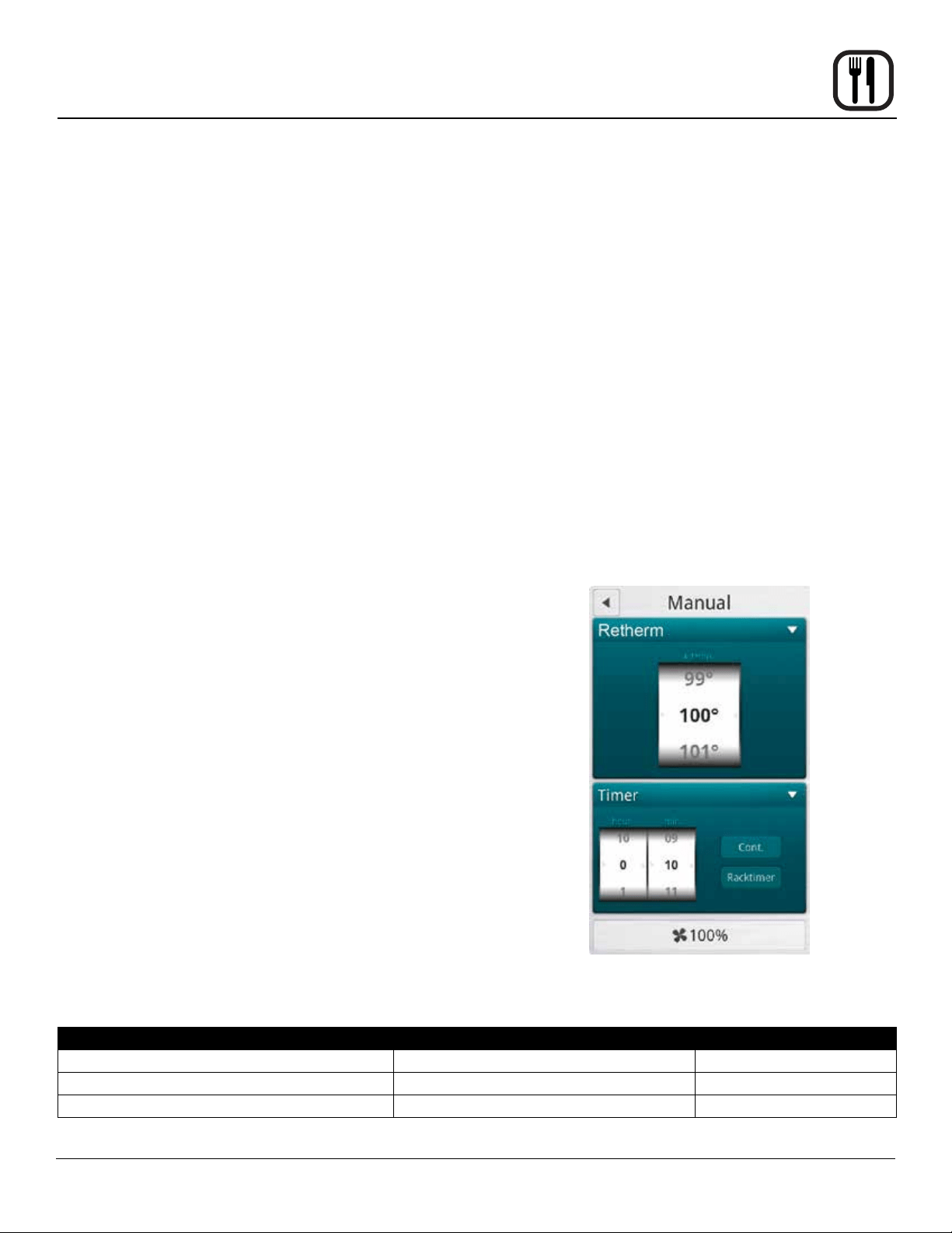
Figure 11
Steam Mode
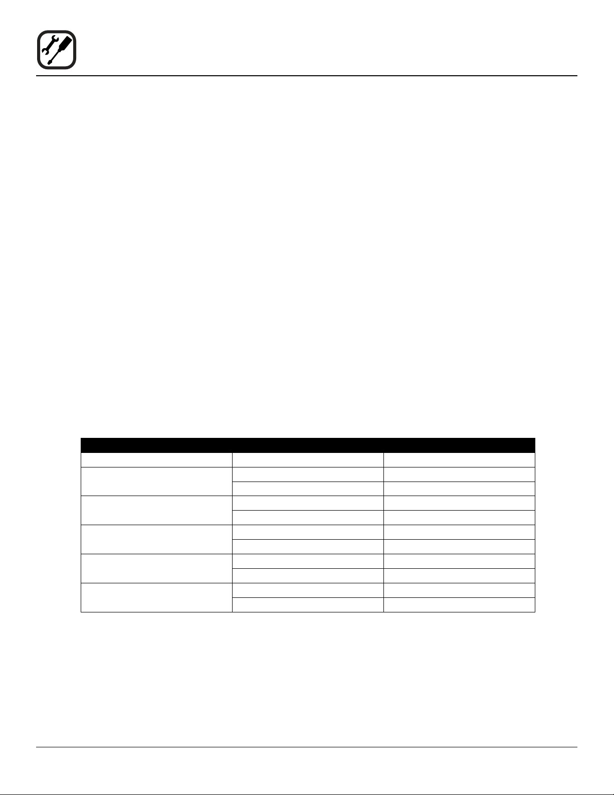
FUNCTION STEAM TEMPERATURE PRODUCTS
Low Temperature
Steaming
149-194°F (65-90°C) Fish and small vegetables. Steam small vegetables at 80°C for
5-10 minutes to keep their colour and crispness.
Traditional Steaming 208-212°F (98-100°C) Meat, pasta, potatoes, rice and root vegetables.
Forced Steaming 248°F (120°C) Vegetables that require further processing and for faster pro-
cessing of hard root and frozen vegetables, pasta and rice. Ex-
ercise caution when you use this function.
21
Operation
Retherm allows you to gently reheat previously prepared
products. During operation a carefully calculated amount
of humidity is added. This process helps maintain the ap-
pearance and avor of the product.
Tips for Successful Retherming
• For faster retherming, leave the product uncovered
during the reheating process.
• To reach the perfect end temperature, use the core
temperature probe. Refer to page 24 for informa-
tion on using the core probe.
• For retherm of sous-vide or similar products, follow
the supplier’s recommendations.
Entering the Retherm Mode
1. From the MAIN MENU, press the MANUAL key.
2. Select the RETHERM mode.
Setting the Retherm Time and Temperature
1. In the TEMPERATURE list, drag your nger up or
down to select the desired cook temperature.
To switch to keypad entry - Swipe your nger from
right to left across the upper portion of TEMPERA-
TURE scroll dial. Select the keypad icon from the
center of the box to bring up the keypad. Enter the
desired temperature. Press OK at the bottom of the
screen to set the temperature.
NOTE: To return to the scroll wheel, swipe the up-
per portion of keypad icon box from left to
right. The control defaults to the last entry
method used.
2. In the HOUR & MINUTES lists, drag your nger up or
down to set the desired cook time.
To switch to keypad entry - Swipe you nger from
right to left across the upper portion of TIMER scroll
dial. Select the keypad icon from the center of the box
to bring up the keypad. Enter the desired cook time
in hours and minutes. Press OK at the bottom of the
screen to set the timer.
3. When the cook time expires, the oven automatically
shuts off. Press the CONT. key if you want the oven
to continue operating after the set time has elapsed.
4. The oven starts automatically three seconds after the
cook time and temperature have been selected.
Setting the Fan Speed
The BCT has 9 fan speeds to choose from. You can set
the fan before or during the cook cycle.
1. To set the fan speed, press the FAN SPEED key in
the lower right corner of the screen.
2. Drag your nger up or down to set the fan speed in
increments of 10% (From 20-100%).
3. Press OK to save the fan speed.
Vent Position
The vent position is set automatically in the retherm mode.
At the End of the Cook Cycle
1. When the cook time expires, an alarm sounds and
the display reads “Recipe Done!.
Press EXIT to end the cook cycle.
Press RESTART to continue the cook cycle.
Figure 12
Retherm Mode
PRODUCTS RETHERM TEMPERATURE TIME
Rice, meat, and vegetables on a plate 284°F (140°C) 8-12 minutes
Whole roasts, stews, and sauces 248-384°F (120-140°C) 40-60 minutes
Pasta, rice, and similar 248°F (120°C) 20-30 minutes
22
Operation
CombiSmart Mode
The CombiSmart mode allows you to set an oven tem-
perature and select a preset humidity level. The oven
produces a consistent level of humidity. There is no com-
pensation for the moisture naturally found in the product.
Entering the CombiSmart Mode
1. From the MAIN MENU, press the MANUAL key.
2. Select the COMBI SMART mode.
Setting the Cook Time, Temperature and Humidity
NOTE: To ensure that the oven has reached the correct
humidity level, preheat the oven for 5 minutes at
the preferred humidity level.
1. In the TEMPERATURE list, drag your nger up or
down to select the desired cook temperature.
To switch to keypad entry - Swipe your nger from
right to left across the upper portion of TEMPERA-
TURE scroll dial. Select the keypad icon from the
center of the box to bring up the keypad. Enter the
desired temperature. Press OK at the bottom of the
screen to set the temperature.
NOTE: To return to the scroll wheel, swipe the up-
per portion of keypad icon box from left to
right. The control defaults to the last entry
method used.
2. In the STEAM list, drag your nger up or down to se-
lect the desired level of humidity. CombiSmart pro-
vides 10 different humidity levels. Refer to table be-
low for humidity level recommendations.
To switch to keypad entry - Swipe you nger from
right to left across the upper portion of STEAM scroll
dial. Select the keypad icon from the center of the box
to bring up the keypad. Enter the desired humitidy
level. Press OK at the bottom of the screen to set the
humidity.
NOTE: Humidity level must be entered in multiples
of 10 (10, 20, 30, etc).
3. In the HOUR & MINUTES lists, drag your nger up or
down to set the desired cook time.
To switch to keypad entry - Swipe you nger from
right to left across the upper portion of TIMER scroll
dial. Select the keypad icon from the center of the box
to bring up the keypad. Enter the desired cook time
in hours and minutes. Press OK at the bottom of the
screen to set the timer.
4. When the cook time expires, the oven automatically
shuts off. Press the CONT. key if you want the oven
to continue operating after the set time has elapsed.
5. The oven starts automatically three seconds after the
cook time, temperature and humidity have been se-
lected.
Setting the Fan Speed
The BCT has 9 fan speeds to choose from. You can set
the fan before or during the cook cycle.
1. To set the fan speed, press the FAN SPEED key in
the lower right corner of the screen.
2. Drag your nger up or down to set the fan speed in
increments of 10% (From 20-100%).
3. Press OK to save the fan speed.
Vent Position
The vent position is set automatically in the CombiSmart
mode.
At the End of the Cook Cycle
1. When the cook time expires, an alarm sounds and
the display reads “Recipe Done!.
Press EXIT to end the cook cycle.
Press RESTART to continue the cook cycle.
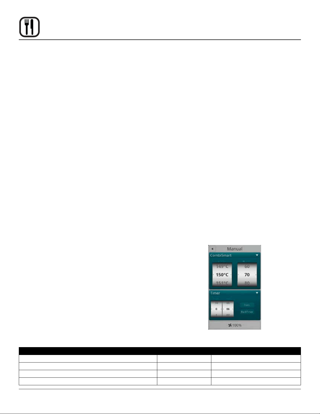
Figure 13
PRODUCTS HUMIDITY LEVEL TEMPERATURE
Dry air grilling 0 392-482°F (200-250°C)
Gravy production during braising of meat 70-80 293-329°F (145-165°C)
Poaching sh, poultry, and crispy vegetables 90-100 158-248°F (70-120°C)
Steaming potatoes, rice, pasta, meat, and more. 100 212°F (100°C) or steaming mode

23
Operation
CombiOptima Mode
NOTE: Not available on mini ovens.
CombiOptima allows you to set an oven temperature and
add a specic percentage of humidity. Many products
contain a large amount of water, increasing the humid-
ity level during cooking. In the CombiOptima mode the
oven automatically regulates the humidity to maintain the
desired level.
Tips for setting the humidity level
• To make gravy when braising meat, apply 70 to 80%
humidity at 300-325°F (145-65°C).
• For poaching sh, poultry and crispy vegetables, ap-
ply 70 to 95% humidity at 150-250°F (70-120°C).
• For short cook times and products, such as herb-
marinated cuts of meat and fresh vegetables, use
70% humidity at 375°F (190°C ).
Entering the CombiOptima Mode
1. From the MAIN MENU, press the MANUAL key.
2. Select the COMBI OPTIMA mode.
Setting the Cook Time, Temperature and Humidity
NOTE: To ensure that the oven has reached the correct
humidity level, preheat the oven for 5 minutes at
the preferred humidity level.
1. In the TEMPERATURE list, drag your nger up or
down to select the desired cook temperature.
To switch to keypad entry - Swipe your nger from
right to left across the upper portion of TEMPERA-
TURE scroll dial. Select the keypad icon from the
center of the box to bring up the keypad. Enter the
desired temperature. Press OK at the bottom of the
screen to set the temperature.
NOTE: To return to the scroll wheel, swipe the up-
per portion of keypad icon box from left to
right. The control defaults to the last entry
method used.
2. In the STEAM list, drag your nger up or down to se-
lect the desired percentage of humidity.
To switch to keypad entry - Swipe you nger from
right to left across the upper portion of STEAM scroll
dial. Select the keypad icon from the center of the box
to bring up the keypad. Enter the desired humitidy
level. Press OK at the bottom of the screen to set the
humidity.
NOTE: Humidity level must be entered in multiples
of 10 (10, 20, 30, etc).
3. In the HOUR & MINUTES lists, drag your nger up or
down to set the desired cook time.
To switch to keypad entry - Swipe you nger from
right to left across the upper portion of TIMER scroll
dial. Select the keypad icon from the center of the box
to bring up the keypad. Enter the desired cook time
in hours and minutes. Press OK at the bottom of the
screen to set the timer.
4. When the cook time expires, the oven automatically
shuts off. Press the CONT. key if you want the oven
to continue operating after the set time has elapsed.
5. The oven starts automatically three seconds after the
cook time, temperature and humidity have been se-
lected.
Setting the Fan Speed
The fan speed is set automatically in the CombiOptima
mode.
Vent Position
The vent position is set automatically in the CombiOptima
mode.
At the End of the Cook Cycle
1. When the cook time expires, an alarm sounds and
the display reads “Recipe Done!.
Press EXIT to end the cook cycle.
Press RESTART to continue the cook cycle.
Figure 14
24
Operation
All Blodgett BCT/BLCT ovens come standard with one
core temperature probe. It is possible to run two core
probes at the same time. An additional probe may be pur-
chased from your Blodgett dealer.
The core temperature sensor offers three cooking
modes.
• Normal
• Delta-T
• Cook & Hold
CORE PROBE MODES
Follow this procedure for all three core probe cook-
ing modes.
NOTE: The core probe must be set up prior to activating
a cook cycle.
1. Select the desired cooking mode. Refer to instruc-
tions on setting the cooking mode.
2. Set the desired fan speed if applicable. Refer to in-
structions on setting the fan speed.
3. Set the vent position if applicable. Refer to instruc-
tions on setting the vent position.
4. Insert the core probe into the center of the product.
Then plug the probe into the oven at the connector
located in the upper corner of the right side panel.
NOTE: Meat probes on mini combi models are
internal and do not need to be plugged into
the oven.
5. Press the ▼ key at the top of the timer list to display
the probe selection list.
6. Drag your nger up or down the Temp list to select the
desired core probe temperature.
7. Drag your nger up or down the Status list to select
the desired mode.
8. The oven starts automatically three seconds after the
core probe temperature and mode have been select-
ed.
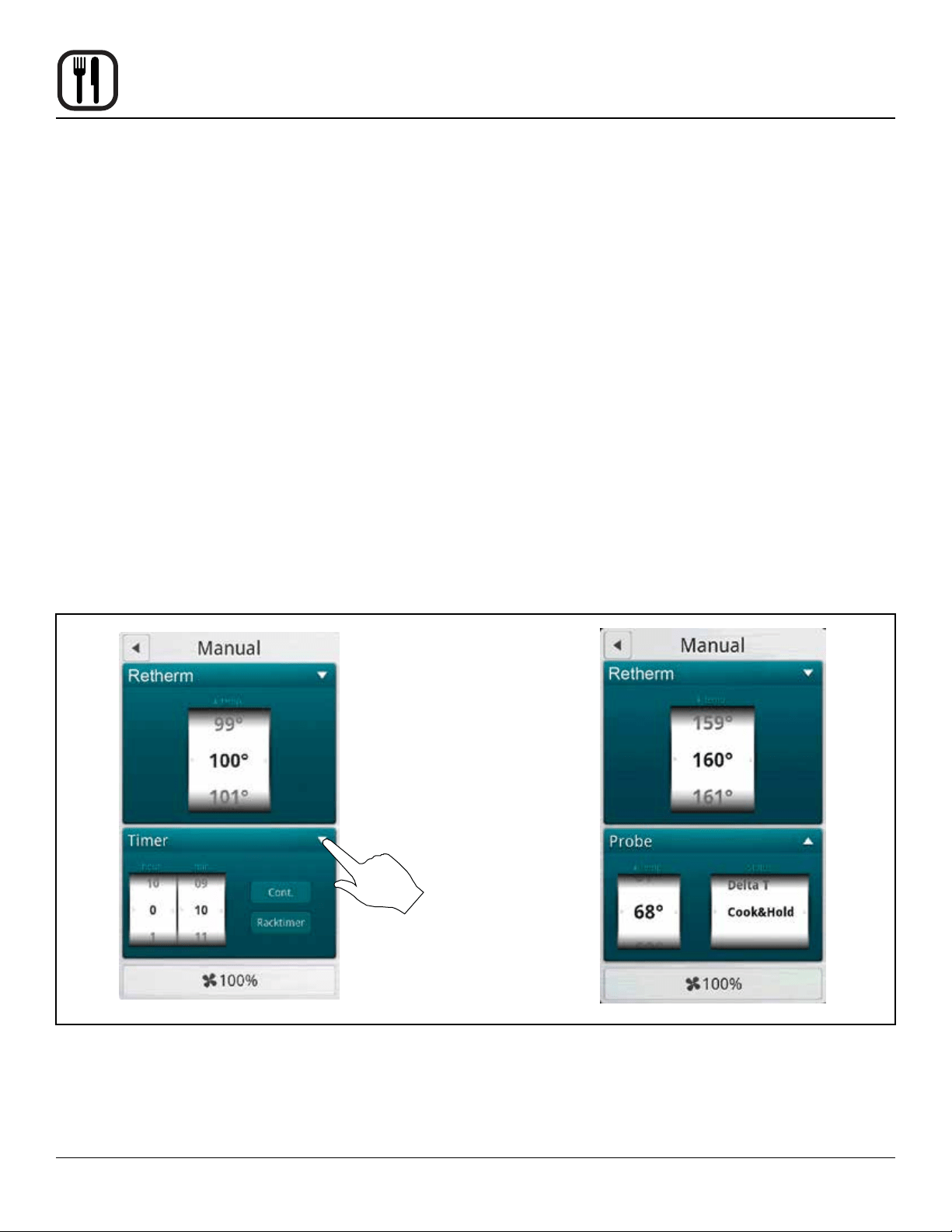
Using the Core Probe
Press to toggle between
timer and core probe
selection list
Retherm screens shown
Figure 15

25
Operation
Using the Core Probe
NORMAL CORE PROBE COOKING
In the normal mode, the core probe will notify you when
the product has reached the desired pull temperature.
The cook temperature is constant in the normal mode.
1. Follow steps 1-8 on page 24 to start a normal core
probe cook cycle.
2. The oven sounds an alarm, and turns off when the
specied core temperature has been reached.
Unplug the core probe and remove the product.
DELTA T
When you use Delta-T, the oven maintains a constant
difference in temperature between the core temperature
and the oven temperature. The temperature of the oven
rises slowly as the core temperature rises. Delta-T pro-
vides gentle cooking resulting in a tender, juicy product.
Cooking with Delta-T reduces shrinkage by up to 20%
compared to traditional modes of cooking.
1. Follow steps 1-8 on page 24 to start a Delta T cook
cycle.
2. The oven sounds an alarm, and turns off when the
specied core temperature has been reached.
3. Unplug the core probe and remove the product.
Tips for Delta-T Cooking
• For best results start with an oven temperature of
85-100°F (30-40°C).
• HOT AIR mode is recommended for very fatty and
small roasts. STEAM mode is recommended for
large hams with bones. RETHERM mode is recom-
mended for poultry and other lean pieces of meat.
Recommended Core Temperatures
• Rare 125-135°F (52-57°C)
• Medium 140-145°F (59-62°C)
• Well Done 160-185°F (72-85°C)
COOK & HOLD
Cook & Hold is an extension of Delta-T cooking. The oven
temperature adjusts relative to the actual core tempera-
ture of the product. When the desired core temperature is
reached, the oven adjusts the cavity to maintain the core
temperature, acting as a warming mode. Cook & hold is
suitable for roasting over night when the staff is off duty.
1. Follow steps 1-8 on page 24 to start a Cook & Hold
cycle.
2. When the product has reached the desired core tem-
perature the display will read HOLD??? and the oven
will adjust the cavity temperature to maintain the core
probe temperature.
3. Unplug the core probe and remove the product when
ready to serve.
Tips for Using Cook & Hold
• Recommended holding temperature is 140-150°F
(60-65°C). At higher temperatures a gradual dehy-
dration of proteins takes place, the weight of the
meat is reduced and the meat becomes less juicy.
• With a hold temperature of 140-150°F (60-65°C), the
meat can be taken out immediately before carving.
• After being held for 5-6 hours shrinkage increases.
26
Operation
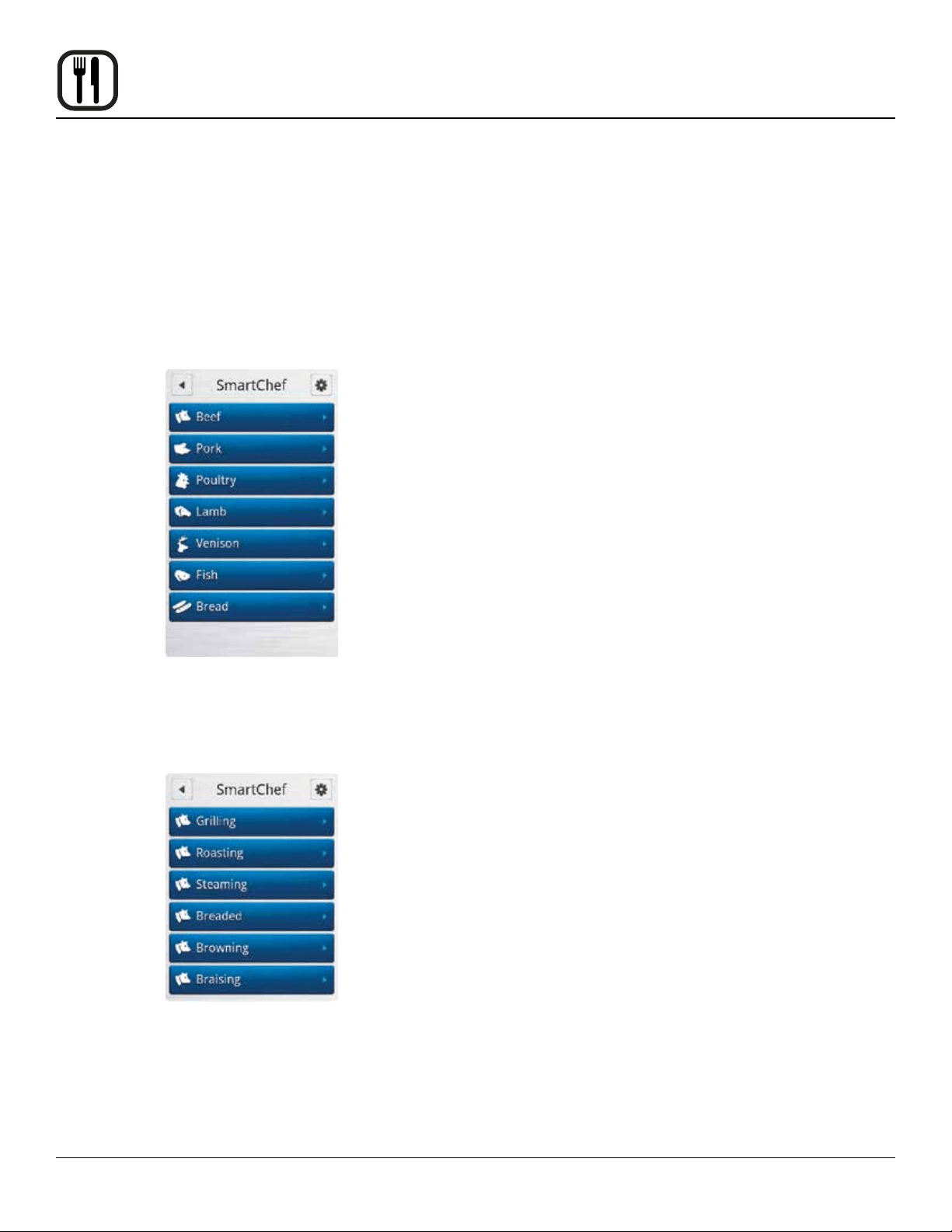
SmartChef Automatic Cooking
The SmartChef function provides a number of preset
cooking functions for a variety of products.
Entering the SmartChef Mode
1. From the MAIN MENU, press the MANUAL key.
2. Select the SMART CHEF mode.
Using the SmartChef Mode
1. Press the name of the type of product you are going
to cook.
Figure 16
2. The control displays the cooking modes programmed
for your product. Press the mode you want to use.
See table for list of available cooking modes.
Figure 17
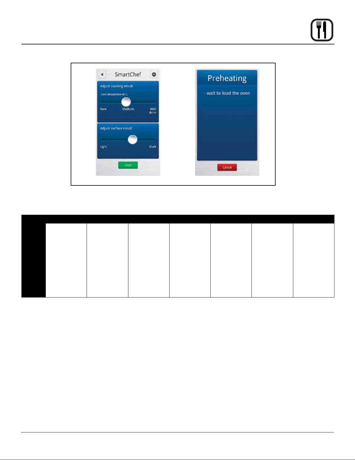
3. The control displays COOKING ADJUSTMENT SLID-
ERS. Make any adjustments you wish to achieve the
desired results.
a. Grilling - Slide the button to the left for rare meat
and to the right for well-done meat.
Slide the button to the left for a lighter result and
to the right for a darker result.
b. Steaming - Slide the button to the left for rare
meat and to the right for well-done meat.
Slide the button to the left for steaming at low
temperature
Slide the button to the right for forced steaming.
c. Braising - Slide the button to the left for rare
meat and to the right for well-done meat.
Slide the button to the left for a slow result and to
the right for a fast result.
Touch the Tender box if you want the oven to
keep the core temperature for 2 hours.
d. Browning - Slide the button to the left for shorter
cooking time and to the right for longer cooking
time.
Slide the button to the left for a lighter result and
to the right for a darker result.
e. Breaded - Slide the button to the left for rare
meat and to the right for well-done meat.
Slide the button to the left for thick breaded prod-
ucts and to the right for thin breaded products.
4. Press the START key when you have adjusted the
results. The oven begins the preheating process and
sounds an alarm, when the oven is ready.
27
Operation
SmartChef Automatic Cooking
BEEF PORK POULTRY LAMB VENISON FISH BREAD
AVAILABLE
ADJUSTMENTS
Grilling
Roasting
Steaming
Breaded
Browning
Braising
Grilling
Roasting
Steaming
Breaded
Browning
Braising
Crispy Skin
Grilling
Roasting
Steaming
Breaded
Browning -
Small Pieces
Braising
Dark Poultry
Grilling
Roasting
Steaming
Breaded
Browning
Braising
Grilling
Roasting
Steaming
Breaded
Browning
Braising
Grilling
Roasting
Steaming
Breaded
Baking
Baking Small
Size
Baking with
Steam
Puff Pastry
Figure 18
28
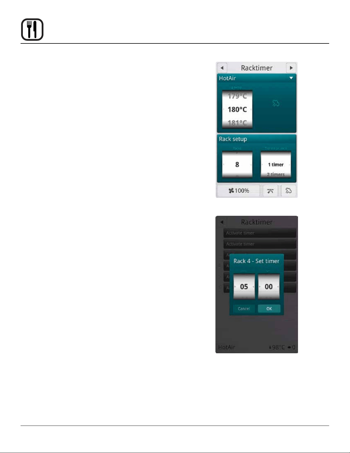
Operation
The rack timing function enables you to set one or more
timers for each individual rack. This way you can cook
different products on the same rack or on different racks
as long as they can use the same cooking mode. The
rack timer can be used in Hot Air, Combi, CombiOptima,
Retherm and Steam modes.
TO COOK USING RACK TIMING
1. From the MAIN MENU, press the MANUAL key.
2. Select the desired cooking mode. Set the cook tem-
perature and humidity level if applicable.
3. Press the RACK TIMER key.
4. In the RACK SETUP list, drag your nger up or down
to select the number of racks you want to associate
with the timer. You can choose between 1-10 racks.
5. In the TIMERS PER RACK list, drag your nger up or
down to select the number of timers you want to as-
sociate with the rack(s).
6. Push the arrow button in the upper right corner to
continue.
7. Push the ACTIVATE TIMER key for the rack timer you
wish to start.
8. In the HOUR & MINUTES lists, drag your nger up or
down to set the desired cook time.
9. Push the RIGHT ARROW key ► in the upper right
corner to start the timer.
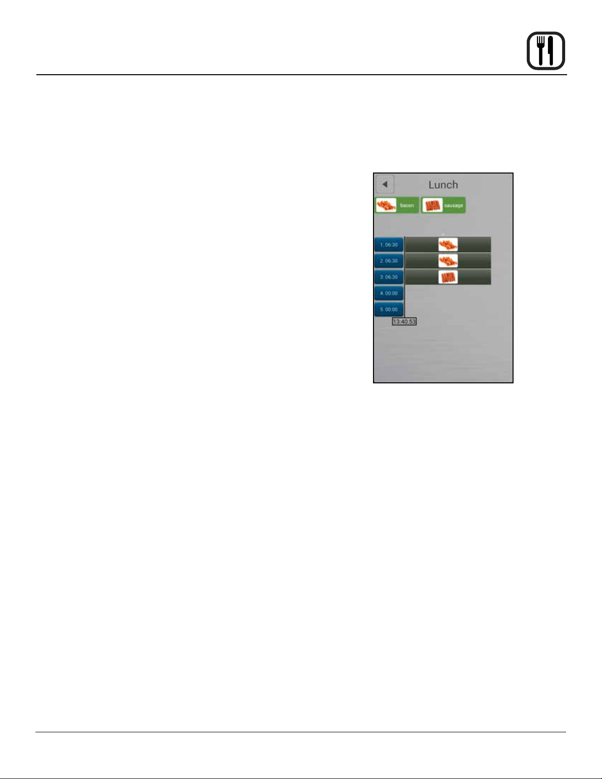
Blue buttons display the active timer settings and the
remaining time. The timer counts down to zero.
Yellow buttons display the active timer settings of
the timers that have reached the nal minute of the
countdown.
Green buttons and an alarm indicate that a rack timer
has nished its countdown. The display counts up the
time that has elapsed since the timer timed out.
10. Push the GREEN KEY to silence the alarm.
11. Push FINISH to end the timer.
Figure 19
Figure 20
Using Rack Timing

29
Operation
Using Advanced Rack Timing
The Advanced Rack Timer allows you to create groups
of recipes with similar characteristics (cook temperature,
humidity level, etc.). The advance rack timer cook screen
lets you manage multiple recipes of the same group si-
multaneously on separate racks of the oven.
Entering rack timer menus
1. From the MAIN MENU, press ADVANCED.
2. Select RACK TIMER.
SETTING UP GROUPS & RECIPES
Creating a Recipe Group
NOTE: Up to 18 recipes can be assigned to a single
group. In order for recipes to be grouped to-
gether they must have the same cook mode, and
similar temperature settings.
1. To create a recipe group select the + key at the bot-
tom of the screen. This will bring you to the SETUP
GROUP screen.
2. Select NAME BAR to edit the group name. Use the
keypad to enter a group name. Press the right arrow
► key in the upper right hand corner of the screen to
save and return to the SETUP GROUP screen.
3. Select the camera icon in the IMAGE BAR to associ-
ate a picture with the group. Press OK to save the
selection and return to the SETUP GROUP screen.
4. Under RECIPES you can select existing recipes to
add to the group. Once a recipe has been selected a
green check mark will appear to the right indicating it
is part of the group. To remove a recipe, select it again
and the check mark will be removed. To add a new
recipe, see Creating a Recipe.
NOTE: The rst selected recipe will dene the set-
tings for the group. Recipes that have set-
tings incompatible with the group’s settings
will be grayed out.
5. When all desired recipes have been selected, press
the right arrow ► key in the top right corner to save
the group and return to the RACK TIMER MENU.
Name Bar
Image Bar
Create Recipe
Figure 21
Editing a Group
1. In RACK TIMER MENU screen, press and hold the
group’s icon. A box will appear allowing you to edit or
delete the group.

30
Operation
Creating a Recipe
1. Select the + key from the bottom of the SETUP
GROUP screen.
2. Select the NAME BAR to edit the group name. Use
the keypad to enter a recipe name. Press the right
arrow ► key in the upper right hand corner of the
screen to save and return to the SETUP RECIPE
screen.
3. Select the COLOR BAR to associate a color with the
recipe. Press OK to save the selection and return to
the SETUP RECIPE screen.
4. Select the camera icon in the IMAGE BAR to asso-
ciate a picture with the recip. Press OK to save the
selection and return to the SETUP RECIPE screen.
Select the SETTINGS BAR below the image bar to edit
the temperature, cook mode, fan speed, vent state, and
cook time of the recipe. Press the right arrow ► key in the
upper right hand corner of the screen to save the recipe
settings and return to the SETUP RECIPE screen.
Editing a Recipe
In SETUP GROUP screen, press and hold the recipes’
icon. A box will appear allowing you to edit or delete the
recipe.
Name
Bar
Color
Bar
Image
Bar
Settings
Bar
Figure 22
Selecting a Group
1. From the RACK TIMER MENU screen, select the
number of racks you’d like to use and the group with
recipes you wish to use. Then select the right arrow
► key in the upper right hand corner to enter the
RACK TIMER COOK screen.
2. To select a new group, return to the RACK TIMER
MENU screen from the RACK TIMER COOK screen
by selecting the left arrow◄ key in the top left of the
screen.
Using Advanced Rack Timing
31
Operation
Using Advanced Rack Timing
COOKING WITH RACK TIMER
NOTE: The top portion of the RACK TIMER COOK
screen contains the recipes in your group. If
there are more than 6 recipes in your group
you can browse the other recipes by swiping
the screen from right to left in this portion of the
screen. To return to the previous 6 recipes sim-
ply swipe in the reverse direction. The highlight-
ed circle below the recipes indicates what page
(of up to 3) you are currently on.
Assigning a Recipe – Click
1. Select the blue timer box associated with the rack
number you’d like to place a recipe on, it will become
highlighted.
2. Select the recipe icon from the top of the screen as-
sociated with the recipe you’d like to place on the se-
lected rack, it will become highlighted.
3. Reselect the highlighted timer box to assign the reci-
pe to the rack.
Assigning a Recipe – Drag and Drop
1. Press and hold the desired recipes’ icon for approxi-
mately 2 seconds.
2. Drag recipe to desired rack location.
Starting a recipe
1. Once a recipe has been added to a rack the unit will
begin preheating to the required temperature. Pre-
heating is indicated by a red thermometer icon to the
right side of the screen. Once preheated the icon will
change to an orange “load” icon.
2. The recipe timer will automatically start when the
oven has preheated and the product has been loaded
into the oven (door opened/closed).
Remove Recipes – Drag and drop
1. Press and hold the recipe bar on a rack until a trash
can appears to the right.
2. Drag the recipe to the trash can.
Figure 23

32
Operation
The Advanced Menu gives you access to the PreHeat,
CoolDown and Proong functions.
PREHEAT
Use PreHeat to preheat the oven prior to cooking.
1. From the MAIN MENU, press the ADVANCED key.
2. Select the PREHEAT mode.
3. The PreHeat temperature list is displayed. Drag your
nger up or down to set the desired temperature.
To switch to keypad entry - Swipe your nger from
right to left across the upper portion of TEMPERA-
TURE scroll dial. Select the keypad icon from the
center of the box to bring up the keypad. Enter the
desired temperature. Press OK at the bottom of the
screen to set the temperature.
NOTE: To return to the scroll wheel, swipe the up-
per portion of keypad icon box from left to
right. The control defaults to the last entry
method used.
4. The oven begins preheating automatically three sec-
onds after the temperature has been selected.
COOL DOWN
Use this function to quickly cool the oven cavity. For the
best results, set the cool down temperature 68°F (20°C)
lower than the desired cooking temperature.
1. From the MAIN MENU, press the ADVANCED key.
2. Select the COOL DOWN mode.
3. The Cool Down temperature list is displayed. Drag
your nger up or down to set the desired cool down
temperature.
To switch to keypad entry - Swipe your nger from
right to left across the upper portion of TEMPERA-
TURE scroll dial. Select the keypad icon from the
center of the box to bring up the keypad. Enter the
desired temperature. Press OK at the bottom of the
screen to set the temperature.
4. The oven begins cooling down automatically three
seconds after the temperature has been selected.
Figure 24
PreHeat, Cool Down and Proong

33
Operation
PreHeat, Cool Down and Proong
PROOFING
NOTE: Prebaked products do not need proong.
1. From the MAIN MENU, press the Advanced key.
2. Select the PROOFING mode.
3. The PROOFING TEMPERATURE list and timer are
displayed. Drag your nger up or down to set the de-
sired proong temperature.
To switch to keypad entry - Swipe your nger from
right to left across the upper portion of TEMPERA-
TURE scroll dial. Select the keypad icon from the
center of the box to bring up the keypad. Enter the
desired temperature. Press OK at the bottom of the
screen to set the temperature.
4. In the HOUR & MINUTES lists, drag your nger up or
down to set the proong time.
To switch to keypad entry - Swipe you nger from
right to left across the upper portion of TIMER scroll
dial. Select the keypad icon from the center of the box
to bring up the keypad. Enter the desired cook time
in hours and minutes. Press OK at the bottom of the
screen to set the timer.
5. When the cook time expires, the oven automatically
shuts off. Press the CONT. key if you want the oven
to continue operating after the set time has elapsed.
6. The oven starts automatically three seconds after the
cook time, temperature and humidity have been se-
lected.
Figure 25
Setting the Fan Speed
The BCT has 9 fan speeds to choose from. You can set
the fan before or during the cook cycle.
1. To set the fan speed, press the FAN SPEED key in
the lower right corner of the screen.
2. Drag your nger up or down to set the fan speed in
increments of 10% (From 20-100%).
3. Press OK to save the fan speed.
At the End of the Proof Cycle
1. When the proof time expires, an alarm sounds and
the display reads “Recipe Done!.
Press EXIT to end the proof cycle.
Press RESTART to continue the proof cycle.

34
Maintenance
Cook to Perfection
The cook to perfection function helps recipes compen-
sate for temperature uctuations. These can occur when
transitioning between recipes with different temperatures,
opening the door, or adding frozen products. The system
makes real time adjustments to cook time ensuring qual-
ity cooking.
CTP threshold (%)
CTP threshold accounts for when the cavity temperature
is below the recipe set temperature. Time will be added
to the recipe as long as the cavity temperature remains
below the CTP threshold percent of temperature.
EXAMPLE: The oven preheats to a recipe’s set tempera-
ture of 350°F and a frozen product is loaded. The temper-
ature of the frozen product and opening the door causes
the cavity temperature to drop to 230°F. The CTP will be-
gin extending the total recipe time as long as the cavity
temperature remains below the programmed threshold
value, at 80% this equates to 285°F. This compensates
for the time it takes the oven to recover to the 350°F
called for in the recipe.
CTP tolerance (°)
The CTP tolerance value is a temperature range. If the
oven’s measured temperature is outside the range of the
desired temperature, the unit will adjust cook times. Un-
like the threshold value, the tolerance compensates when
the oven is too high above set point as well as below set
point by adding or subtracting time as needed.
EXAMPLE: Using the same example of 350°F, a 15° tol-
erance means that time will be added to the recipe as
long as the cavity is lower than 335°F and subtract if cav-
ity achieves temperatures above 365°F. This may be the
case if you go from a recipe with a higher set temperature
to a lower temperature without allowing the oven to cool.
To set up Cook To Perfection (CTP)
1. From the MAIN MENU select the GEAR ICON.
2. Select SUPER USER from the SETTINGS MENU.
3. Select SETTINGS from the SUPER USER MENU.
4. Select COOK TO PERFECTION and set to YES to
enable.
5. Select CTP THRESHOLD. Enter the percentage of
set temperature you would like CTP to use for a tem-
perature threshold.
6. Select CTP TOLERANCE. Enter the temperature you
would like CTP to use for a temperature tolerance.
Figure 26
35
Operation
Programmed Cooking
Programmed cooking is simple in the Blodgett BCT Com-
bi. Choose from one of a wide variety of pre-programmed
recipes or create your own.
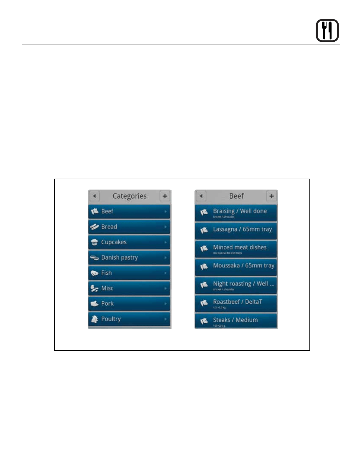
Use an Existing Program Recipe
1. From the MAIN MENU, press the RECIPES key. The
CATEGORIES menu is displayed.
2. Press the desired product category.
3. Press the desired product. The programming details
for the selected product are listed. If you want to ad-
just the recipe, press the gear wheel icon in the top
right corner of the screen. Follow the steps described
in Adding New Recipe Program (page 36).
4. Press START to initiate the cook cycle.
At the End of the Cook Cycle
1. When the cook time expires, an alarm sounds and
the display reads “Recipe Done!.
Press EXIT to end the cook cycle.
Press RESTART to continue the cook cycle.
Figure 27
Category Screen Product Screen

36
Operation
1. From the MAIN MENU, press the RECIPES key. The
CATEGORIES menu is displayed.
2. To add a new recipe, press the + in the upper right
corner of the screen.
3. The CHOOSE CATEGORY screen is displayed. Drag
your nger up or down to select the desired product
category. Press the right arrow key ► to save and
advance to the next screen.
4. To name the new recipe, press right arrow key ► in
the TITLE/DESCRIPTION BOX. Use the keyboard to
enter a name and a description of the new recipe.
Press the right arrow key ► to save and advance to
the next screen.
5. Touch the FAVORITE key if you want to add the reci-
pe to your list of favorites.
6. Press the ADD STEP key to add the rst step of the
cooking process.
7. In the SELECT STEP TYPE list drag your nger up or
down to select the desired cooking mode. Press the
right arrow key ► to save and advance to the next
screen.
8. Choose the desired cook settings for the step. Press
the right arrow key ► to save your settings.
9. Add as many steps as needed.
More Functions
• If you want to change the recipe category, press the
MORE FUNCTION key at the bottom of the screen.
Then press CHANGE CATEGORY. You can then
choose a different category.
• To make a copy of the recipe, press the MORE
FUNCTION key at the bottom of the screen. Then
press DUPLICATE RECIPE. The Copying Recipe
message appears. You can then edit the copy.
• To delete the recipe, , press the MORE FUNCTION
key at the bottom of the screen. Then press DE-
LETE RECIPE. Press Yes to delete the recipe.
Adding a New Recipe Program
Choose Category Name Recipe
Select Cooking Mode
Figure 28

37
Operation
Favorites
Using Favorites
1. From the MAIN MENU, press the FAVORITES key.
2. Press the desired recipe. The recipes are listed in al-
phabetical order. All the steps of the recipe, and the
total cooking time are displayed.
3. Touch the START key, to start the oven. The oven
starts the preheating process, and displays “load the
oven”, when the oven is ready.
Adding a Recipe to Favorites
1. From the MAIN MENU, press the RECIPES key.
2. Select the category for the recipe you wish to add to
the favorites list.
3. Press the name of the recipe you wish to add to the
favorites list.
4. Press the gear wheel icon in the upper right corner of
the screen.
5. Press the FAVORITE key so that it changes to YES.
6. Press the right arrow ► key in the upper right corner
to save your recipe to the favorites list.
Figure 29

38
Operation
USB
The Blodgett BCT/BLCT comes standard with a USB port
located underneath the control compartment. The USB
will enable upload and download of product recipes as
well as HACCP data.
To Access USB Menu
1. Insert the USB card into the slot below the control
compartment.
2. From the MAIN MENU, press the ADVANCED key.
3. Press the USB key. The control displays the following
options:
• Import Recipes - from USB to Oven
• Export Recipes - from Oven to USB
To Import Recipes from the USB to the Oven
1. Press Import Recipes.
2. All recipe les currently on the USB drive will be dis-
played. Select the desired recipe le.
3. Select either All Recipes or the appropriate product
category. Select the recipes you wish to upload to the
oven.
If All Recipes is selected, you may choose any or all
of the recipes on the USB drive.
If a category is selected, you may choose any or all of
the recipes in that category.
4. Press the USB icon in the upper right corner of the
screen.
5. If you are overwriting a le currently on the oven, a
screen is displayed requesting you acknowledge the
overwrite.
6. Next the uploading screen appears. When the upload
is complete, a green success screen is displayed.
Press Finish.
7. The control returns to the USB screen.
To Export Recipes from the Oven to the USB
1. Press Export Recipes.
2. Select either All Recipes or the appropriate product
category. Select the recipes you wish to upload to the
oven.
If All Recipes is selected, you may choose any or all
of the recipes on the USB drive.
If a category is selected, you may choose any or all of
the recipes in that category.
3. Press the USB icon in the upper right corner of the
screen.
4. The Enter Filename screen is displayed. Use the key-
board to name the le. Press the Done key at the bot-
tom of the keyboard to save the lename.
5. Press the right arrow key ► in the top right corner.
The upload begins automatically.
6. The green success box is displayed. Press Finish.
7. The control returns to the USB screen.

39
Operation
USB
To Import and Export Groups and Recipe Files in Ad-
vance Rack Timer
NOTE: Importing - you will be given the option to select
the desired recipe le on the USB drive. Once a
recipe set has been selected you will be given
the option to overwrite the existing recipe le
with those on the USB or append them to the
current recipe library.
Exporting – you will be prompted to name the
recipe library being exported.
1. From the MAIN MENU, press ADVANCED.
2. Select RACK TIMER.
3. In the RACK TIMER MENU screen select the BACK-
UP key from the bottom left hand corner of the screen.
4. Insert the USB drive you wish to copy the les to or
from into the port located at the front of the unit.
5. Select whether you would like to import or export the
recipes.
NOTE: Importing will overwrite any existing groups
and recipes.
6. Follow onscreen prompts to complete import or ex-
port of recipe les.
7. A notication will appear when le transfer is com-
plete. Select “Finish” to exit the pop-up screen.
USB Main Screen
Figure 30
USB Recipe Screen
USB Advanced Rack Timing Screens
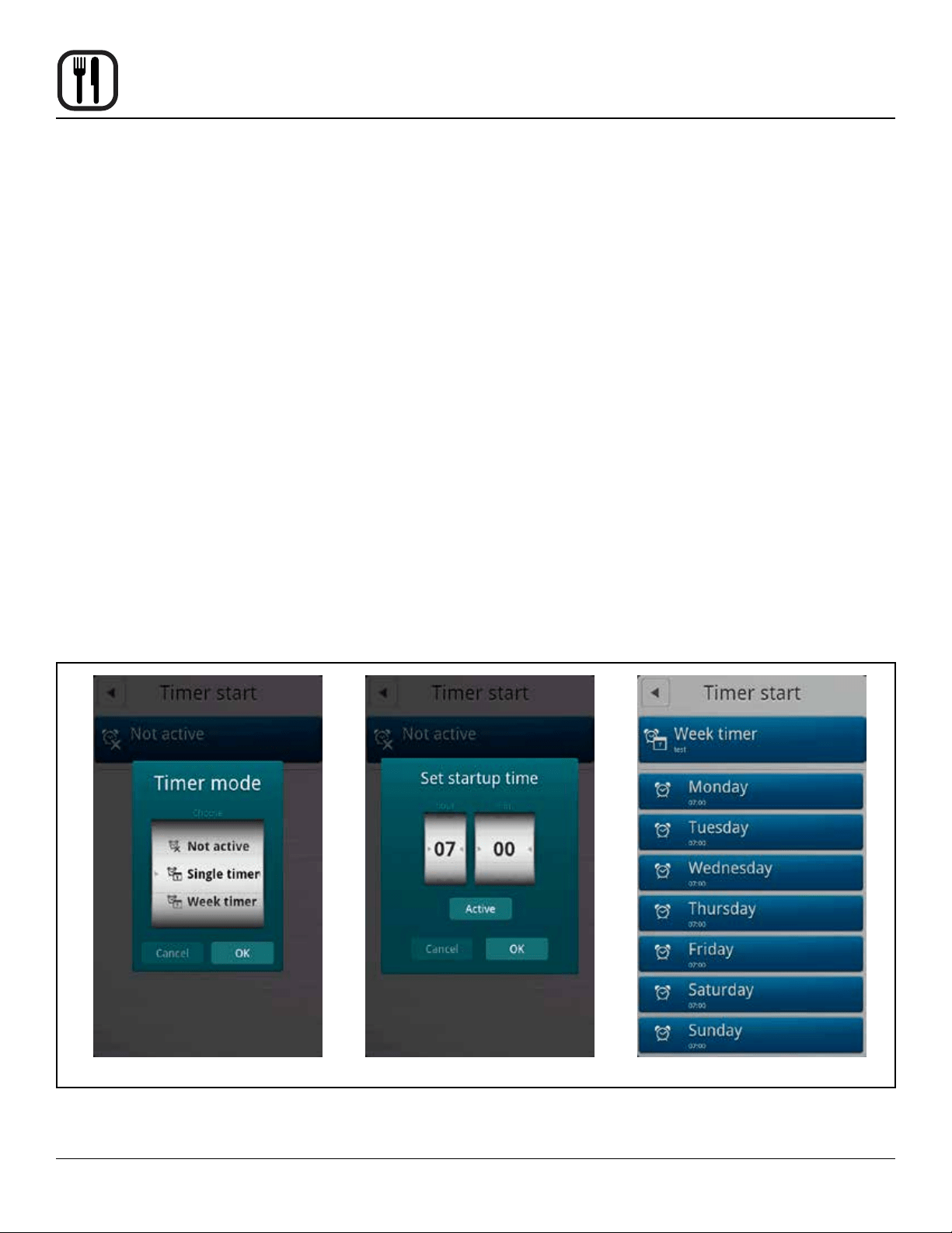
40
Operation
Timed Start
Timed Start makes it possible to start the oven using any
programmed recipe before staff arrives. This way, the
oven will be hot when you come in in the morning.
1. From the MAIN MENU, press the ADVANCED key.
2. Press the TIMED START key. The control displays
the current timed start.
3. Press the TIMED START box.
4. Drag your nger up or down to select the desired
timed start. Choose from:
• Non-Active - no timed start
• Single Timer - use for a single occurence timed
start
• Weekly Timer - use to set a timed start for each
day of the week.
Programming a Single Timed Start
1. Select Single Timer and press OK.
2. Enter the desired start time. Press OK.
3. The control displays the category list. Select the ap-
propriate product category.
4. Select the desired product recipe.
5. The display shows Single Timer with the recipe name
in the top box and the start time in the second box.
You may edit either start time or recipe by touching
either box.
6. Push the left arrow key ◄ to return to the advanced
menu.
Programming a Weekly Timed Start
1. Select Weekly Timer and press OK.
2. Enter the desired start time. Press OK.
3. The control displays the category list. Select the ap-
propriate product category.
4. Select the desired product recipe.
5. The display shows Week Timer with the recipe name
in the top box, followed by seven boxes, one for each
day of the week with the start time.
You may edit the start time for each day individually
by touching the box for that day.
6. Push the left arrow key ◄ to return to the advanced
menu.
SelectingTimer Mode
Figure 31
Setting a Single Timer
Setting a Week Timer

41
Maintenance
HACCP Library
The Blodgett BCP/BLCP comes standard with HACCP
data recording. HACCP enables you to control and docu-
ment production. Data recorded includes production time.
production duration, preparation temperature and core
temperature.
The HACCP library can hold approximately 1000 log les.
You will be notied when the memory is full so that you
can empty the memory with the USB. If nothing is done,
the computer will automatically start to overwrite the old-
est les.
To Activate HACCP Data Recording
NOTE: HACCP data is stored under product recipe
names. Therefore, HACCP is not available for
manual cooking.
HACCP must be activated to record data.
1. From the MAIN MENU, press the GEAR key.
2. Press the SUPER USER key.
3. Press the SETTINGS key.
4. Press the HACCP LOGGING key.
5. Drag your nger up or down to select YES. Press OK
to enable HACCP recording.
To View HACCP Data
1. From the MAIN MENU, press the ADVANCED key.
2. Press the HACCP key.
3. From the HACCP menu, press the key labelled either
Show HACCP from Oven or Show HACCP from USB.
4. A list of HACCP log les is displayed. The les are
logged by year, month, date and product name. Use
the UP and DOWN ARROW keys to scroll through the
list until the desired HACCP le is highlighted.
5. Press the OK key in the upper right of the control to
display the HACCP chart.
6. Press the RETURN key at the top left of the screen to
return to the HACCP screen.
To Backup HACCP Data
1. From the HACCP menu, press the key labelled Ar-
chive on USB.
2. The display reads SAVING HACCP.
3. When the data is saved to the USB the control returns
to the HACCP screen.
NOTE: The HACCP data on the USB can be lo-
cated in the folder with the serial number.
To Delete HACCP Data from the Oven
1. From the HACCP menu, press the key labelled De-
lete HACCP Data from Oven.
2. The screen will ask you to conrm that you want to
delete all HACCP les. Press the key next to Accept
to delete the les. Press the key next to Regret to
cancel.
3. The control returns to the HACCP screen.
42
Maintenance
Cleaning & Preventative Maintenance
DAILY CLEANING
Daily cleaning of your Combi oven is essential for sanita-
tion, and to ensure against operational difculties.
Cleaning the Exterior
1. The exterior of the appliance may be cleaned and
kept in good condition with a light oil. Saturate a cloth
and wipe the appliance when it is cold; wipe dry with
a clean cloth.
WARNING!!
DO NOT spray the outside of the appliance
with water or clean with a water jet. Cleaning
with a water jet can impregnate chlorides into
the stainless steel, causing the onset of corro-
sion.
Cleaning the Interior
NOTE: DO NOT use corrosive cleaners not intended for
oven cleaning on your Combi oven.
Blodgett recommends the following products for cleaning
and rinsing of your Blodgett Combi oven. If you choose
to use products other than what Blodgett recommends,
please have your suppler send us the MSDS sheet on the
proposed alternate so we can ensure it meets our stan-
dards. Non approved products can cause harm to your
unit and can potentially void your warranty.
1. Open the oven door.
2. Use the attached spray hose, located beneath the
control, to clean the front drip tray. Water will run to
the drain in the oven cavity.
RECOMMENDED OVEN CLEANERS
VENDOR PRODUCT NAME
1st AYD Corporation Kombi-Klean Oven, Grill &
Fryer Cleaner
Alco Chemical 350 Ultra Cycle
Daley International Oven & Grill Cleaner
Ecolab Keystone Oven Cleaner
Oven Cleaner Power
Grease Cutter Plus
Specialty Oven Cleaner
Ecotemp Ultra Kleene
Proforce Oven Grill & Fryer
Cleaner
Johnson Diversey Suma Grill D9
Kay Chemical Empire Inside/Outside
Degreaser
Parkside Pro Products Vestec 550
PDQ Manufacturing Comi-Clean
Performance Food
Group
First Mark All Temp Dish
Machine Detergent
U.S. Chemical Heavy Duty Oven & Grill
Cleaner
RECOMMENDED RINSE AIDS
VENDOR PRODUCT NAME
Alco Chemical 320 Rapid Rinse
Ecolab Keystone Liquid Rinse Additive
Oven Rinse Power
Esteem Dry-All
Eco Temp Ultra Dry
Specialty Oven Rinse RTU
Specialty Oven Rinse
Johnson Diversey Suma Maro A8.8
Suma Nova L6
Parkside Pro
Products
Vestec 510
PDQ Manufacturing Combi-Rinse
Performance Food
Group
First Mark Kleer Kwick Plus
Quick Dry Rinse Aid
U.S. Chemical Heavy Duty Rinse Agent
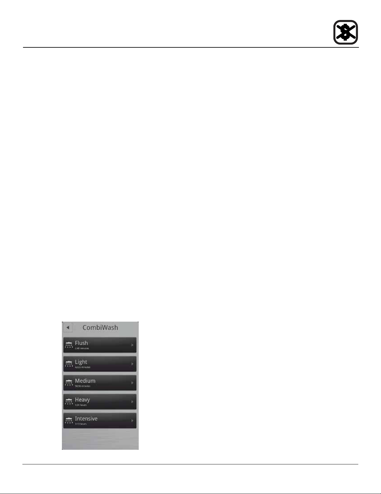
43
Maintenance
Cleaning & Preventative Maintenance
Run the CombiWash automatic cleaning cycle as fol-
lows:
1. Check the level of detergent and rinse aid in the con-
tainers. The red tube is for detergent and the blue
tube is for rinse aid.
Check that the oven temperature is below 80°C. If the
oven is too hot, use the CoolDown function (see page
page 32).
2. On the MAIN MENU press the MANUAL key.
3. Press the COMBI WASH key.
4. Touch the desired cleaning mode. You can choose
between the following cleaning cycles.
• Flush: Use this before starting the other clean-
ing programs.
• Light: Use this after steaming and roasting at
low temperatures.
• Medium: Use this after steaming and roasting at
medium temperatures.
• Heavy: Use this after roasting at temperatures
higher than 180°C.
• Intensive: Use this after roasting very greasy
products.
5. Press Start to initiate CombiWash.
Note: If the cleaning cycle is interrupted before it has
been completed, for example because of a
power outage, the oven automatically performs a
safety ush to remove any detergent remnants.
Figure 32
WEEKLY CLEANING
In addition to the daily cleaning, it is necessary to clean
the control lter and behind the fan guard on a weekly ba-
sis. This is necessary for proper functioning of the oven.
Scale will build up on the fan and heat source leading to
a less efcient oven.
Cleaning the Control Filter
NOTE: Not applicable on mini combi ovens.
The control lter is located below the control compart-
ment, in front of the spray hose.
1. To remove, pull down on the black knob on the left of
the lter.
2. Clean the lter with soap and water.
3. Reinstall the lter. Press up on the lter until the back
of the knob is inserted into the hole in the bottom of
the oven.
4. Push up on the center of the knob to expand the back
of the knob securing the lter.
Cleaning Behind the Fan Guard
1. Loosen the two screws and on the fan guard (or baf-
e).
2. Swing the bafe forward.
3. Thoroughly spray cleaner onto the fan and heat
source. Place the oven in the steam mode for ap-
proximately 10 minutes.
4. After ten minutes, rinse the cleaner off. Return the fan
guard to the closed position. Rotate the two screws to
secure the fan guard.
PREVENTIVE MAINTENANCE
The best preventive maintenance measures are the
proper initial installation of the equipment and a
program for cleaning the appliance routinely. The Oven/
Steamer requires no lubrication. Contact the factory, the
factory representative or a local Blodgett Combi service
company to perform maintenance and repairs should they
be required.
44
Maintenance
Deliming - BCT only
The control keeps track of boiler usage between deliming.
When the oven has reached 95% of the time the control
warns the operator that the oven needs to be delimed.
This is a warning only, the oven can be used all day be-
fore deliming.
Deliming the Oven
1. Be sure the container delivering the deliming agent
to the appliance is full. Be sure to use a non-diluted
deliming agent.
VENDOR PRODUCT NAME
Ecolab Keystone Lime-a-way
scale remover
Calibre
Parkside Pro Products Vestec 691
2. From the MAIN Menu, press the GEAR ICON.
3. The control displays the SETTINGS menu. Press the
SUPER USER key.
4. The control display the Super User screen. Press the
DELIME PROGRAM key.
5. The control displays the Delime screen. Press the
DELIME key. The control asks if the oven is empty.
Press YES to start the deliming process or NO to
empty the oven. If NO is pressed, the control returns
to the previous screen.
6. The remainder of the process is automatic. The con-
trol displays the deliming steps as they occur.
To stop the deliming process, press the STOP key.
The control returns to the Super User screen.
NOTE: The oven can be delimed at any time.
7. When the nal delime stage is complete the control
displays DELIME DONE. Press OK to return to the
Super User screen.
Flushing the Boiler
The boiler may be ushed to ensure there is no descaling
agent is present.
1. From the MAIN Menu, press the GEAR ICON.
2. The control displays the SETTINGS menu. Press the
SUPER USER key.
3. The control display the Super User screen. Press the
DELIME PROGRAM key.
4. The control displays the Delime screen. Press the
DELIME FLUSH key. The control asks if the oven is
empty.
Press YES to ush the boiler or NO to empty the
oven. If NO is pressed, the control returns to the pre-
vious screen.
5. The remainder of the process is automatic. The con-
trol displays the deliming ush steps as they occur.
To stop the deliming process, press the STOP key.
The control returns to the Super User screen.
NOTE: The oven can be delimed at any time.
6. When the nal delime stage is complete the control
displays DELIME DONE. Press OK to return to the
Super User screen.
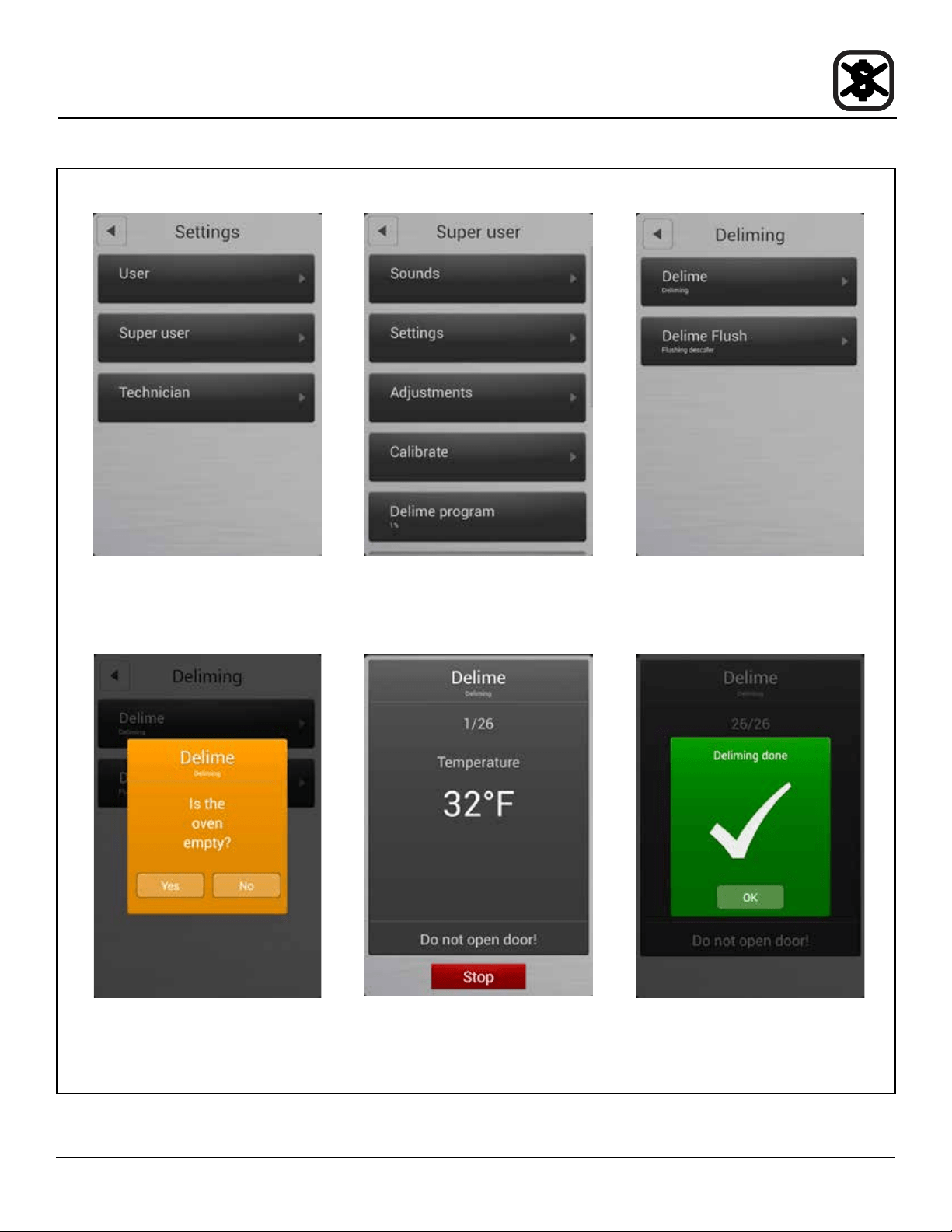
45
Maintenance
Deliming - BCT only
Settings Menu
Figure 33
Super User Screen Delime Screen
Conrm the oven is empty Delime running screen Delime done screen