Loading ...
Loading ...
Loading ...
8
ASSEMBLY
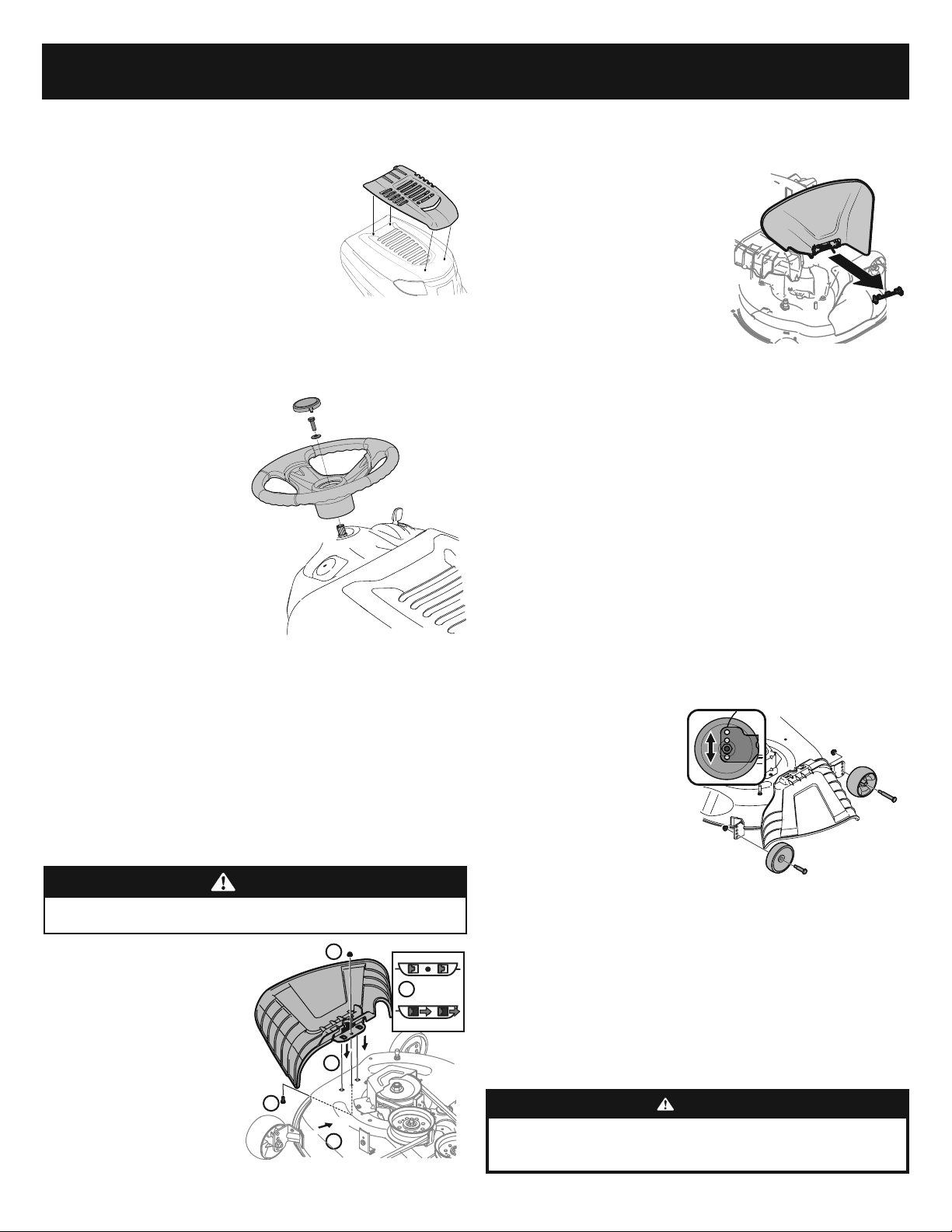
Attaching the Hood Topper (If Necessary/If Equipped)
Note: Be careful not to damage the headlight harness when installing the hood topper.
1. Cut the cable ties securing the hood topper to the
tractor.
2. Remove the four screws pre-installed in the hood
topper and retain for Step 4.
3. Snap the hood topper into place using the hood as
your guide. See Figure 9.
4. Install the hood topper onto the hood of the tractor
and secure from the underside using the four screws
removed in Step 2.
Installing the Steering Wheel (If necessary)
The hardware for attaching the steering wheel has been packed within the steering
wheel, beneath the steering wheel cap.
Carefully pry off the steering wheel cap
and remove the hardware.
IMPORTANT! Do not use impact tools
to install or remove the steering wheel.
Doing so can overtorque and damage the
fastener.
1. Remove the key, attached with a
cable tie to the steering wheel.
2. With the front wheels of the tractor
pointing straight forward, align
the steering wheel (a) and place
it onto the steering shaft (b). See
Figure 10.
3. Secure the steering wheel (a) with the hex bolt (c) and washer (f) from under the
steering wheel cap (e) and torque to 18-22 ft.-lbs (24.4-29.8 N-m).
4. Place the steering wheel cap (e) over the center of the steering wheel (a) and
push downward until it “clicks” into place.
NOTE: The hex bolt (c) securing the steering wheel (a) has thread locker applied
to it, so if it is removed, it is recommended that the hex bolt (c) be replaced or
thread lock re-applied.
Lower Deck Discharge Chute Deflector (If Equipped)
WARNING
Never operate the mower deck without the chute deflector installed and in the
down position.
46” Deck Models
1. Remove the key attached with a
zip tie to the chute bracket.
2. Remove the flange lock nut and
hex screw from the deck.
3. Place the chute deflector on the
deck, be sure to insert the tabs on
the chute deflector into the holes
on the deck. See Figure 11.
4. Slide the chute deflector toward
the rear of the tractor until the
bolt hole in the chute deflector
aligns with the hole in the deck.
See Figure 11.
5. Secure the chute deflector in place with the flange lock nut and hex screw
removed in step two. Tighten to 102-124 in-lbs (11.5-14 N-m). See Figure 11. Skip
ahead to “Setting the Deck Wheels”
42”/50”/54” Deck Models
1. Check the tractor deck for a shipping
brace that may be holding the chute
deflector upward for shipment. If the
shipping brace is present, it must be
removed before operating the tractor.
Holding the chute deflector fully upward,
remove the shipping brace.
2. Lower the chute deflector and discard
the shipping brace. See Figure 12.
Note: 36” deck models come equipped with mulch plugs rather than chute deflectors
and no shipping brace is included.
Setting the Deck Wheels (If Equipped)
NOTE: The deck wheels are an anti-scalp feature of the deck and are not designed to
support the weight of the cutting deck.
1. Move the tractor to a level surface, preferably pavement.
2. Check the tire pressure, adjust, if necesarry. See tire sidewall for proper tire
pressure.
3. Make sure the deck is level side-to-side and properly pitched. See the Maintenance
and Adjustments section for deck leveling information and instructions.
4. Place deck lift lever in the desired mowing height position.
5. Check the wheels for contact or excessive clearance with the surface below.
Note: The deck wheels should have between ¼”-½” (6.35-12.7mm) clearance
above the ground. Proceed as follows to adjust the wheels:
a. Raise the deck lift lever
to its highest setting.
b. Remove the front
(a) and rear (b) deck
wheels by removing
the flange lock nuts (c)
and shoulder bolts (d)
that secure them to the
deck. See Figure 13.
c. Place the deck lift lever
in the desired mowing
height setting.
d. Reinsert the shoulder bolt (with each deck wheel) into the index hole
that leaves approximately ½” (13mm) between the bottom of the wheel
and the pavement. Tighten the flange lock nut and shoulder bolt to
between 25-30 ft-lbs (34-40 N-m) using a torque wrench.
NOTE: Refer to Adjusting the Deck in the Service and Maintenance section of this
manual for more detailed instructions regarding various deck adjustments.
Battery Information
WARNING
California PROPOSITION 65 WARNING: Battery posts, terminals, and
related accessories contain lead and lead compounds, chemicals known to the State
of California to cause cancer and reproductive harm. Wash hands after handling.
Figure 9
(b)
(a)
(c)
(d)
(e)
Figure 10
3
4
5
5
4
Figure 11
Figure 12
(a)
(b)
(c)
(d)
(d)
(c)
Figure 13
Loading ...
Loading ...
Loading ...