Loading ...
Loading ...
Loading ...
12
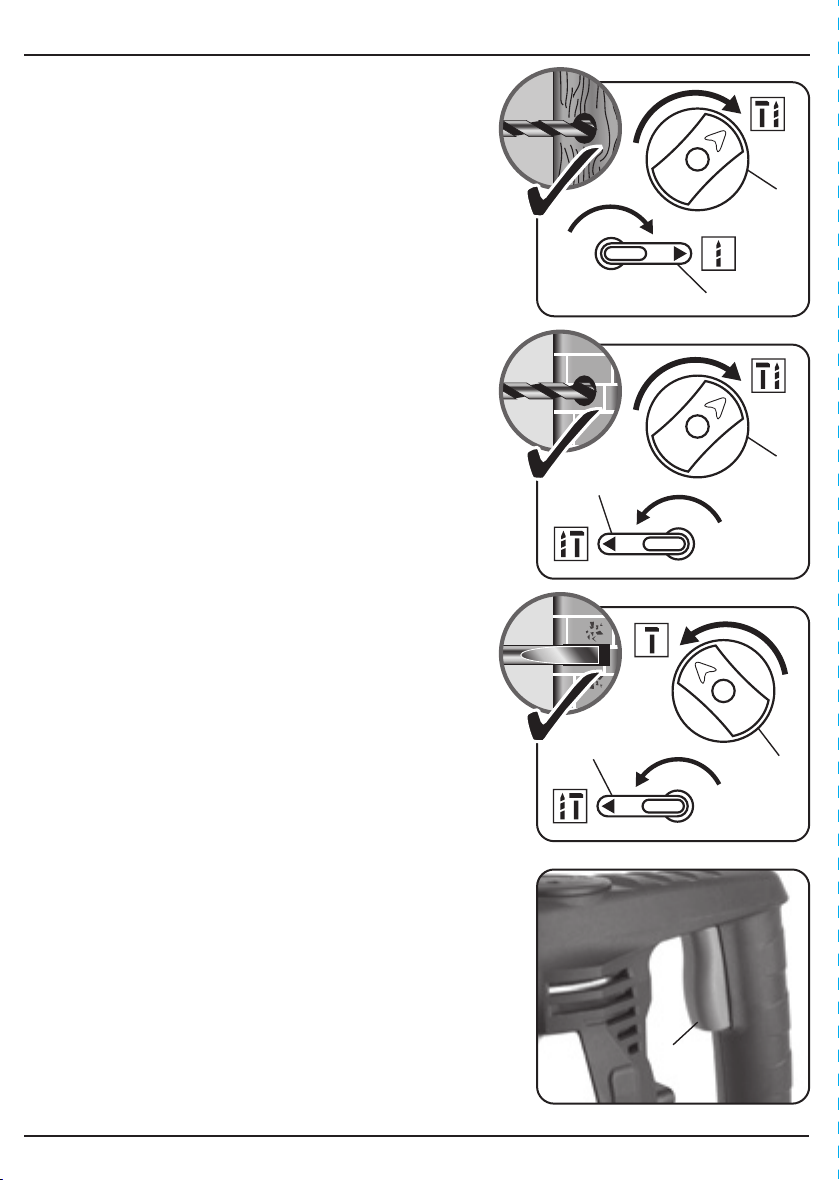
9.2 ROTARY DRILLING – FIG. 6
With the drill at standstill:
– Position the rotary/ hammer selection dial to
the right.
– Move the rotation/stop lever to the right.
This set-up is for standard drilling ie. into wood/metal.
9.3 PNEUMATIC HAMMER DRILLING – FIG. 7
With the drill at standstill:
– Position the rotary/ hammer selection dial to
the right.
– Move the rotation/stop lever to the left.
This set-up is for masonry drilling ie. into brick,
concrete, block work, etc.
9.4 PNEUMATIC CHISELLING – FIG. 8
With the drill at standstill:
– Position the rotary/ hammer selection dial to
the left.
– Move the rotation/stop lever to the left.
This set-up is for chiselling with the chuck rotation stop
engaged ie. chiselling/chasing out brickwork,
plasterboard, etc.
9.5 TRIGGER SWITCH – FIG. 9
Select the required function.
– Pull trigger to activate the machine.
9. BASIC HAMMER DRILL OPERATIONS
FIG.6
FIG.9
FIG.7
FIG.8
Loading ...
Loading ...
Loading ...