Loading ...
Loading ...
Loading ...
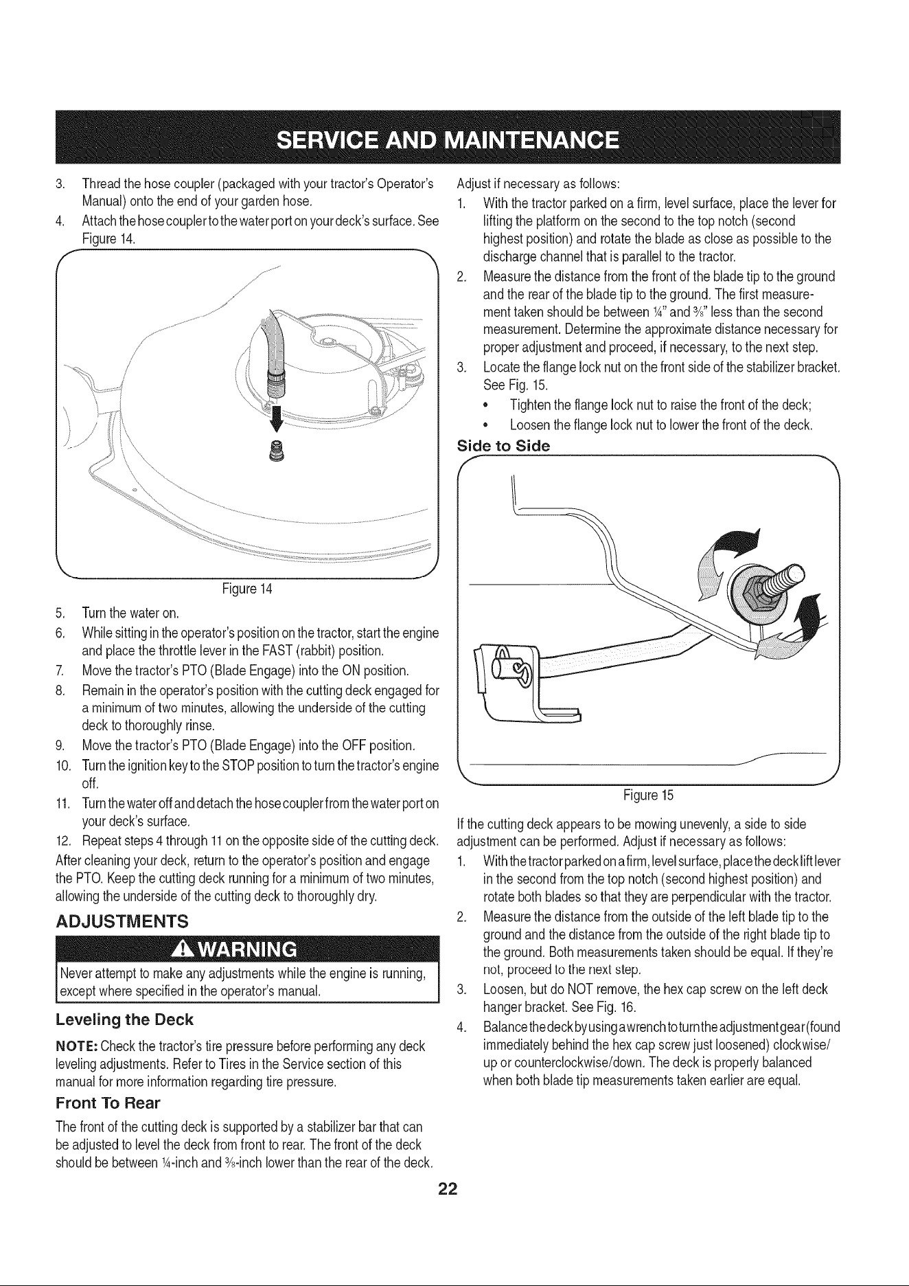
3. Threadthe hosecoupler(packagedwith yourtractor'sOperator's
Manual)ontothe endof your gardenhose.
4. Attachthehosecouplertothewaterporton yourdeck'ssurface.See
Figure14.
J
j,
/
f
J _; .......... ........
8
Figure14
5. Turnthe wateron.
6. Whilesittingintheoperator'spositiononthe tractor,starttheengine
andplacethe throttleleverinthe FAST(rabbit)position.
7. Movethe tractor'sPTO(BladeEngage)intothe ON position.
8. Remainin theoperator'spositionwiththecuttingdeck engagedfor
a minimumof two minutes,allowingthe undersideof the cutting
deckto thoroughlyrinse.
9. Movethe tractor'sPTO(BladeEngage)intothe OFFposition.
10. Turntheignitionkeytothe STOPpositionto turnthetractor'sengine
off.
11. Turnthewateroffanddetachthehosecouplerfromthewaterporton
yourdeck'ssurface.
12. Repeatsteps4 through11on the oppositesideof the cuttingdeck.
Aftercleaningyourdeck, returnto the operator'spositionand engage
the PTO.Keepthe cuttingdeckrunningfor a minimumof twominutes,
allowingthe undersideof thecuttingdeckto thoroughlydry.
ADJUSTMENTS
Neverattemptto makeanyadjustmentswhilethe engineis running,
exceptwherespecifiedin the operator'smanual.
Leveling the Deck
NOTE: Checkthe tractor'stire pressurebeforeperforminganydeck
levelingadjustments.Referto Tiresinthe Servicesectionof this
manualfor moreinformationregardingtire pressure.
Front To Rear
Thefrontof the cuttingdeckissupportedby a stabilizerbarthatcan
beadjustedto levelthe deckfromfront to rear.Thefront of the deck
shouldbebetween_A-inchand 3A-inchlowerthan the rear of thedeck.
Adjustif necessaryas follows:
1. Withthe tractorparkedona firm, levelsurface,placethe leverfor
liftingthe platformon the secondto the top notch(second
highestposition)and rotatethe bladeas closeas possibleto the
dischargechannelthatis parallelto the tractor.
2. Measurethedistancefromthe frontof the bladetip to the ground
andthe rearof the bladetip to theground.Thefirst measure-
menttakenshouldbe between_A"and3A"less thanthe second
measurement.Determinethe approximatedistancenecessaryfor
properadjustmentand proceed,if necessary,to the nextstep.
3. Locatethe flangelocknuton thefront sideof thestabilizerbracket.
See Fig.15.
• Tightenthe flangelocknut to raisethe frontof the deck;
• Loosentheflangelock nutto lowerthe frontof thedeck.
Side to Side
Figure15
f__
J
Ifthe cuttingdeckappearsto be mowingunevenly,a sideto side
adjustmentcan beperformed.Adjustif necessaryas follows:
1. Withthetractorparkedonafirm,levelsurface,placethedeckliftlever
in the secondfromthetop notch(secondhighestposition)and
rotatebothbladessothattheyare perpendicularwith the tractor.
2. Measurethedistancefromthe outsideof the left bladetip to the
groundandthe distancefrom the outsideof the rightblade tip to
the ground.Bothmeasurementstakenshouldbe equal.Ifthey're
not, proceedto the nextstep.
3. Loosen,but do NOTremove,the hexcap screwon the leftdeck
hangerbracket.SeeFig. 16.
4. Balancethedeckbyusingawrenchtoturntheadjustmentgear(found
immediatelybehindthe hexcap screwjust loosened)clockwise/
up orcounterclockwise/down.Thedeck is properlybalanced
when bothbladetip measurementstakenearlierareequal.
22
Loading ...
Loading ...
Loading ...