Installation Instructions
Heritage Pro Range
HDPR30S, HDPR36S, HDPR48S, HDER30S, HDER36S, HDER48S
Part No. 113428 Rev A

2 English
Table of Contents
Before You Begin 3
Important Notes 3
Customer-Assurance Information 3
Important Safety Instructions 4
Safety Symbols and Cautionary Information 4
Installation-Related Safety Instructions 5
Consignes de sécurité importante 7
Instructions de sécurité relatives à l'installation 7
Product Specications 9
HDPR30S, -36S, -48S Ranges 9
HDER30S, -36S, -48S Ranges 10
Included Accessories: HDPR30S/HDER30S 11
Included Accessories: HDPR36S, -48S/HDER36S, -48S 12
Needed Parts and Tools 13
Installation Requirements 14
Pre-installation Checklist 14
General Requirements 15
Location Requirements 17
Gas Requirements 18
Electrical Requirements 19
Installation Instructions 20
Preparing for Installation 20
Making the Electrical Connection 24
Making the Gas Connection 29
Final Installation 30
Verifying Proper Operation 33
Moving the Range for Service 34
Installation Checklist 34
3English
Before You Begin
Important Notes
Installer
• Read this manual thoroughly before installing the cooktop.
• Remove all packaging before connecting the electric and gas supplies.
• Observe all governing codes and ordinances.
• Leave this manual with the owner, and write the unit’s model/serial numbers inside for reference.
• Installation of the range requires basic mechanical skills.
Owner
• As with any heat-generating appliance, certain precautions must be followed.
•
not warrantied.)
• Ensure the wall coverings near the range can withstand the heat it generates.
• Keep this manual handy for personal and professional reference.
Service Technician
The wiring diagram is in an envelope attached to the inside of the rangetop.
Dacor Customer Assurance
Phone:
Hours of Operation:
Website: www.dacor.com/customer-care/contact-us
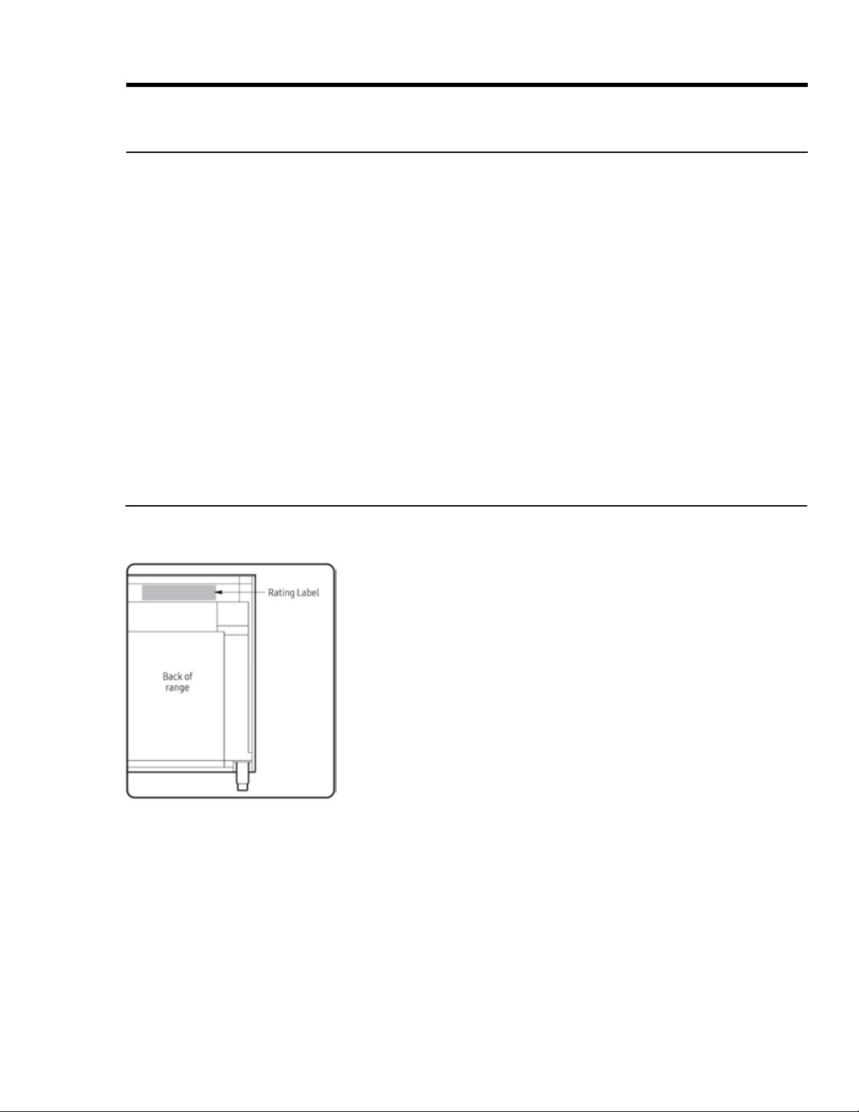
Model Identication
•
•
•
•
•
•
Customer-Assurance Information
calling, have ready the range’s model/serial numbers, which are on the rating label on the back of the range..
4 English
Safety Symbols and Cautionary Information
Electrical and gas equipment can be dangerous if not handled properly. The Important Safety Instructions in
the instructions in this manual.
Important Safety Instructions
About the Symbols In This Manual
These icons alert you to potentially unsafe conditions or helpful information.
Hazards or unsafe practices that may result in severe personal injury or death.
Hazards or unsafe practices that may result in electric shock, personal injury, or property damage.
About the Anti-tip Bracket
All ranges can tip and cause personal injury and death. Install and check the anti-tip bracket as instructed.
• Installing the Anti-Tip Bracket
carefully tipping the range forward. The bracket should keep the range safely in place.
• When the range is put back in place after maintenance, be sure it engages the anti-tip bracket.
• To avoid personal/property damage, do not step/sit/lean on the range.
State of California Proposition 65 Warning (USA only)
•
reproductive harm.
• -
Commonwealth of Massachusetts
•
• If using ball-type gas shut-off valves, you must use the T-handle type.
•

5English
Important Safety Instructions
Installation-Related Safety Instructions
•
and to ensure proper installation.
• These safety instructions cover installation-related safety issues. For use-and-care-related safety instruc-
Installation-Specic Safety
• Remove all tape and packing material.
•
•
• The range should be moved by two or more people.
• After unpacking the range, remove all accessories, taking care with heavy pieces.
• Verify that no parts came loose or were damaged during shipping.
•
-
tions and local regulations. The installer shall ensure proper conversion.
•
-
Appliance-Location Safety
• Install the range indoors away from weather/water/strong drafts.
• If the range is near a window, do not hang paper blinds or curtains that could be blown over/onto the range.
•
•
•
•
•

6 English
Important Safety Instructions
Installation-Related Safety Instructions, cont.
to ensure proper installation.
Gas Safety
• close the range's gas-supply valve and evacuate the building
•
• do not turn on any gas or electric appliances
• do not plug in a power cord or touch an electrical switch
• do not use any phone in your building
•
Checking For Gas Leaks
-
tion. If there is a gas leak, small bubbles will appear in the solution. If unsure, call for professional help.
Fire Safety
•
•
•
• Regularly clean the oven vents.
• Do not use a towel or other bulky cloth as a pot holder.
•
•
• Do not heat sealed containers.
Electrical and Grounding Safety
• Do not use a damaged plug, cord, or loose power outlet, and do not alter the plug, cord, or outlet.
• Do not put a fuse in a neutral or ground circuit.
•
into this circuit.
• If unsure that the intended outlet is properly grounded, have a licensed electrician check it.
•
not connect the ground wire to plastic plumbing/gas lines, or hot-water pipes.
•
• The owner shall ensure the range receives the proper electrical service.

7English
Consignes de sécurité importantes
Instructions de sécurité relatives à l'installation
• Lisez attentivement ces instructions pour réduire les risques de dommages matériels, d'incendie, de bless-
ures corporelles et de mort, et pour assurer une installation correcte.
•
de cuisson et le four, se reporter au manuel de l'utilisateur.
Sécurité spécique à l'installation
• Enlever tout le ruban et le matériel d'emballage.
•
•
•
•
•
•
-
•
-
édition.
Sécurité de l'emplacement de l'appareil
•
•
•
•
• -
isolant similaire.
•
les vapeurs.
•
armoires.

8 English
Consignes de sécurité importantes
Instructions de sécurité relatives à l'installation, suite
Lisez attentivement ces instructions pour réduire les risques de dommages matériels, d'incendie, de blessures
corporelles et de mort, et pour assurer une installation correcte.
Sécurité du gaz
•
•
arc plus léger)
•
• ne branchez pas un cordon d'alimentation ou ne touchez pas un interrupteur électrique
• n'utilisez aucun téléphone dans votre immeuble
•
Vérication des fuites de gaz
de doute, appelez une aide professionnelle.
La sécurité incendie
•
•
•
•
•
•
usage multiple.
•
•
Sécurité électrique et de mise à la terre
•
ou la prise.
•
•
•
•
•
•
9English
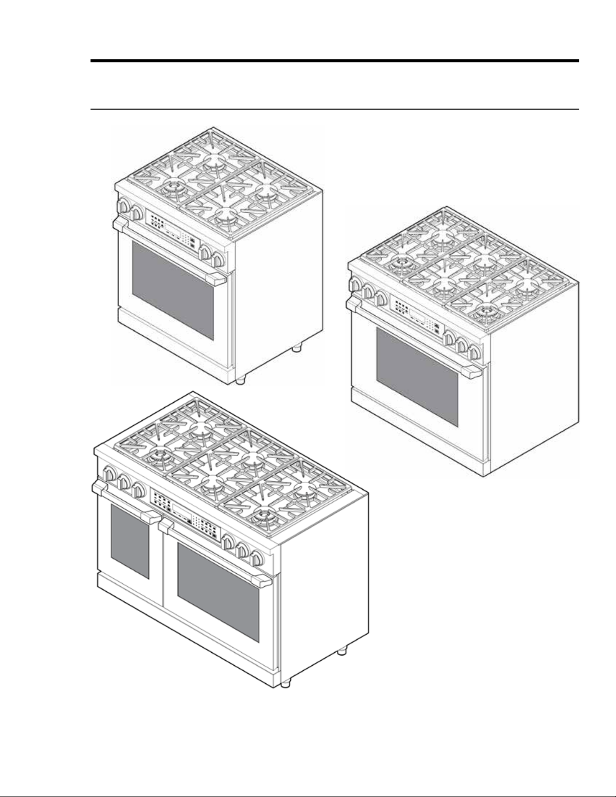
Product Specications
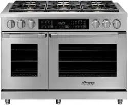
HDPR30S, -36S, -48S Ranges
HDPR48S
HDPR36S
HDPR30S
10 English
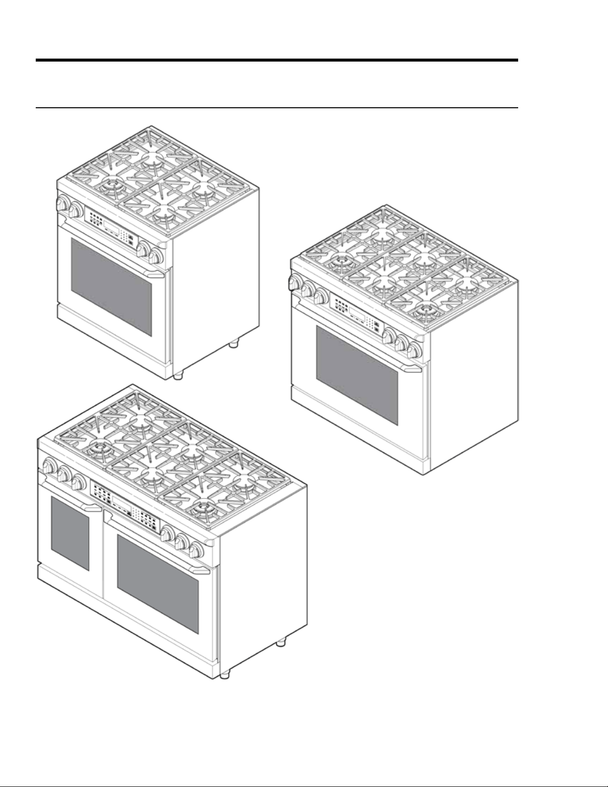
Product Specications
HDER30S, -36S, -48S Ranges
HDER48S
HDER36S
HDER30S
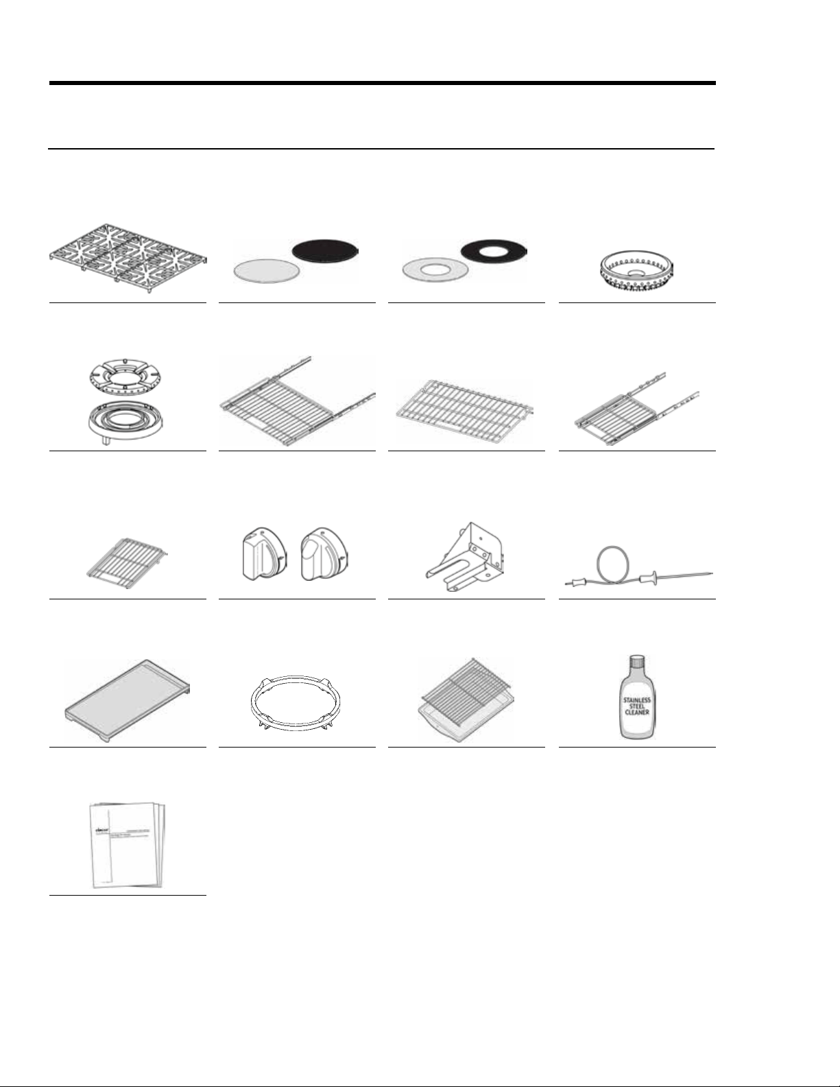
11English
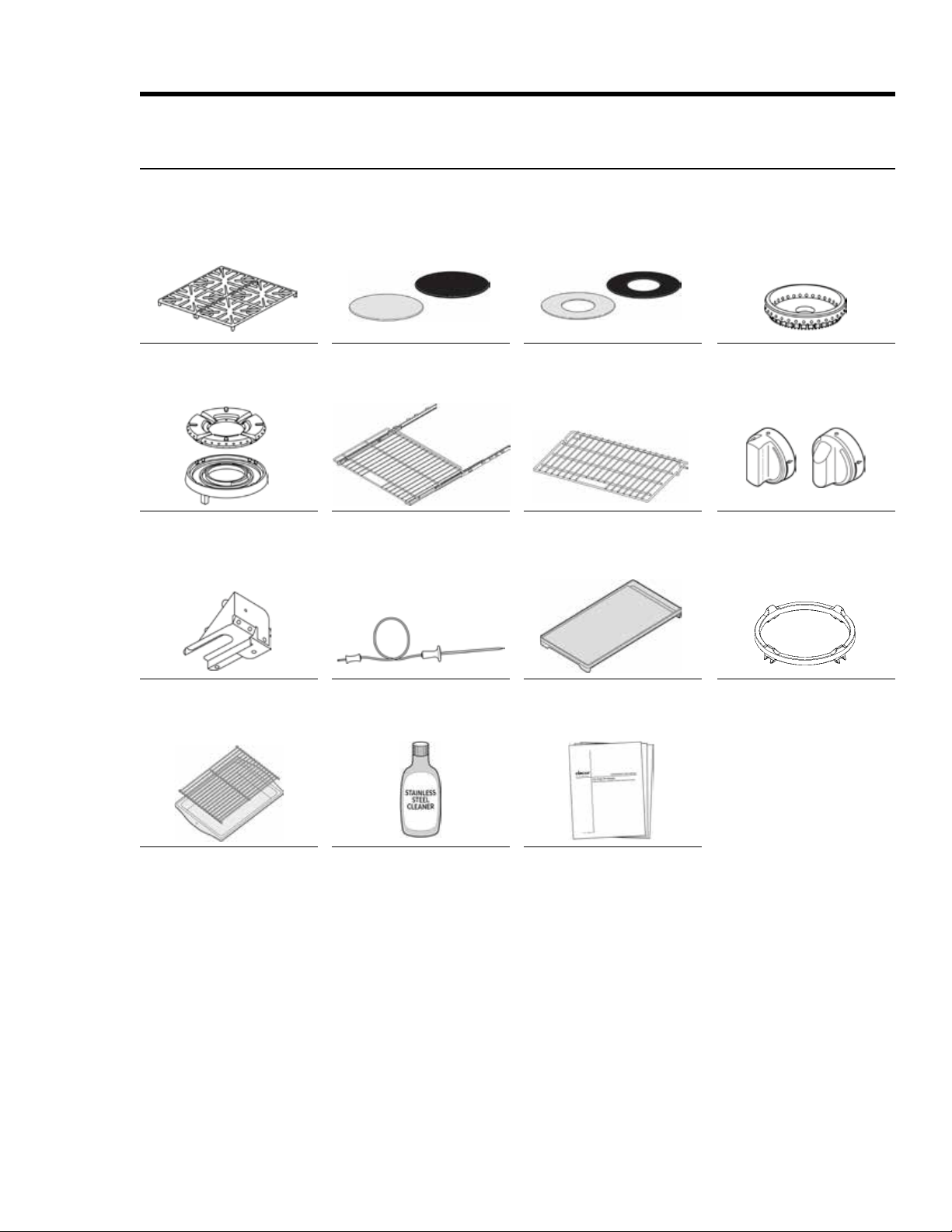
and Anchors
TM
Literature Kit
Product Specications
Included Accessories: HDPR30S/HDER30S
12 English
Literature Kit
TM
and Anchors
TM
Product Specications
Included Accessories: HDPR36S, -48S/HDER36S, -48S
13English
Product Specications
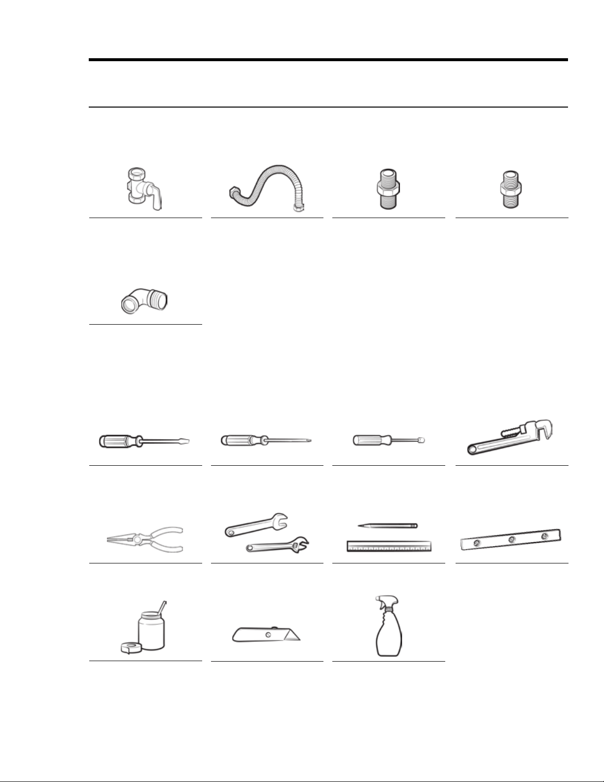
Needed Parts and Tools
Needed Parts
Open-End or Adjustable
Wrench
Level
Needed Tools
14 English
Installation Requirements
Pre-Installation Checklist
F
F
F
that all items are present before beginning the installation.
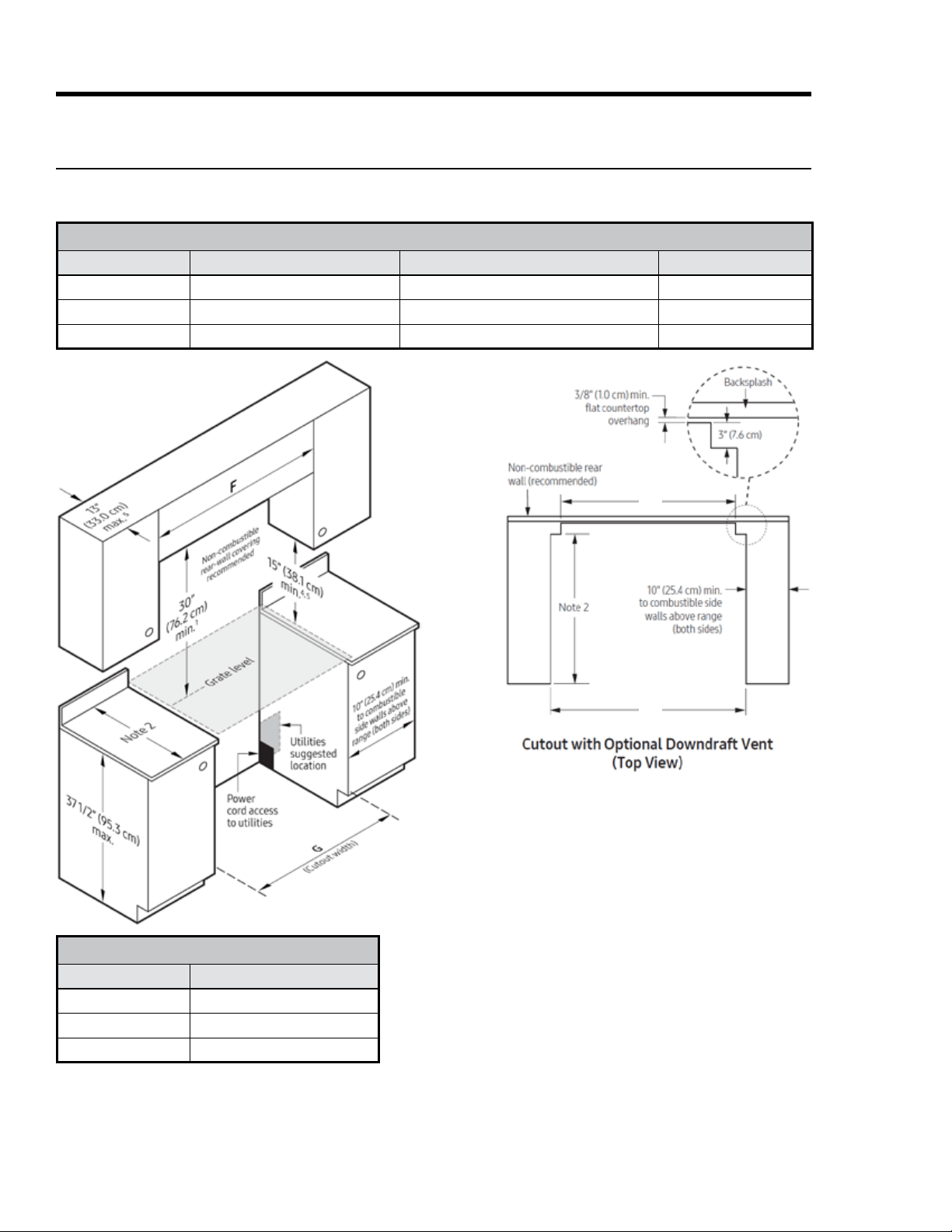
General Requirements
Clearances and Dimensions
• For OTR installations above a gas cooktop, follow the local gas code.
• For safe operation, provide adequate space between the range and combustible surfaces. Location of the
electrical outlet and gas piping may be adjusted to meet the dimensions and clearances in this manual.
• Either a backguard or non-combustible material must be installed on the wall between the range and
•
coverings, countertops, and cabinets must tolerate such heat to avoid discoloration/delamination/melting.
Minimum Dimensions
•
those cabinets.
•
•
• The hood must be at least as wide as the range and centered over it.
• -
ances, follow that appliance’s installation criteria.)
•
metal cabinet
or
•
15English
Installation Requirements
General Requirements, cont.
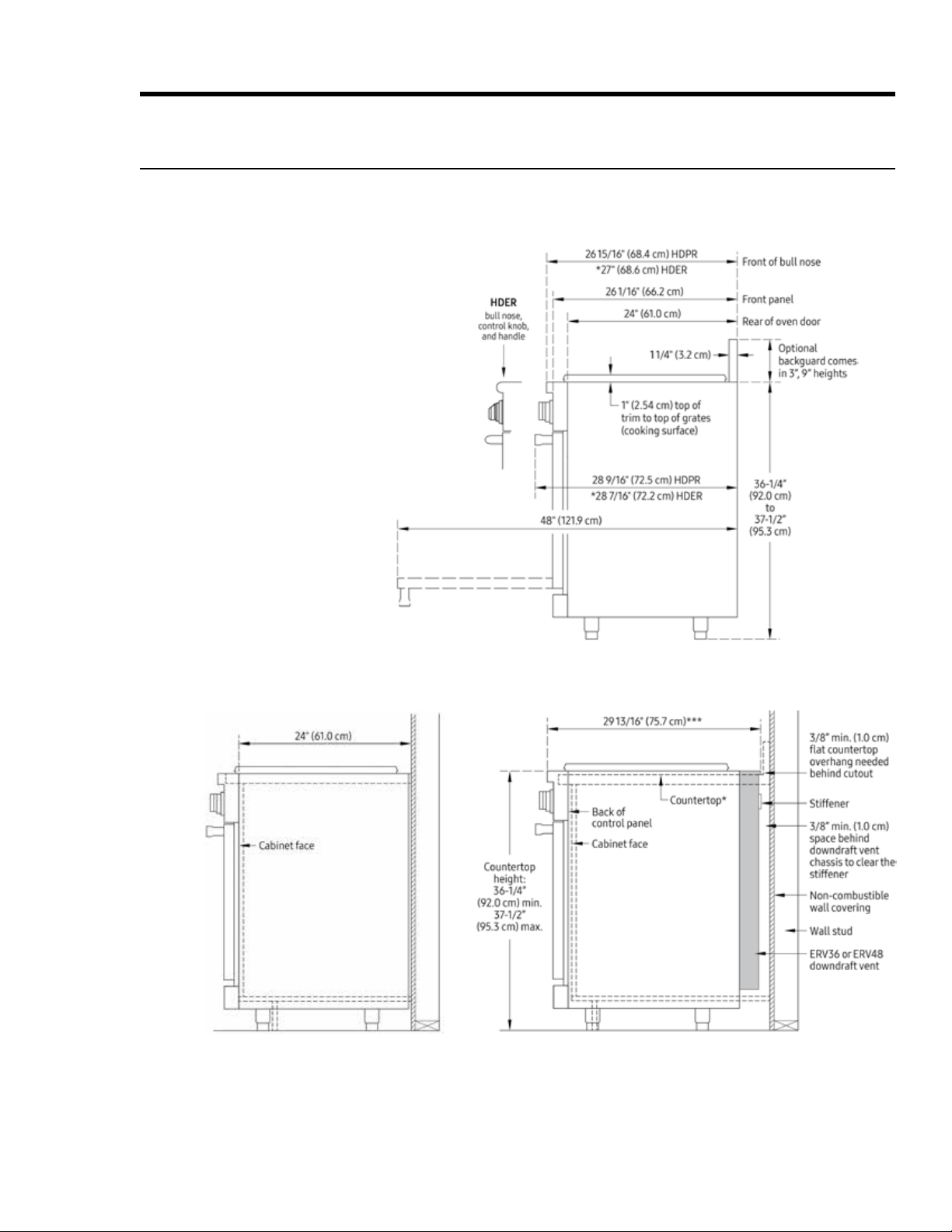
Product Dimensions (tolerances: ±1/16” ±1.6 mm)
HDPRS/HDERS30HDPRS/HDERS36HDPRS/HDERS48
Range-Only Installation Range-With-Downdraft Installation
Critical Depth/Height Dimensions
16 English
Installation Requirements
CUTOUT DIMENSIONS
Model F—recommended/min G—min/max H
General Requirements, cont.
Cabinet Dimensions
Standard Cutout with
Range Hood
Vertical from range grate level to combustible overhead
-
cations for minimum required clearances.
but cabinet face must not protrude beyond the rear of
Product Dimensions
3.
Vertical from grate level to combustible surface.
5.
APPROVED DOWNDRAFT VENT MODELS
Range Downdraft Vent
IMPORTANT:-
tions for duct and electrical installation requirements.
G
H
17English
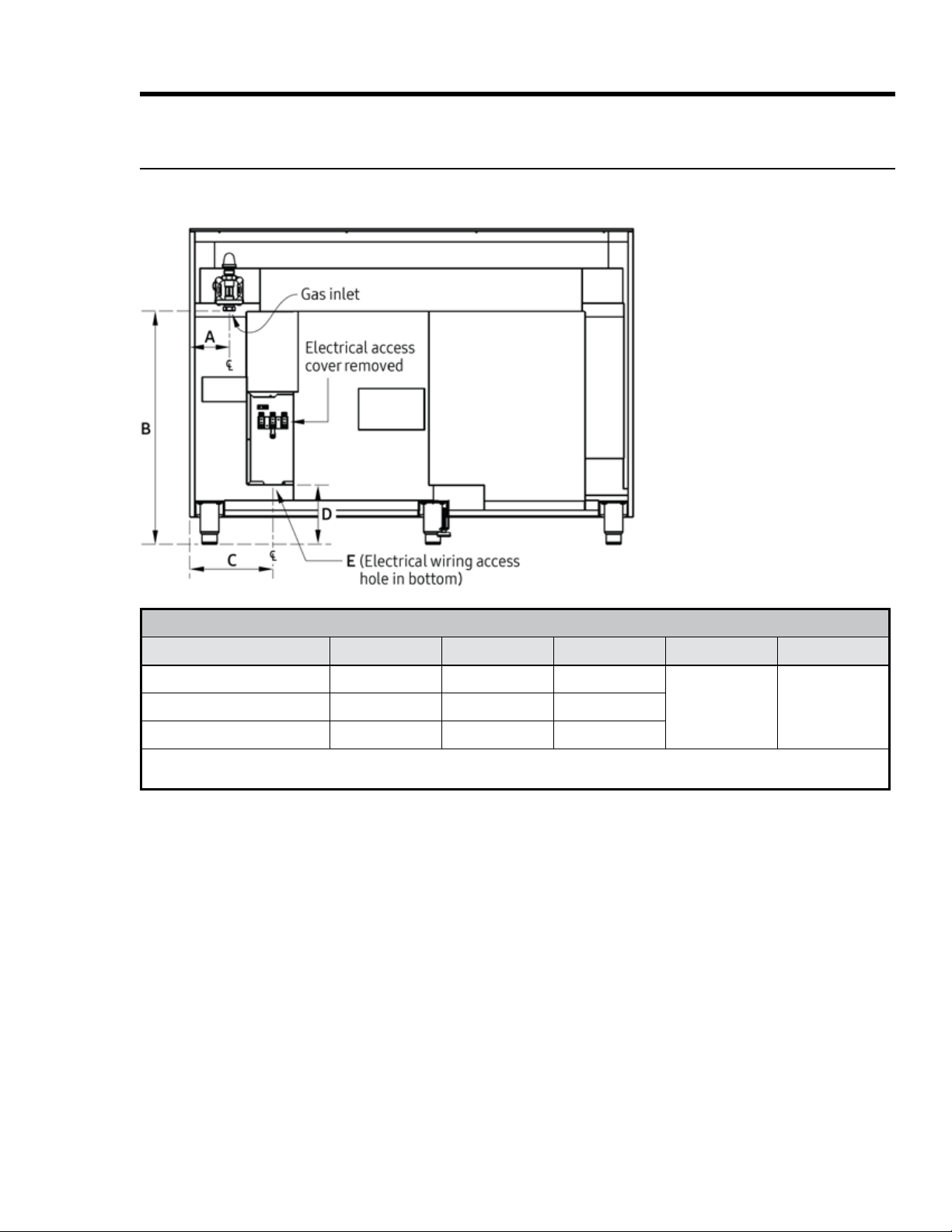
Installation Requirements
Location Requirements
Gas/Electrical Range Hookups (HDPRS/HDERS 30”, 36”, 48”)
Gas/Electrical Service Inlets
•
allowed gas-valve locations.)
•
on/off.
•
•
placement requirements for the range.
•
being disconnected.
GAS-/ELECTRICAL-ACCESS DIMENSIONS
Model A B* C D* E**
18 English
Gas Requirements
Provide Adequate Gas Supply
•
•
• Verify that the oven is right for the provided gas service. When verifying regulator function, inlet pressure
•
•
right are for reference only.
Installation Requirements
Special Gas Requirements (gas models sold in Massachusetts)
•
•
• A T-handle, manual gas valve must be installed in the gas-supply line to the range.
•
• The pressure regulator at
the inlet of the cooktop
manifold must stay in the supply line no matter the type of gas used.
•
shut-off valve.
•
•
•
MINIMUM GAS-SUPPLY PRESSURE REQUIREMENTS*
Gas Type Min. Manifold Pressure Min. Gas-Supply Pressure**
19English
Installation Requirements
Electrical Requirements
Follow these directions to reduce risk of property damage, personal injury, or death.
The owner shall ensure that the electrical service meets requirements and that the electrical outlet is properly
grounded and installed by a licensed electrician.
The correct voltage, frequency, and amperage must be supplied to the range from a separate, grounded,
• The wiring must be long that the range can be pulled out for service without being disconnected.
•
–
– include a strain relief
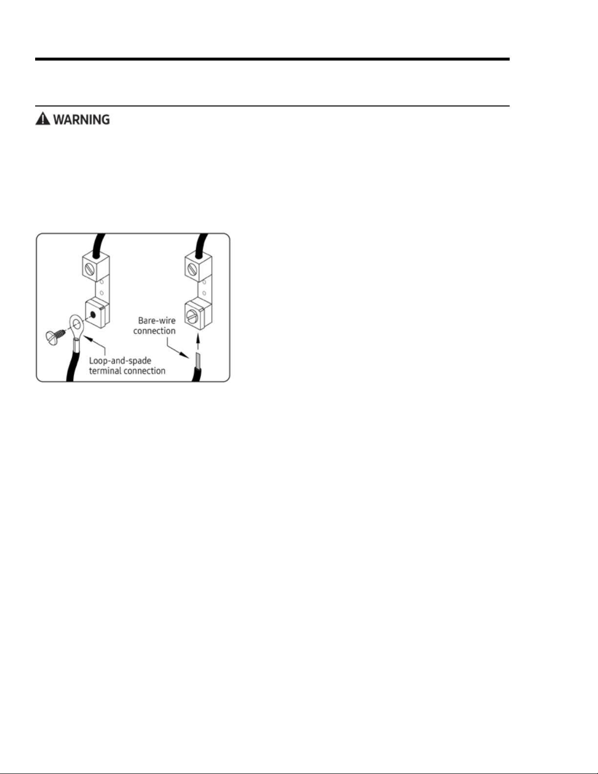
– be terminated by tinned leads, closed-loop terminals, or open-ended spade lugs with upturned ends
–
•
–
–
•
–
–
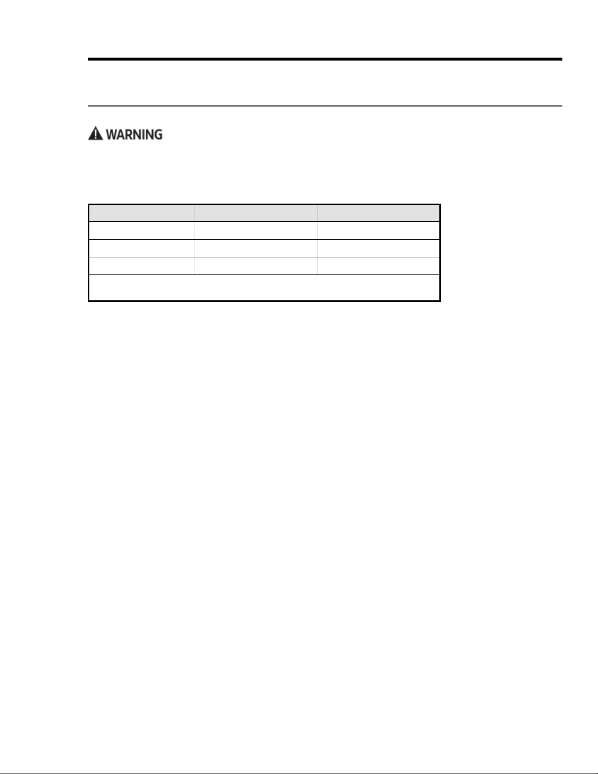
–
Model Required Circuit Total Connected Load
20 English
Installation Instructions
Preparing for Installation
•
and call the dealer, gas supplier, or a licensed electrician.
•
Unpacking the Range
-
ing or damaged, contact your dealer immediately. Do not install a damaged or incomplete range.
Installing a Backguard (optional)
Install the backguard before making the range gas and electrical connections. Install according to the back-
guard kit instructions.
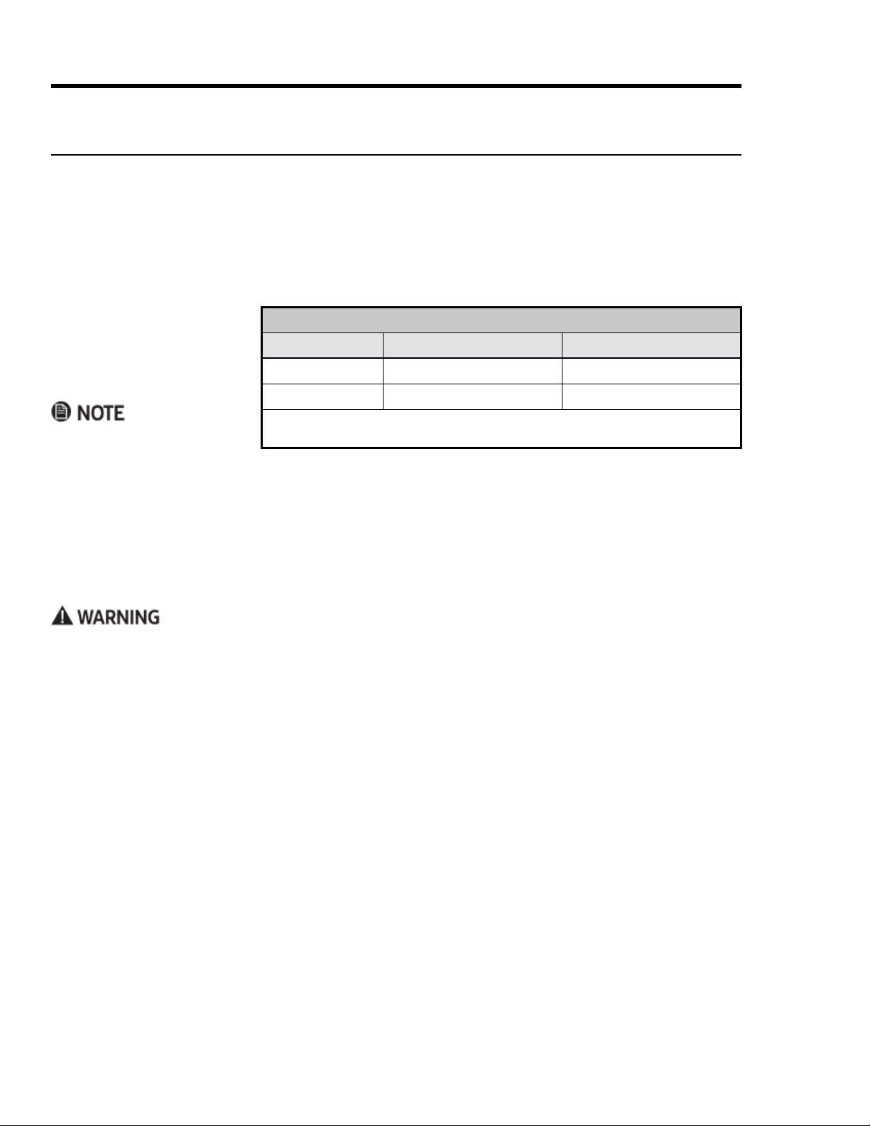
Approved Backguard Models Backguard Description For Range Model
Installing the Anti-tip Bracket and Foot
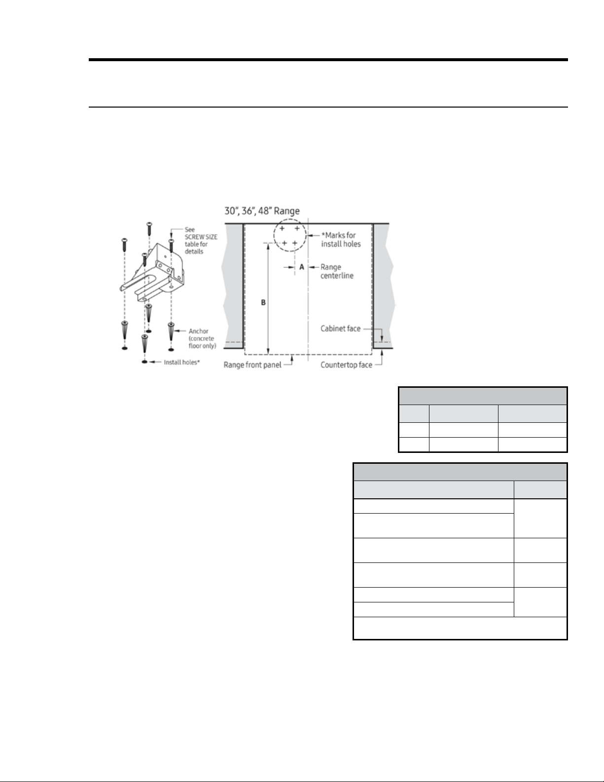
Floor-Mounting the Anti-tip Bracket
as ceramic/asphalt tile or linoleum.
•
• Determine the location of the range center line and front
Product Dimen-
sions
used for the installation.
21English
Preparing for Installation, cont.
Installing the Anti-tip Bracket and Foot, cont.
Floor-Mounting the Anti-tip Bracket, cont.
•
•
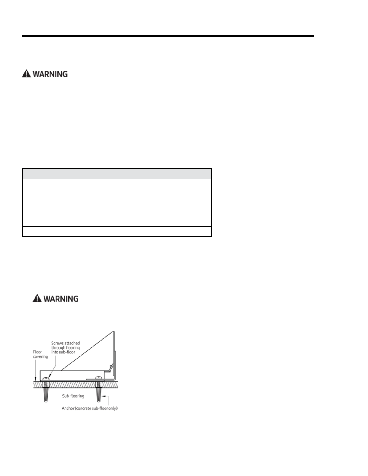
Attaching the Bracket to a Concrete Floor
bit. This hole length is longer than the anchor.
3.
Align the bracket and anchor holes, then insert
and tighten the screws.
Attaching the Bracket to a Wood Sub-Floor
drilling pilot holes.
holes, then insert and tighten the screws.
Installation Instructions
SCREW SIZE
Sub-oor Type/Floor Cover Thickness Screw Size
thick
ANTI-TIP BRACKET PLACEMENT
Dim.
30, 36 48
A
22 English
Installation Instructions
Preparing for Installation, cont.
Installing the Anti-tip Bracket and Foot, cont.
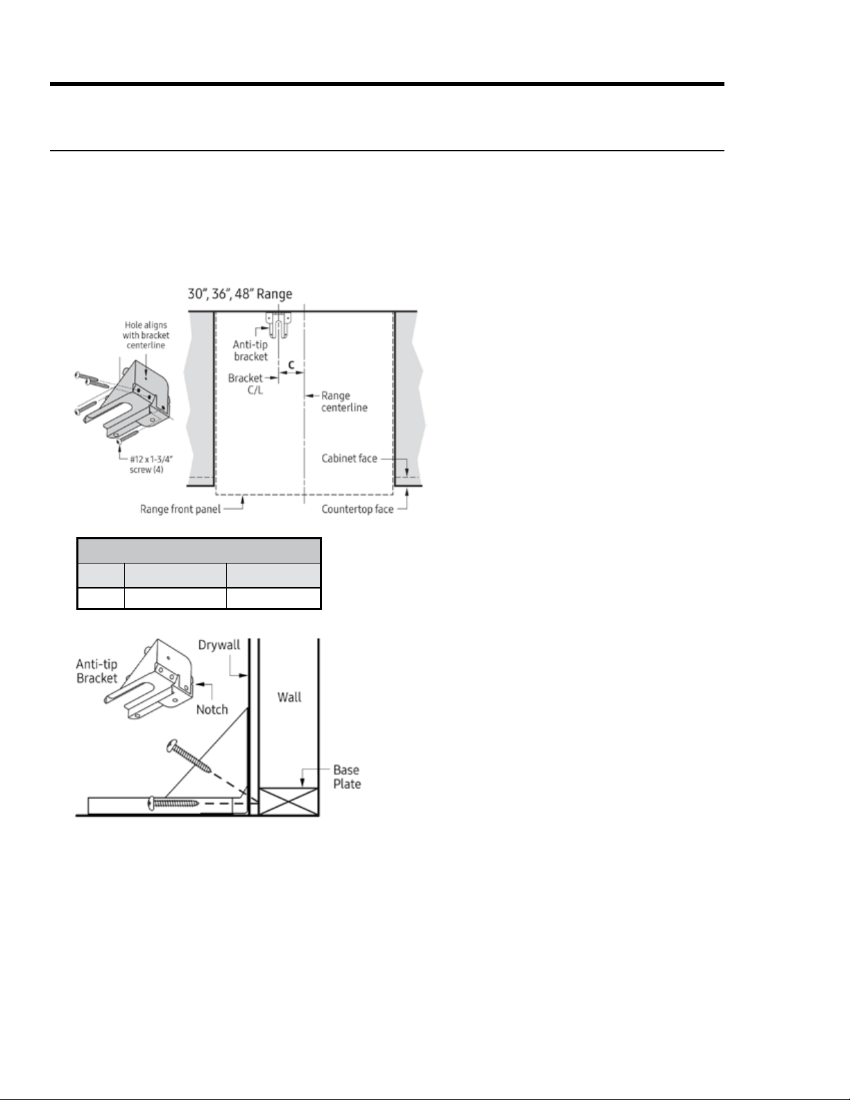
Wall-Mounting the Anti-tip Bracket
-
ness will not impede secure threading.
5. Having determined the wall-mounting is suitable, place the bracket against the wall in the mounting
location.
surfaces shown.
ANTI-TIP BRACKET PLACEMENT
Dim.
30, 36 48
cutout dimensions, determine the position of the range's
position.
against the wall.
3.
sides of the bracket.
Drill just deep enough to see if the bit contacts the base
plate. If there is contact, you can wall-mount the bracket.
If there is no contact, wall mounting is unsuitable, and
adding base material above the notches.
23English
Installation Instructions
Preparing for Installation, cont.
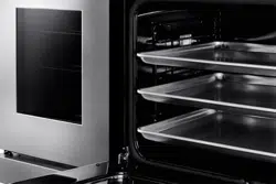
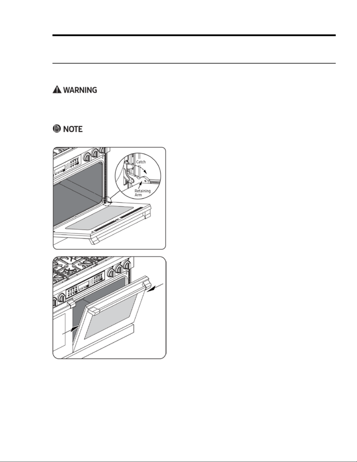
Removing the Oven Door
• -
ing personal injury.
•
which to put the oven door after you remove it.
Open the door fully.
3.
catch out over the retaining arm on each hinge.
5. With both hands, grasp the door just below the handle,
and pull the door away from the oven.
prepared.
24 English
Installation Instructions
Making the Electrical Connection
• Wire the range according to local ordinances.
• Improperly connected electrical wiring can lead to electric shock and appliance damage. Dacor is not re-
sponsible for damage due to improper electrical connection.
•
grounding conductor.
•
• Do not install a fuse in the neutral or ground circuit, which may cause electric shock.
IMPORTANT
• Do not disconnect wires inside the range’s electrical ac-
cess cover unless instructed to do so.
•
range can be pulled out for service without disconnecting it.
• -
ing the electrical connections.
• -
–
– 3-wire conduit
–
– 3-wire power cord
•
supply wire only if local building codes permit.
•
connection methods.
25English
Installation Instructions
Making the Electrical Connection, cont.
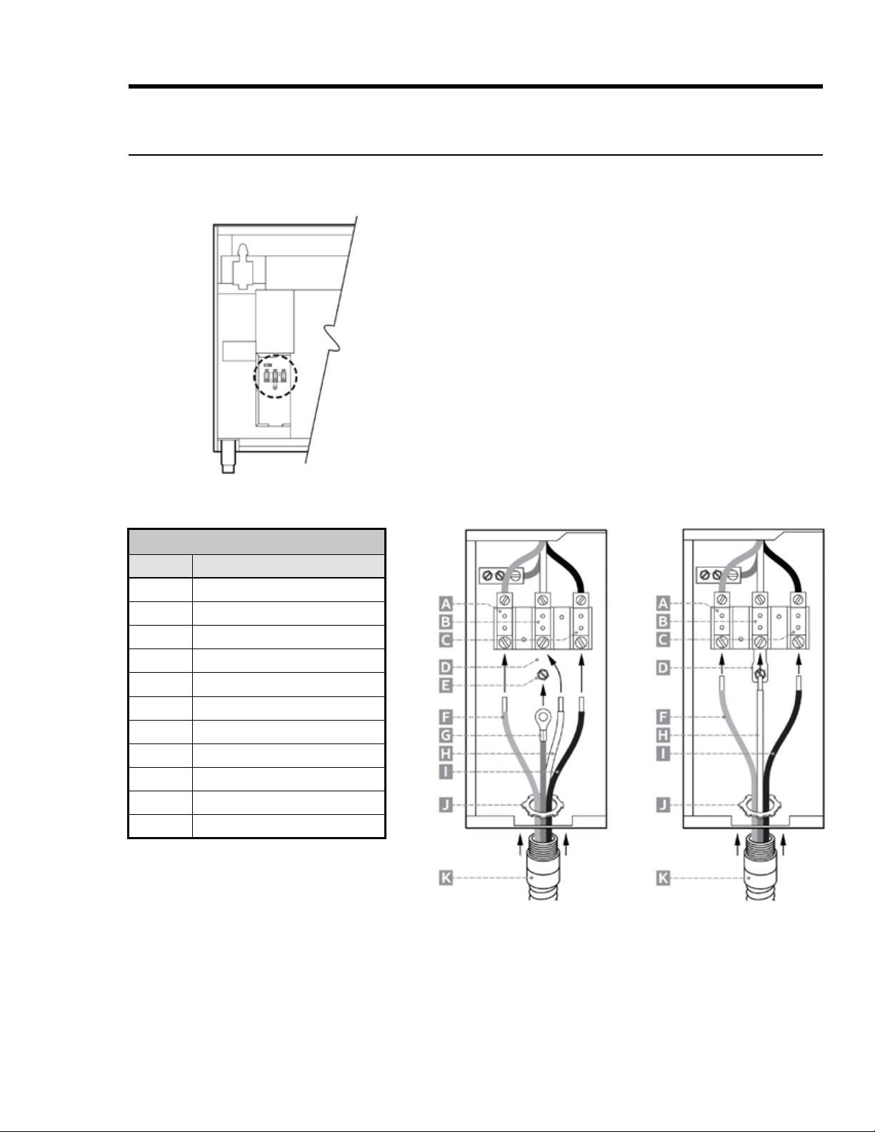
Connecting the Conduit to the Range
CONDUIT-TO-RANGE CONNECTIONS
Callout Description
A
D
E
F
Red wire
H
White wire
I
K
2. (4-wire only)-
3.
5.
over the wires, then thread and tighten it onto the strain
8.
9. (4-wire only)-
Re-attach the electrical-access cover.
3-Wire Connection
(if local code allows)
4-Wire Connection
26 English
Installation Instructions
Making the Electrical Connection, cont.
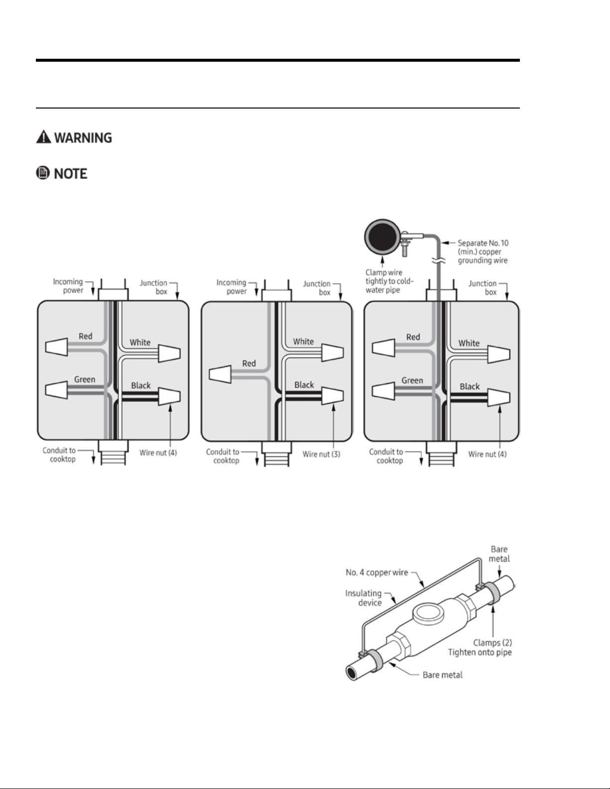
Connecting the Conduit to the House’s Junction Box
• The power supply must be properly polarized so the burner igniters do not keep sparking after ignition.
• If you are unsure the power supply is properly polarized/grounded, have it checked by a licensed electrician.
With the range in front of the cabinet cutout, feed the conduit wires
3.
5. (4-wire only)
-
–
connector screw.
– If materials isolate the cold-water pipe from ground, jumper
4-Wire Conduit Connection to
Junction Box
3-Wire Conduit Connection to
Junction Box
4-Wire Conduit Connection to
Junction Box w/External Ground
27English
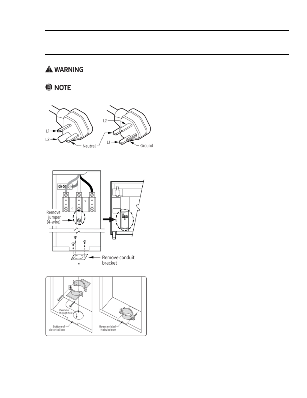
Remove the range’s electrical-access cover.
2. (4-wire only) Loosen the ground screw, and remove the
neutral-to-ground jumper link.
3.
Remove the strain relief from the power cord.
a. Insert the tabs on each part of the strain relief down
b. Reassemble the strain relief so the tabs are under the
Installation Instructions
Making the Electrical Connection, cont.
Connecting a Power Cord to the Range
10-50P 3-Prong Plug (left); 14-50P 4-Prong Plug (right)

28 English
Installation Instructions
Making the Electrical Connection, cont.
Connecting a Power Cord to the Range, cont.
POWER-CORD CONNECTIONS
Callout Description
A
D
E
F
H
White wire
I
4-Wire Cord Connection
5. Insert the end of the cord up through the hole/
strain relief.
a. -
b.
c.
d. (4-wire only)
8. Re-attach the electrical-access cover.
3-Wire Cord Connection
(if local code allows)
29English
Installation Instructions
Making the Gas Connection
•
•
•
•
•
• -
• The range must be isolated from the gas-supply piping by closing the shut-off valve during any pressure
•
-
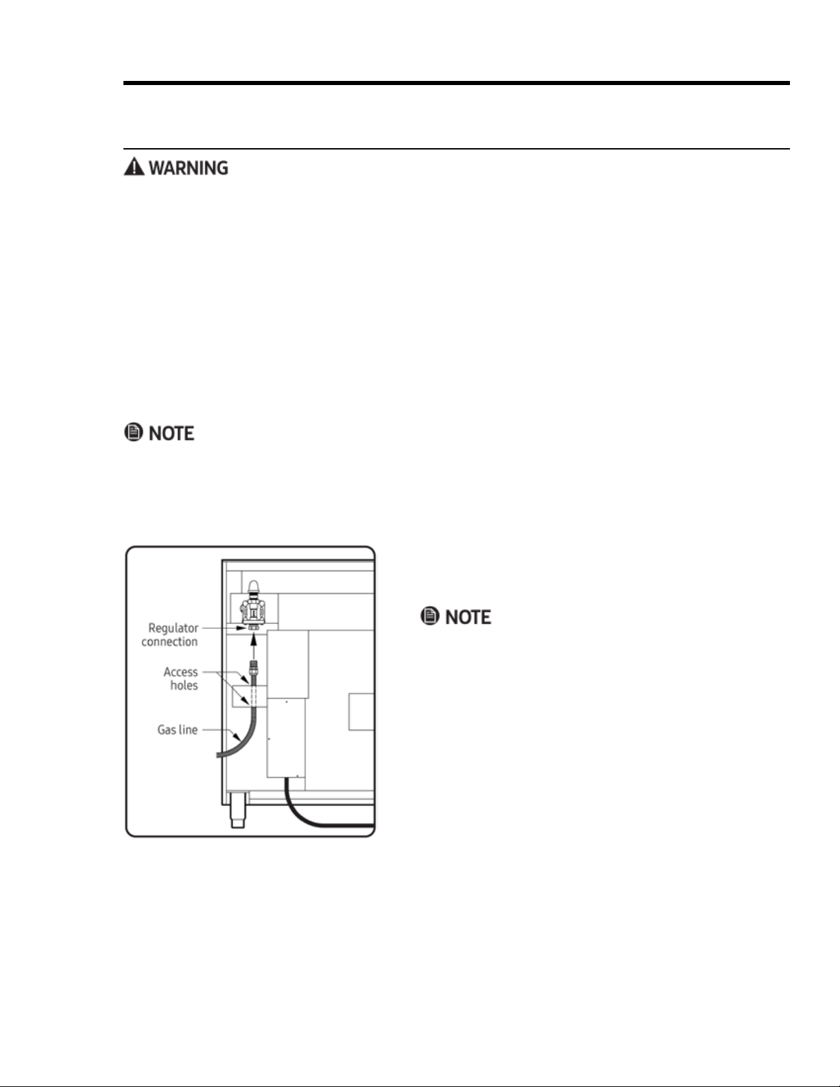
Before Sliding the Range Into the Cutout
valve on the stub out.
The line must be long enough that the range can be pulled
out for service without disconnecting the line.)
3.
access holes so the gas line can pass smoothly upward.)
5. With all cooktop controls off, open the gas-supply valve.
connections for leaks.
-
ply valve connected to the range.
30 English
Installation Instructions
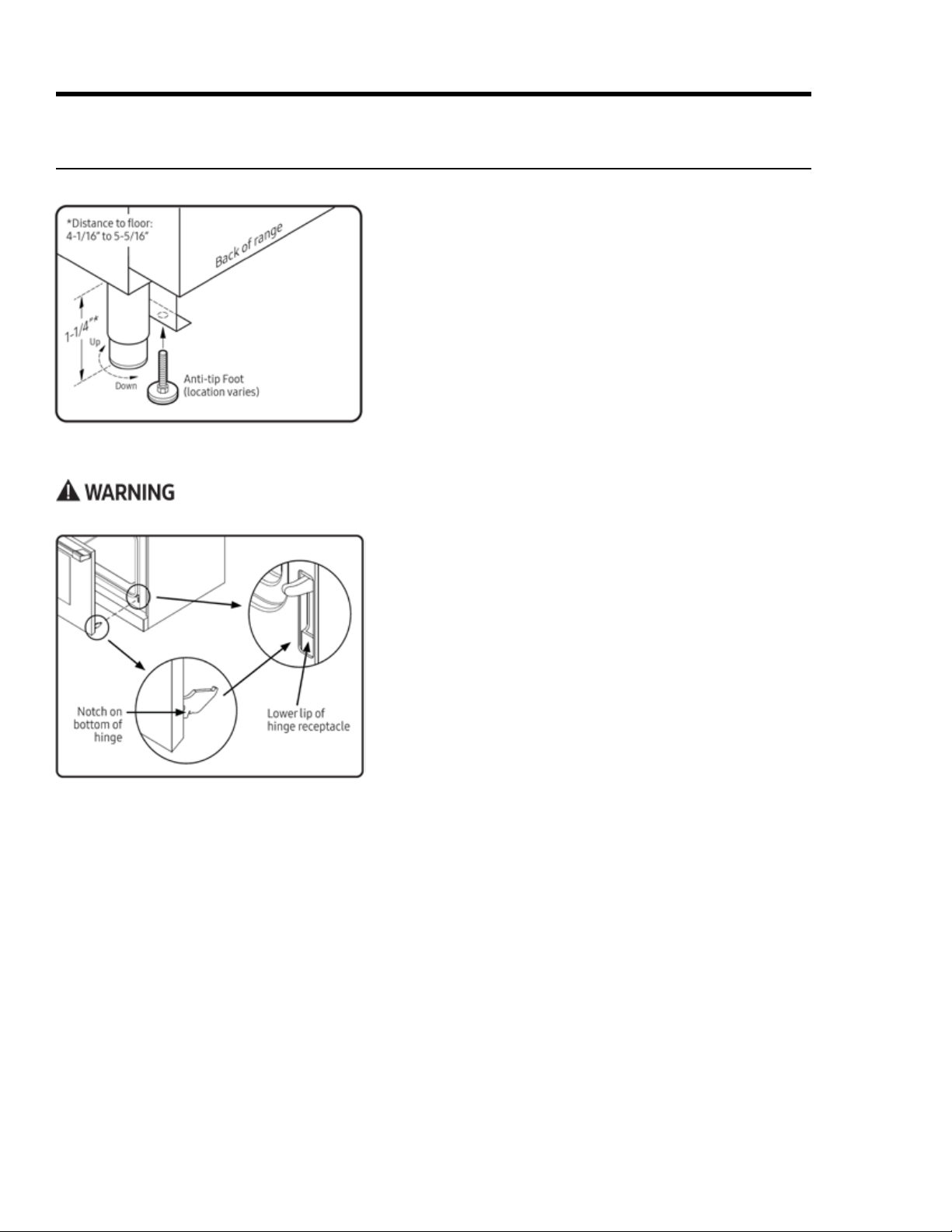
Attaching the Oven Door(s)
countertop.
3.
5.
the anti-tip bracket.
With a level, check that the range does not tilt in any
their receptacles.
3. -
tom corners until the notch on the bottom of each hinge
slips over the lower lip of each hinge receptacle.
Fully open the door.
5. Flip the two hinge locks toward the oven.
it is properly installed.
Final Installation
Installing the Anti-tip Foot
31English
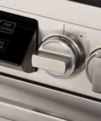
Assembling Cooktop Components
Installation Instructions
Match the D-shaped opening on the back of each knob
with the D-shaped valve shaft of the appropriate burner,
push the knob fully onto the shaft.
a.
b.
Final Installation, cont.
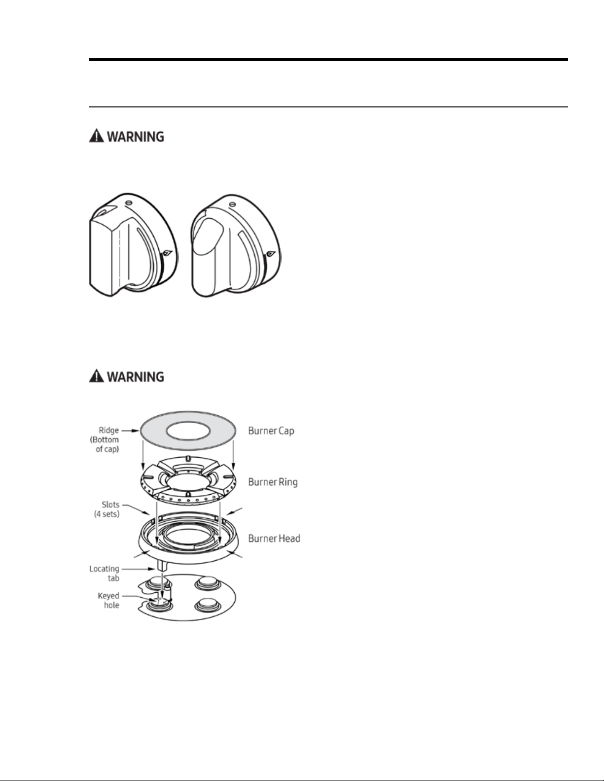
Installing the Burner-Control Knobs
Pro Knob for
HDPRS Models
Epicure Knob for
HDERS Models
Do not operate the cooktop unless all burner components are properly assembled.
Installing SimmerSear Burner Components
Install the burner head so the burner head’s locating
tab is in the burner base’s keyed hole.
3.
slots in the head.
Install the burner cap so the ridge on the bottom of
32 English
Installation Instructions
Final Installation, cont.
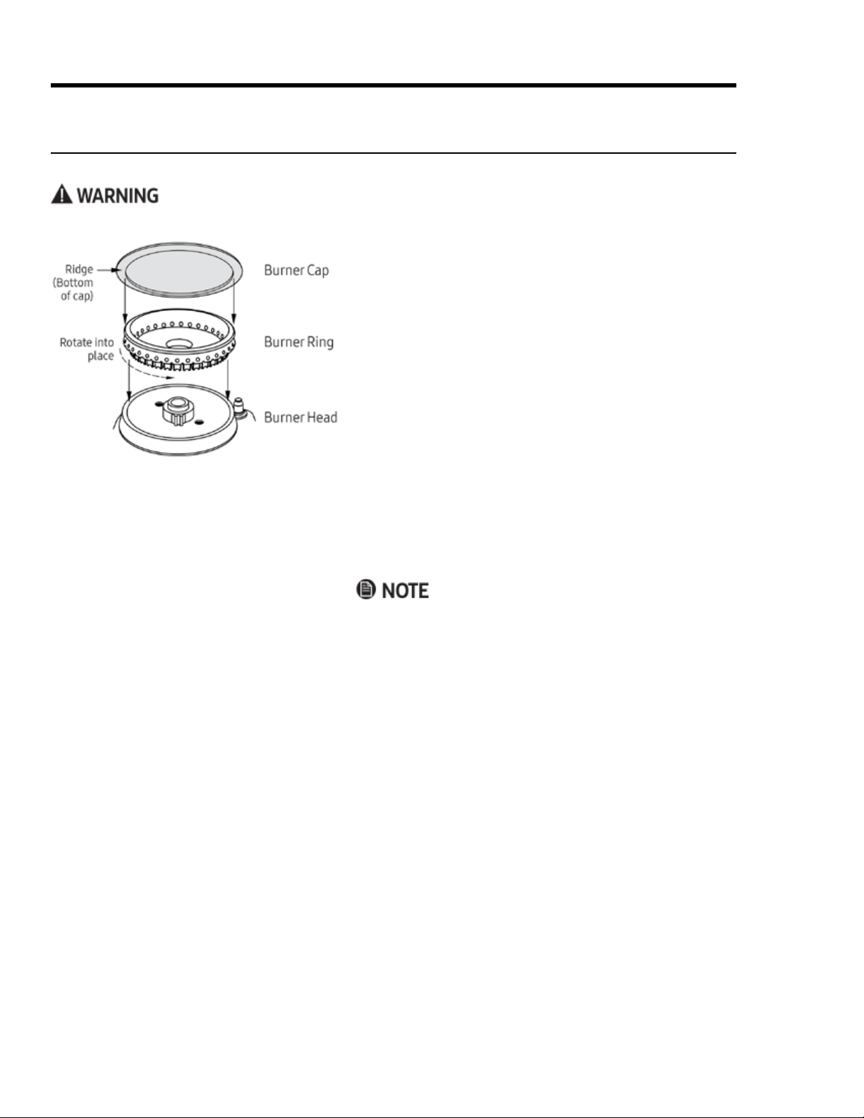
Assembling Cooktop Components, cont.
Do not operate the cooktop unless all burner components are properly assembled.
Installing Standard Burner Components
around the burner head, and rotate the ring until it drops
into place.
3. Install the burner cap so the ridge on the bottom of the
Installing the Grates
formed into the cooktop.
The grates are identical and may be placed over any pair of
burners front-to-back.
33English
Installation Instructions
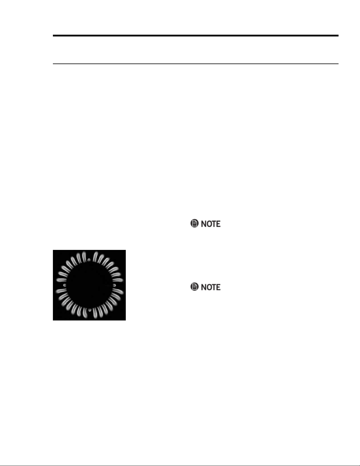
Verifying Proper Operation
service, and warranty information.
Turn off all burners, and verify that all burner compo-
nents are properly assembled.
Open the gas-supply valve, and verify that there are no
gas leaks.
3. Turn on power to the range at the power source.
Follow the prompts on the oven display to establish user
preferences and wireless-network settings.
5.
The default bake temperature appears on the display.
Open the door to verify that the oven is heating.
8.
The oven's heating elements turns off.
5 minutes for gas to dissipate, then try again.
inner cone that varies in length with the burner size.
Turn off the burner, and run the test for the other burners.
Proper
Flame

34 English
Installation Instructions
Moving the Range For Service
3.
5.
Open the gas-supply valve.
Installation Checklist
Installer
Owner
-
cian. Dacor is not responsible for property damage or product failure due to improper installation of the range.
F
F
F
F
F
F
F
F
F
F
F
F

35English
Notes

Dacor – 14425 Clark Avenue, City of Industry, CA 91745 – Phone (800) 793-0093 – Fax (626) 403-3130 – www.dacor.com