Page 1
GAS-FIRED
Owner’s Manual For Models:
Q3X-3
Q3XN-3
B102188-0-0114Page 2
IMPORTANT
This manual should be read thoroughly by the person installing the grill and all persons
who will use and maintain the grill. The installer should be sure the manual is left in the
possession of the user. The user should retain this manual for future reference when us-
ing or cleaning the grill and to properly identify any repair parts that may be required.
WARNING
Reference this manual for proper installation and maintenance instructions. Improper
installation, adjustment, alteration, service or maintenance can cause personal injury or
property damage. For assistance or additional information consult a qualied installer,
service agency or the gas supplier.
DANGER: FOR YOUR SAFETY
IF YOU SMELL GAS:
1. Shut off gas to the grill.
2. Extinguish any open ame.
3. Open the grill lid.
4. If odor continues, keep away from the appliance and imme-
diately call your gas supplier or your re department.
WARNING: FOR YOUR SAFETY
1. Do not store or use gasoline or other ammable vapors or liquids in the vicinity of
this or any other appliance.
2. An LP cylinder not connected for use shall not be stored in the vicinity of this or any
other appliance.
CAUTION:
Parts may have sharp edges. Wear leather work gloves and handle parts carefully dur-
ing the unpacking, assembly and installation.
WARNING
Broilmaster Gas Grills must ONLY use propane cylinders equipped with an Overll Pro-
tection Device (OPD). Use only a reputable propane dealer when exchanging or lling
cylinders. An overlled or improperly lled propane cylinder can be dangerous.

B102188-0-0114 Page 3
Congratulations!
Welcome to the beauty, durability, and prestige of a Premium Gas Grill
by Broilmaster. With award-winning excellence built into every feature
and durability that surpasses other Premium gas grills, Broilmaster has
manufactured the ultimate gas grill for discriminating outdoor chefs for
over 30 years.
At Broilmaster, we continually strive to enhance the performance and
quality of our products for your grilling enjoyment. Every effort will be
made to ensure that Broilmaster continues to be your choice as the
Premium grill of the future.
Whether you are at the lake or in the privacy of your own backyard, the
Broilmaster Premium Gas Grill performs far beyond the ordinary and is
designed to provide your family with years of outdoor cooking pleasure.
Thank You!
Broilmaster is a registered trademark of
Empire Comfort Systems, Inc.
918 Freeburg Ave.
Belleville, Illinois 62220
Telephone 800-851-3153
B102188-0-0114Page 4
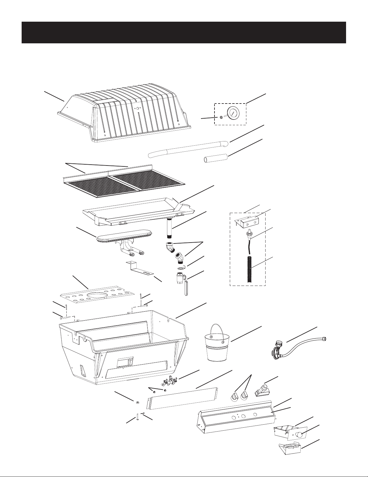
Order repair parts through your local Broilmaster
dealer. To locate a dealer in your area visit www.broil-
master.com. Please provide the following information when placing a repair part order: Model Number,
Purchase Date, Serial Number, Part Name, Part Number, and Quantity of parts needed. See Page 7
for parts ordering information.
PARTS DIAGRAM
1
4
5
6
7
8
9
10
11
12
15
16
16
17
18
19
20 or 21
22
23
24
25
26
13 or 14
17
27
29
31
28
30
16
37
36
34
35
32
33
3
2

B102188-0-0114 Page 5
PARTS LIST
INDEX
NUMBER
PART NUMBER DESCRIPTION
Q3X Q3XN
1 B101883 B101883 GRILL BODY TOP
2 B101665 B101665 PUSH NUT, 5/32”
3 DPP119 DPP119 HEAT INDICATOR
4 B070486 B070486 LID HANDLE
5 B073097 B073097 FOAM GRIP
6 B101732 B101732 COOKING SCREEN (2 PIECES, STAINLESS STEEL)
7 B101718 B101718 DRIP PAN (STAINLESS)
8 B101747 B101747 5.5” NIPPLE (DRIP TRAY DRAIN PIPE)
9 B101769 B101769 45° STREET EL (2 PCS., DRIP TRAY DRAIN)
10 B101780 B101780 BUCKET HOOK
11 B101778 B101778 DRAIN PIPE SHUT OFF VALVE
12 DPP113 DPP113 BURNER ASSEMBLY
13 P315 - ORIFICE, #60
14 - P208 ORIFICE, 1.45mm
15 B101742 B101742 CONTROL PANEL SHIELD
16 B057805 B057805 BRIDGE PIN
17 B057804 B057804 HINGE PIN
18 B101880 B101880 GRILL BODY BOTTOM
19 B101779 B101779 BUCKET
20 B101420 - VALVE - LP
21 - B101421 VALVE - NAT
22 B101622 B101622 SHIELD, CONTROL PANEL
23 B070084 B070084 VALVE KNOB
24 B072218 B072218 ELECTRONIC IGNITOR
25 B100743 B100743 CONTROL PANEL ASSEMBLY
26 B101724 B101724 SMOKER BOX
27 B101781 B101781 DRAWER SUPPORT
28 B101757 B101757 BURNER BRACKET
29 B076331 B076331 NUT, BURNER BRACKET
30 B101649 B101649 MACHINE SCREW, BURNER BRACKET
31 B069756 - HOSE AND REGULATOR
32 DPP117 DPP117 COLLECTOR BOX ASSEMBLY
33 B101833 B101833 ELECTRODE BRACKET
34 B101666 B101666 ELECTRODE
35 B102041 B102041 PROTECTIVE SLEEVE
36 B101517 B101517 CONTROL PANEL LABEL
38 B062998 B062998 SMOKER KNOB
NS B072684 B072684 IGNITOR GROUND WIRE
NS B102153 B102153 HARDWARE PACK
NS - Not Shown
B102188-0-0114Page 6
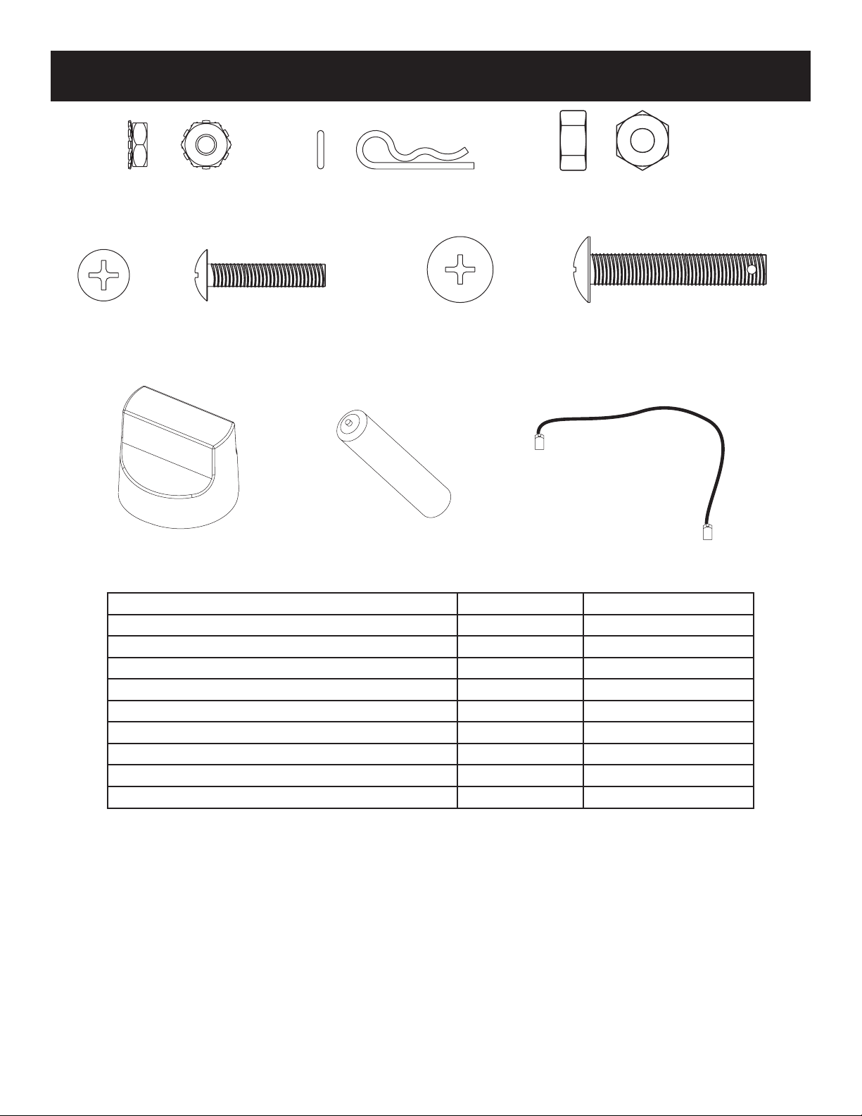
HARDWARE PACKAGE
10-24 KEPS NUT
PHILLIPS TRUSS HEAD SCREW 10-24 X
1
1/4-20 HEX NUT
PHILLIPS TRUSS HEAD SCREW 1/4-20 X 1 1/2
BRIDGE PIN
KNOB AA BATTERY WIRE, IGNITOR GROUND
DESCRIPTION PART NUMBER QUANTITY SUPPLIED
10-24 KEPS NUT B073967 2
PHILLIPS TRUSS HEAD SCREW 10-24 X 1 B073978 2
1/4-20 HEX NUT B076331 1
PHILLIPS TRUSS HEAD SCREW 1/4-20 X 1-1/2 B101649 1
BRIDGE PIN B057805 1
KNOB, VALVE B070084 2
WIRE, IGNITOR GROUND B072084 1
GRIP, FOAM (NOT SHOWN) B073097 1
BATTERY, AA B076529 1

B102188-0-0114 Page 7
To Order Parts Under Warranty, please contact your local Empire dealer. See the dealer locator at www.empirecomfort.
com. To provide warranty service, your dealer will need your name and address, purchase date and serial number, and the
nature of the problem with the unit.
To Order Parts After the Warranty Period, please contact your dealer or one of the Master Parts Distributors listed below.
This list changes from time to time. For the current list, please click on the Master Parts button at www.empirecomfort.com.
Please note: Master Parts Distributors are independent businesses that stock the most commonly ordered Original Equip-
ment repair parts for Heaters, Grills, and Fireplaces manufactured by Empire Comfort Systems Inc.
MASTER PARTS DISTRIBUTOR LIST
Parts Not Under Warranty
Parts can be ordered through your Service Person, Dealer, or a Master Parts Distributor. See this page for the Master Parts Distribu-
tors list. For best results, the service person or dealer should order parts through the distributor. Parts can be shipped directly to the
service person/dealer.
Warranty Parts
Warranty parts will need a proof of purchase and can be ordered by your Service Person or Dealer. Proof of purchase is required for
warranty parts.
All parts listed in the Parts List have a Part Number. When ordering parts, rst obtain the Model Number and Serial Number from the
name plate on your equipment. Then determine the Part Number (not the Index Number) and the Description of each part from the fol-
lowing illustration and part list. Be sure to give all this information . . .
Appliance Model Number Part Description
Appliance Serial Number Part Number
Type of Gas (Propane or Natural)
Do not order bolts, screws, washers or nuts. They are standard hardware items and can be purchased at any local hardware store.
Shipments contingent upon strikes, res and all causes beyond our control.
HOW TO ORDER REPAIR PARTS
Dey Distributing
1401 Willow Lake Boulevard
Vadnais Heights, MN 55101
Phone: 651-490-9191
Toll Free: 800-397-1339
Website: www.deydistributing.com
Parts: Heater, Hearth and Grills
Victor Division of F. W. Webb Company
200 Locust Street
Hartford, CT 06114
Phone: 860-722-2433
Toll Free: 800-243-9360
Fax: 860-293-0479
Toll Free Fax: 800-274-2004
Websites: www.fwwebb.com & www.victormfg.com
Parts: Heater, Hearth and Grills
East Coast Energy Products
10 East Route 36
West Long Branch, NJ 07764
Phone: 732-870-8809
Toll Free: 800-755-8809
Fax: 732-870-8811
Website: www.eastcoastenergy.com
Parts: Heater, Hearth and Grills
Able Distributors
2501 North Central Avenue
Chicago, IL 60639
Phone: 773-889-5555
Toll Free: 800-880-2253
Fax: 773-466-1118
Website: www. abledistributors.com
Parts: Heater

B102188-0-0114Page 8
WARRANTY TERMS
Empire Comfort Systems Inc. warranties this Broilmaster premium gas grill to be free from defects at the time of purchase and for the
periods specied below. Broilmaster Premium Gas Grills must be installed by a qualied technician and must be maintained and oper-
ated safely, in accordance with the instructions in the owner’s manual. This warranty applies to the original purchaser only and is not
transferable. All warranty repairs must be accomplished by a qualied gas appliance technician.
Limited Lifetime Parts Warranty – Against Rust-Through
If the items listed below fail because of defective workmanship or material, Empire will repair or replace at Empire’s option. The
limited lifetime warranty provides one-time replacement of a covered component.
• Aluminum Grill Housing (except paint)
• Stainless Steel Cooking Grids and Stainless Steel Griddles
• Select Stainless Steel Components – Cart, Mounting, Bowtie Burner, Side Burner (DPSBSS), Side Burner Housing, and
Warming Rack
• Stainless Steel Built-In Components – Built-In Kits for 3-Series Grill Heads, Door Kit, Tilt-Out LP Tank Door, and Vent Register
Kit
Limited Ten-Year Parts Warranty – Against Rust-Through
If the items listed below fail because of defective workmanship or material, Empire will repair or replace at Empire’s option.
• Stainless Steel Burners for H-Series, Q-Series, and R3B
• Drip Pan for Q-Series
• Side Burner (DPASBC), Side Burner Housing (BSA)
Limited Five-Year Parts Warranty – Against Rust-Through
If the items listed below fail because of defective workmanship or material, Empire will repair or replace at Empire’s option.
• Infrared Burners on R3 or R3B
• Flare Buster™ Ceramic Flavor Enhancers
• Painted Electro-Galvanized Steel Components
• Stainless Steel Smoker Shutter
Limited Two-Year Parts Warranty – Against Rust-Through
If the items listed below fail because of defective workmanship or material, Empire will repair or replace at Empire’s option.
• Porcelain Coated Steel Briquette Racks
• Chrome-Plated Warming Rack
• Stainless Steel Flavor Screen
• Stainless Steel Heat Shield
Limited One-Year Parts Warranty
If the items listed below fail because of defective workmanship or material, Empire will repair or replace at Empire’s option.
• Valves, knobs, ignitors, labels, hoses, ttings, grease cups, drip buckets, and all other parts and accessories – including those
made from stainless steel – unless specied above
• Paint on Aluminum Grill Head
Duties Of The Owner
The appliance must be installed by a qualied installer and operated in accordance with the instructions furnished with the appli-
ance.
A bill of sale, cancelled check, or payment record should be kept to verify purchase date and establish warranty period.
Ready access to the appliance for service.
What Is Not Covered
Damages that might result from the use, misuse, or improper installation or storage of this appliance.
Travel, diagnostic costs and freight charges on warranted parts to and from the factory.
Claims that do not involve defective workmanship or materials.
Unauthorized service or parts replacements.
Removal and reinstallation cost.
Inoperable due to improper or lack of maintenance.
The costs of a service call to diagnose a problem and labor for replacement or repairs.
How To Get Service
To make a claim under this warranty, please have your receipt available and contact your installing dealer. Provide the dealer
with the model number, serial number, type of gas, and purchase verication. The installing dealer is responsible for providing service
and will contact the factory to initiate any warranted parts replacements. Empire will make replacement parts available at the factory.
Shipping expenses are not covered.
If, after contacting your Empire dealer, service received has not been satisfactory, contact: Consumer Relations Department,
Empire Comfort Systems Inc., PO Box 529, Belleville, Illinois 62222, or send an e-mail to [email protected] with “Consumer
Relations” in the subject line.
Your Rights Under State Law
This warranty gives your specic legal rights, and you may also have other rights, which vary from state to state.
Broilmaster is a Division of Empire Comfort Systems, Inc.

B102188-0-0114 Page 9
Before You Begin
All Broilmaster grills require some assembly and installation. Follow
all instructions unless noted to apply only to other specic models.
If you purchased an accessory with your Broilmaster, follow
the instructions provided with the accessory for assembly and
installation. If an instruction refers to a step that is not required for
your grill model, please continue to the next step.
Compare the parts found in the shipping container to the parts list
provided. If any parts are missing contact your Broilmaster dealer
before beginning assembly.
CAUTION: Parts may have sharp edges. Wear leather work
gloves and handle parts carefully during the unpacking, as-
sembly and installation.
Recommended Tools
These items are recommended for the assembly of your grill:
Do NOT use power tools.
• Channel locks or pipe wrench
• Phillips screwdriver
• Adjustable wrench set
• Socket set
• Soapy water solution (to test for leaks)
• Liquid soap (for foam grip)
• Pipe sealant or Teon tape (for sealing pipe ttings)
Grill Mountings
Assemble your base option before assembling your Broilmas-
ter grill head.
Refer to the Broilmaster Cart, Base, and Post instructions provided
with each accessory for assembly, installation, and mounting pro-
cedures.
Note: Built-in Kit can not be used with Qrave Grills.
GRILL ASSEMBLY

B102188-0-0114Page 10
Grill Location
When choosing the ideal location for your Broilmaster Premium
Gas Grill, remember this grill is designed for outdoor use ONLY.
Never install or operate your grill in any building, garage, or other
enclosed area.
For your safety, this grill should not be installed or operated under
any combustible materials, such as carports, covered porches,
awnings, or overhangs.
Never install or operate your grill in or on any recreational vehicle
or boat.
CAUTION: The installation and operation of this grill at clear-
ances less than specied below may lead to the possibility of
re, property damage, or personal injury.
A minimum clearance of sixteen inches (16") is required from the
sides of the grill to any combustible material.
A minimum clearance of eighteen inches (18") is required from the
back of the grill to any combustible material.
Some examples of combustible materials are a wall, a fence, patio
furniture, or the wall of your home.
The area surrounding the grill should be clear to ensure proper
ventilation. Do not obstruct the ow of combustion and ventilation
air in any way. The ventilation openings on the propane cylinder
enclosure must also remain free and clear of debris.
Portable grills should be level and positioned away from direct wind
prior to each use.
WARNING: Do not install or operate this grill where gaso-
line or other ammable materials are used or stored. Failure
to comply with this warning could result in explosion or re
causing property damage or personal injury.
Cylinder Requirements
Your Broilmaster Premium Gas Grill requires a standard twenty
(20) pound propane gas cylinder.
The maximum height allowable for a replacement cylinder is ap-
proximately twelve (12") inches (30.5 centimeters)
.
The propane gas cylinder used must be:
1. Constructed and marked in accordance with the specications
for LP gas cylinder of the U.S. Department of Transportation
(D.O.T.) or the National Standard of Canada, CAN/CSA-B339,
Cylinders, Spheres, and Tubes for Transportation of Dangerous
Goods; and Commission as applicable.
2. Provided with a listed overlling protection device (OPD).
3. Provided with a listed safety device having direct access with
the vapor space of the cylinder and the cylinder supply system
must be arranged for vapor removal.
4. Provided with a shutoff valve terminating in a valve outlet as
specied in the Standard for Compressed Gas Cylinder Outlet
and Inlet Connections, ANSICGA-V-1.
5. Provided with a plug to effectively seal off the cylinder outlet
when the cylinder is being stored or transported.
6. Provided with a collar to protect the cylinder valve.
Caution: Do not use a propane gas cylinder which has a
capacity greater than twenty (20) pounds with this grill and
side burner.
PROPANE GAS GRILLS
B102188-0-0114 Page 11
Propane Cylinder Safety
Liquid Propane (LP) gas has a long history of safe use when the
safety precautions provided in this manual are followed.
Failure to follow these safety precautions could result in a
re or explosion causing property damage or personal injury.
Propane gas cylinders should always be handled, stored, and
transported with extreme caution in a secured upright position.
Never attempt to use or repair a propane gas cylinder that has been
damaged. Never attempt to use or repair a cylinder with a faulty or
damaged valve outlet. A cylinder that has been dropped, dented,
or otherwise damaged must be replaced.
A propane gas cylinder should never be transported in the pas-
senger area of a vehicle.
Keep cylinders out of direct sunlight and never apply any other
source of direct heat to them.
When relling your cylinder, always insist on a reputable, qualied
gas dealer. Your propane gas cylinder is lled by weight, and should
never exceed eighty percent (80%) of its weight limit. If the cylin-
der is not completely empty, the gas dealer must make necessary
adjustments to ensure it is not overlled. Never use an overlled
Propane gas cylinder.
Cylinder Storage
Your grill must be stored outdoors in a well ventilated area if the
cylinder is attached to it.
Disconnected cylinders must have a threaded valve plug tightly
installed and must not be stored in any building, garage, or other
enclosed area.
Flammable materials (gasoline, grill covers, etc.) must not be stored
in the cylinder enclosure.
Always store Propane cylinders in a secured upright position, out
of the reach of children.
PROPANE GAS GRILLS
Connection Requirements
Caution: Never use Liquid Propane (LP) gas in a grill designed
for Natural gas, or Natural gas in a grill designed for Liquid
Propane gas. Questions regarding different types of gases
should be directed to your local gas supplier.
Installation must conform to local codes or, in the absence of local
codes, with the National Fuel Gas Code, ANSI Z223.1. In Canada,
installation shall be in accordance with CAN/CGA-B149.2 Propane
Installation Code, or CAN/CGA-B149.1 Natural Gas Installation
Code, and local codes where applicable. Consult your local gas
supplier or propane gas dealer for code regulations and recom-
mended procedures.
Warning: Broilmaster Premium Gas Grills require Liquid
Propane (LP) cylinders equipped with an Overll Protection
Device (OPD). An overlled or improperly lled Propane cyl-
inder can be dangerous.
Always use the pressure regulator and hose assembly supplied
with your Propane gas grill.
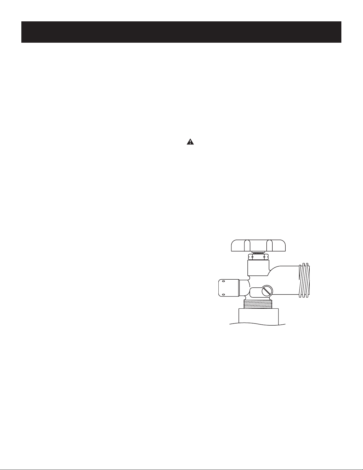
Note: Not all valve and cylinder combinations are compatible.
Check warning tag on valve and cylinder as well as external tting
threads.
All Broilmaster pressure regulators and hose assemblies require
Propane cylinders with a Type 1 connection device as illustrated.
See Figure 1.
Figure 1
B102188-0-0114Page 12
Pressure Regulator and Hose Assembly
The pressure regulator has an outlet pressure of not more than
eleven (11") inches water column. It must be connected to the
Propane gas cylinder’s valve outlet before the grill can be operated.
Caution: Operation of a Propane gas grill without the pres-
sure regulator and hose assembly will cause gas leaks which
could lead to re or explosion, resulting in property damage
or personal injury.
The pressure regulator’s tting must remain clean and free of nicks
and scratches. A dirty, nicked or scratched tting can cause a gas
leak, resulting in an explosion or re. Use only genuine Broilmaster
replacement parts unless otherwise specied by the manufacturer.
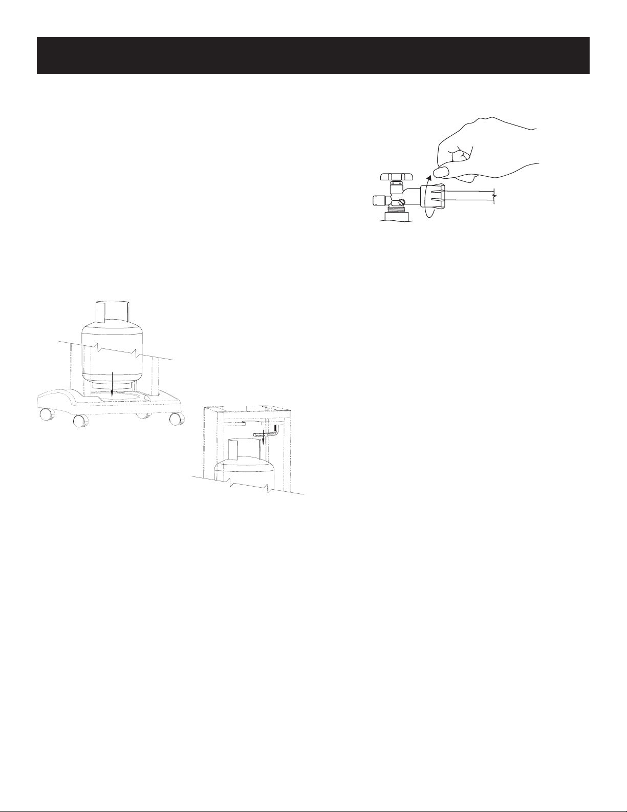
Connecting to Propane Gas / Cylinder Retention Means
ATTENTION: Propane gas cylinders that are acceptable for
use with this grill must comply with Cylinder Requirements, Page
10, and Connection Requirements, Page 11.
Position the cylinder in the opening in the bottom of the cart and
secure with the cylinder retaining bracket. See Figure 2.
Figure 2
PROPANE GAS GRILLS
Attach the pressure regulator to the Propane gas cylinder’s valve
using the plastic handwheel. Tighten in a clockwise motion to
achieve a gas tight seal. See Figure 3.
CLOCKWISE
Figure 3
Caution: Do not use a wrench or any other tool to tighten. Use
of a wrench or other tool will damage the plastic handwheel.
To disconnect the Propane gas cylinder, turn OFF the cylinder’s
valve and the grill’s control valve. Remove the regulator by turning
the plastic handwheel counterclockwise.
Caution: Assure hose does not touch the casting or mounting
components.

B102188-0-0114 Page 13
Connection Requirements
Broilmaster grills are not equipped with pressure regulators. Your
gas grill operates at a manifold pressure of seven (7") inches water
column.
Connect cart mounted Natural gas grills to a pre-installed gas sup-
ply line using the twelve (12’) foot exible hose and quick disconnect
kit which can be purchased from your local dealer.
Hazardous Locations and Conditions
• The LP gas cylinder must be arranged upright for vapor with-
drawal.
• Do not obstruct the ow of combustion and ventilation air.
• This grill should only be used outdoors in a well-ventilated space
must not be used in a building, garage, or any other enclosed
area.
• Keep all ammable substances away from the grill. These
include most aerosols and aerosol containers, gasoline and
similar liquids, paper and paper products, containers of grease,
paint, etc.
• Never store ammable materials or objects such as those
described above in the pedestal base.
• Never leave grill unattended while in operation.
• Never use any liquid in an attempt to control are-up.
• It may be necessary to adjust your grill away from the direction
of prevailing wind.
• Avoid wearing ammable and/or loose clothing such as long-
sleeves, neckties, scarves, aprons, etc., while the grill is in
operation.
• Avoid contact of hair to heat and ames.
Caution: The grill and its individual shutoff valve must be
disconnected from the gas supply piping system during any
system pressure testing at test pressures in excess of 1/2 PSIG.
Caution: The grill must be isolated from the gas supply piping
system by closing its individual manual shutoff valve during
any pressure testing of the gas supply piping system at test
pressures equal to or less than 1/2 PSIG.
Grill Location
When choosing the ideal location for your Broilmaster Premium
Gas Grill, remember this grill is designed for outdoor use ONLY.
You should never install or operate your grill in any building, garage,
or other enclosed area.
For your safety, this grill should not be installed or operated under
any combustible materials, such as carports, covered porches,
awnings, or overhangs.
Never install or operate your grill in or on any recreational vehicle
or boat.
CAUTION: The installation and operation of this grill at clear-
ances less than specied below may lead to the possibility of
re, property damage, or personal injury.
A minimum clearance of sixteen (16") inches is required from the
sides of the grill to any combustible material.
A minimum clearance of eighteen (18") inches is required from the
back of the grill to any combustible material.
Some examples of combustible materials are a wall, a fence, patio
furniture, or the wall of your home.
The area surrounding the grill should be clear to ensure proper
ventilation. Do not obstruct the ow of combustion and ventilation
air in any way. The ventilation openings on the propane cylinder
enclosure must also remain free and clear of debris.
Portable grills should be level and positioned away from direct wind
prior to each use.
WARNING: Do not install or operate this grill where gaso-
line or other ammable materials are used or stored. Failure
to comply with this warning could result in explosion or re
causing property damage or personal injury.
Gas Type
The type gas required for your grill can be determined from the
product identication label located on the grill’s control panel.
Questions regarding different types of gases should be directed to
your local gas supplier.
Caution: Never use Liquid Propane (LP) gas in a grill designed
for Natural gas, or Natural gas in a grill designed for Liquid
Propane gas. Questions regarding different types of gases
should be directed to your local gas company.
NATURAL GAS GRILLS
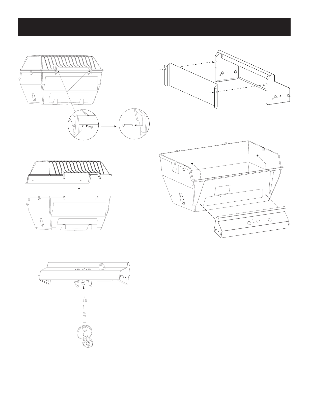
B102188-0-0114Page 14
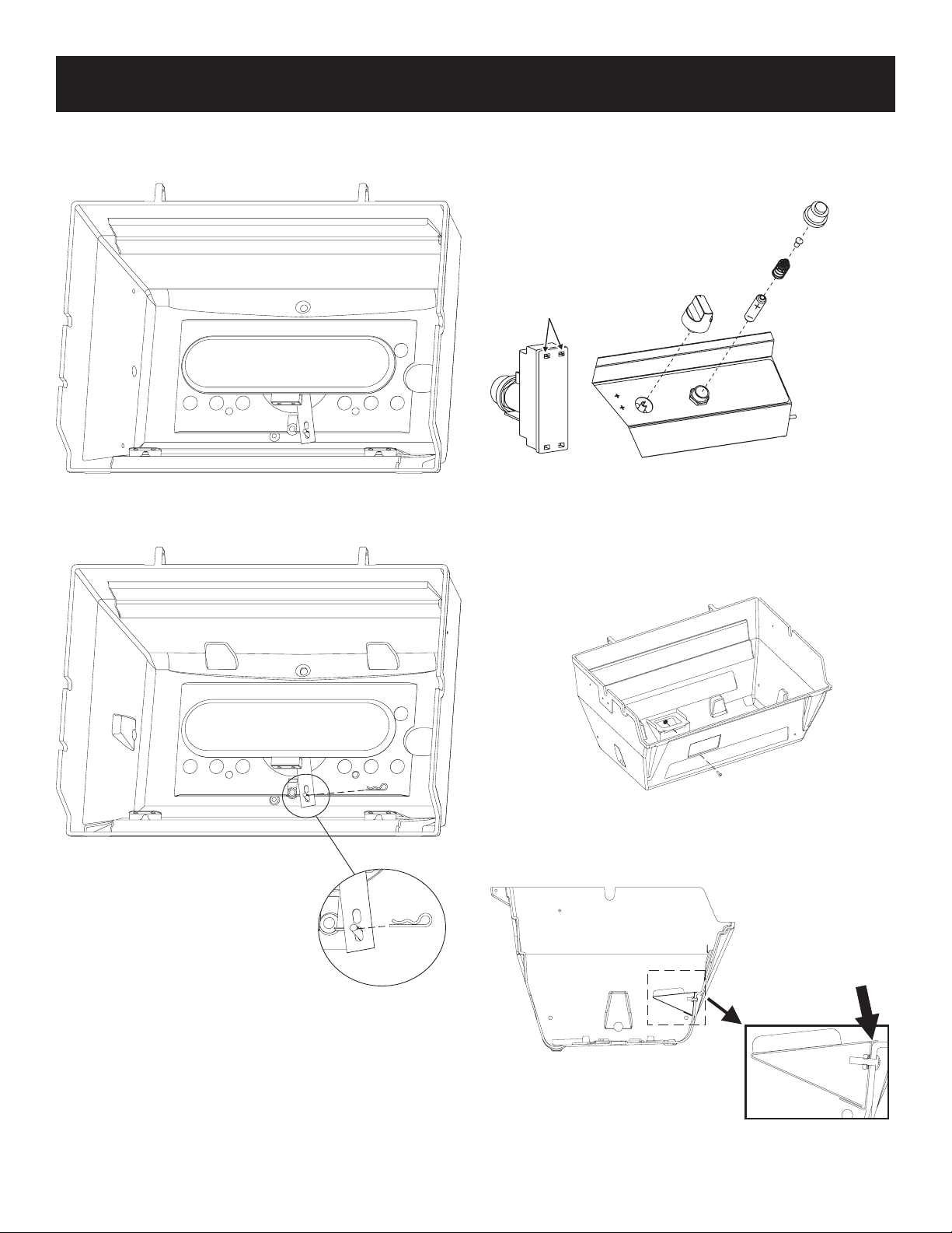
To ease installation remove grill body top from grill body bottom by
removing the two hinge pins and clips.
Figure 5
Install Hose and Regulator (For LP Models)
Attach the hose and regulator supplied with the unit as shown in
Figure 6.
Figure 6
GRILL ASSEMBLY
Figure 4
Install Heat Shield
Attach shield by inserting the shield over the studs. See Figure 7.
Figure 7
Install Control Panel
Attach control panel assembly to grill bottom with two (2) 10-24
keps nuts. See Figure 8.
Figure 8
B102188-0-0114 Page 15
GRILL ASSEMBLY
Ignitor Wire
Note: Install the Ignitor Ground Wire before installing the burner.
1. Connect the ground wire to the ground lug on the collector box
before installing the burner into the grill. See Figure 11.
Figure 11
Note: Install the Ignitor Ground Wire before installing the burner.
Install the Burner
1. Insert the burner assembly into the grill bottom with the venturi
tubes facing the front of the grill. See Figure 12.
2. Carefully slide the wires through the same hole in the bottom
of the grill.
Figure 12
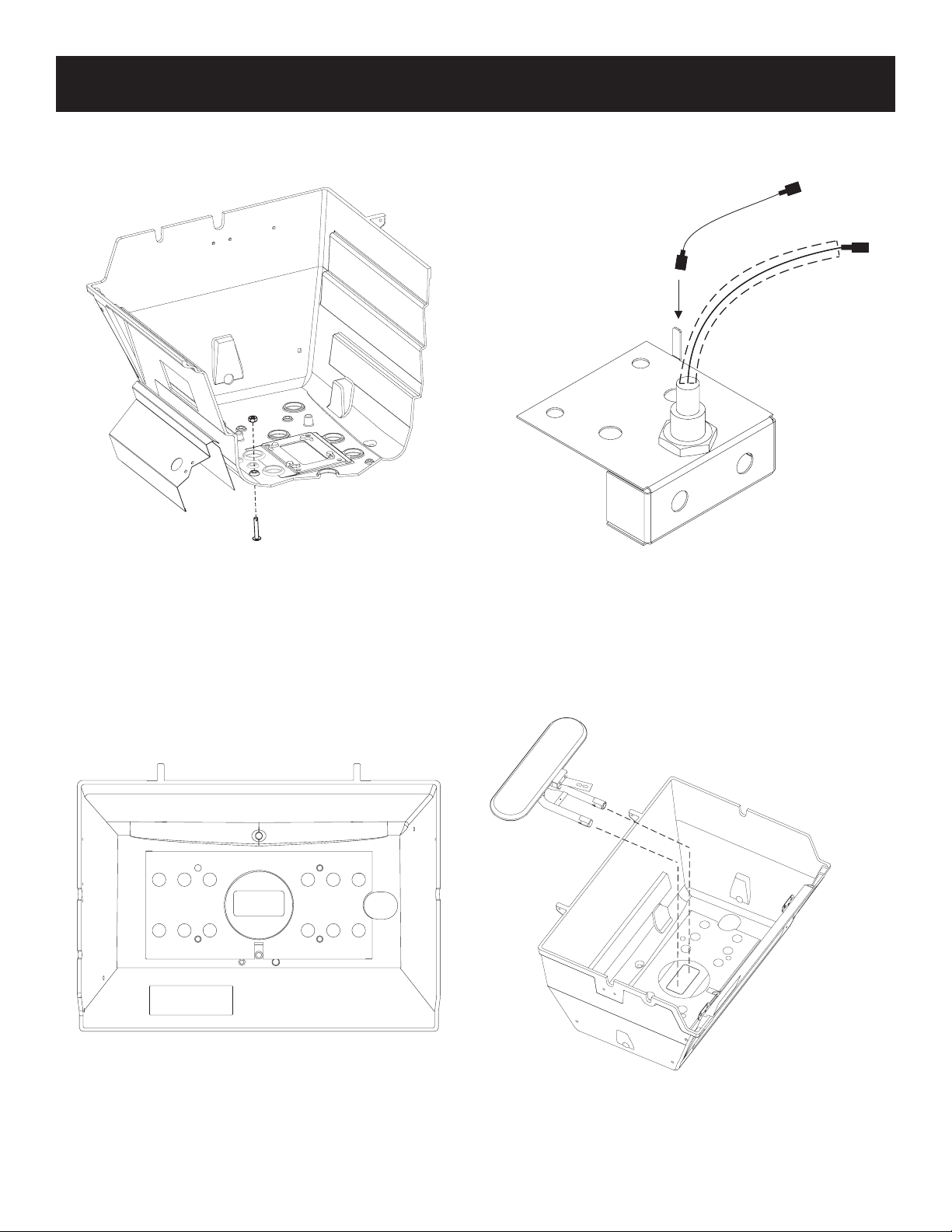
Burner Bracket Securing Bolt
1. Insert the 1/4-20 x 1 1/2 Phillips Truss Head Screw from the
underside of the grill and secure with the 1/4-20 Hex Nut. See
Figure 9.
Figure 9
Note: If the Grill Head is installed on a PCB1, PSCB or DCB1,
make sure the cart shield is not installed until the burner
bracket securing bolt is installed.
2. Install Grill Head on a Cart or Post Mounting (see Cart or Post
Installation Instructions that come with the mounting option).
Heat Shield / Wind Shield
Place the heat and wind shield in the grill bottom.
See Figure 10.
Figure 10
Note: The heat shield cannot be installed until after the grill is
installed on a post or cart.
B102188-0-0114Page 16
GRILL ASSEMBLY
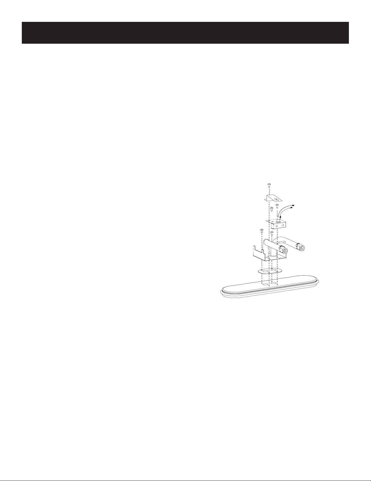
Connect Igniter Wires and Install Battery
1. Attach ground and igniter wires to the igniter as shown in Figure
15.
2. Remove push button cap and insert AA battery, positive side
UP, as shown in Figure 15.
IGNITOR
CONNECTIONS
Figure 15
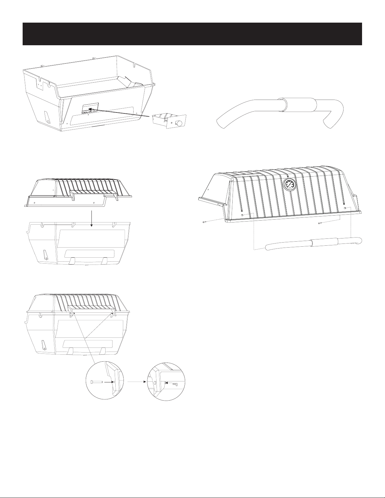
Smoker Drawer
1. Attach drawer support bracket to inside front of grill body with
10-24 x 3/4” machine screw and 10-24 nut. See Figure 16.
2. Slide the smoker box through the opening in the grill body. See
Figure 17.
Figure 16
3. Slide the venturi on to the valve assembly.
4. Raise the unsecured end of the burner bracket and slip it over
the 1/4-20 x 1 1/2 Phillips Truss Head Screw as shown in Figure
13. The screw will t into the hole on the burner bracket.
Figure 13
5. Slide the bridge pin through the hole in the 1/4-20 x 1 1/2 Phil-
lips Truss Head Screw as shown in Figure 14.
Figure 14
Lip resting on
casting ledge
B102188-0-0114 Page 17
Figure 17
Reinstall Grill Body Top to Grill Body Bottom
1. Secure grill body top to grill body bottom by replacing the two
hinge pins and clips. See Figures 18 and 19.
Figure 19
GRILL ASSEMBLY
Figure 18
Handle
For your added comfort a foam grip has been provided. See
Figure 20.
Tip: For ease of installation, slightly lubricate the front handle with
liquid soap before pushing the foam grip into place.
Figure 20
Fasten the front handle to the grill lid with two #10-24 x 1” screws.
See Figure 21.
Figure 21
Note: Install side shelves or side burner to side of grill at this
time. See installation instructions that came with the side shelves
or side burner for more information.
B102188-0-0114Page 18
GRILL ASSEMBLY
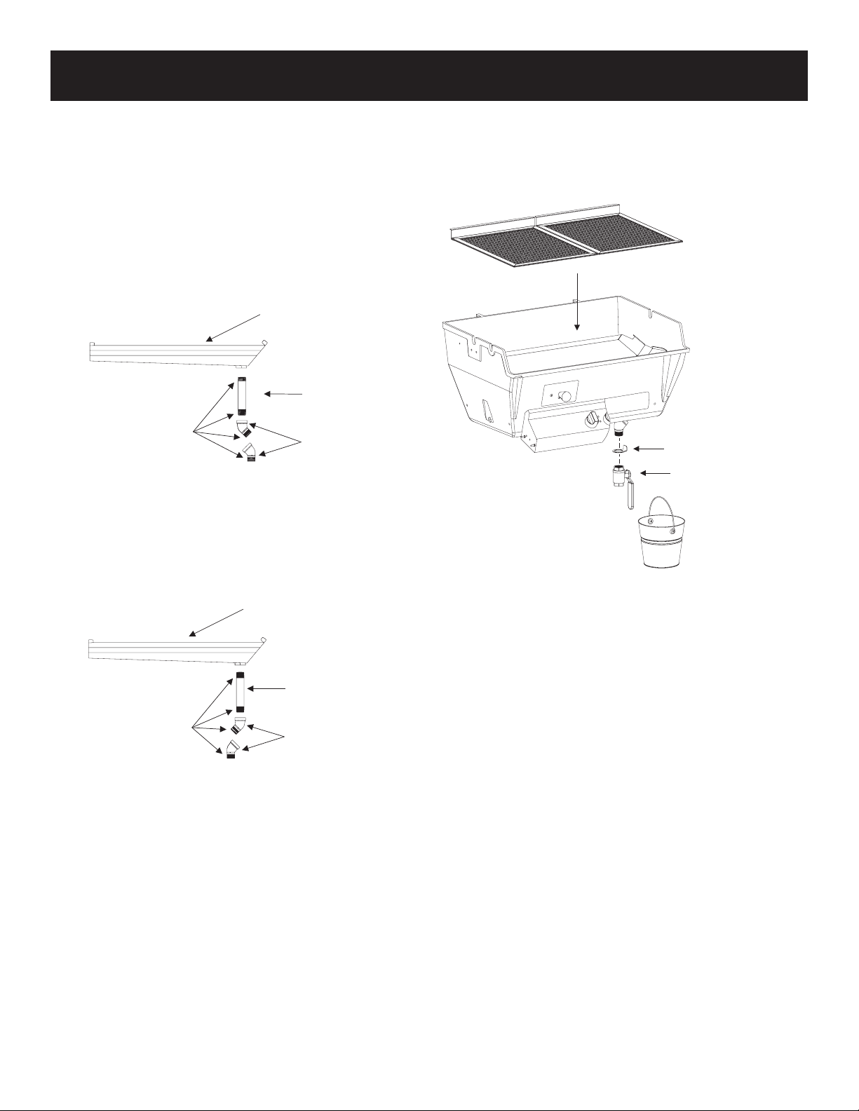
Assemble Drain Pan
Note: Drain pipe and valve coponents are packed inside the
smoker box.
1. Lightly spread pipe sealant on all threads before assembling
to the drain pan.
2. Thread the 3/4” pipe into the bottom of the drain pan and tighten.
3. Assemble the two 45° elbows as shown in Figure 23.
Note: Make sure of the mountings (posts, carts, etc.) being
used before tightening to ensure that the ttings are set to the
proper position.
DRAIN PAN
3/4” PIPE
45° ELBOWS
FOR USE ON ALL POSTS
AND DCB AND PCB CARTS
FOR USE ON PSCB CART
DRAIN PAN
3/4” PIPE
45° ELBOWS
PIPE SEALANT OR
TEFLONTAPE
PIPE SEALANT OR
TEFLONTAPE
Figure 23
Install the Drain Pan Assembly
1. Lower the drain pan into the lower casting with the drain pipe on
the right side. Pass the pipe through the oval hole in the bottom
of the casting, making sure the pipe extends out through the
bottom of the casting and the pan is sitting level on the holding
tabs. See Figure 24.
DRAIN BUCKET HANGER
DRAIN SHUT OFF VALV
E
Figure 24
2. Slide the drain bucket hanger into place over the pipe and
screw on the drain shut off valve and tighten.
Note: Position Drain Shut Off Valve so it does not interfere with
the wall of the grill head.
3. Set cooking grids in place.
Note: The grids are designed for two levels of cooking.
4. Hang the drip bucket on the drain bucket hanger.
NOTE: If the grill was installed on a cart, make sure to install the
cart’s heat shield before use.
B102188-0-0114 Page 19
Checking for Gas Leaks
Check for gas leaks every time you connect your Broilmaster pro-
pane gas grill to a Propane gas cylinder, when a connected cylinder
has not been used recently, or when either a natural or propane grill
is being used for the rst time.
Caution: Do not use an open ame when checking for leaks.
Checking for leaks with an open ame may lead to a re or
explosion, resulting in property damage or personal injury.
To check for gas leaks:
1. Use dish washing liquid and a little water to make a soapy solu-
tion.
2. Turn OFF the knob on the control panel.
3. Turn ON the gas at the supply or cylinder. A hissing sound
indicates a leak. Turn OFF the gas and repair the leak.
4. Apply the soapy water solution to all gas connections.
5. Look for bubbles. Bubbles indicate a leak.
6. If there are bubbles turn OFF the gas and repair the leak.
7. Turn the gas back ON and repeat the above procedures until
all leaks are repaired.
Air Shutter Adjustment
The venturi air shutter(s) are preset at the factory so that after ve
minutes the burner ames are blue with well dened cones. If,
after ve minutes the ame is yellow, or there is a gap between
the burner and the ame, adjust the venturi air shutter as follows:
1. Turn gas OFF and let the burner cool.
2. Loosen shutter set screw
3. Close the air shutter to the minimum opening.
4. Light the burner, wait ve minutes and then carefully open the
air shutter until the ame is blue and well dened.
5. Retighten the set screw.
Heat Indicator Recalibration
The heat indicator can be recalibrated if needed. Remove the heat
indicator from the grill and place the probe end in a pot of boiling
water. Set the heat indicator by turning the nut on the back until it
reads 212 degrees. The indicator is now set.
OPERATION - PROPANE & NATURAL GAS GRILLS
Lighting Instructions
Using the Ignitor
Caution: If a burner fails to light after 5 seconds, turn the
burner OFF for 5 minutes and open grill lid, to allow the gas
to clear, then try again.
1. Turn knob on the grill CLOCKWISE to the OFF position.
2. Turn ON gas at the source.
3. With the grill lid open, push and turn the burner valve knob
COUNTERCLOCKWISE to Hi.
4. Push and hold the ignitor button until the burner lights (approxi-
mately 5 seconds).
5. If a burner does not light, turn OFF all gas and refer to the
Troubleshooting section of this manual.
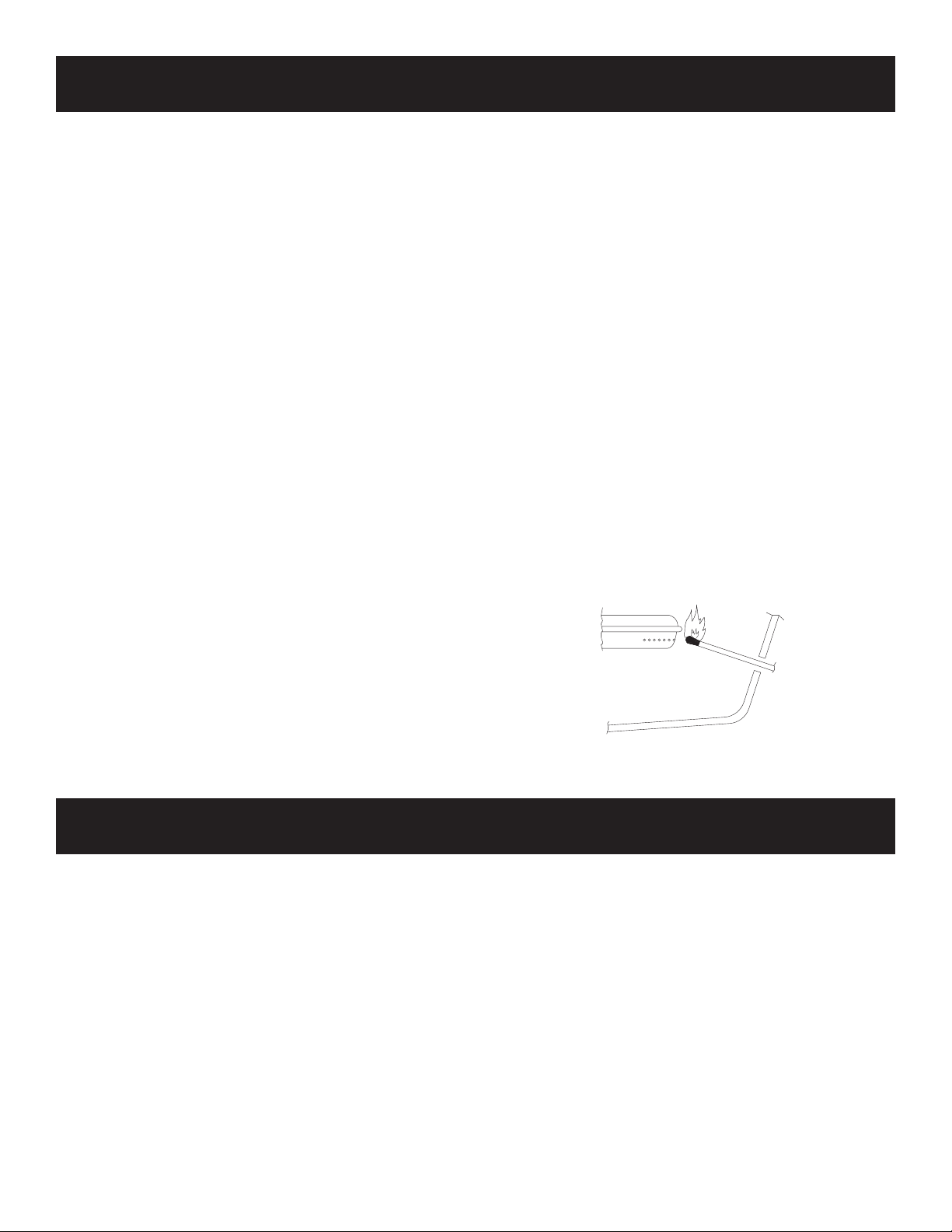
Using Matches
Caution: If a burner fails to light after 5 seconds, turn the
burner OFF for 5 minutes and open grill lid, to allow the gas
to clear, then try again.
1. Turn knob on the grill CLOCKWISE to the OFF position.
2. Turn ON gas at the source.
3. Open the grill lid.
4. Insert a burning long wooden match through the lighter hole on
either side of the grill. See Figure 25.
5. Turn the burner valve knob COUNTERCLOCKWISE to HI.
6. If a burner does not light, turn OFF all gas and refer to the
Troubleshooting section of this manual.
Figure 25
Before Cooking
Before cooking on a grill for the rst time, burn off any manufacturing
process oil residue.
1. Raise the grill lid.
2. Light grill burner.
3. Burn on HI for ten minutes.
4. Close the lid and burn on HI for an additional ten minutes.
5. The grill is now ready for use.
Preheating
Before cooking on a gas grill, allow the grill to preheat on HI for 15
minutes with the lid closed.
This uses very little fuel and provides better avor.
OPERATION
Electrical Accessories
• If an electrical accessory is used on your grill, the accessory
must be electrically grounded in accordance with local codes or,
in the absence of local codes, with the National Electric Code,
ANSI/NFPA 70. In Canada, the electrical accessory must be
electrically grounded in accordance with the applicable section
of the current Canadian Electrical Code, CSA C22.1.
• Any electrical accessory should be equipped with a three-
prong (grounding) plug, and plugged into a properly grounded
three-prong receptacle or wall outlet. Do not cut or remove
the grounding prong from the plug.
• If an extension cord is required, use only a three-prong cord and
plug into a properly grounded receptacle as described above.
• Do not expose an electrical accessory to water. Avoid using
any electrical accessory in wet weather as it may present a
shock hazard.
• Keep any electrical cord and fuel supply hose away from all
heated surfaces.
B102188-0-0114Page 20
MAINTENANCE
Cleaning the Grill
Caution: To prevent injury, use care when cleaning a hot grill.
Note: Do not use a commercial cleaner on the cooking grid.
Do not brush grids while they are hot. Do not scrape grids.
Grids and Drip Pan
The grids are made of high quality stainless steel and should be
brushed with a brass brush while the grill is still warm.
The drip pan is made of high quality stainless steel as well and can
be cleaned with a scraping tool. The pan must be kept clean of heavy
build-up for the grill to perform properly and to reduce are-ups.
Clean as needed or approximately every 10 uses.
Burn Off
This process is much like that used in self-cleaning ovens and is
most efcient when completed after each use of the grill.
Caution: Do not open the grill during the burn off process.
Opening the grill during the burn off process may cause a
sudden grease re are up that could burn your face and arms.
Wait until the grill has cooled before opening.
1. Turn gas knob to HI. Close lid and allow the grill to burn for ten
minutes, or until no smoke is present. Do not allow the grill to
burn for more than 30 minutes.
2. Turn gas knob and supply to OFF and allow the grill to cool.
Grill Bottom
Once or twice a year remove cooking grids and drip pan to clean
the interior of the grill. Scrape off baked on residue with a putty
knife or brass brush and rinse with water.
Burner Maintenance
Stainless steel burners often turn reddish brown after use. This does
not affect the performance of the grill. When cleaning the interior of
the grill, remove the burners and clean with a brass brush. Wash
with water and a mild detergent.
Drip Pipe and Valve
Drain pipe and valve must be kept clear of grease and food particles
to allow the grease to drain properly. To clear the drain pipe and
valve, run a exible drain brush through both and remove.
Bucket
The bucket can be stored under the grill lid when the grill is not in
use.
Venturi Tubes
The venturi tubes allow air and gas to mix prior to burning, thus
ensuring an efcient ame. Spiders or other small insects may
build webs or nests inside the tubes obstructing air ow. Fire, or
ashback, can occur, in and/or around obstructed venturi tubes and
can cause damage to components beneath the grill or an unsafe
condition. To reduce risk, inspect and clean the Venturi Tubes at
least twice monthly when spiders are active. If the grill has been
unused for an extended period of time inspect the tubes before
using the grill.
Clean venturi tubes as follows:
1. Remove the cooking grids and drip pan.
2. Remove the burner from the grill.
3. Lay the burner face down and remove the four retaining screws
from the venturi tube plate and the burner. See Figure 26.
4. Use a small exible brush to remove any debris for the tube(s).
5. Flush with water.
6. Allow the tube(s) to dry before reinstalling.
7. Reinstall the venturi tubes, igniter and burner bracket to burner.
Figure 26
Exterior
Clean regularly with a solution of mild detergent and hot water.
Touch-up paint is available from your dealer. Broilmaster protec-
tive covers are recommended. Stainless steel components can
be easily cleaned with a spray-on stainless steel cleaner found in
most hardware stores.

B102188-0-0114 Page 21
Although the manufacturer has attempted to ensure that your grill will operate properly and satisfactorily,
sometimes problems do arise. The following troubleshooting guide lists several possible problems and
their probable cause and solution.
Problem Cause Solution
Burner will not light. Out of gas Rell LP gas cylinder. If natural model, turn
on gas at source.
Gas injector not inserted in venturi tube. Realign/engage gas injector with the ven-
turi tube.
Clogged gas injector. Remove gas injector from gas control as-
sembly and clean.
Obstruction in gas line. For propane models, ensure gas valve on
cylinder is OFF. Remove exible hose and
blow out any debris.
Spider webs in venturi tubes. Clean venturi tubes. See Maintenance
Section.
Misalignment of collector box and burner. Position electrode properly. Clean collector
box.
Dead battery. Replace with AA battery.
Inadequate grill temperature. Poor combustion. Adjust air shutter.
Misalignment of venturi tube and gas injec-
tor.
Realign/engage gas injector with the ven-
turi tube.
Inadequate gas pressure. Contact gas supplier for assistance.
Incorrect orice/valve setting. Refer to gas conversion instructions in this
manual.
Flames blow out. Cold grill. Preheat grill at least 15 minutes on HI with
the grill lid closed.
Misalignment of burner tube and gas injec-
tor.
Realign/engage gas injector with the
burner tube.
Poor combustion. Adjust air shutter.
Extreme wind. Turn or shield grill.
Yellow ames. Air shutter improperly set. Open air shutter.
Spider webs in venturi tubes. Clean venturi tubes. See Maintenance
Section.
Seasoning salts on burner. Clean by washing burner with mild deter-
gent.
Oil lm on burner. Allow burner to operate on HI for 10-15
minutes.
TROUBLESHOOTING
B102188-0-0114Page 22
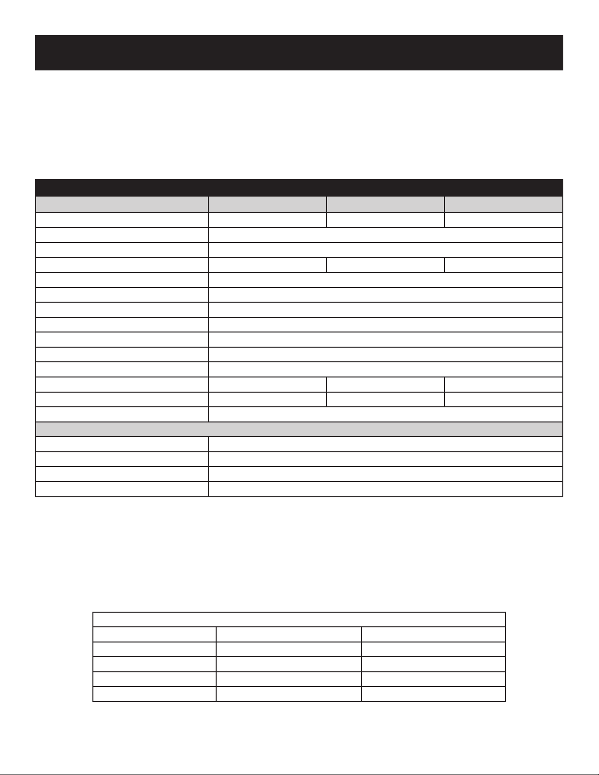
COOKING TIPS
Cook Food To Proper Temperatures
Cooking food safely requires that you raise the internal temperature of the meat high enough and for a long enough period
of time to kill any food-borne bacteria that may cause illnesses.
Color is not the best indicator that food is safe to eat. Use a high-quality probe thermometer to be sure your food is prop-
erly cooked. Place the tip of an instant-read thermometer into the center of the thickest part of the food but at least 1/2
inch deep. Read the temperature after about 10 seconds. Follow the temperature guidelines for the type of food you’re
cooking.
The following guidelines are from the U.S. Food and Drug Administration Center for Food Safety and Applied Nutrition.
Cook to Internal Temp
Meat & Poultry Medium Rare Medium Well Done
Fresh Beef - Medium Rare 145°F 160°F 170°F
Ground turkey, chicken 165°F
Ground veal, beef, lamb, pork 145°F with 3 minutes of rest and then turn
Fresh Pork - Medium 160°F 170°F
Chicken - whole 165°F
Turkey - whole 165°F
Poultry breasts, roast 165°F
Poultry thighs, wings 165°F
Stufng (cooked alone or in bird) 165°F
Duck and goose 180°F
Fresh Veal - Medium Rare 160°F
Fresh Lamb - Medium Rare 145°F 160°F 170°F
Ham - fresh (raw) 145°F 160°F 170°F
Ham - pre-cooked (reheat) 140°F
Seafood
Fish Cook until esh turns opaque and akes easily with a fork.
Shrimp, lobster, crab Cook until shells turn red and esh becomes pearly opaque.
Scallops Should turn milky white or opaque and rm.
Clams, mussels, oysters Cook until shells open.
The Qrave Grill is an indirect gas grill. This means that the ame never comes in contact with the food and does not are
up. The drip pan vaporizes all the drippings into smoke and moisture. This produces tastier and juicier foods. You will be
amazed at how easy it is to cook all your favorites and more; perfect every time.
The following instructions are to be used as a guideline. You may need to adjust the cooking times and temperatures to
suite your own taste.
When cooking on the Qrave Grill, it is essential that the lid remain closed. This not only keeps the temperature constant,
but holds in the moisture as well.
The drip pan drain valve should be open when grilling. This allows the excess grease to continuously drain into the catch
bucket. The only time the drain valve should be closed is when cooking with a liquid in the pan.
Quick Temperature Reference
Valve Knob Setting Approximate Temperatures Types of Cooking
One Valve Knob Low 220°F to 250°F Slow Cooking & Smoking
Both Valve Knob Low 320°F to 350°F Roasting & Baking
Both Valve Knob Medium 375°F to 425°F Roasting & Baking
Both Valve Knob High 450°F to 550°F Grilling & Steaming
*The above temperature settings are a guide, the temperatures may vary due to wind and outside ambient temperatures.

B102188-0-0114 Page 23
COOKING TIPS
Grilling
1. Place the cooking grids in the low position.
2. Preheat your grill with both valve knobs set to High for 15
minutes.
We recommend that when grilling, the valve knobs should remain
on high. This cooking method is great for hamburgers, steaks,
chops, etc.
Roasting
When roasting it is important to remember that it is just like cook-
ing in your oven. Hint: You may want to ll the drip pan with water
or a marinade to create more avor and moisture.
1. Close the drip pan drain valve and ll the pan about half full
with water or marinade.
2. Set the cooking grids at the low position.
3. Preheat the grill with both controls on High for 15 minutes.
4. Set the valve knobs to the desired temperature using the
Quick Temperature Reference Chart.
While cooking, monitor the heat indicator on the grill and adjust
temperature as necessary.
More water or marinade may need to be added to the pan as it
evaporates during cooking.
Roasted chicken, turkey or pork roasts will never taste better.
Baking
Before starting, make sure the drip tray is clean.
1. Place the cooking grids at the high position to remove the
food away from the direct heat.
2. Preheat your grill with both valve knobs set to High for 15
minutes.
3. Set the valve knobs to the desired temperature using the
Quick Temperature Reference Chart.
Use the heat indicator on the grill to more accurately adjust the
temperature.
Even cookies, pizza and desserts can be made on the Qrave Grill.
Steaming
Before starting, make sure the drip tray is clean.
1. Set the cooking grids at the low position.
2. Close the drip pan drain valve and ll pan with water. Be care-
ful not to over-ll the pan.
3. Preheat your grill with both valve knobs set to High for 15
minutes.
4. The valve knobs will remain on high for steaming. Cook until
desired taste. More liquid may need to be added to the pan as
it evaporates during cooking.
Vegetables and seafood taste great when steamed in the Qrave
Grill.
Smoking
The Qrave Grill is equipped with a front load smoker box.
1. Soak your avor smoking chips in water for about 15 minutes.
This will make the chips burn slower and create more avor.
2. Remove the smoker box and ll with the soaked chips and
then replace.
3. Set the cooking grids at the low position.
4. Preheat your grill with both valve knobs set to High for 15
minutes or until you detect smoke.
5. Place the food on the grill and adjust the temperature as de-
sired.
Note: The left knob controls the amount of heat under the
smoker box. The smoker box is designed to be used on
low for best results.
This works great for adding smoke avor when grilling and roast-
ing.
Slow Cooking with Smoking
The Qrave Grill has dual controls for more control for those low
temperatures needed for slow cooking.
1. Adjust the cooking grids to the high position.
2. Close the drain valve and add water or marinade to the drip
pan. It is recommended to slow cook with a liquid in the pan
to keep the food from drying out. More liquid may need to be
added to the pan as it evaporates during cooking.
3. Preheat your grill with both valve knobs set to High for 15
minutes.
4. Turn off the right valve knob and turn the left valve knob to
low. Hint: The left valve knob controls the heat on the smok-
er box. Add water-soaked avor chips to the smoker tray as
needed. Most chips will last about an hour before needing to
be replaced.
Turn the food once an hour when slow cooking.
Slow cooking with a Qrave Grill could mean the best ribs or brisket
your family has ever tasted.
CAUTION: Always use an oven mitt when removing smoker
box while grill is hot. Make sure chips are cooled before emp-
tying smoker box.
B102188-0-0114Page 24
BROILMASTER
A Division of Empire Comfort Systems, Inc.
918 Freeburg Ave.
Belleville, Illinois 62220
Visit our web site at www.broilmaster.com
If you have a general question about our products, please e-mail us at [email protected].
If you have a service or repair question, please contact your dealer.
Model No. Dealer
Serial No. Dealer Phone No.
Gas Type: Propane Natural Date of Purchase
Your Broilmaster Premium Gas Grill is identied by model number, serial number, and
gas type. This information is provided on a product identication label located on the
grill’s control panel. For your convenience, complete this section for future reference
when contacting your dealer.
COOKING TIPS