
CRAFr.3
_xeRouter Table
:CAUTION!_ReadAllInstructionsCarefully
(RouterNotIncluded)
i
i
Pa_No.49LCN:59
Solday:
SEARS,ROEBUCKAndCO.
3333 BeverlyRoad,
HoffmanEstates,IL60179
Made In U,S.A.
Printed h7U,S.A.

FAILURETOHEEDALLSAFETYANDOPERATINGINSTRUCTIONS
ANDWARNINGSREGARDINGUSEOFTHISPRODUCTCANRESULT
IN SERIOUS80DILYINJURY.
GENERALSAFETYINSTRUCTIONSFORPOWERTOOLS
1. KNOWYOURPOWERTOOL
Readthe owner'smanualcarefully.Learnits applicationand
limitationsaswell asthe specific potentialhazardspeculiarto this
toot.
2. GROUNDALLTOOLS(UNLESSDOUBLEINSULATED)
Iftool isequippedwith anapproved3-conductor cordand a3-
prong groundingtype plug,it should bepluggedintoa threehole
electricalreceptacle,Ifadapteris usedto accommodatea two-
prong receptacle,theadapterwire must be attachedto known
ground,(usuaflythescrewsecuring receptaclecoverplate).Never
removethird prong.Neverconnectgreengroundwireto a
terminal.
3. KEEPGUARDSIN PLACE
Inworking order,andin properadjustmentand alignment,
4. REMOVEADJUSTINGKEYSANDWRENCHES
Forma habitof checkingto seethat keysandadjusting wrenches
areremovedfrom too!beforeturning it on.
5. KEEPWORKAREACLEAN
Clutteredareasandbenchesinvite accidents,Floormustnot be
slipperyduetowaxorsawdust.
6. AVOIDDANGEROUSENVIRONMENT
Don't usepowertools in dampor wet locationsor exposetllem to
rain.Keepwork areawel!lighted: Provideadequatesurrounding
work space.
7. KEEPCHILDRENAWAY
All visitors shouldbe keptasafedistancefrom workarea.
8. MAKEWORKSHOPKID-PROOF
Usepadlocks,masterswitches, or removestarterkeys.
9, DON'TFORCETOOLS
It wilt do thejob betterand saferatthe ratefor which it was
designed,
10. USERIGHTTOOL
Don'tforcetoot or attachmentto do a job it was not designedfor.
11. WEARRIGHTAPPAREL
Do notwearlooseclothing,gloves,necktiesor jewelry (rings,
wrist watches)to getcaugt]tin moving parts,Nonslipfootwearis
recommended,Wearprotectivehair coveringto contain long flair.
Rolllong sleevesabovethe elbow.
12. USESAFETYGOGGLES(HeadProtection)
WearSafetygoggles(mustcomplywith ANSI'Z87,1)atalltimes.
Also, usefaceor dust mask,if cuttingoperationisdusty,andear
protectors (plugsor muffs) during extendedperiodsofoperation.
13. SECUREWORK
Useclamps or a viseto holdworkwhenpractical,It'ssaferthan
using your hands,andit frees both handsto operatetool,
14. DON'TOVERREACH
Keepproperfootingandbalanceatatftimes.
i5. MAINTAINTOOLSWITHCARE
Keeptoolssharpandcleanfor bestand safestperformance.
Follow instructionsfor lubricatingand changingaccessories.
16. DISCONNECTTOOLS
Beforeservicing,whenchangingaccessoriessuch as blades,bits,
cutters,etc.
17. AVOIDACCIDENTALSTARTING
Make sureswitch is in "OFF"positionbeforepluggingin.
18. USERECOMMEND_EDACCESSORIES
Consulttheowner's manualfor recommendedaccessoriesand
follow the instructions,Theuseof improperaccessoriesmay
causehazards.
19. NEVERSTANDONTOOL
Serious injurycould occur if thetool is tippedor if thecutting tool
is accidenta!lycontacted.Donotstore materialsaboveornearthe
tool makingit necessaryto stand onthe tool to reachthem.
20. CHECKDAMAGEDPARTS
Beforefurther useof thetool, any guardor other partthat is
damagedshould becarefullycheckedto ensurethat it will operate
properlyand perform its intendedfunction. Checkforalignmentof
moving parts,binding of moving parts,breakageof parts,
mounting,andany otherconditionsthat may affect its operation.A
guard or anyother partthat is damagedshould be properly
repairedor replaced.
21. DIRECTIONOFFEED
Feedwork intoa bladeor cutteragainstthedirection of rotation of
the bladeor cutteronly.
22. NEVERLEAVETOOLRUNNINGUNATTENDED
Turn poweroff. Don't leavetool untilit comestoa completestop,
ENERALSAFETYI UCTI THE
LEWITHUNITIZEDFENCE.
1. ALWAYSUSEEYEPROTECTION
Theoperationof anypowertoo!canresult inforeignobjectsbeing
thrownintotheeyes,which canresult in severeeyedamage.
Alwayswearsafetygogglesbeforecommencingpowertool
operation,Safetygogglesareavailableat Searsretailor catalog
stores,
2. KEEPHANDSCLEAROFBITSANDWORKINGAREA
3. MAKEANOUSEAPUSHSTICKTOMOVESMALL
WORKPIECESACROSSTHECUTTINGAREA.
4, KEEPROUTERCLEANAFTEREVERYUSE,CLEANSAWDUST
OFFTHEROUTER.
5. YOURROUTERTABLEiS PROVIDEDWITHADUST
COLLECTINGATTACHMENTALWAYSUSESHOPVACFORALL
ROUTINGOPERATIONSREQUIRINGUSEOFFRONTSIDEOF
UNITIZEDFENCE.(FRONTSiDEtS THESIDEWITHTHE
CRAFTSMANLABEL).
NOTE:Motors usedon wood-working toolsareparticularly
susceptibleto theaccumulationof sawdustandwood chips and
should be"vacuumed"frequentlyto preventinterferencewith
normal motor ventilation.
6. CHECKFUNCTIONOFGUARDBEFOREEACHUSE.REMOVE
ALLDUSTANDCHIPSFROMGUARDAREAASNEEDEDTO
MAINTAINGUARDFUNCTION.
7. NEVERPUTYOURFINGERSUNDERTHEGUARDWHENTHE
ROUTERISPLUGGEDIN.
8, ALWAYSUSETHEROUTERTABLEFENCETOGUIDETHE
WORK.DONOTWORKFREEHAND.
Whenusingpilottype bits,keepthefencesascloseto the pilotas
possibleto provideadditionalbackupand additionalguidanceand
to avoidchancesof an accidentandpossiLllepersonalinjury, ,
9. ALWAYSFEEDAGAINSTTHEROTATIONOFTHECUTTER
WHENROUTINGONTHEROUTERTABLE.FEEDWORKPIECESIN
THEDIRECTIONOFTHEARROWASSHOWNONTHELABELON
THESIDEOFTHEFENCEBEINGUSED(WHENFACINGTHE
TABLEFRONT).
10. FORALLEDGECUTTINGANDENDCUTrlNGOPERATIONS,
USEFRONTSIDEOFUNITIZEDFENCE.USEBACKSIDEOF
FENCEONLYFORROUTINGOPERATIONSAWAYFROMEDGEON
THEUNDERSIDEOFWORKPtECESUCHASGROOVING,
FLUTING,VEINING,CROWNMOLDING,ETC.
11. WHENENDCUTTINGONWORKPIECES'4"WIDEORLESS,
CLAMPANDHOLDANDFEEDTHEWORKPIECEWITHTHEPUSH
BLOCKUSINGBOTHHANDS,ASSHOWNiN FIG.#23. KEEP
FINGERSCLEAROFBITWHENMOVINGWORKPIECEACROSS
THECUTTINGAREA.NEVERPLACEYOURHANDSLOWERTHAN
THETOPOFRETRACTABLEGUARD.
12. ROUTERBITSARE_:_rREMELYSHARP.
Beextracarefulwhenworking around them.
13, SOMEROUTERS,WHENUSEDIN AN UPSIDEDOWN
POSITION(SUCHASONAROUTERTABLE),WILLFALL(OR
DROP)OUTOFTHEROUTERBASEWHENTHEBASECLAMPIS
LOOSENED+IT IS THEREFOREABSOLUTELYNECESSARYTO
SUPPORTTHEROUTERMOTORFROMBELOWWHENTHEBASE
CLAMPIS LOOSENEDTOMAKEADJUSTMENTS,ORFORANY
OTHERREASON.
t4. ALWAYSLOOKUNDERTHETABLEATTHESWITCHWHEN
TURNINGTHEROUTERON!OFFANDTOUCHNOTHINGBUTTHE
SWITCH,NEVERREACHUNDERTHETABLEWHENROUTERtS
RUNNINGFORANYOTHERREASON.
NOTE:It isfar more safeand convenientto usea "Craftsman
+25183 RouterTableSwitchpackage".This switch providesa key
o 1
peratedON/OFFbutton-whichallowsfast andeasyaccesswhen
and if it becomesnecessaryto turn the router"OFF"quickly,The
keycan beremovedto renderthe switchinoperableto
unauthorizedpeople.
15. MOUNTROUTERTABLEFIRMLYANDSECURELYTOA
WORKSURFACEBEFOREUSE.FAILURETODOSOCOULD
CAUSETABLETOTiP OVERORSLIDEDURINGOPERATION
RESULTINGIN PROPERTYDAMAGEAND/ORSERIOUSBOOILY
INJURY.
16. BEFOREMAKINGANYCUT,UNPLUG
ROUTERANDRETRACTGUARDTO
MAKEABSOLUTELYSURETHATRETRACTABLEGUARDCLEARS
THEROUTERBIT,ANDTHEGUARDISFUNCTIONING
NORMALLY.SEEFIG.#16.
17. WARNING:ROUTERVIBRATIONS
SOMETIMESCANCAUSEFASTENERS
FORTHETABLE,THEROUTERANDTHEUNITIZEDFENCETO
GETLOOSErPERIODICALLYCHECKFASTENERSTOMAKESURE
THEYARETIGHTANDSECURE,
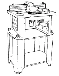
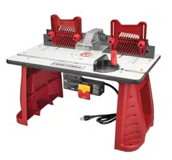
INTRODUCTION
Howoftenhaveyou neededa largeguiding surfaceon aroutertable?YourCraftsmanRouterTablewith UnitizedFencecomeswith ttle
following:
• A unique4" high unitizedfencedesignedtoassist end grain
routingfor makingtenons,slidingdovetailsandtongue and
groovejoints along with most edgeand facecutting operations.
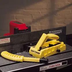
• A speciallydesignedpushblockwith quick clamp for back up
and clampingboardsup to 4"width for endgrain routing.
• An accurateand quick adjustingjointing fenceadjustableto
properjointing depthof cut.
• Reversingfeatureof unitizedfencedesignedto enablerouting
operationslikegrooving,fluting, veiningandcrown moldingetc.
up to 2_" awayfrom theedgetowardsthemid,dieofthe board.
• Twoguardsfor operationoneithersideof ihe unitizedfence.
• Dustco!lectingattachmentfor most sllop vacuumhookups,
• Extensionsthat providea largework surface.
If orderto facilitatehandlingand minimizeany damagethat might occur during shipment,your newroutertableis packaged
unassembled.We knowyouare anxiousto seewhat yOurnewtoo! wil! do, buta few minutesspent nowcarefullyreadingthefollowing
instructionswill result in lessfrustration and moreenjoyableoperationlater,
Startbycheckingandaccountingfor allthe looseparts,If anypartsare missing,contact your localCraftsmanretailor hardwarestore
outletfor replacement.
OPTIONALROUTERTABLEACCESSORIES
#25326CRAFTSMANUNIVERSALADAPTERPLATE,for mounting non-Craftsman1/4"shank routersto Craftsmanrouteraccessories.
#25183CRAFTSMANROUTERTABLEPOWERSWITCH,for turning routerand otheraccessories"on" and"off" from the front of the
routertable, i
#25468CRAFTSMANGUIDEMASTERRouterTablePushShoe,aids in pushshoeand hold down operations,accuratemeasurementand
routertablesetup,transformsinto a miter gauge,and givesquick set up for 1/2"slidingdovetailjoints.
#25489CRAFTSMANROUTERTABLEFLOORSTAND,placesroutertablesat convenientworking height,hasadjustablefloor levelers,
andtwo steelshelvesfor storage,
UNPACKINGANDCHECKINGCONTENTS
Referto PartsList on Page16
YOUMUSTREADANDUNDERSTANDALLTHEINSTRUCTIONSCOMPLETELYBEFOREATTEMPTINGTO
ASSEMBLEANDOPERATEYOURROUTER/ROUTERTABLE,
TOOLSREQUIRED
, A smallandmediumsizescrewdriver.
• Asmallormediumsizeadjustablewrench,
• Anelectricalor hand drill with 1/8"drill bit,
• Hammer
ASSEMBLYOFEXTENSIONSANDLEGS
t. ToassembletheEXTENSIONSand LEGSto ROUTERTABLE,
placetable,top sidedown, on a smooth, flat surfi_ce,and position
theLEGSand EXTENSIONSrelativeto the TABLEasshown in
Figure1.htsertthe#10-32 x Yi'screwthrough the LEGand install
lock washerandnut. This is to bedone for eachtableleg.
2, Makesureall screws andnutsaresecurelytightened,
3.Turnthe tabletop sideup andcheckto seethat tfm
EXTENSIONSareevenwith or slightly belowthe tabletop.
4, In no caseshouldthe EXTENSIONSbehigher thanthe table, or
elsetheymay interferewith theworkpieceduring routing causing
a conditionthat canresultin possibleserious injury.
5. If the extensionsarehigherthanthetop ofthe table, loosenthe
screwsholdingtheEXTENSIONSand repositionthem sothey art;
evenwith or slightly lowerthanthetop oftable, SECURELY
TIGHTENALL SCREWSANDNUTSAGAIN,
6.Todoublecheck,slidea flat pieceof woodalongthetop of the
tableboth directions,Makesurethat theend of the wood moves
freelywithout contactingthe edgeof theEXTENSIONnextto table,
DONOTPLACEHEAVYOBJECTSORPRESS
HEAVILYONTHEEXTENSIONSORELSE
THEYMAYBEDAMAGEDCAUSINGACONDITIONTHATMAY
CANRESULTIN POSSIBLESERIOUS80DtLYINJURYDURING
ROUTING.
FIGURE 1
MOUNTINGROUTERTOTABLE
ALWAYSUNPLUGROUTERBEFOREMOUNTING(Thetablewill acceptCraftsman3 hole 6 in.diameterbase).
, i:f •
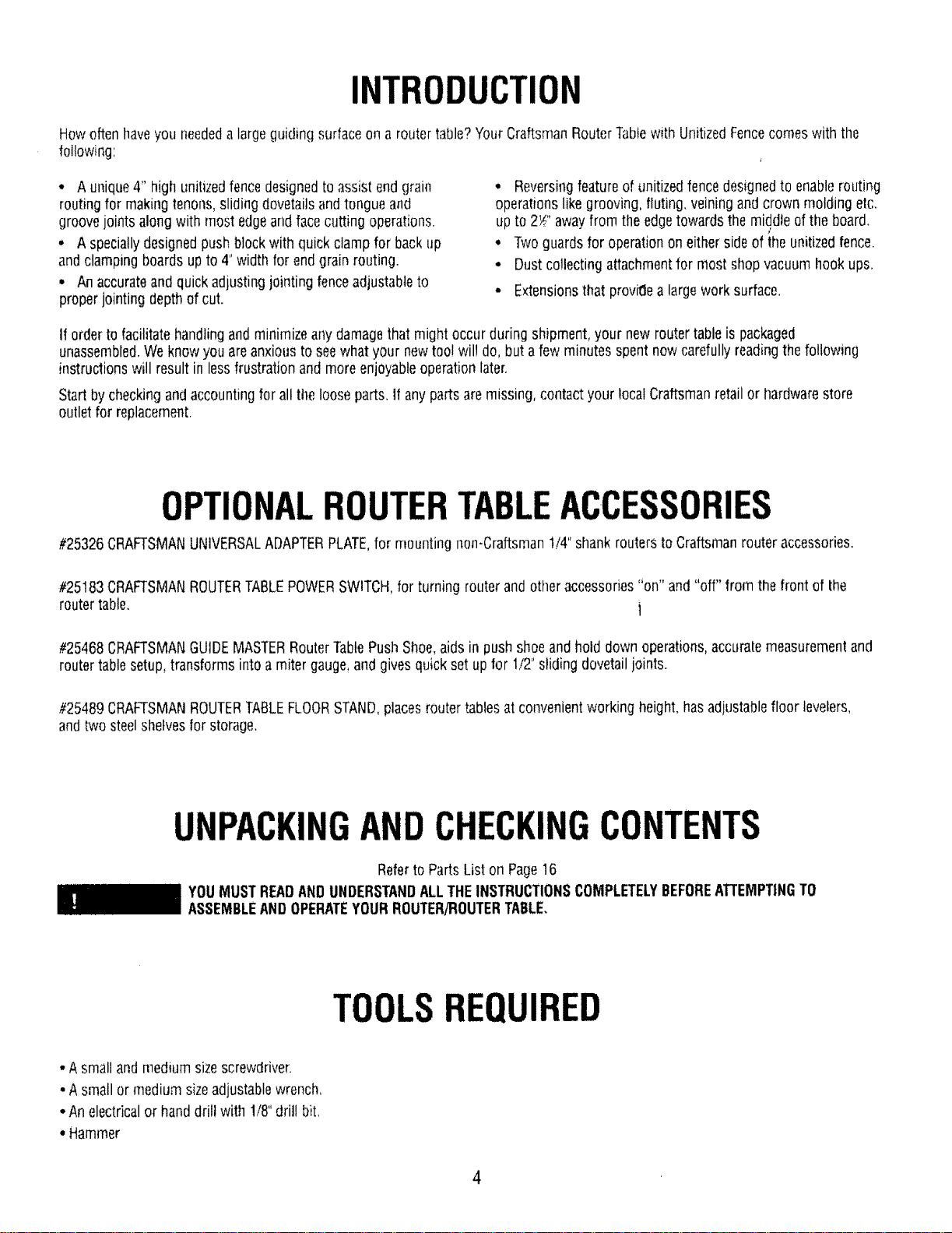
1. Removethe routerbaseplate(back plate)from the router. '
2. Whileholding therouter upsidedown, position it to the
undersidewithin thecenterring of thetabletop, as shown in
Fig.#2,
3. Rotatethe routeruntil thethreemountingholesin the router
baselineup with threeof the holesin thetabletop (It will be
helpfulif you orienttherouter suchthat you caneasilyreachthe
ON/OFFswitch from thefront of thetable.Craftsman_-25183
RouterTableSwitch PackageprovideseasyaccesstoON/OFF
button).
4. Insertthree#!0-32 x _" longflat headmachinescrews
(provided)throughholesin the tabletop (SeeFig,#2) and tighten
securelyinto therouterbase.
FIGURE2
5
SELECTINGANDINSTALLING[ABLEINSERTS
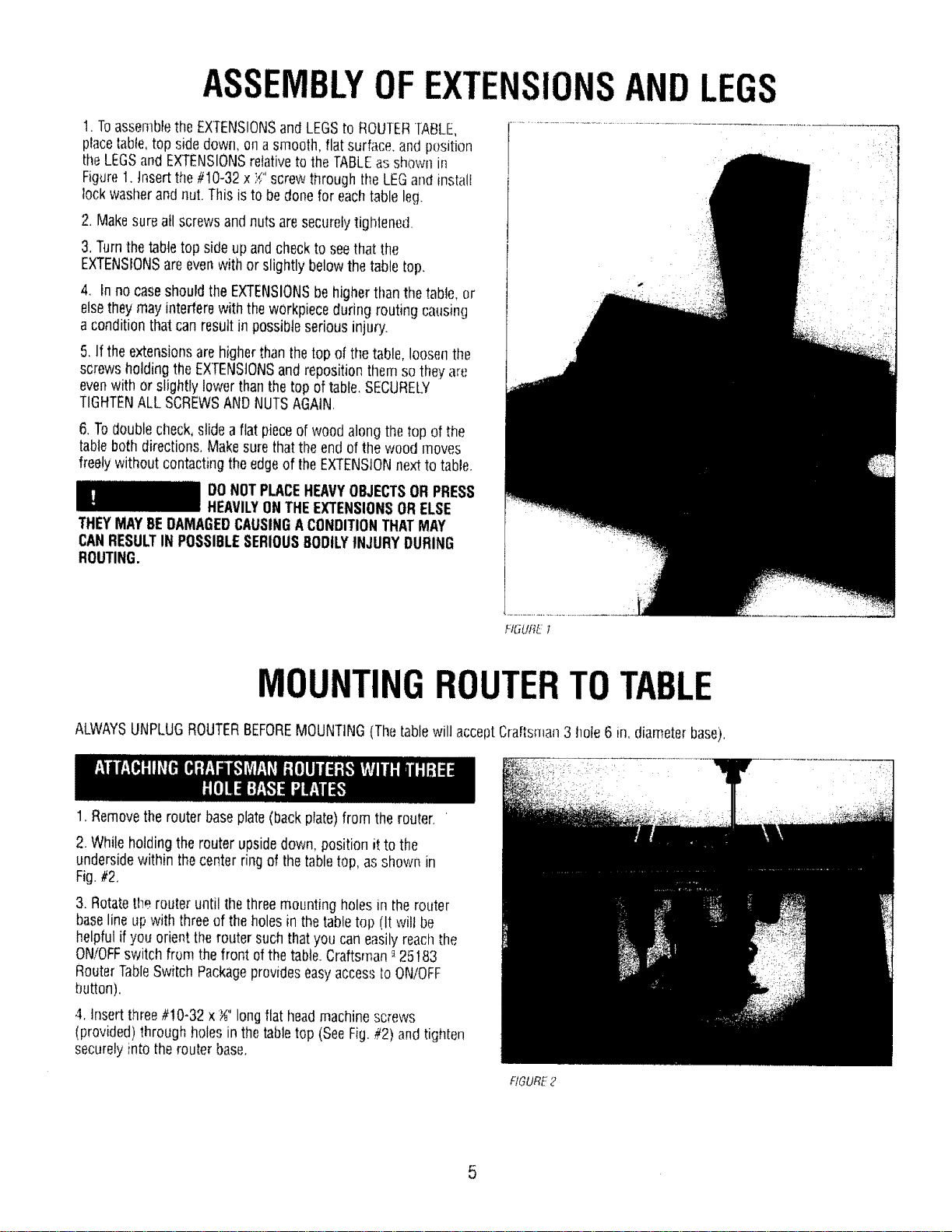
1.With thedesiredbit in the router,selectatable insertwhich hasa
centerholeslightly largerthanthe diameterof therouter [)it.Note:
Forbits largerthanapproximately!_;"diameter,do not usean
insert,
2, Thetableinsertsare designedto besnappedintothe routertable.
Stidethelargetangunder theedgeof thelargeholeinthe router
tableas shownin Fig.#3.Usingyour thumb, pressdown on the
insertuntilthe smalltangsnaps into position
3,Toremovetheinsert,placethebladeof asmall screwdriverinto
theslot (with the smalltang)andprythe insert out of [herouter
table.
BEFOREASSEMBLINGANDATTACHING
UNITIZEDFENCETOTABLE,MAKESURE
THATROUTERISUNPLUGGEDANDTHEBITIS BELOWTHETOP
SURFACEOFTHETABLE.
HGURE3
ASSEMBLYOFUNITIZEDFENCE
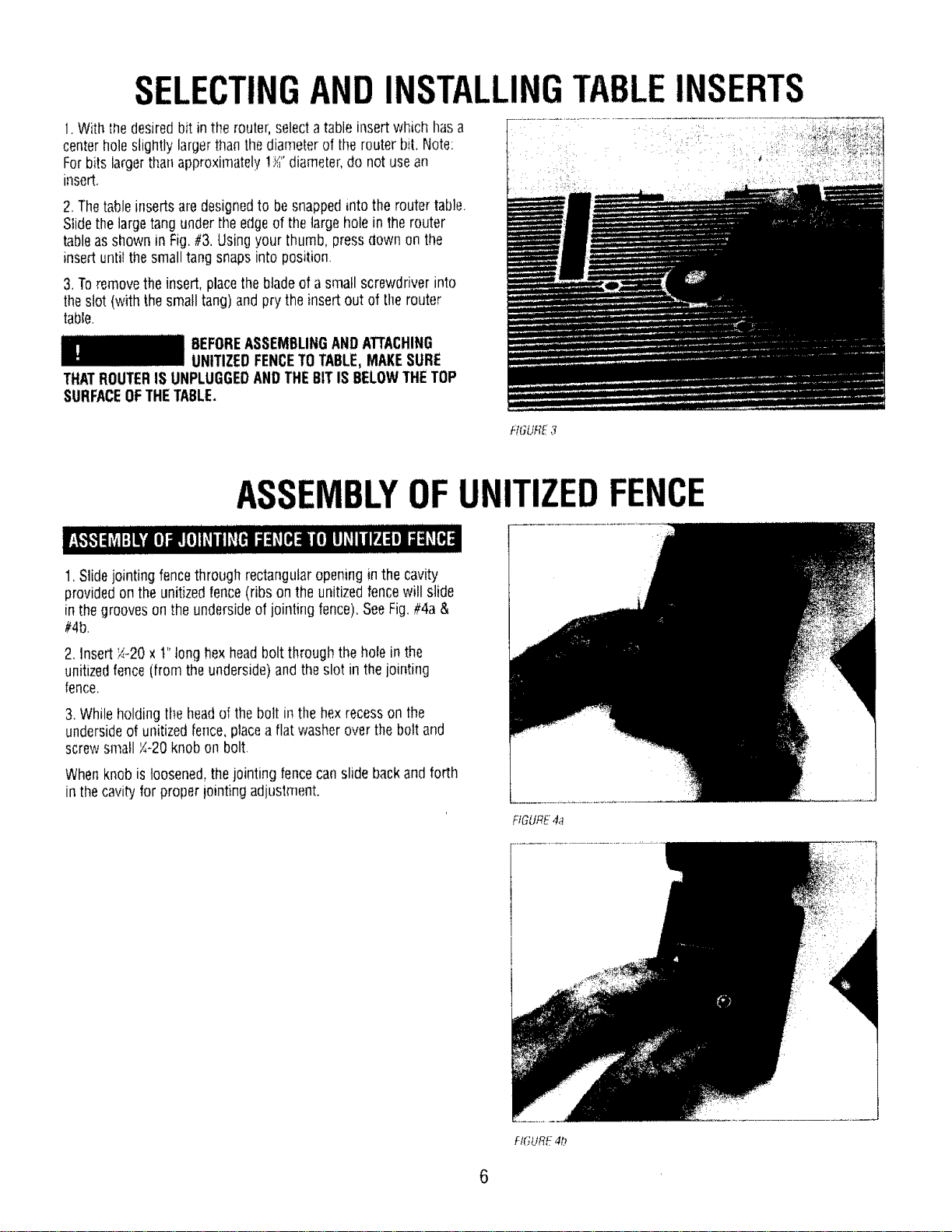
1, Slidejointing fencethrough rectangularopeningin the cavity
providedon the unitizedfence(ribs on the unitizedfencewill slide
in thegroovesonthe undersideof jointingfence).SeeFig.#4a&
#4b.
2, Insert;./.-20x t" tonghexheadboltthrough thehole in the
unitizedfence (from theunderside)and theslot in thejointing
fence,
3.Whileholdingthe headof the bolt inthehex recesson the
undersideof unitized[ence,placea flat washeroverthebolt and
screwsmall _-20 knobon bolt.
Whenknobis loosened,thejointing fencecanslide backand forth
in thecavityfor properiointing adjustment.
FIGURe."4a
FIGURE4b
6
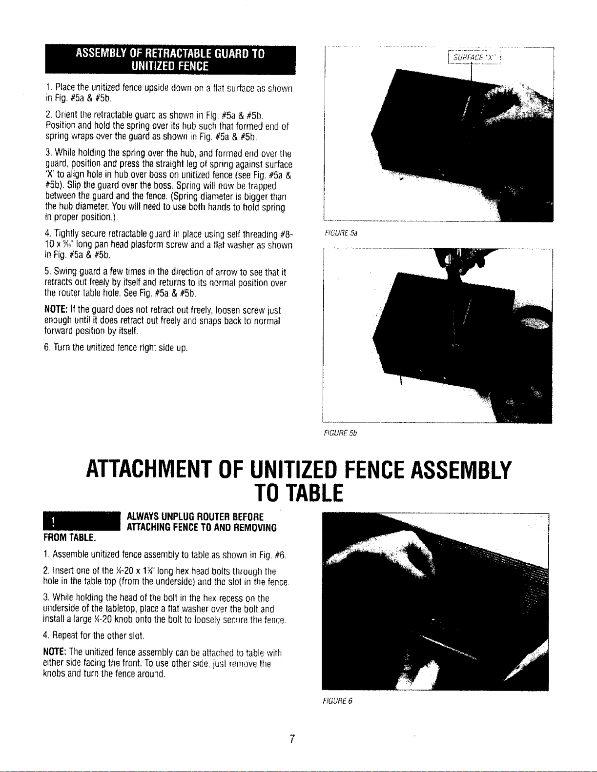
1. Placethe unitizedfenceupsidedownon a flat surfaceasshown
in Fig.#5a&#Sb.
2.Orienttheretractableguardasshown in Fig,#5a & #5b.
Positionand hold the springoverits hub such that formedendof
spring wrapsovertheguardasshown in Fig.#So& #5b.
3. Whileholdingthe springoverthe hub,and formed end overthe
guard,positionandpressthestraight legof springagainstsurface
'X' to align holein hubover bosson unitizedfence(seeFig.#5a &
#5b). Slipthe guardovertheboss,Spring wil! now betrapped
betweenthe guardand thefence.(Spring diameteris biggerthan
thehub diameter.Youwill needto useboth handsto hold spring
in proper position,).
4,Tightlysecureretractableguardin placeusingset!threading#8-
10 x_" longpanheadptasformscrew anda flat washer asshown
in Fig.#5ab,
5, Swingguardafewtimesin the direction of arrowto seethat it
retractsout freelyby itselfandreturnsto its normal positionover
the routertablehole.SeeFig.#5a & #5b.
NOTE:If the guarddoesnot retractout freely,loosenscrewjust
enoughuntil it doesretractoutfreelyand snapsback to normal
forward position by itself,
6.Turnthe unitizedfencerightside up.
f.'K._URE5a
FIGURE5b
ATTACHMENTOFUNITIZEDFENCEASSEMBLY
TOTABLE
FROMTABLE.
ALWAYSUNPLUGROUTERBEFORE
ATTACHINGFENCETOANDREMOVING
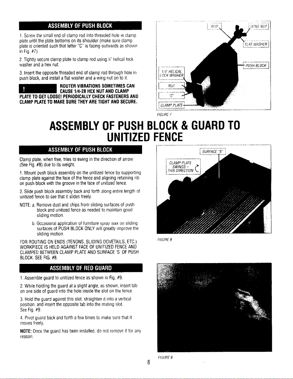
1.Assembleunitizedfenceassemblyto tableas shown in Fig.#6.
2. Insertoneof the_-20 x 1_" long hexheadboltsthroughthe
holein thetabletop (from theunderside)andtheslot in the fence.
3.Whileholding theheadof thebolt in the hexrecesson the
undersideof the tabletop,placea flat washeroverthebolt and
installalarge'_-20knobontothe bolt to looselysecurethefen_:e.
4, Repeatfor tile other slot,
NOTE:Theunitizedfenceassemblycanbe attachedtobible with
eithersidefacingthe front, Touseotherside,justremovethe
knobsandturn the fencearound.
RGURE6
7
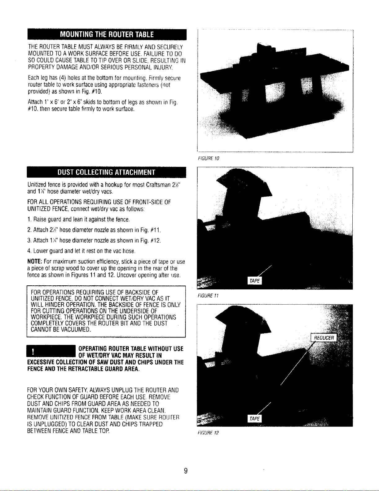
!, Screwthesmall endof clamp rod into threadedhole mclamp
ptateuntilthe platebottoms on its shoulder(makesureclamp
plateisorientedsuch that letter "C" is facingoutwardsas shown
in Fig,//7).
2. Tightlysecureclamp plateto clamprodusing_" helicallock
washerand a hexnut.
3, Inserttheoppositethreadedendof clamprodthrough holein
pushblock,and installa flat washeranda wing nut on to it.
ROUTERVIBRATIONSSOMETIMESCAN
CAUSE1/4-28 HEXNUTANOCLAMP
PLATETOGETLOOSEtPERIODICALLYCHECKFASTENERSAND
CLAMPPLATETOMAKESURETHEYARETIGHTANDSECURE.
, NUT
i[ CLAMPPLATE-
RGURE F
i
'FLAT WASHER
" PUSH BLOCK
ASSEMBLYOF BLOCK& GUARDTO
UNITIZED
Clampplate,whenfree,tries to swing in the directionof arrow
(SeeFig.#8)dueto itsweight.
t. Mount pushblockassemblyon theunitizedfenceby supporting
clampplateagainsttheface ofthefenceand aligning retainingrib
on pushblockwith thegroovein the faceof unitizedfence,
2.Slide pushblockassemblybackand forth alongentirelengthof
unitizedfenceto seethat it slidesfreely.
NOTE:a,Removedustand chips from slidingsurfacesof push
blockandunitizedfenceas neededto maintaingood
slidingmotion.
b,Occasionalapplicationof furniturespray wax on sliding
surfacesof PUSHBLOCKONLYwilt greatly in]provethe
sliding motion,
FORROUTINGONENDS(TENONS,SLIDINGDOVETAILS,ETC,)
WORKPIECEISHELDAGAINSTFACEOFUNITIZEDFENCEAND
CLAMPEDBETWEENCLAMPPLATEANDSURFACE'S'OFPUSH
BLOCK.SEEFIG.#8.
FIGURE8
1.Assembleguardto unitizedfenceasshown in Fig,#9,
2.Whileholdingthe guardat a slight angle,asshown, inserttab
on onesideof guardinto the holeinsidetheslot on the fence.
3,Holdtheguard againstthis slot,straightenit into avertical
position,and insert theoppositetab intothe matingslot.
SeeFig,#9.
4, Pivotguardbackand forth a fewtimes to makesurethat it
movesfreely.
NOTE:Oncetheguard hasbeeninstalled,donol removeit for any
reason,
FIGURE9
8
THEROUTERTABLEMUSTALWAYSBEFIRMLYANDSECURELY
MOUNTEDTOA WORKSURFACEBEFOREUSE.FAILURETODO
SOCOULDCAUSETABLETOTIP OVERORSLIDE,RESUL.TINGIN
PROPERTYDAMAGEANDIORSERIOUSPERSONA[.INJURY,
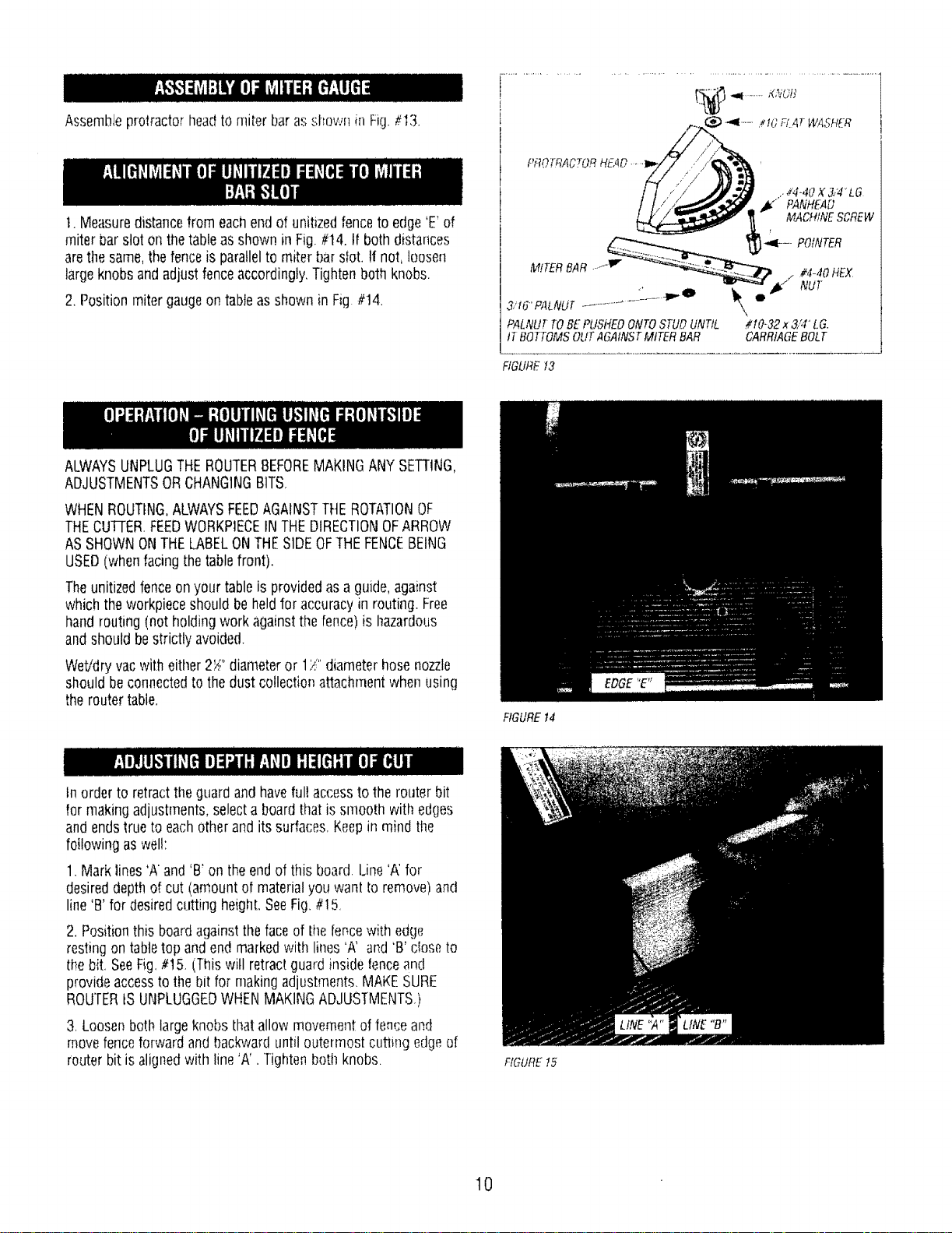
Eachleghas(4} llolesat the bottomfor mounting. Firmlysecure
routertabletowork surfaceusingappropriatefasteneis(not
provided)as shownin Fig,#10.
Attach1"x 6"or 2" x 6"skidsto bottom of legsasshown in Fig.
#10.thensecuretablefirmly to work surface.
FIGUREI0
Unitizedfenceis providedwithahookupfor most Craftsman2_"
and 1¼"hosediameterwet!drj vats.
FORALL OPERATIONSREQUIRINGUSEOFFRONT-SIDEOF
UNITIZEDFENCE,connectwet/dry vacasfollows:
1. Raiseguardandleanit againstthefence,
2. Attach2_" hosediameternozzleas shownin Fig.#'!1.
3.Attach 17"hosediameternozzleas shown in Fig. #12,
4. Lowerguard andlet it rest on thevac hose.
NOTE'.Formaximum suctionefficiency,stick a pieceof tapeor use
a pieceOfscrapwoodto coverupthe openingin therear of the
fenceas shownin Figures1! and 12.Uncoveropeningafter use,
FOROPERATIONSREQUIRINGUSEOFBACKSIDEOF
UNITIZEDFENCE,DONOTCONNECTWET/DRYVACAS IT
WILL HINDEROPERATION,THEBACKSIDEOFFENCE1SONLY
FORCUTTINGOPERATIONSONTHEUNDERSIDEOF
WORKPIECETHEWORKPIECEDURINGSUCHOPERATIONS
COMPLETELYCOVERSTHEROUTERBITAND THEDUST
CANNOTBEVACUUMED.
OPERATINGROUTERTABLEWITHOUTUSE
OFWET/DRYVACMAYRESULTtN
EXCESSIVECOLLECTIONOFSAWDUSTANDCHIPSUNDERTHE
FENCEANDTHERETRACTABLEGUARDAREA,
FORYOUROWNSAFETY,ALWAYSUNPLUGTHE ROUTERAND
CHECKFUNCTIONOFGUARDBEFOREEACHUSE REMOVE
DUSTANDCHIPSFROMGUARDAREAASNEEDEDTO
MAINTAINGUARDFUNCTION,KEEPWORKAREACLEAN.
REMOVEUNITIZEDFENCEFROMTABLE(MAKESUREROUFEr_
tSUNPLUGGED)TOCLEAROUSTANDCHIPSTRAPPED
BElWEENFENCEANDTABLETOE
FIGURE11
FIGURE 12
9
AssembleprotractorheadtOmiter barasshown in Fig.#13.
1.Measuredistancefrom eachendof unitizedfenceto edge'E'of
miter barslot onthetableas shownin Fig.#t4. If both distances
arethe same,thefenceis parallelto miter barsfot. !t not, loosen
largeknobs andadjust fenceaccordingly,Tightenboth knobs.
2.Position miter gaugeon tableas shown in Fig #14.
.._4-417X 3/4 LG
,_" PANHEAD
MACHINESCREW
__"t¢"*......._ -_-- POtNTER
HEX
/
3,'t6'f'ALNUT............... \,
PALNU_TOBE PU,S'HEOONTOSTUDUNTIL #t0-32 x 3,;4"LG.
tT BOTTOMSOUTAGAINSTMtTERBAR CARRtAGEBOLT
FIGURE13
ALWAYSUNPLUGTHEROUTERBEFOREMAKINGANYSETTING,
ADJUSTMENTSORCHANGINGBITS,
WHENROUTING,ALWAYSFEEDAGAINSTTHEROTATIONOF
THECUFrERFEEDWORKPIECEIN THEDIRECTIONOFARROW
AS SHOWNONTHELABELONTHESIDEOFTHEFENCEBEING
USED(whenfacingthetablefront).
Theunitizedfenceon your tableis providedasa guide,against
whichthe workpieceshouldbe heldfor accuracyin routing. Free
handrouting (notholding work againstthe fence)is hazardous
andshouldbestrictly avoided.
Wet/dryvacwith eitller2S" diameteror 1/" diameterhosenozzle
shouldbe connectedtothe dust collectionattachmentwhen using
theroutertable,
FIGUREt4
tn orderto retractthe guardand haveful! accessto the routerbit
for makingadjustments,selecta boardthat is smooth with edges
and endstrueto eachotherand its surfaces,Keepin mind the
foi!owingaswel!:
1.Mark lines'A and'B'on theendof this board.Line'A' for
desireddepthof cut (amount of materialyouwant Io remove)and
line'B' for desiredcutting heighLSeeFig.#I 5,
2. Positionthis boardagainsttheface of tile fencewith edge
restingontabletop and endmarkedwith lines'A' and'B' dose to
the bit. SeeFig,#t5. (Thiswill retractguard insidetenceand
provideaccessto the bit for makingadjustments,MAKESURE
ROUTERtSUNPLUGGEDWHENMAKINGADJUSTMENTS.)
3,Loosenbothlargeknobs thatallow movementoffence and
movefenceforwardand backwarduntil outermostcutting edgeef
routerbit is alignedwith line 'A'. Tightenboth knobs. FfGUREt5
t0
4. Raiseor lowerthe _outeruntil topcutting edg(_cf bd _,.__f!:(m,}d
with line 'B. (Refertoyour routerownel's!rla,llual hji' adjusliq_ I
your routerproper}y).AFTERMAKINGTHISAOJUS:rMENT,i-3E:
SURETHATROUTERISSECURELYTIGHTENEDtN ]HE ROUTER
BASE,BITtS SECURELYTIGHTENEDIN THEROUTEF_CHUCK,
ANDROUTERBASEIS 1tGHTLYSECUREDTOTABLETOK
5, Removethe boardflora thefence,
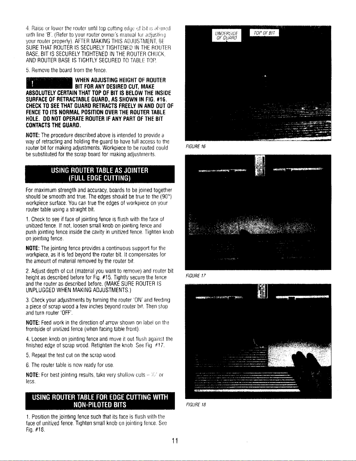
WHENADJUSTINGHEIGHTOFROUTER
BITFORANYDESIREDCUT,MAKE
ABSOLUTELYCERTAINTHATTOPOFBITIS BELOWTHEINSIDE
SURFACEOFRETRACTABLEGUARD,ASSHOWNIN FIG.#16,
CHECKTOSEETHATGUARDRETRACTSFREELYIN ANDOUTOF
FENCETOITS NORMALPOSITIONOVERTHEROUTERTABLE
HOLE, DONOTOPERATEROUTERIF ANYPARTOFTHEBIT
CONTACTSTHEGUARD.
NOTE:Theproceduredescribedaboveis intendedto providea
wayof retractingand holdingthe guard to havefull accessto the
_outerbit for makingadjustment&Workpieceto be routed could
besubstitutedfor thescrap boardfor makingadjustmertts.
Formaximumstrengthandaccuracy,boardsto be joinedtogether
shouldbe smoothandtrue. Theedgesshould be trueto the (90°)
workpiecesurface,You cantruethe edgesof workpieceon your
routertableusinga straightbit.
!, Checkto seeif faceofjointingfence isflush with thefaceof
unitizedfence,If not, loosensmall knobon jointing fenceand
pushjointingfenceinsidethecavity in unitizedfence.Tightenknob
on jointiagfence.
NOTE:Thejointingfenceprovidesa continuoussupport for the
workpiece,asit is fed beyondthe routerbit, tt compensatesfor
theamount of materialremovedbythe routerbit,
2. Adjustdepthof cut (materialyouwant to remove)and routerbit
l]eightas describedbeforefor Fig,#!5, Tightlysecurethefence
andthe routerasdescribedbefore.(MAKESUREROUTERIS
UNPLUGGEDWHENMAKINGADJUSTMENTS.)
3. Checkyour adjustmentsbyturningthe router 'ON'andfeeding
a pieceof scrapwood a few inchesbeyondrouterb_t.Thenstop
andturn router 'OFF',
NOTE:Feedwork in the directionof arrowshown on labelonthe
frontsideof unitizedfence(whenfacingtablefront).
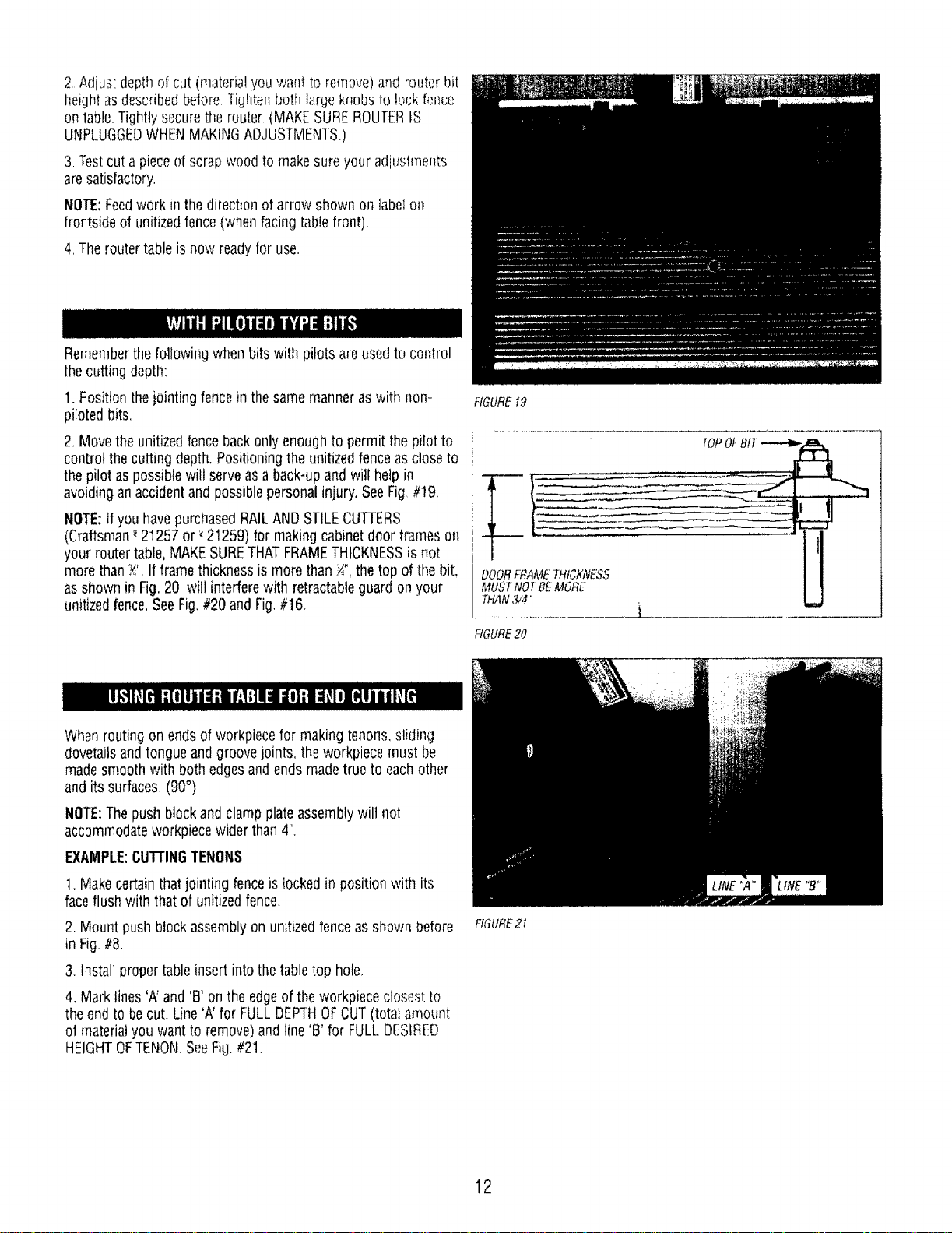
4, Loosenknobon jointing fenceandmove it out flushagainsti:l]e
finishededgeof scrapwood, Retightentheknob SeeFig _17.
5. Repealthetest cut on the scrapwood.
6. Theroutertableis now readyfor use,
NOTE:Forbestjointing results,takevery shallowcuts_--/;:,"or
less.
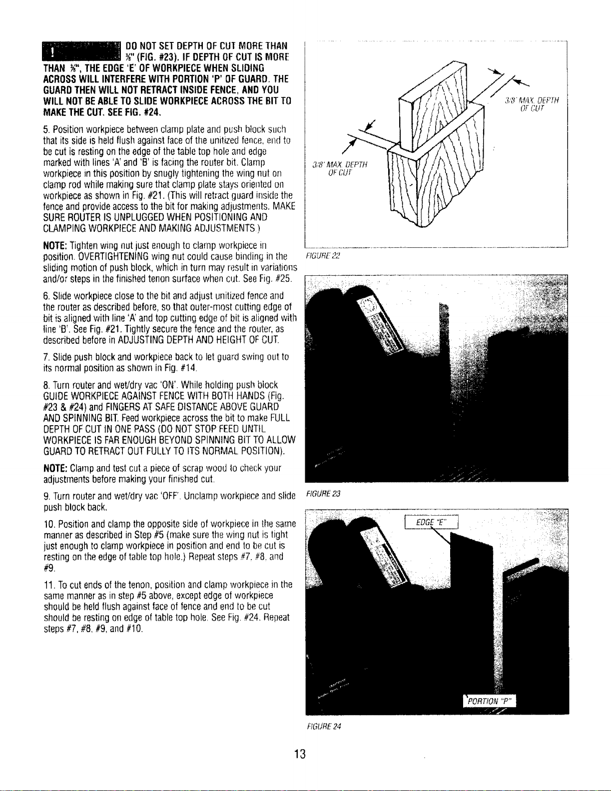
1.Positionthe jointingfence suchthat its faceis flush with the
faceof unitizedfence.Tightensmall knobon jointing fence.See
Fig,#! 8,
fIGUREt6
FIGURE17
RGURE t8
11
2_Adjusldepthof(;ut(materialyouwanttoremove)and routerbit
Ileight asd_,scribedbefore.Tightenboth largeknobs to lock fence
on table.Tightlysecurethe router,(MAKESUREROUTERtS
UNPLUGGEDWHENMAKINGADJUSTMENTS,)
3.Testcut a pieceofscrap woodto makesureyour adjuslments
aresatisfactory.
NOTE:Feedwork in thedirection ofarrow shown on labelon
frontsideof unitizedfence(whenfacing tablefront),
4,Theroutertableis now readyfor use,
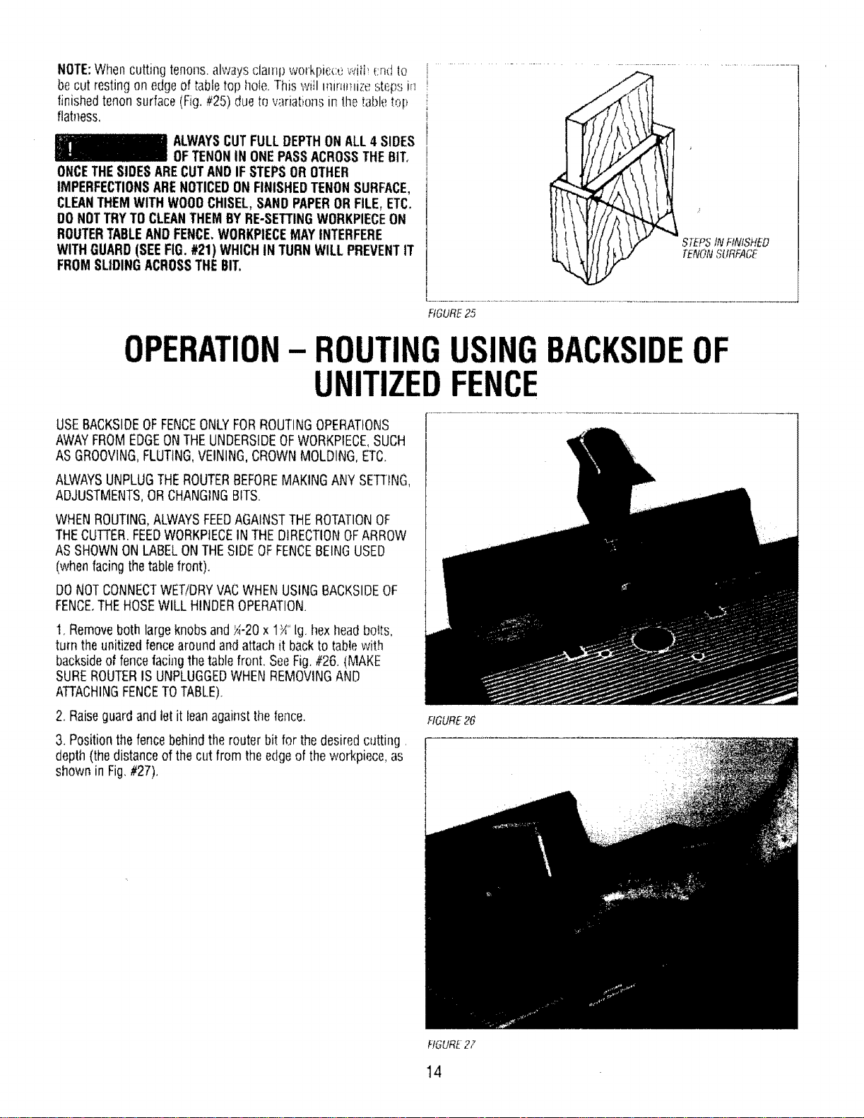
Rememberthefollowing whenbits with pilots are usedto control
thecutting depth:
1. Positionthejointingfencein thesamemanneraswith non-
pilotedbits.
2, Movetheunitizedfencebackonlyenoughto permit thepilot to
controlthe cutting depth.Positioningthe unitizedfenceasclose to
thepilot aspossiblewill serveasa back-upandwill helpin
avoidingan accidentand possiblepersonalinjury,SeeFig.#!9.
NOTE:if you havepurchasedRAILAND STILECUTFERS
(Craftsman-_21257 or _21259) for makingcabinetdoor frameson
your routertable,MAKESURETHATFRAMETHICKNESSis not
morethan_". IIframethicknessis morethan _",thetop of i[f_ebit,
asshown in Fig.20, will interferewith retractableguard onyour
unitizedfence,SeeFig.#20 and Fig.#16,
Whenroutingon endsof workpiecefor making tenons,sliding
dovetailsandtongueandgroovejoints, theworkpiecemust be
madesmoothwith bothedgesandends madetrue to eachother
and its surfaces.(90°)
NOTE:Thepush blockand clampplateassemblywilt not
accommodateworkpiecewiderthan4".
EXAMPLE:CUTTINGTENONS
1.Makecertainthatjointing fenceis lockedin position with its
faceflushwith thatof unitizedfence.
2.Mount push blockassemblyon unitizedfence asshown before
in Fig.#8.
3. Installpropertableinsert intothetabletop hole,
4, Marklines'A' and'B' onthe edgeof theworkpiececlosest to
the endto becut. Line'A' for FULLDEPTHOFCUT(totalamount
of materialyou want to remove)andline 'B' for FULLOEStRED
HEIGHTOFTENON.SeeFig.#2t.
FIGURE_19
THAN3/4"
FIGURE20
[
FfGURE21
12
DONOTSETDEPTHOFCUTMORETHAN
_" (FIG.#23). IF DEPTHOFCUTIS MORE
THAN %",THEEDGE'E' OFWORKPIECEWHENSLIOtNG
ACROSSWILL INTERFEREWITHPORTION'P' OFGUARD.THE
GUARDTHENWILLNOTRETRACTINSIDEFENCE,ANDYOU
WILLNOTBEABLETOSLIDEWORKPIECEACROSSTHEBITTO
MAKETHECUT,SEEFIG.#24.
5. POsitionworkpiecebetweenclampplateandpush block such
that its sideis held flushagainstfaceof the unitizedfence,el_(ito
becut is restingon theedgeof thetabletop hole andedge
markedwithlines'A'and 'B' is facingthe routerbit. Clamp
workpiecein this position by snuglytightening thewing nut on
clamp rod whilemakingsurethatclampplatestays orientedon
workpieceasshownin Fig.#21. (This will retractguard insidethe
fenceandprovideaccessto the bit for makingadjustments.MAKE
SUREROUTERISUNPLUGGEDWHENPOSITIONINGAND
CLAMPINGWORKPIECEANDMAKINGADJUSTMENTS)
NOTE:Tightenwingnut justenoughto clamp workpiecein
position.OVERTIGHTENINGwing nut couldcausebinding in tim
slidingmotion of pushblock,which in turn may resultin variations
andlor stepsin thefinishedtenonsurfacewhencut. SeeFig, #25.
6. Slideworkpiececloseto the bit andadjust unitizedfenceand
therouterasdescribedbefore,sothat outer-most cuttingedgeof
bit is alignedwith line'A'and top cutting edgeof bit is alignedwith
line 'B'. SeeFig,#21.Tightlysecurethefenceand therouter, as
describedbeforein ADJUSTINGDEPTHANDHEIGHTOFCUT.
7. Slidepushblockandworkpiecebackto let guardswingout to
its normal positionasshowninFig.#14.
8.Turnrouterand wet/dryvac 'ON'.Whileholding push biock
GUIDEWORKPIECEAGAINSTFENCEWITH BOTHHANDS(Fig.
#23 & #24) and FINGERSATSAFEDISTANCEABOVEGUARD
ANDSPINNINGBIT.Feedworkpieceacrossthe bit to makeFULL
DEPTHOFCUTtN ONEPASS(DONOTSTOPFEEDUNTIL
WORKPIECEISFARENOUGHBEYONDSPINNINGBITTOALLOW
GUARDTORETRACTOUTFULLYTOITSNORMALPOSITION).
NOTE:Clampand testcut a pieceof scrapwood Io ci:leckyour
adjustmentsbeforemakingyour finishedcut.
9. Turnrouterand wet/dry vac 'OFF'.Unclampworkpieceand slide
pushblockback,
10.PositionandclamptheoppositeskJeof workpiecein tile same
mannerasdescribedin Step#5 (makesurethe wing nut istight
just enoughto clamp workpiecein position and end to becut is
restingontheedgeoftabletop hole.} Repeatslops#7. #8,and
#9.
11,Tocut endsof thetenon, positionand clamp workpiecein the
samemanrmrasinstep#5 above,exceptedgeof workpiece
shouldbe hetdflush againstfaceof fenceandendtobecut
shouldbe restingonedgeoftabletop hole,SeeFig.#24, Repeat
steps#7, #8,#9, and#10.
• " ' " , 3,"8' MAX.DEPTH
f
3,'8"&'lAX.DEPTH
o_-CUr
FIGURE22
HGURE23
EDGE"E"
_ i ¸ i :' ¸¸ ?
#IGURE24
13
NOTE:Whencutting tenons,alwaysclamp work[)ic(:_,_,_.Ati,(:ndto
becutrestingon edgeof tabletop hote,1his will inmnuizeste_sm
finishedtenor]surface(Fig.#25) dueto w.triationsin lhe tabletop
flatness,
ALWAYSCUTFULLDEPTHONALL4 SIDES
OFTENONIN ONEPASSACROSSTHE6IT,
ONCETHESIDESARECUTANDIF STEPSOROTHER
IMPERFECTIONSARENOTICEDONFINISHEDTENONSURFACE,
CLEANTHEMWITHWOO0CHISEL,SANDPAPERORFILE,ETC.
DONOTTRYTOCLEANTHEMBYRE-SETTINGWORKPIECEON
ROUTERTABLEANDFENCE,WORKPIECEMAYINTERFERE
WITHGUARD(SEEFIG.#21) WHICHiN TURNWILLPREVENTIT
FROMSLIDINGACROSSTHEBIT.
STEPStNFINISHED
TENONSURFACE
FIGURE25
OPERATION
ROUTINGUSINGBACKSIDEOF
UNITIZEDFENCE
USEBACKSIDEOFFENCEONLYFORROUTINGOPERATIONS
AWAYFROMEDGEONTHEUNDERSIDEOFWORKPIECE,SUCH
AS GROOVING,FLUTING,VEINING,CROWNMOLDING,ETC,
ALWAYSUNPLUGTHEROUTERBEFOREMAKINGANYSETTING,
ADJUSTMENTS,ORCHANGINGBITS.
WHENROUTING,ALWAYSFEEDAGAINSTTHEROTATIONOF
THECUTi'ER.FEEDWORKPtECEINTHEDIRECTIONOFARROW
ASSHOWNONLABELONTHESIDEOFFENCEBEINGUSED
(whenfacingthetablefront),
DONOTCONNECTWET/DRYVACWHENUSINGBACKSIDEOF
FENCE,THEHOSEWILL HINDEROPERATION.
t. Removeboth largeknobsandk._-20x 1_"lg. hexheadbotts,
turn theunitizedfence aroundandattachit backto tablewith
backsideof fencefacingthetablefront. SeeFig.#26. (MAKE
SUREROUTERISUNPLUGGEDWHENREMOVINGAND
ATTACHINGFENCETOTABLE).
2. Raiseguardandlet it leanagainst,thefence.
3. Positionthefencebehindthe routerbit for the desiredcutting.
depth(thedistanceof thecut from theedgeof the workpiece,as
shown in Fig.#27).
FIGURE26
FIGURE27
14
4. S(;cureivllgh!(!n br}thkn(}b::_andi i)WER ll-fi} f_lJ_&iq_:_,_');.;_:t:_
THEBIT
5. Make,die cut fly sli(lmg,shai[,hi _,,_I!j-;_'o! wo_kpiecea:lamStt!]e
fence.(Foreachsucc_ssve cut,thefencewould needto bc
readjtJsted.)
NOTE:Testcol a pieceof scrapwood beforemakingyotir finish(!d
cut. Feedworkpiecein the directiond arrow shownon _er_c__,label
(Fig.//28).
NOTE:Whenrouting deepcuts(conboiled byrouter bit) in a
workpie(,e,removematerialin incrementsto preventyour router
from overloading.Repeatoperationwith severalpassesuntil the
desireddepthisachieved.
F!GLIR_28
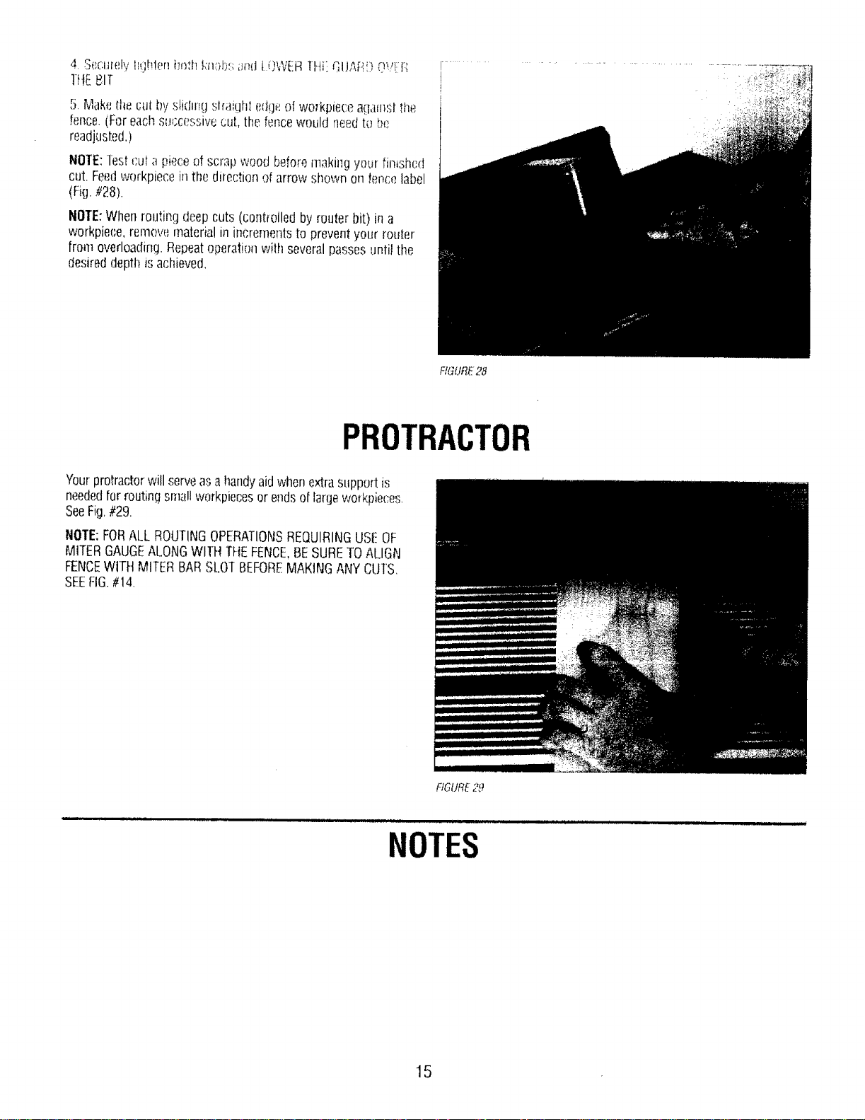
PROTRACTOR
Yourprotractorwillserveasa !landyaidwhenextrasupportis
neededforroutingsmallworkpiecesor endsoi'largeworkpiec:e,s.
SeeFig.#29.
NOTE:FORALL ROUTINGOPERATIONSREQUIRINGUSI!:OF
MITERGAUGEALONGWITHTHEFENCE.BESURETOALIGN
FENCEwrrH MITERBARSLOTBEFOREMAKINGANYCU]S
SEEFIG.#14,
FIGURE29
NOTES
15
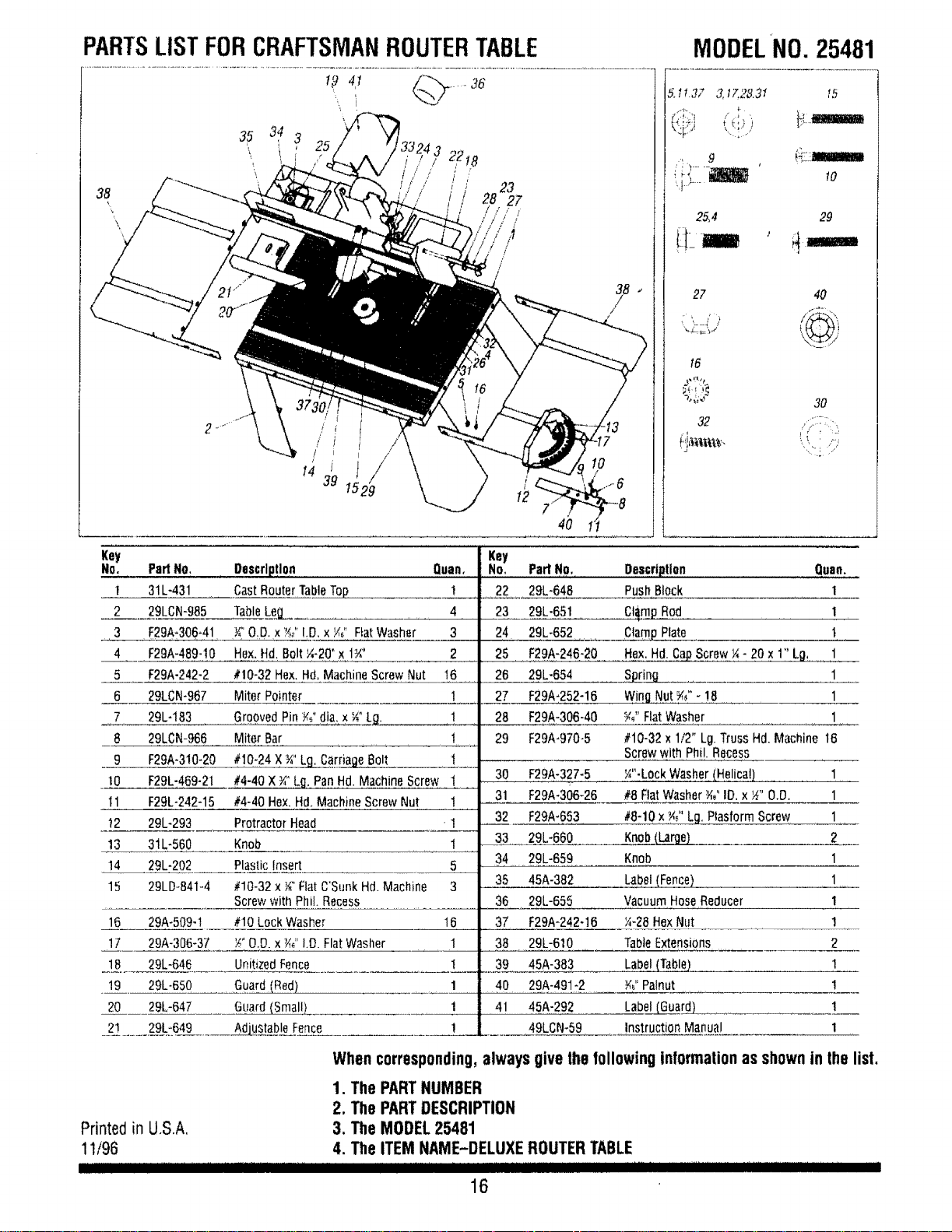
PARTSLISTFORCRAFTSMANROUTERTABLE
! -_ 4t _'_.._ ..... 36
Key
No. PartNO,
! 31L-431
2 29LCN-985
3 F29A*306-41
4 F29A-489-10
5 F29A-242-2
6 2gLeN-967
7 29L-183
8 29LCN-966
9 F29A-310-20
tO F29L-469-21
I1 F29L-242-15
t2 29L-293
13 31L-560
14 29L-202
15 29LDo841-4
16 29A-509-1
17 29A-306-37
18 29L-645
19 29L-650
20 29L-647
2_ ...... 2__:6_9._....... AAdjustableFence
t
,/
J
14 39
/
/
/
29
Description Quan,
CastRouterTableTop 1
TableLeg_ 4
Y_"O.D.x ?d'!O, x/,_" FiatWasher 3
Hex.Hd,Bolt ¼-2(Yx I:Y,' 2
#10-32Hex.Hd,MachineScrewNut 16
Miter Pointer 1
GroovedPinY¢ dia,x _"_LL_
Miter Bar 1
#!0-24 X¾"Lg_CarnageBolt t
#4-40x ¾"Lfl, PanHd. MachineScrew !
#4-40Hex.Hd.MachineScrewNut 1
ProtractorHead ' 1
Knob 1
PlasticInsert 5
#!0-32 x _" FlatC'SunkHd. Machine 3
Screwwith Phil.Recess
#10LockWasher 16
_" O,D.x _" I.O.FlatWasher 1
UnitizedFence I
Guard(Red) 1
Guard(Small) 1
Key
No,
22
23
24
25
26
27
28
29
MODELNO.25481
5.I .3_ 3,t7.28.31 lb
'_,_-h ' {t[Lt&WaIIIiMB
25,4 29
27 40
t6
-';'i;'_ 30
J [ " :__
Parl No. Oescrtlltlon Quan.
29L-648 PushBlock 1
29L-65t Ct_m£Rod 1
29L-652 C]am_Plate t
F29A-246-20 Hex.Hd.CaPScrew¼- 20 x 1" Lg, 1
29L-654 Spring 1
F29A-252-16 Wing.Nut _" - ! 8 ....... 1
F29A-306-40 W' FlatWasher 1
F29A-970-5 #10-32x 1/2" Lg.TrussHd. Machine t6
Screwwith Phi!.Recess
30 F29A-327-5 _"-LockWasher(He!ica!) 1
31 F29A-306-26 #8 FlatWasher¾_"IO.x _" 0.0. 1
32 F29A-653 #8-10x _" Lg. PlasformScrew 1
33 29L-660 Knob£Lar__ 2
34 29L-659 Knob 1
35 45A-382 Label(Fence) 1
36 29L-655 VacuumHoseReducer 1
37 F29A-242-16 _4-28HexNut 1
38 29L-610 TableExtensions 2
39 45A-383 Label(Table_]. 1
40 29A-491*2 Y,"Palnut !
41 45A-292 Label6___.uard__ 1
49LCN-59 instructionManual 1
Printed in U.S.A,
11/96
I]1111!11 ........
Whencorresponding,alwaysgivethefollowing informalionas shownin thelist.
1. The PARTNUMBER
2. The PARTDESCRIPTION
3. The MODEL 25481
4. The ITEM NAME-DELUXE ROUTER TABLE
16