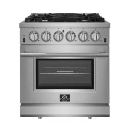
FREESTANDING GAS RANGE
5015011
Conforms to ANSI STD Z21.1-2018 Certified to CSA STD 1.1-2018 Household Cooking Gas Appliances.
INSTALLATION GUIDE
SPECIFICATIONS, INSTALLATION, AND MORE
MODEL NUMBERS:
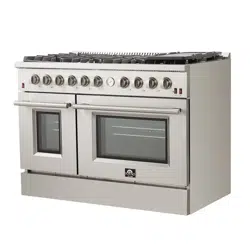
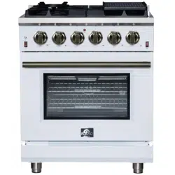
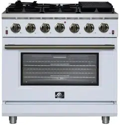
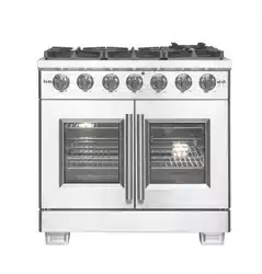
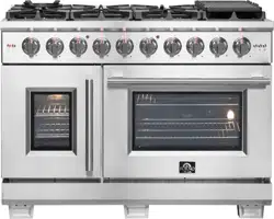
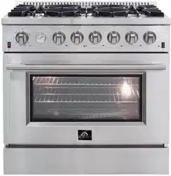
FFSGS6291-30 FFSGS6291-36 FFSGS6291-48
Index
Customer care 1
Consumer information 2
Anti-tip Device 2
Important Safety information 3
Features of your range 6
Installation instructions 7
Door Handle Installation 8
Surface Burner Grills Installation 8
Oven Rack Installation 9
Electrical 9
Gas Supply 10
Product Dimensions and Cabinets 11
Exhaust Hood Installation 12
Gas Conversion Operation 13
Gas Supply Connection 18
Surface Burner Operation 18
Oven Operation 20
Care and Maintenance recommendations 22
Troubleshooting tips 22
Wire Diagram 24

1
Customer Care
Thank you for purchasing a FORNO product. Please read the entire instruction manual before operating your new
appliance for the first time. Whether you are an occasional user or an expert, it will be beneficial to familiarize
yourself with the safety practices, features, operation and care recommendations of your appliance.
Both the model and serial number are listed in the left corner of the door. For warranty purposes, you will also need
the date of purchase. Record this information below for future reference.
SERVICE INFORMATION
Model Number: Use these numbers in any correspondence or
service calls concerning your cooking range.
Serial Number: If you received a damaged appliance, immediately
contact the dealer (or builder) that sold you the
product.
Date of Purchase:
Purchase Address & Phone: Save time and money. Before you call for service,
check the Troubleshooting Guide. It lists the causes
of minor operating problems that you can correct
yourself.
SERVICE IN CANADA:
Keep the instruction manual handy to answer your questions. If you don’t understand something or you need more
assistance, please call our Customer Service: 1-866-231-8893
Or contact: CTM Househould Appliances Inc
11420 Albert Hudon, Montreal, Quebec, H1G 3J6, Canada
SERVICE IN THE UNITED STATES:
Keep the instruction manual handy to answer your questions. If you don’t understand something or you need more
assistance, please call our Customer Service: 1-866-231-8893
The instruction manual can be downloaded from www.forno.ca
If your appliance ever requires servicing, be sure to use a FORNO Factory Certified Service provider
recommended by our customer care center. All Factory Certified Service providers are carefully selected and
thoroughly trained by us.
2
Consumer information
Range Safety
Your safety and the safety of others are very important.
We have provided many important safety messages in this manual and on your appliance. Always read and obey
all safety messages.
This is a safety alert symbol. It will alert you to potential personal or property safety hazards. Obey all
safety messages to avoid any property damage, personal injury or death.
WARNING
WARNING indicates a potentially hazardous situation which, if not avoided, could result
in serious injury or death.
CAUTION
CAUTION
indicates a moderate hazardous situation which, if not avoided, could result in
minor or moderate injury.
All safety messages will alert you what the potential hazard is, tell you how to reduce the
chance of injury, and let you know what can happen if the instructions are not followed.
WARNING
If the information in this manual is not followed exactly, a fire or explosion may result,
causing property damage, personal injury or death.
Do not store or use gasoline or other flammable vapors and liquids in the vicinity of this or
any other appliance.
- WHAT TO DO IF YOU SMELL GAS
• Do not try to light any appliance.
• Do not touch any electrical switch.
• Do not use any phone in your building.
• Immediately call your gas supplier from a neighbor’s phone. Follow the gas supplier’s instructions.
• If you cannot reach your gas supplier, call the fire department.
Installation and service must be performed by a qualified installer, service agency or the gas supplier.
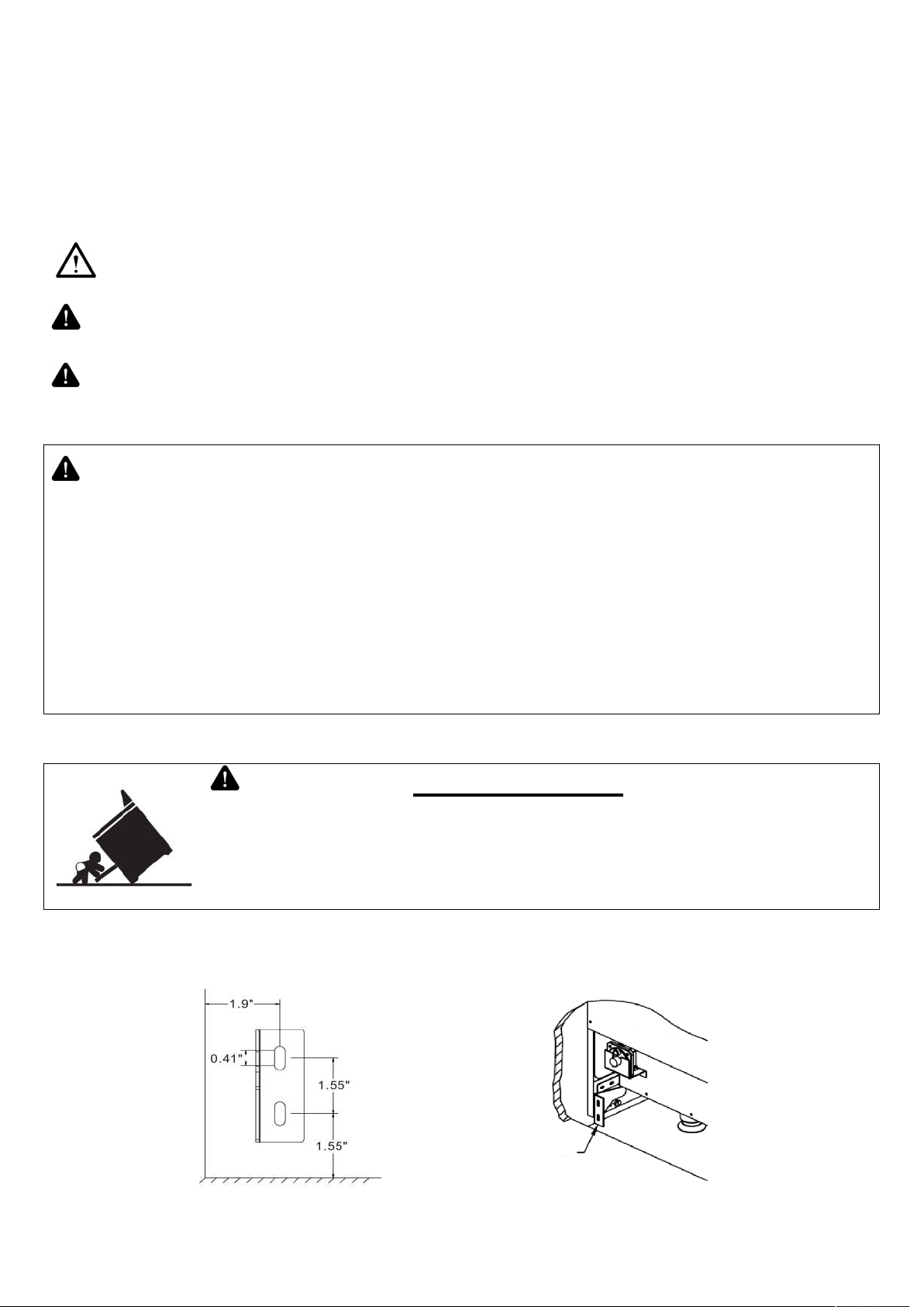
ANTI-TIP DEVICE
WARNING
Tip-over Hazard
A Child or adult can tip the range which can result in serious injuries or death.
Install the anti-tip device to the range and/or structure per installation instructions.
Engage the range to the Anti-tip device installed to the structure.
Re-engage the anti-tip device if the range is removed.
Failure to follow these instructions can result in death or serious injuries and/or burns to
children and adults.
To reduce the risk of tipping the range, the range must be secured by properly installed anti-tip device packed with
the range. All ranges can tip and cause injuries.
Make sure the anti-tip bracket is installed.
Anti-tip bracket
Range back panel

3
1) Find the anti-tip bracket and screws from the accessories bag.
2) Drill 2 holes on the wall according the above drawing.
3) Fix the anti-tip bracket securely to the wall.
4) Slide in the cooking range towards the anti-tip bracket. Check to make sure it is properly installed.
WARNING
This product can expose you to chemicals including carbon monoxide, which is known to
the State of California to cause developmental harm. For more information go to
www.P65Warnings.ca.gov.
To minimize exposure to these substances. Always operate this unit according the Instruction Manual, and ensure
that you provide proper ventilation.
The installation must conform with local codes or, in the absence of local codes, with the National Fuel Gas Code,
ANSI Z223.1/NFPA 54 or, in Canada, the Natural Gas and Propane Installation Code, CSA B149.1.
WARNING
Never operate the top surface cooking section of the appliance unattended. Failure
to follow this warning statement may result in fire, explosion or burn hazard that
could cause property damage, personal injury or death. If a fire should occur, keep
away from the appliance and immediately call your fire department.
DO NOT ATTEMPT TO EXTINGUISH AN OIL/GREASE FIRE WITH WATER.
IMPORTANT SAFETY INFORMATION
READ ALL INSTRUCTIONS BEFORE USING THE APPLIANCE
WARNING
Read all safety instructions before using the product. Failure to follow these instructions
may result in fire, electrical shock, serious injury or death。
GENERAL SAFETY INSTRUCTIONS
WARNING
NEVER use this appliance as a space heater to heat or warm the room. Doing so
may result in carbon monoxide poisoning and overheating of the oven.
1. Use this range for its intended purpose as described in this instruction manual.
2. Have your range installed and properly grounded by a qualified installer in accordance with the provided
installation instructions.
3. Any adjustment and service should be performed only by a qualified gas range installer or service technician. Do
not attempt to repair or replace any part of your range unless it is specifically recommended in this manual.
4. Your range is shipped from the factory set for use with natural gas or propane (LP) gas. It can be converted for
use with either. If required, these adjustments must be made by a qualified technician in accordance with the
installation instructions and local codes. The agency performing this work assumes responsibility for the
conversion.
5. Have the installer show you the location of the range gas shut-off valve and how to turn it off if necessary.
6. Plug your range into a 120-volt grounded outlet only. Do not removed the round grounding prong from the plug.
If in doubt about the grounding of the home electrical system, it is your responsibility and obligation to have an
ungrounded outlet in accordance with the National Electrical Code. Do not use an extension code with this range.
7. Before performing any service, unplug the range or disconnect the power supply at the household distribution
panel by removing the fuse or switching off the circuit breaker.
8. Be sure all packing materials are removed from the range before operating to prevent ignition of these materials.
9. Avoid scratching or impacting glass displays. Doing so may lead to glass breakage. Do not cook on a product
with broken glass. Shock, fire, or cuts may occur.
10. Do not leave children alone or unattended in an area where an appliance is in use. They should never be
allowed to climb, sit or stand on any part of the range.
11.
CAUTION
Do not store items of interest to children in cabinets above an oven-children who climb
onto the oven to reach items could be seriously injured.
12. Never block the vents (air openings) of the range. They provide the air inlets and outlets that are necessary for
the range to operate properly with correct combustion. Air openings are located at the rear of the cooktop, at the
top and bottom of the oven door, and at the bottom of the range.
13. Use only dry pot holders--moist or damp pot holders on hot surfaces may result in burns from steam. Do not let
pot holders touch surface burners, burner grate, or oven heating element. Do not use a towel or other bulky fabrics
4
in place of pot holders.
14. Do not touch the heating elements or the interior surface of the oven. These surfaces may be hot enough to
burn even though they are dark in color. During and after use, do not touch, or let clothing or other flammable
materials contact any interior area of the oven; allow sufficient time for cooling first. Other surfaces of the appliance
may become hot enough to cause burns. Potentially hot surfaces include the burners, grates, oven vent opening,
surfaces near the opening, crevices around the oven door, metal trim parts above the door, any back guard, or
high shelf surface.
15. Do not heat unopened food containers. Pressure could build up and the container could burst, causing any
injury.
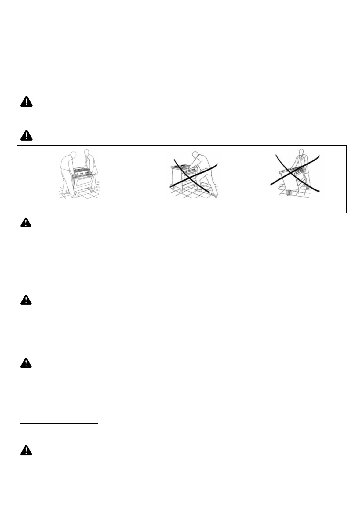
WARNING
Extremely Heavy.
Proper equipment and adequate manpower are needed when move the range to avoid personal injury or damage
to the unit or the floor. Failure to follow this advice may result in damage or personal injury.
WARNING
DO NOT carry or lift the cooking range by the oven door handle or the control panel!
CORRECT INCORRECT
WARNING
GENERAL SAFETY INSTRUCTIONS
Cook food thoroughly to help protect against foodborne illness. Minimum safe food temperature recommendations
can be found at www.IsItDoneYet.gov and www.fsis.usda.gov. Use a food thermometer to take food temperatures
and check several locations.
Do not allow anyone to climb, stand or hang on the oven door, drawer or cooktop. They could damage the range or
tip it over causing severe injury or death.
Keep the ventilator hood and grease filter clean to maintain good venting and to avoid grease fires. Turn the
ventilator OFF in case of a fire or when intentionally "flaming" liquor or other spirits on the cooktop. The blower if in
operation, could spread the flames.
WARNING
KEEP FLAMMABLE MATERIAL AWAY FROM THE RANGE
Failure to do so may result in fire or personal injury.
Do not store or use flammable materials in an oven or near the cooktop, including paper, plastic, pot holders,
linens, wall coverings, curtains, drapes and gasoline or other flammable vapors and liquids.
Never wear loose-fitting or hanging garments while using the appliance. These garments may ignite if they contact
hot surfaces causing severe burns.
Do not let cooking grease or other flammable materials accumulate in or near the range.
Grease in the oven or on the cooktop may ignite.
WARNING
IN THE EVENT OF A FIRE, TAKE THE FOLLOWING STEP TO PREVENT
INJURY AND FIRE SPREADING.
Do not use water on grease fires. Never pick up a flaming pan. Turn the controls off. Smother a flaming pan on a
surface unit by covering the pan completely with a well-fitting lid, cookie sheet or flat tray. Use a multi-purpose dry
chemical or foam-type fire extinguisher.
If there is a fire in the oven during baking, smother the fire by closing the oven door and turning the oven off or by
using a multi-purpose dry chemical or foam-type fire extinguisher.
If there is a fire in the oven during self-clean, turn the oven off and wait for the fire to go out.
Do not force the door open. Introduction of fresh air at self-clean temperatures may lead to a burst of flame from
the oven. Failure to follow this instruction may result in severe burns.
WARNING
COOKTOP SAFETY INSTRUCTIONS
Never leave the surface burners unattended at medium or high heat settings. Foods, especially oily foods, may
ignite resulting in fire that could spread to surrounding cabinets.

5
Never leave oil unattended while frying. If allowed to heat beyond its smoking point, oil may ignite resulting in fire
that may spread to surrounding cabinets. Use a deep fat thermometer whenever possible to monitor oil
temperature.
To avoid oil spillover and fire, use the minimum amount of oil when frying in a shallow pan and avoid cooking
frozen foods with excessive amounts of ice.
Use proper pan size and avoid pans that are unstable or easily tipped. Select cookware that matches the size of
the burner. Burner flames should be adjusted so that they do not extend beyond the bottom of the pan. Excessive
flames may be hazardous.
When using glass/ceramic cookware, make sure it is suitable for cooktop use; others may break because of a
sudden change in temperature.
To minimize the possibility of burns, ignition of flammable materials and spillage, cookware handles should be
turned toward the center of the range without extending over nearby burners.
Do not use a wok with a round metal support ring. The ring may trap heat and block air to the burner resulting in a
carbon monoxide hazard.
Do not attempt to lift the cooktop. Doing so may damage the gas tubing to the surface burners resulting in a gas
leak and risk of fire.
Do not use aluminum foil to cover the grills or line any part of the cooktop. Doing so may result in carbon monoxide
poisoning, overheating of the cooktop surfaces, or a potential fire hazard.
WARNING
OVEN SAFETY INSTRUCTIONS
NEVER cover any slots, holes, or passages in the oven bottom or cover an entire rack with materials such as
aluminum foil or oven liners. Doing so blocks air flow through the oven and may cause carbon monoxide poisoning.
Never place foil or oven liners on the oven bottom. They can trap heat causing risk of smoke or fire.
Stand away from the range when opening the oven door. Escaping hot air or steam can cause burns to hands,
face and/or eyes.
Never place cooking utensils, pizza or baking stones, or any type of foil or liner on the oven floor.
These items can trap heat or melt, resulting in damage to the product and risk of shock, smoke or fire.
Place oven racks in desired location while oven is cool. If the rack must be moved while the oven is hot, be careful
to avoid touching hot surfaces.
Do not leave items such as paper, cooking utensils, or food in the oven when not in use. Items stored in an oven
can ignite.
Do not leave items on the cooktop near the oven vent. Items may overheat resulting in a risk of fire or burns.
Never broil with the door open. Open-door broiling is not advised due to overheating of control knobs.
6
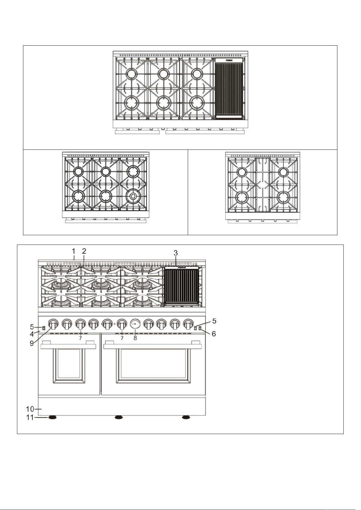
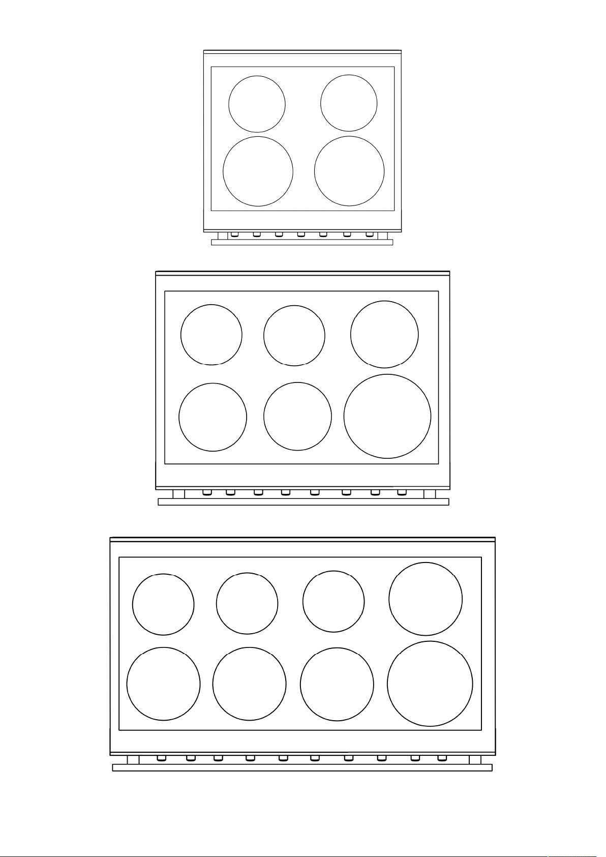
Features of Your Range
8 burners (FFSGS6291-48)
6 burners (FFSGS6291-36) 4 burners (FFSGS6291-30)
Not all features are on all models. Appearance may vary.
1. Oven Vents
2. Surface Burner Grates
3.
Griddle (for FFSGS6291-48 only)
4.
Control panel
5.
Oven light switch
6.
Convection Fan switch
7.
Oven/broil burner control knob
8.
Temperature gauge
9.
Surface burner control knob
10.
Kick Panel
11.
Leveling System(Oven legs)
7
INSTALLATION INSTRUCTIONS
Before using your range
1. Remove all packaging material.
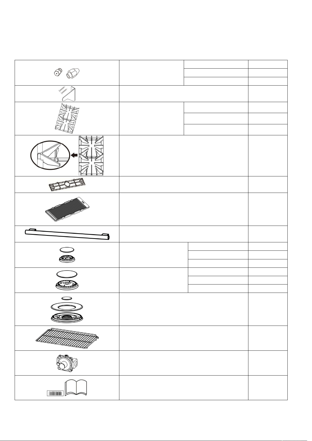
2. Check to make sure you have all of the accessories listed below
LPG injector
FFSGS6291-30 6 sets
FFSGS6291-36 10 sets
FFSGS6291-48 13 sets
Anti-tip bracket and screws 1 set
Burner grills
FFSGS6291-30 2 pieces
FFSGS6291-36 3 pieces
FFSGS6291-48 3 pieces
Burner grill
(for FFSGS6291-48 only)
1 piece
Burner grill (for FFSGS6291-30 only 1 piece
Cook plate (Griddle)
(*for FFSGS6291-48 only)
1 piece
Oven door handle
(* 2pcs for FFSGS6291-48)
1 piece
Burner & Cap
(9000BTU)
FFSGS6291-30 2 sets
FFSGS6291-36 2 sets
FFSGS6291-48 3 sets
Burner & Cap
(15000BTU)
FFSGS6291-30 2 sets
FFSGS6291-36 3 sets
FFSGS6291-48 4 sets
Burner & Cap
(20000BTU)
(*for FFSGS6291-36 & FFSGS6291-48 only)
1set
Baking rack
(*4 pcs for FFSGS6291-48)
2 pieces
Regulator (pre-installed) 1 piece
Serial Number Sticker & Instruction Manual 1 set
8
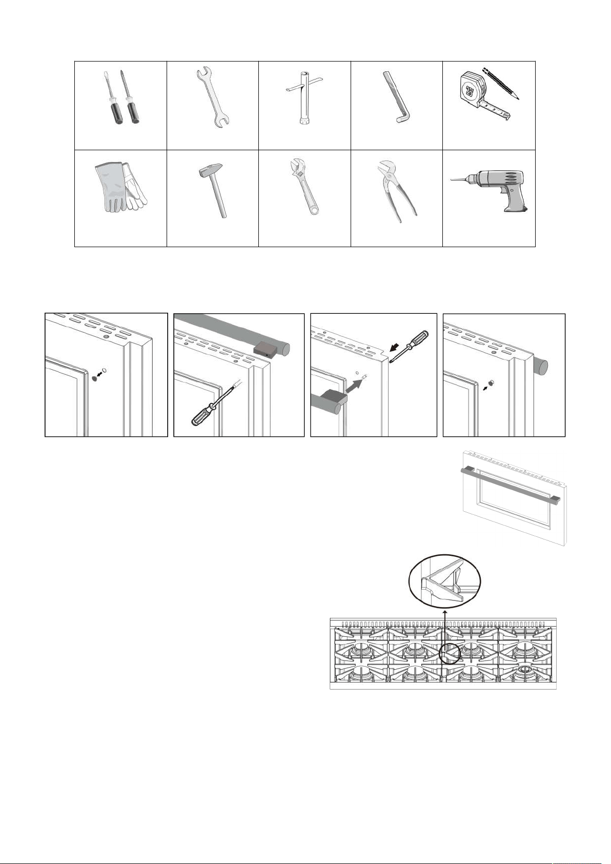
TOOLS NEEDED FOR INSTALLATION (not supplied with the range)
Screwdriver Wrench Socket wrench Allen key
Tape measure
&Pencil
Protective
gloves
Hammer
Adjustable
wrench
Adjustable pliers
Drill
Door Handle Installation
The door handle is not pre-installed. Follow the illustrations below to install the door handle quickly and easily.
Step 1. Remove the black rubber cap on the inside of oven door. (Do not throw it away).
Step 2. Insert the screwdriver to the hole to reach the embedded screw head.
Step 3. Position the handle holder correctly to accept the screw bolt on the outside of
oven door, screw the bolt half way into the handle holder.
Caution: Do not tighten the bolt to the handle holder before the handle holder of
the other end is positioned correctly.
Step 4. Repeat Step 1 to 3 for the other side. Tighten the bolt into the handle holder.
Tighten the bolt at the other side. Put the black rubber caps back to cover the holes on
the inside of oven door.
Surface Burner Grills Installation
Remove the packing materials from the surface burner
grills. Place the burner grills to the correct position.
Follow the illustration for proper direction when position
the middle grills on the cooktop for the 48” model.
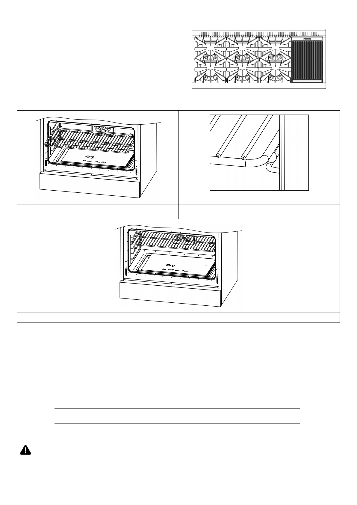
9
Put the griddle (for 48” model only) on any burner you
want to use.
Oven Rack Installation
Put the baking rack onto the side rail. Raise the backing rack a little bit so that the steel ball
underneath can cross the side rail.
Push the baking rack slowly all the way into the oven cavity.
Electrical
Your range must be electrically grounded in accordance with local codes or, in the absence of local codes, in
accordance with the National Electrical Code (ANSI/NFPA 70, latest edition). In Canada, electrical grounding must
be in accordance with the current CSA C22.1 Canadian Electrical Code Part 1 and/or local codes.
The power supply must be the correct polarity. Reverse polarity will result in continuous sparking of the electrodes,
even after flame ignition. If there is any doubt as to whether the power supply has the correct polarity or grounded,
have it checked by a qualified electrician.
ELECTRICAL REQUIREMENTS
Electrical Supply Grounded, 110/120 VAC, 60 Hz
Service 15 amp or 20 amp dedicated circuit
Receptacle 3-prong grounding-type
Power Cord 5.5' (1.4 m)
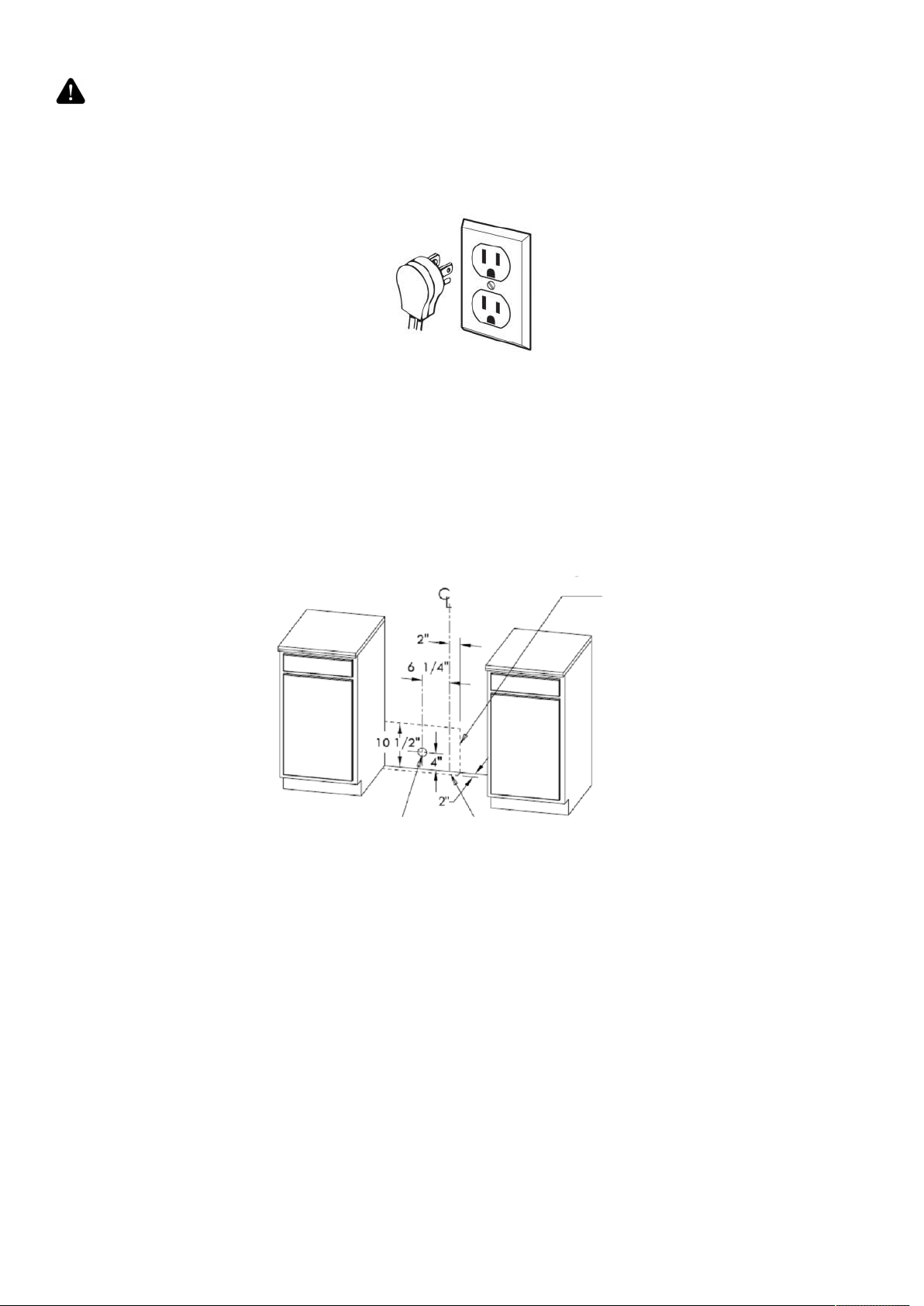
WARNING
Electrical grounding Instructions:
This range is equipped with a three-prong (grounding) plug for your protection
against shock hazard and should be plugged directly into a properly grounded
three-prong receptacle. DO NOT cut or remove the grounding pin from the plug
.
10
.
CAUTION
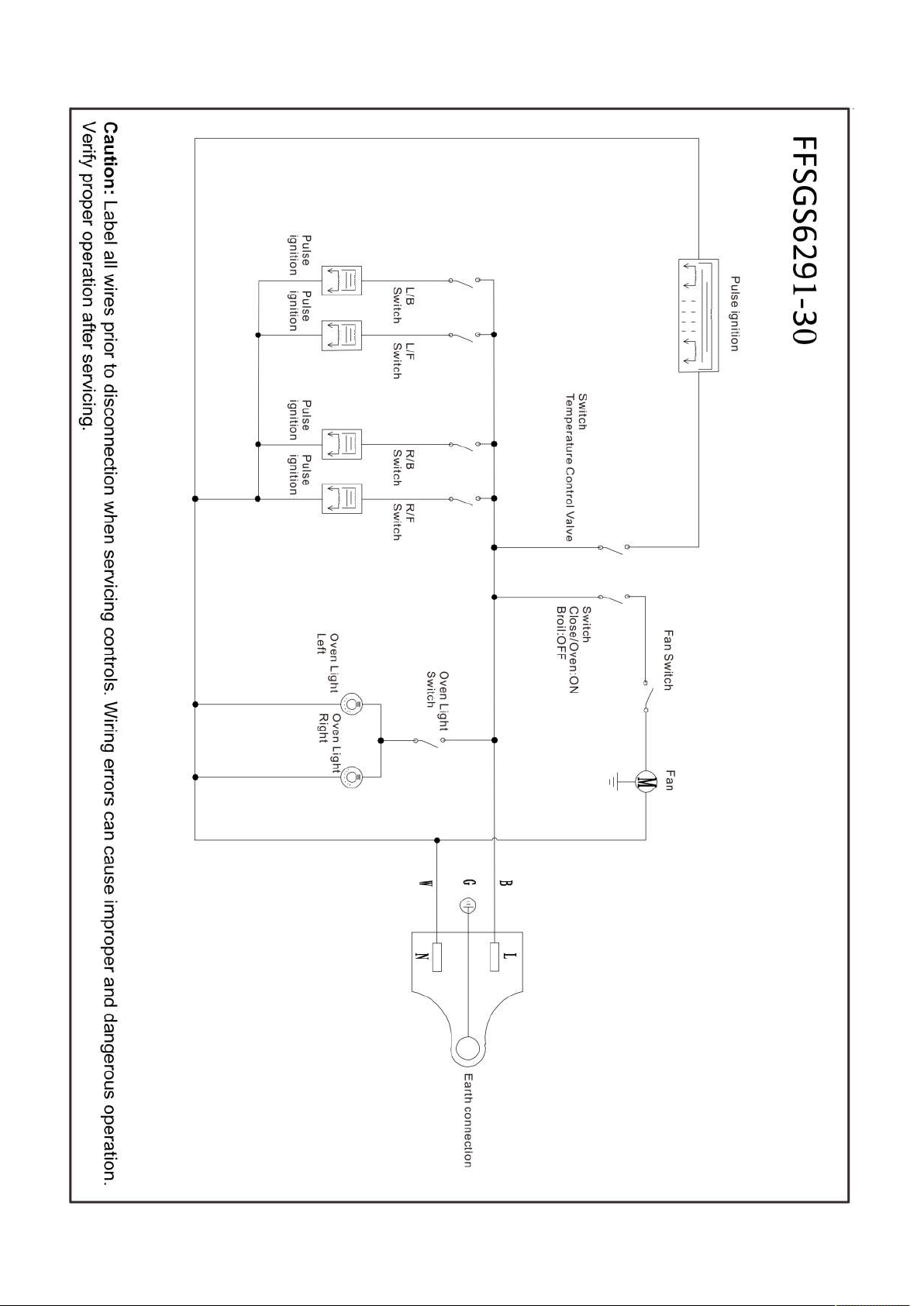
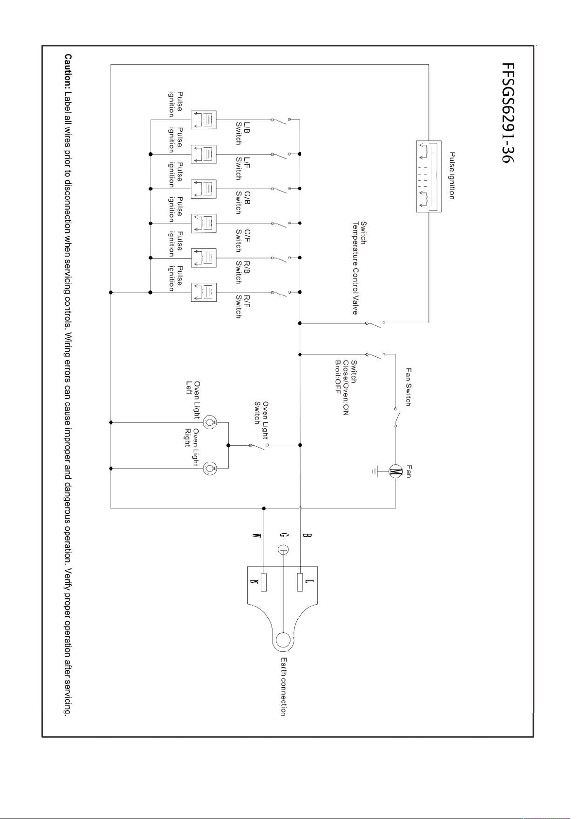
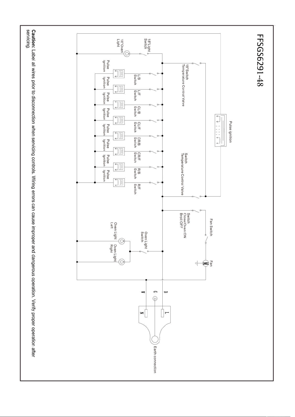
Label all wires prior to disconnection when servicing controls. Wiring errors can cause
improper and dangerous operation. Verify proper operation after servicing
ELECTRICAL SHOCK HAZARD
Disconnect electrical power at the circuit breaker box or fuse box
before installing the appliance. Provide appropriate ground for the appliance. Use copper conductors only. Failure
to follow these instructions could result in serious injury or death.
Grounding
The power cord is equipped with a three-prong(grounding) plug which mates with a standard three-prong
grounding wall receptacle to minimize the possibility of electrical shock hazard from the range.
All cord connected appliance shall include instructions relative to location of the wall receptacle and a warning to
the user to disconnect the electrical supply before serving the appliance.
Where a standard two-prong wall receptacle is encountered, it is the responsibility and obligation of the customer
to have it replaced with a properly grounded three-prong wall receptacle. Do not cut or remove the grounding
prong from the power cord.
Electric Power Supply Requirements
Gas Supply
Installation must comply with local codes or, in the absence of local codes, with the National Fuel Gas Code, ANSI
Z223.1 / NFPA 54. In Canada, installation must conform to the current natural Gas Installation /code, CAN
1-1.1-M81 and with local codes where applicable.
This range has been design-certified according to ANSI Z21.1b-2012 latest edition.
TYPE OF GAS:
NATURAL GAS WC
Supply Pressure 5" (12.5 mb)
Minimum Supply Pressure 6"
Max Regulator Pressure 14" (34.9 mb), 0.5 psi (3.5 kPa)
LP GAS WC
Supply Pressure 10" (25 mb)
Minimum Supply Pressure 11"
Max Regulator Pressure 14" (34.9 mb), 0.5 psi (3.5 kPa)
Area allows for flush installation with
through-the-wall connection of pipe
stub/shut-off valve and rear wall 120V
outlet.
Shortest connection from hard pipe stub location
to range hook-up.
Area allows for flush installation with through-the-floor
connection of pipe stub/shut-off valve
11
WARNING
Do not obstruct the flow of combustion air into the range and ventilation air away
from the range
Ventilation: it is recommended that the unit be operated with an oven head, vented exhaust hood of sufficient size
and capacity.
Pressure regulator
Since service pressure may fluctuate with local demand, every gas cooking range must be equipped with a
pressure regulator on the incoming service line for safe and efficient operation.
The pressure regulator shipped with the range has female threads 1/2”NPT for 30” & 36” range, or 3/4" NPT for 48”
range. The regulator shall be installed properly in order to be accessible when the appliance is installed in its final
position.
Pressure regulator can withstand a maximum input pressure of 0.5 psi (3.5 kPa), and is set at
5" wc out let pressure.
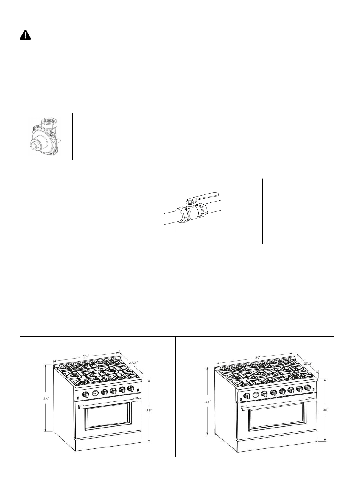
Gas Shut-off Valve (not included)
The supply line must be equipped with an approved external gas shut-off valve located near the range in an
accessible location. Do not block access to the shut-off valve. Refer to the illustration above.
A 3/4" (19) ID gas supply line must be provided to the range. If local codes permit, a certified, 3' (.9 m) long, 1/2"
(13) or 3/4" (19) ID flexible metal appliance connector is recommended to connect the unit’s 1/2" NPT or 3/4”NPT
female inlet to the gas supply line. Pipe joint compounds suitable for use with natural or LP gas should be used.
The appliance and its shut-off valve must be disconnected from the gas supply piping system during any pressure
testing of the system at test pressures in excess of 0.5 psi (3.5 kPa). The appliance must be isolated from the gas
supply piping system by closing its individual manual shutoff valve during any pressure testing of the system at test
pressures equal to or less than 0.5 psi (3.5 kPa).
Product Dimensions and Cabinets
Model#: FFSGS6291-30 Model#: FFSGS6291-36
shut-off valve at open position
Connect to
appliance
Gas supply
12
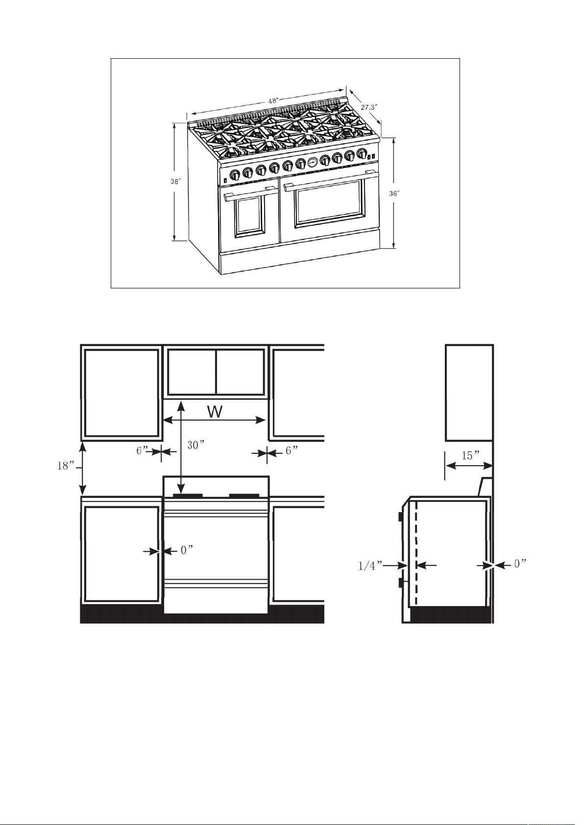
Model#: FFSGS6291-48
This range may be installed directly adjacent to existing countertop-height cabinets (36" or 91.5 cm from the floor).
To achieve the best look, the cooktop should be level with the cabinet countertop. This can be accomplished by
raising the unit using the adjustment spindles on the legs.
Opening width W
30" Model 30" (762mm)
36" Model 36" (914mm)
48" Model 48" (1219mm)
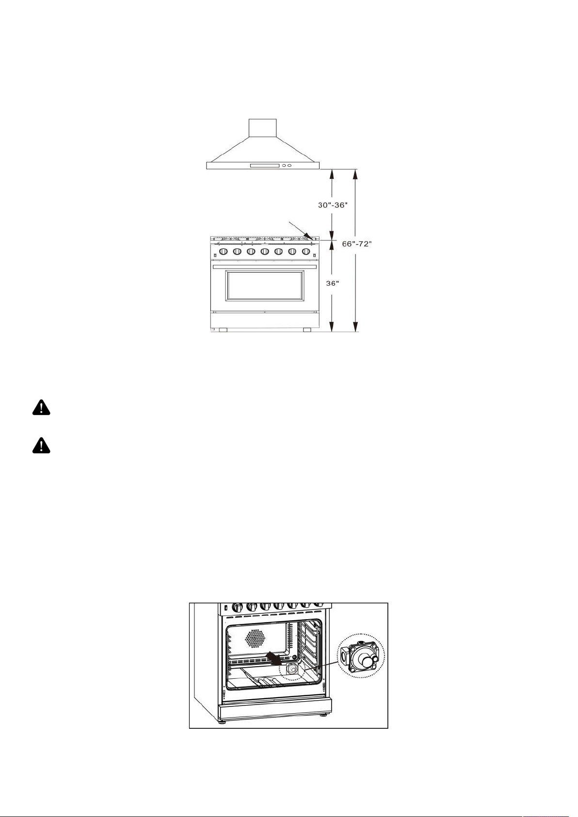
Exhaust Hood Installation
The bottom of the hood should be 30" min. to 36" above the countertop. This would typically result in the bottom of
the hood being 66" to 72" above the floor. These dimensions provide safe and efficient operation of the hood.
After Installation:
1. Check ignition of surface burners.
Minimum to
cabinets on either
sides of the range
Opening width
Min.
To wall either side
Maximum
depth for
cabinets above
countertop
Front edge of
the range
side panel
forward from
cabinet
To countertops
below cooktop
and at the
range back
13
2. Check the air shutter adjustment – sharp blue flame, with no yellow tipping or lifting flames.
3. Check ignition of oven burner.
4. Visually check tubular burner (oven burner) re-ignition to be sure both rows of burner ports are relighting each
time.
5. Check for gas leaks at all gas connections (using a gas detector, never a flame).
6. Check oven bake and convection bake function.
Gas Conversion Operation
This cooking range can be used with LP gas and NG gas. It is shipped from the factory adjusted for use with
NG(Nature Gas). Injector for LP gas are included. Follow the instruction shown below for gas conversion.
WARNING
Gas conversion shall be conducted by a factory- trained professional. Call the
customer service hotline to identify a factory-trained professional near your home.
WARNING
Before carrying out this operation, disconnect the range from gas and electricity.
Fail to do so, may result in fire, or electrical shock hazard can occur and result in
injury or death. Do not remove regulator or allow it to turn during servicing.
The gas conversion procedure for this range includes 8 steps:
1. Pressure regulator 5. Air shutter for oven burner (optional)
2. Surface burners 6. Gas valves
3. Oven burner 7. Reconnect Gas and Electrical Supply
4. Broil burner 8. Installation of new rating label
The conversion is not completed if all 8 steps have not been concluded properly.
Before performing the gas conversion, locate the package containing the replacement injectors shipped with every
range.
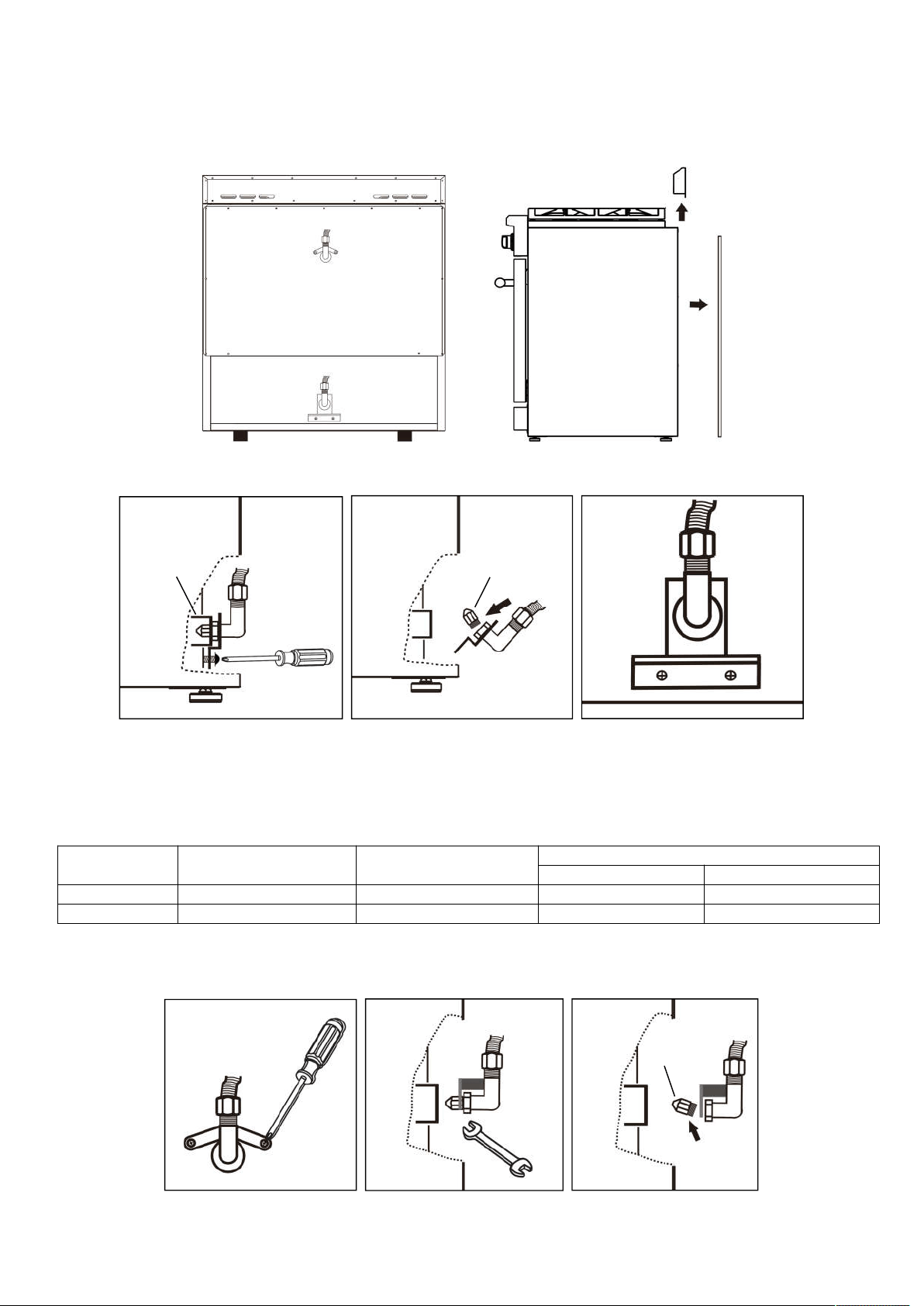
STEP 1: Pressure Regulator
The gas regulator is located at the bottom right corner inside the oven. Operate 3 steps to access the gas
regulator.
Counter top
14
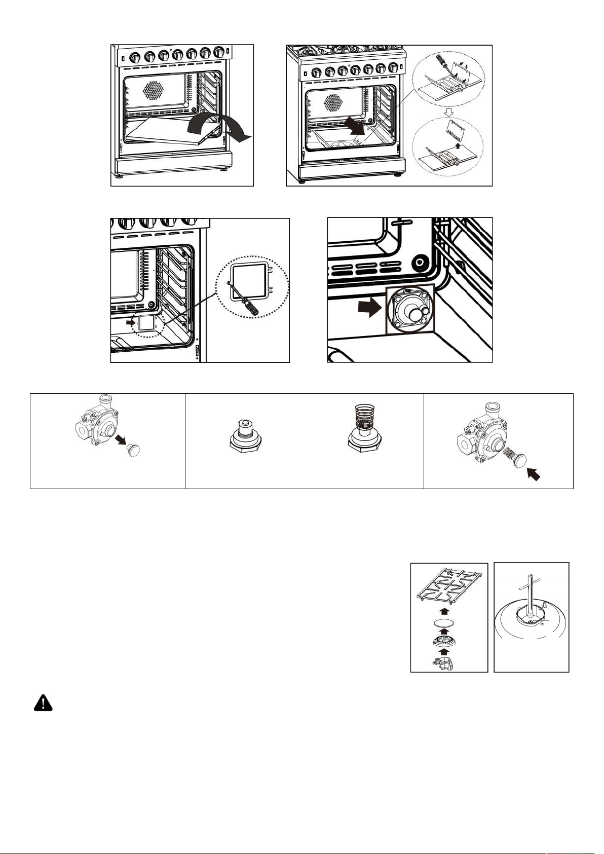
1.1) Take off the oven bottom cover plate.
1.2) Loosen 4 screws to take off the side guard plate on the right of the bottom burner.
1.3) Remove the small plate from the bottom right corner on the back wall, you will see the pressure regulator
through the hole.
Injector direction for NG Injector direction for LPG
1.4)Unscrew the cap with
injector from the regulator.
1.5)Unscrew the injector from the cap, do not
remove the spring from the injector. Reverse the
injector with spring and screw it back to the cap.
1.6)Screw the cap with
injector back to the regulator.
1.7)Assemble the small plate and burner side guard plate back to place, and put back the oven bottom cover.
STEP 2: Surface Burners
2.1)Remove cooking grates and burner caps.
2.2)Lift off burner spreader.
2.3)Remove the factory installed natural gas injector from the nozzle holders
by using a 7mm socket wrench.
2.4)Replace the LP injector in each nozzle holder. Tighten each injector
properly. Do not to over tighten the injector.
2.5)Place the burner spreader and caps back to correct position. Put back
the cooking grates.
CAUTION
Handle carefully when removing and replacing gas components. Use proper
support to prevent damage to components.
IMPORTANT: Each injector has a number indicating its flow diameter, the number is printed on the body. Consult
the table below for matching nozzles with surface burners.
Socket
15
Model#: FFSGS6291-30
Model#: FFSGS6291-36
Model#: FFSGS6291-48
9000BTU
NG: 1.33
LPG: 0.93
9000BTU
NG: 1.33
LPG: 0.93
15000BTU
NG: 1.75
LPG: 1.18
15000BTU
NG: 1.75
LPG: 1.18
20000BTU
NG: 1.38×2(outer)
0.75×1(center)
LPG: 0.9×2(outer)
0.46×1(center)
9000BTU
NG: 1.33
LPG: 0.93
15000BTU
NG: 1.75
LPG: 1.18
9000BTU
NG: 1.33
LPG: 0.93
9000BTU
NG: 1.33
LPG: 0.93
15000BTU
NG: 1.75
LPG: 1.18
15000BTU
NG: 1.75
LPG: 1.18
15000BTU
NG: 1.75
LPG: 1.18
9000BTU
NG: 1.33
LPG: 0.93
15000BTU
NG: 1.75
LPG: 1.18
9000BTU
NG: 1.33
LPG: 0.93
15000BTU
NG: 1.75
LPG: 1.18
15000BTU
NG: 1.75
LPG: 1.18
20000BTU
NG: 1.38
×
2(outer)
0.75×1(center)
LPG: 0.9
×
2(outer)
0.46×1(center)
16
IMPORTANT: SAVE THE NOZZLES REMOVED FROM THE RANGE FOR FUTURE USE.
STEP 3: Oven Burner
The nozzle of the oven burner locates in the bottom rear of the cooking range.
3.1)Pull the unit out of its place.
3.2)Disassemble the oven vent and back plate.
3.3) Remove 2 screws, loosen the bracket to access the injector. Replace the injector and tighten. Aligning the new
injector with the air shutter.
3.4) Assemble the bracket back to place.
Repeat above steps for 18”oven (for 48" ranges only).
Injector diameter for oven bottom burners:
Model# FFSGS6291-30 FFSGS6291-36
FFSGS6291-48
30” oven 18” oven
NG 2.26 2.26 2.26 1.71
LPG 1.39 1.39 1.39 1.12
STEP 4: Broil Burner (oven top burner)
Broil burner nozzle locates in the middle top of cooking range back. Pull the unit out of its place. Take out the oven
vent and back plate.
4.1)Remove 2 screws to loosen injector bracket.
Broil burner nozzle
Oven burner nozzle
Air shutter
injector
injector
17
4.2)Use open wrench to remove the gas line from the injector holder. Replace the broil burner injector from the
orifice holder.
4.3)Assemble the bracket back to place.
Injector diameter for oven broil burners:
Model# FFSGS6291-30 FFSGS6291-36 FFSGS6291-48
NG 1.38 1.38 1.38
LPG 0.94 0.94 0.94
IMPORTANT: Keep the injectors removed from the range for future use.
STEP 5: Air Shutter for Oven Bottom & Top Burner (Optional)
The air shutter for the oven burner may need adjustment, especially if the unit has been converted for use with LP
from NG. The approximate height of the flame at the oven burner is one inch (distinctive inner blue flame).
To determine if the air shutter of oven burners need to be adjusted:
Set the oven knob to 350°F position or broil and observe the flame color. If yellow flame can be seen, need to
increase the air shutter opening. If the flame is blue and lifting away from the burner, need to reduce the air shutter
opening.
5.1)Turn off the oven and allow it to cool before adjusting the air shutter.
5.2)Disassemble the burners to access the air shutter.
5.3)To adjust the air shutter, loosen the lock screw, re-position the air shutter and tighten the lock screw.
5.4)Assemble the burners back to place.
5.5)Retest the burner. When the flame is a distinct blue color and burning steadily, the air shutter is adjusted
correctly.
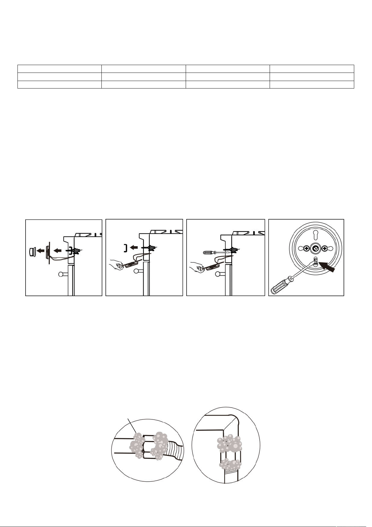
STEP 6: Gas valve (adjusting gas inlet orifice for surface burner)
After converting nozzle for different gas type, the gas inlet hole of surface burner needs to be adjusted.
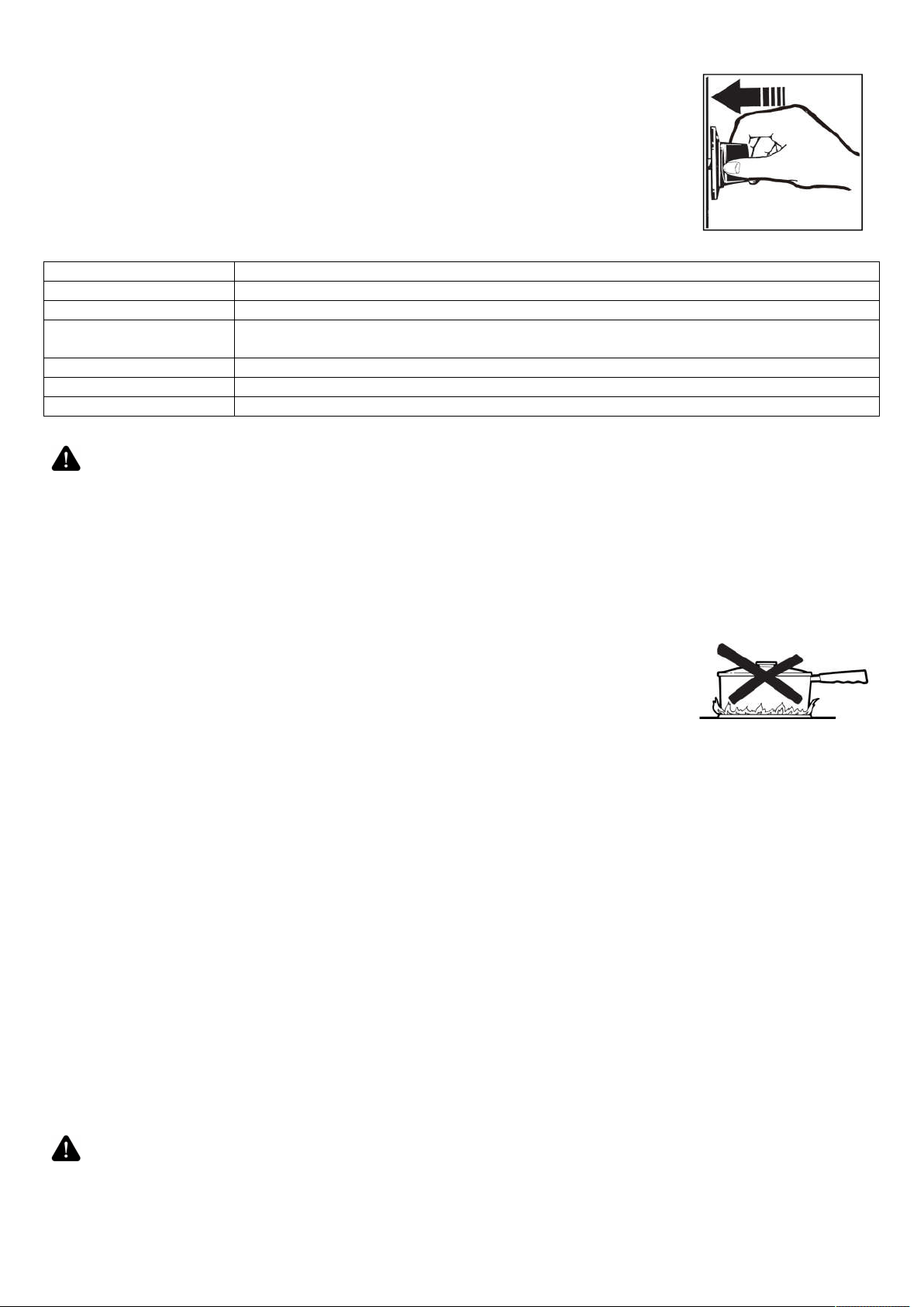
6.1)Remove control knobs.
6.2)Disassemble the control panel and hold it. Be careful not to damage the wiring connected to the temperature
gauge.
6.3)Take out the heat-isolating gasket (black silicon gasket).
6.4)Use screwdriver to adjust main burner bypass screw clockwise or anticlockwise until the flame is normal.
6.5)Place the silicon gasket and control panel back to place, tighten properly.
6.5)Put back knobs to the correct position.
STEP 7: Reconnect Gas and Electrical Supply
Leakage testing of the range shall be conducted according to the installation instructions provided with the range.
Before operating the range after the gas conversion, always check for leaks with a soapy water solution or other
acceptable method at gas connections installed between the gas inlet pipe of the range, gas regulator, and the
manual shut-off valve.
Use soapy solutions to check for leakage on all joints.

18
WARNING
DO NOT use a flame to check for gas leakage.
STEP 8: Installation of LPG Conversion Label
Record the model and serial number on the LP / Propane Conversion Label provided in this kit.
The information can be obtained from the existing Rating / Serial label. Place the LPG conversion label as close as
possible to the existing Rating / Serial label on the range.
Preparation
Before moving the range, protect any finished flooring and secure oven door(s) closed to prevent damage.
The oven door(s) can be removed to lighten the load or to fit the unit through a doorway. Only remove if necessary.
Do not remove the griddle or any other component. Door removal should only be done by a certified installer or
service technician.
Placement
Do not lift or carry the oven door by the door handle. Use an appliance dolly to move the range near the opening.
Remove and recycle packing materials. Do not discard the anti-tip bracket supplied with the range.
Leveling
Raise the range to the desired height by adjusting the legs. The legs can be adjusted by rotating clockwise to raise
or counter clockwise to lower the range.
Anti-Tip Bracket
To prevent the range from tipping forward, the anti-tip bracket must be installed. Refer to the section of ANTI-TIP
DEVICE.
Gas Supply Connection
All connections to the gas piping must be wrench-tightened. Do not over-tighten or allow pipes to turn when
tightening.
When all connections have been made, check that all range controls are in the “OFF” position and turn on the main
gas supply valve.
If a flexible metal connector is being used, verify it is not kinked, then attach the gas supply line to the regulator on
the range. Open the valve and check for leakage by placing a liquid detergent solution onto all gas connections.
Bubbles around connections indicate a gas leak. If a leakage is determined, close the shut-off valve and fix the
connections.
Leakage testing of the appliance shall be conducted according to the manufacture’s instructions . Use some soap
water (50% water and 50% soap) or a leakage detector at all joints and connections to check for leaks in the
system. Do not use a flame to check for gas leaks.
The appliance must be isolated from the building’s gas supply piping system by closing its individual manual
shut-off valve during any pressure testing of the gas supply piping system at test pressure equal to or less than 0.5
psi (3.5kPa).
Getting Started
Before you start cooking, please take the following steps.
• Remove all the exterior and interior packing.
• Remove the protective film on steel and aluminum parts.
• Clean the range thoroughly with hot water and a mild detergent. Rinse and dry with a soft cloth to remove any
residual oil and grease left over from the manufacturing process.
• Check that surface burner components are assembled correctly.
• Furnish the interior of the oven by inserting the shelves and tray.
Surface Burner Operation
The burner assembly contains all accessories in one set. The burner cap must
be seated on the burner horizontally. Refer to the illustration.
Burner cap
Burner
igniter
19
Ignition
To light up the cooktop burners, push and turn the appropriate control knob counter
clockwise to “Hi” position. You will hear a clicking noise – the sound of ignition pin
sparking.
Once burner ignition has been achieved, turn the burner control knob to adjust desired
flame size. If the knob stays at “Hi”, it will continue clicking.
Heat Settings:
Hi Ignites the burners.
Simmer Melting small quantities, steaming rice, warming food, melting chocolate or butter.
Low Melting large quantities.
Low-Medium Low-temperature frying, simmering large quantities, heating milk, cream sauces,
gravies.
Medium Sauteing and browning, braising, pan-frying, maintaining slow boil on large quantities.
Medium-Hi High-temperature frying, pan boiling, maintaining slow boil on large quantities.
Hi Boiling liquid quickly, deep frying.
CAUTION
Never leave pans on a high setting unattended. Be careful when cooking food in
fat or grease; it can become hot enough to ignite. Burner flames not covered by
cookware present a risk of fire or clothing ignition. Never let flames extend beyond
the sides of the cookware. Failure to comply may result in serious injury.
Simmer and Boil
A smaller flame will give the best results when simmering. Small flames offer precise cooking performance for
delicate foods, keeping food warm, melting chocolate or butter, and for cooking over low heat for long period of
time.
The highest (larger) flame settings provide the maximum heat that is available on your range. This setting should
be used for heavy cooking jobs such as boiling water and cooking pasts.
Flame Size
• When you adjust the flame size, watch the flame when you turn the knob.
• Any flame exceeding the bottom of the cookware will not heat faster and may be
hazardous .
• The flame should be steady and blue in color. Impurity in the gas supply may cause
an orange flame during initial operation.
Power Failure
• If the gas does not ignite within 4 seconds, turn off the valve and allow at least five minutes for any gas to
dissipate. Repeat the lighting procedure.
• In the event of a power failure, the surface burners can be lighted manually. Hold a lighted match near a burner
and turn the knob counter-clockwise to “HI”. After burner lights, turn knob to the desired setting.
Burner Grills
1. The grills must be properly positioned before cooking. Improper installation of the grills may result in scratching
of the cooktop and / or poor combustion.
2. Do not operate the burners without a pan or utensil on the grills.
Griddle Operation (Only available on the 48”models)
Before Using the Griddle
1. Clean the griddle thoroughly with warm, soapy water to remove dust or any protective coating.
2. Rinse with clean water and wipe off to dry with soft, clean, lint-free towel/cloth.
Use of Griddle
1.Place the griddle to the position you need to cook.
2. Preheat the griddle for 10-12 minutes.
3. Butter or cooking oil can be added for more flavor, then place the food to cook.
CAUTION
The surface of the grill is hot after use. Please allow sufficient time for the grill to
cool before cleaning.
Cooptop cleaning tips
20
• To prevent the cooktop from discoloring or staining, clean cooktop after each use, and wipe up acidic or sugary
spills as soon as the cooktop is cooled.
• The sealed burners of your range are not secured to the cooktop and are designed to be removed easily. Boil
overs or spills will not seep underneath the cooktop. The burners should be cleaned after each use.
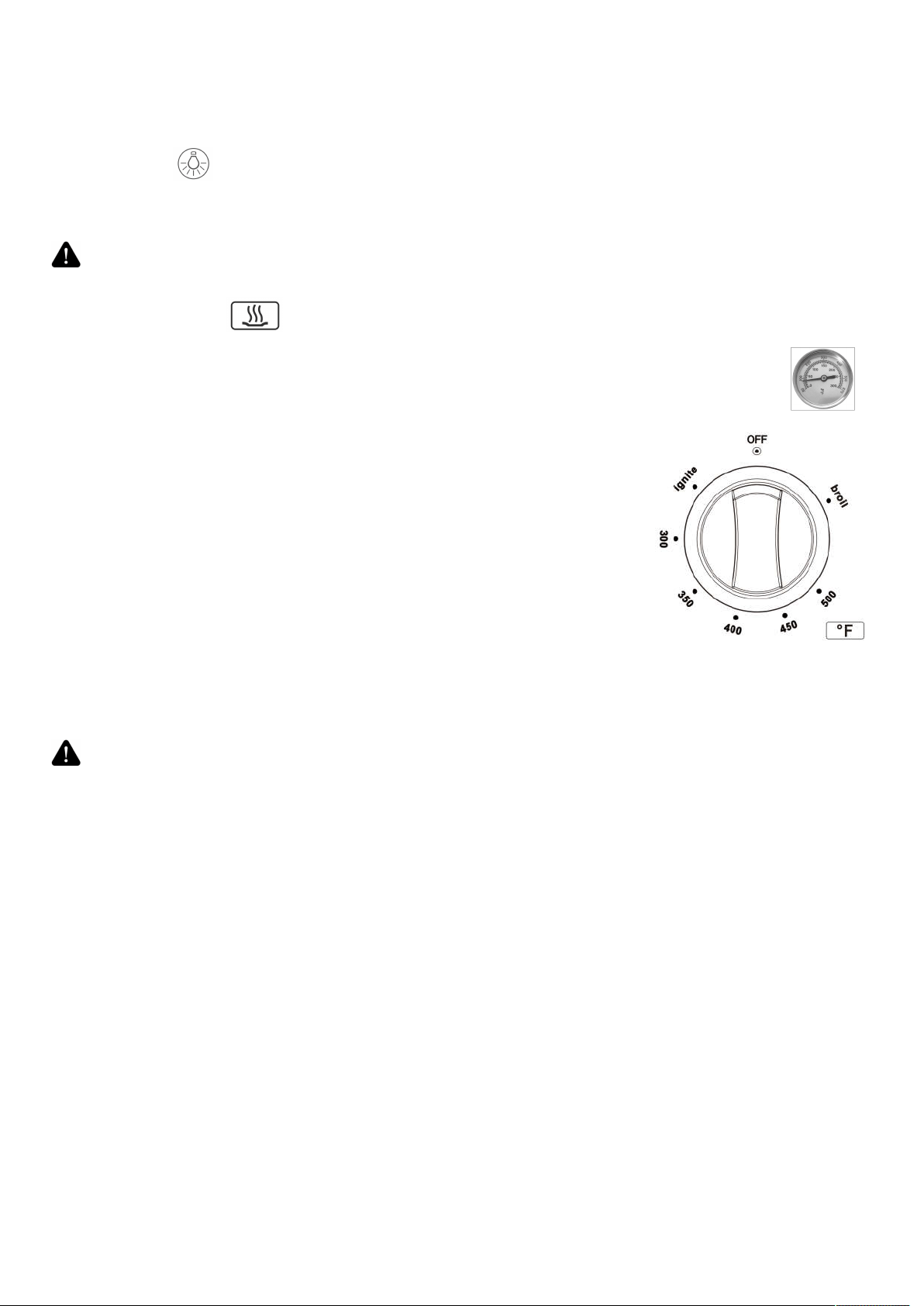
Oven Light
The oven light is controlled by a push switch on the control panel.
The light can be used while cooking or cleaning the oven.
WARNING
Before replacing the oven light, make sure power is disconnected from the
electrical box and the oven is cooled completely. Disassemble the light cover and
replace the light bulb with a 40-watt halogen bulb. Install the light cover properly.
Oven Operation
Temperature gauge
1. The gauge shows the oven temperature in both CELSIUS degree and FAHRENHEIT degree.
2. Correct reading can be obtained when the temperature inside the oven is steady.
3. For model FFSGS6291-48, the gauge is available for the big oven(30” oven) only.
Oven Ignition
The oven is equipped with an ignition system which contains pilot flame function
and safety device. To light up the oven burner, push and turn the oven control
knob anti-clockwise to reach IGNITE position and hold it. You will hear a clicking
noise - the sound of ignition pin sparking. Hold the knob until you can see the
pilot flame on.
To light up the broil burner, push and turn the oven control knob clockwise to
“Broil” position and hold it. You will hear a clicking noise - the sound of ignition pin
sparking. Hold the knob until you can see the burner is lighted up.
DO NOT RELEASE the knob before you can see the flame comes up. If fail to
light up the oven burner within 10 seconds, reset the oven control knob to the
“OFF” position, repeat above operations until the oven burner is properly ignited.
IMPORTANT
Safety device is equipped with the oven burner. When the flame goes out by accident, the gas
supply will be shut off automatically. You need to turn the control knob back to the “OFF”
position and ignite again.
WARNING
If fail to light up the oven burner 3 times continuously, the oven might full of the gas, then
open the oven door to allow gas dissipating before operating ignition again. Otherwise,
the oven may explode and the user will get hurt.
Oven Baking Tips
For fast exhausting the smell of "burning" or "oily" odor emitting from a new oven, turn the oven knob to "Broil" and
run for 30 minutes before initial use.
1. Never cover any slots, holes or passages in the oven bottom or cover an entire rack with materials such as
aluminum foil. Doing so blocks air flow through the oven and may cause carbon monoxide poisoning. The
aluminum foil lining may also trap heat, causing a fire hazard.
Do not use aluminum foil on any porcelain surface. Doing so will damage the porcelain and affect its durability.
2. Position the racks before preheating the oven.
Preheating
Allow the oven to preheat before placing food in the oven. Preheating is necessary for good results when baking
cakes, cookies, pastry and breads.
Remove the broiler pan before preheating with the infrared broiler. Foods will stick on hot metal.
To preheat, turn the “Oven” control knob to the “Broil” position. Wait for the burner to become hot, approximately in
2 minutes.
Note: Condensation or fogging on the inside of the oven door glass is normal while preheating and it will usually
evaporate by the end of the preheating cycle
Oven Function
Natural Airflow Bake occurs when heat is transferred into the oven from the bake burners in the bottom of the oven
cavity. Heat is then circulated by natural airflow.This is a traditional bake setting.

21
Convection Bake
Heat is transferred from the bake burners in the bottom of the oven cavity to the oven cavity itself.
The convection fan at the rear of the oven then circulates it. This convection process provides a more even heat
distribution throughout the oven cavity.
Using multiple racks is possible for large-batch baking. Convection cooking is faster, can be done at lower
temperatures and provides more even temperatures than regular cooking.
Convection Roast
The convection fan circulates the heated air evenly over and around the food. Using the cover and broiler pan (not
provided), heated air will be circulated over the around the food being roasted. The heated air seals in juices
quickly for a moist and tender product, while at the same time creating a rich golden brown exterior. When
convection roasting, it is important that you use the broiler pan for best convection roasting results. The pan is
used to catch grease spills and has a cover to prevent grease splatters.
Convection Defrost
With temperature control off, the motorized fan in the rear of the oven circulates air. The fan accelerates natural
defrosting of the food without heat. To avoid illness and food waste, do not allow defrost food to remain in the oven
for more than two hours without being cooked.
Broiler Operation
Note: Door must be closed during broiling operation.
The broil burner is located at the top of the oven. This burner heats the metal screen until it glows. The glowing
screen produces heat, searing the outside of broiled foods and sealing in juices. Broiling is a method of cooking
tender cuts of meat directly under the broiler in the oven.
Oven broiling is done with the oven door closed. It is normal and even necessary to have some smoke to give the
food a broiled flavor
Setting Broil
Turn the oven control knob clockwise to select the Broil function. When broiling, heat radiates downward from the
oven broiler. The temperature of Broil feature is 500˚F (260˚C).
Used together, the broil pan and insert(not included) allow dripping grease to drain and be kept away from the high
heat of the oven broiler. DO NOT use the broil pan without the insert. DO NOT cover the broil pan insert with foil.
The exposed grease could catch fire. To set the oven to Broil:
1. Place the insert on the broiler pan. Then place the food on the pan insert.
2. Adjust the interior oven rack to the desired position and place the broiler pan on the rack. Be sure to center the
pan and position it directly under the broil burner. (If preheating is needed, put in the pan after the broil burner
reaches the temperature.)
3. Turn the control knob to Broil setting position.
The oven indicator will remain on until the control knob is turned to the OFF position or the temperature control
cycles off.
Position the rack at the correct level. The farther away the food is from the broiler, the more well done it will be
inside. Preheating the oven is not necessary. Push in and turn the knob to BROIL. Turn the food over at the
halfway point. Always pull the rack out to the “stop” position before turning or removing food.
Oven Cleaning Tips
1. After each use, and once the oven is cooled, clean splatters and spills immediately.
2. Do not allow foods with a high sugar or acid content to remain on the oven cavity surface.
3. Use an oven cleaner to clean the oven cavity.
Oven Thermostat & Cooking time
The numbers printed on the control panel indicate the oven temperature setting
value (°F). To set the temperature, adjust the control knob indicator to line up with
the desired number on the control panel.
Note: The BROIL function is only for turning on the broil burner.
Cooking times can vary according to the type of food, its density and its size. It is
advisable to watch when cooking for the first time and to check results since similar
results are obtained when preparing the same dishes under the same conditions.
Use the thermostat to control the temperatures, and control the time according to
the cooking guides.
Thermostat is equipped in the oven, when the oven temperature reaches the setting, the oven temperature will
stay relatively stable. Actual oven temperature can be read from the gauge on the control panel.
22
Care and Maintenance Recommendations
Stainless steel Use non-abrasive stainless steel cleaner, apply small amount to a soft cloth, slightly wipe the
stainless steel surface, then towel dry. When wiping on the stainless steel surface, always
follow the grain of the metal.
Burner grills
Oven rack
guides
Clean with hot water and mild detergent or mixture of baking soda and water. Do not immerse
in water. Towel dry.
Burner pan Remove surface debris before cleaning to help speed up the process and decrease the chance
of scratching the surface during cleaning. Using mild abrasive cleaners or spray degreasers,
clean and rinse the surface and dry immediately. To clean hard water stains, use white vinegar
and water. Rinse and dry immediately.
Cooktop burners After cool down, use mild detergent or spray degreaser to clean. Rinse with water and towel
dry.
Control knobs Using a damp cloth, wipe with a mild detergent or spray degreaser; rinse and dry. Do not place
in dishwasher.
Oven interior Use mild abrasive cleaners, spray degreasers. Use a razor blade to gently remove baked on
foods from oven cavity and window. For stubborn stains, spray with a mild abrasive cleaner or
spray degreaser. Clean the entire oven cavity with soap and water.
Broiler pan To clean the upper rack, use mild detergent and a scouring pad. Rinse and dry. To clean the
bottom pan, discard grease and wash with hot water and mild detergent. Rinse and dry.
Troubleshooting Tips
Before you call for service
Range does not operate Check that power is on.
Check that electrical power to range and home circuit breaker is on.
Burners Do Not Light Or
Spark Randomly
Electrical plug is not connected properly with a live power outlet.
Gas supply not turned on.
Burner parts not replaced correctly.
Holes in the simmer rings or slits in the burner rings are clogged.
Clogged nozzles, or wet burners or electrodes.
A fuse in your home may be blown or circuit breaker tripped.
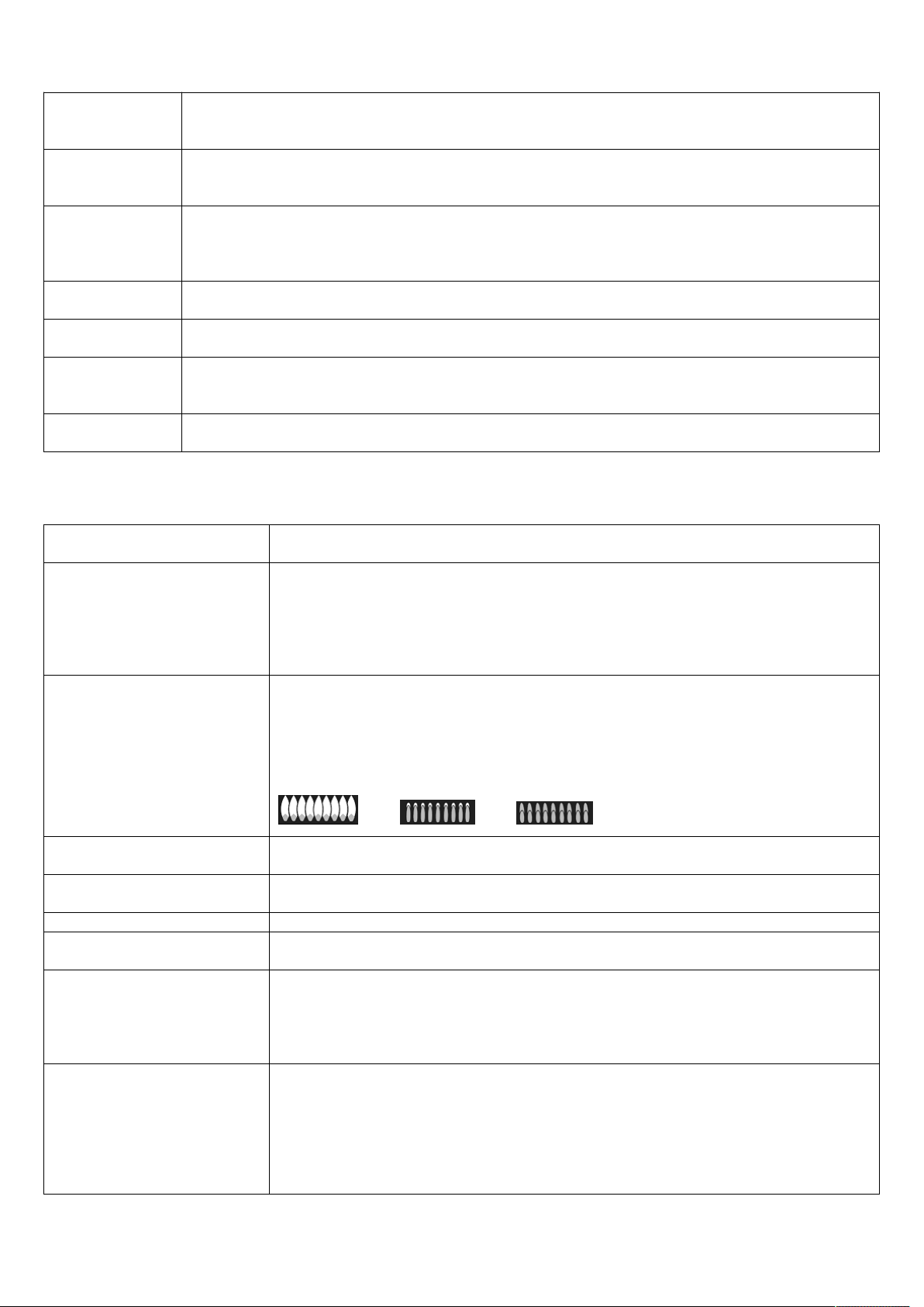
Burners Have Yellow Or
Yellow-Tipped Flames
Burner parts not replaced correctly.
A. Yellow flames: Call for service.
B. Yellow tips on outer cones: Normal for propane (LP) gas.
C. Soft blue flames: Normal for natural gas.
If burner flames look like (A), call for service.
Normal burner flames should look like (B) or (C), depending on the type of gas.
(A), (B), (C)
Burner Flames Very Large
Or Yellow
The range may be connected to the wrong fuel type. Contact the person who
installed your range or made the conversion.
Burner Flames Contain
Orange Flickers
Airborne dust; cool-mist humidifier; debris on or inside burner.
Oven Lights Do Not Work The light bulb is defective. Replace the bulb.
Oven Racks Are Hard To
Slide
Do not use a cooking spray or other lubricant sprays to make it smooth.
Refer to oven racks cleaning in the Care and Maintenance section.
Food Does Not Bake Or
Roast Properly
The oven controls are improperly set. See the Baking or Roasting section.
Oven not preheated for enough time.
Incorrect cookware or cookware of improper size being used.
Racks in the wrong position. See the Baking or Roasting section.
Use a foil tent to slow down browning during roasting.
Food Does Not Broil
Properly
This model is designed for closed door broiling only. Always broil with the door
closed.
The oven controls are not set at BROIL. See the Broiling section.
Improper rack position.
Cookware is not suited for broiling.
Aluminum foil used on the broiling pan and rack has not been fitted properly and
slit as recommended.

23
Steam From The Vent When using the convection mode, it is normal to see steam coming out of the oven
vent. As the number of racks or amount of food being cooked increases, the
amount of visible steam will increase.
Burning Or Oily Odor
Emitting From The Vent
This is normal in a new oven and will disappear in some time.
Strong Odor This is temporary. An odour caused by the insulation around the inside of the oven
is normal for the first few times the oven is used.
Condensation Or Fogging
On The Glass of inside of
Oven Door.
Condensation or fogging on the glass of inside of oven door is normal during the
preheating of the oven and will evaporate usually by the end of the preheating
cycle.
Cracking Or Popping Sound
During Cleaning
This is normal. This is the sound of the metal heating and cooling during both the
cooking and cleaning functions.
Excessive Smoking Occurs
During Cleaning
The oven is heavily soiled. Turn the oven control knob to OFF. Open the windows
to exhaust. Wait until the oven is completely cooled. Wipe up excess soil and do
the cleaning again.
24
WIRE DIAGRAM
25
26