PACKAGED TERMINAL
AIR CONDITIONER/HEAT PUMP
INSTALLATION/OWNER’S MANUAL

Thank you for choosing an
You can feel confident in your selection because the same pride in craftsmanship
and engineering knowledge that goes into millions of other Gree installed
products worldwide has gone into your unit.
Please read this owner’s manual carefully before operation and retain it for
future reference.
ETAC II Packaged Terminal
Air Conditioner & Heating Unit!
Table of Contents
Safety Considerations . . . . . . . . . . . . . . . . . . . . . . . . . . . . . . . . . . . . 2
Nomenclature . . . . . . . . . . . . . . . . . . . . . . . . . . . . . . . . . . . . . . . . . . 3
Unit Features . . . . . . . . . . . . . . . . . . . . . . . . . . . . . . . . . . . . . . . . 4-6
Electrical Data . . . . . . . . . . . . . . . . . . . . . . . . . . . . . . . . . . . . . . . . 7-8
Installation . . . . . . . . . . . . . . . . . . . . . . . . . . . . . . . . . . . . . . . . . 9-13
System Configuration . . . . . . . . . . . . . . . . . . . . . . . . . . . . . . . . 14-20
Operation . . . . . . . . . . . . . . . . . . . . . . . . . . . . . . . . . . . . . . . . . . . . 21
Care and Cleaning . . . . . . . . . . . . . . . . . . . . . . . . . . . . . . . . . . 22-23
Troubleshooting . . . . . . . . . . . . . . . . . . . . . . . . . . . . . . . . . . . . 24-25
Warranty . . . . . . . . . . . . . . . . . . . . . . . . . . . . . . . . . . . . . . . . . . . Back
Model:
Serial:

SAFETY CONSIDERATIONS
PERSONAL INJURY AND/OR PROPERTY DAMAGE HAZARD
Failure to follow this warning could result in personal injury, death and/or property damage.
For your safety, the information in this manual must be followed to minimize the risk of fire
or explosion, electric shock, or to prevent property damage, personal injury, or loss of life.
• This unit must be properly installed in accordance with the Installation Instructions
before it is used.
• Immediately repair or replace all electric service cords that have become frayed or
otherwise damaged with original equipment manufacturer's (OEM) power cord.
• Unplug the unit and/or disconnect, lockout and tag electrical power at the fusebox or
circuit breaker before making any repairs.
N
O
T
E
:
W
e
s
t
r
o
n
g
l
y
r
e
c
o
m
m
e
n
d
t
h
a
t
a
n
y
s
e
r
v
i
c
i
n
g
b
e
p
e
r
f
o
r
m
e
d
b
y
a
q
u
a
l
i
f
i
e
d
i
n
d
i
v
i
d
u
a
l
.
2
Please read the following before installation or use.
Recognize safety information. This is the safety-alert symbol. When you see this
symbol on the unit and in the instructions or manuals, be alert to the potential for
personal injury. Understand these signal words: DANGER, WARNING, and CAUTION.
These words are used with the safety-alert symbol.
DANGER – identifies the most serious hazards which will result in severe personal
injury or death.
WARNING – signifies hazards which could result in personal injury or death.
CAUTION – is used to identify unsafe practices which may result in minor personal
injury or product and property damage.
NOTE – is used to highlight suggestions which will result in enhanced installation,
reliability, or operation.
WARNING
CA U TION
WARNING
WARNING
CAUTION
WARNING
WARNING

GENERAL
Gree packaged terminal air conditioners and heat pumps provide a high standard of quality
in performance, workmanship, durability and appearance as they heat and cool the occupied
air space year round. This manual provides information for ease of installation, operation and
maintenance. All models are designed for through-the-wall installation. Separate installation
instructions are included with all accessory components.
BEFORE YOU BEGIN: Read these instructions completely and carefully.
IMPORTANT: Save these instructions for local inspector’s use.
IMPORTANT: Observe all governing codes and ordinances.
NOTE TO INSTALLER: Be sure to leave these instructions with the owner.
NOTE TO OWNER: Keep these instructions for future reference. Be sure to write down the
model and serial number of unit on the space provided on the front page. The model and serial
number can be located on the serial number plate attached to unit.
UNIT INFORMATION
NOMENCLATURE
noitcetorPlatnemnorivnE
noitangiseDseireS
noitcetorPdradnatS-A
PTAC
ETAC
ETAC2
CP - Sea Coast Protection
Revision Level
Cooling Capacity
07 - 7,000 BTUH
HUTB000,9-90
HUTB000,21-21
HUTB000,51-51
gnitaRlacirtcelEepyTledoM
HP1zH06V032/802-V032pmuPtaeH-PH
HP1zH06V562-V562looC/taeH-CH
ETAC2
12 HP 230V -AA
Example: ETAC2-12HP230VA-A
Fig. 1 – Unit Name Plate & Nomenclature Chart
32
The unit nameplate is located beneath the front panel on the front lip of the base pan.
The nameplate contains the model and serial numbers of the unit. It also contains important
electrical and operational specifications. See Fig. 1.
ETAC2-12HP230VA-A
13516GAOO123
UNIT FEATURES
This ETAC II has many exciting features which are different than those found on standard PTAC
models. The owner must be familiar with these features in order to fully understand the operation
and capability of the unit.
• Intelligence
– Your ETAC II unit has an on board computer that utilizes real time diagnostics
to prolong the life of your unit. There is an LED indicator on the control board, behind the front
panel, that will flash an error code if the unit has detected some type of fault condition. In
many cases, the unit will automatically clear the fault condition and continue operating with
no interruption. In some cases, the condition cannot be cleared and the unit will require service.
In those cases, an “Fx” failure mode will be displayed on the digital display. For a detailed list
of all error codes and “Fx” conditions, see Intelligent Self Checking and Control section on page
20 for further details.
• Memory
– Your ETAC II unit also has memory. If power is lost, all of the control settings (set-
point, mode, fan speed, on/off and configuration) are remembered. So when power is restored,
the unit will start back up in the mode (and configuration) it was in, when power was lost.
•
Premium Sound
– Your Premium ETAC II is also the quietest Gree PTAC. Not only does it have
2 fan motors and a tangential blower wheel for optimum sound, the indoor fan will always run
a minimum of 10 seconds before the compressor, to help reduce any compressor starting noise.
• Random Compressor Restart
– To help prevent power surges after a power outage (from
many of your ETAC IIs starting at the same time), the compressor is equipped with a 165 to
195 second random restart delay feature. Whenever the unit is plugged in, or power has been
restarted, a random compressor restart will occur.
• Dry Mode
– will help to manage and reduce the humidity in the room, making it more
comfortable. In DRY mode, the unit will modulate cooling mode at low fan speed until the
room temperature is 4 deg. F below the room temperature setting regardless of fan mode
selection. Dry mode should not be considered a substitute for a stand alone dehumidifier.
• Compressor Protection
– To prevent short cycling of the compressor and maximize its life,
there is a 3 minute start-up delay on the compressor after power up and between operating
cycles and a minimum compressor run time of 3 minutes.
4

UNIT FEATURES
•
Unit Configuration
– There are many different configuration possibilities, through both dip
switches and the digital keypad, that allow you to configure the unit for your exact application.
See section on unit configuration for more details. The following are the configuration selections
that have not previously been mentioned:
•
Fahrenheit °F or Celsius °C
– The unit can display in either °F or °C.
•
Indoor Temperature Sensor Biasing
– Optimize the room temperature sensor reading
to your exact application (one for cooling and another for heating).
•
Display Setpoint or Room Temperature
– The unit can be configured to display the
room temperature OR setpoint only, during heating and cooling modes. See section on
unit configuration for more details.
•
Emergency Heat (for Heat Pump Only)
– In the event the compressor becomes non-opera-
tional, it can be disabled during heating mode allowing heating with the electric heater only.
•
Limit the Setpoint Range
– The unit can be configured to limit the controlling setpoint
range. The display will always show the complete setpoint range, but the controlling
setpoint will be limited to the configured minimum and maximum setpoints selected.
See section on unit configuration for more details.
•
Energy Management
– Sometimes known as Front Desk Control, an input is provided so
that the unit can be manually disabled from a different location. If the unit detects 24vac
on this input, it will automatically turn itself off. If no voltage is detected on the input, the
unit will run normally.
•
Wall Thermostat Control
– A wired wall thermostat can be connected to the unit. If it is,
the unit must be configured to disable the keypad. See section on wired inputs and unit
configuration for more details.
•
Automatic Quick Warm-up (for heat pump models only)
– If the room temperature falls to
5°F (2.8°C) below the set point temperature, the reverse cycle heat is shut off and the electric
strip heat is turned on for one cycle, until heating is satisfied. Then it reverts back to heat pump.
• Automatic defrost protection (for heat pump models only)
– When the outdoor temperature
gets too cold and the unit can no longer effectively heat with the compressor, the unit will
automatically switch to electric heating. The unit will then heat with electric heat until the out-
side temperature rises enough to defrost the outdoor coil, so the compressor can be used again.
• Automatic room freeze protection
– When the room is unoccupied for long periods during the
colder months, the unit will automatically keep the room between 40°F (4.4°C) and 50°F (10°C).
Room freeze protection can be disabled by unit configuration dip switches. See System
Configuration section for more information.
54
UNIT FEATURES
•
LED Indicators and Buttons
– The touch pad has buttons for MODE, FAN SPEED, ON/OFF,
SETPOINT UP and SETPOINT DOWN. It also has LEDs that correspond to the mode, fan speed
and setpoint operation, to indicate the unit’s status. The LEDs below the mode button, FAN,
COOL, and HEAT, indicate what operating mode is active. The LEDs below the Fan button, Low,
Hi and Auto, indicate the fan speed that is selected. The LED located in the lower right corner is
the unit On/Off status LED. If the unit is in ON mode, the LED will be green. If the unit is OFF,
the LED will be red.
•
Configurable Indoor Fan
– The indoor fan can be configured to run in continuous mode or
cycle on and off with the compressor and electric heater (this function can be different for
both heating and cooling modes). In cycle mode, fan will continue to run 60 seconds after
compressor or electric heater stops to remove residual heat and cool off of the coil.
6
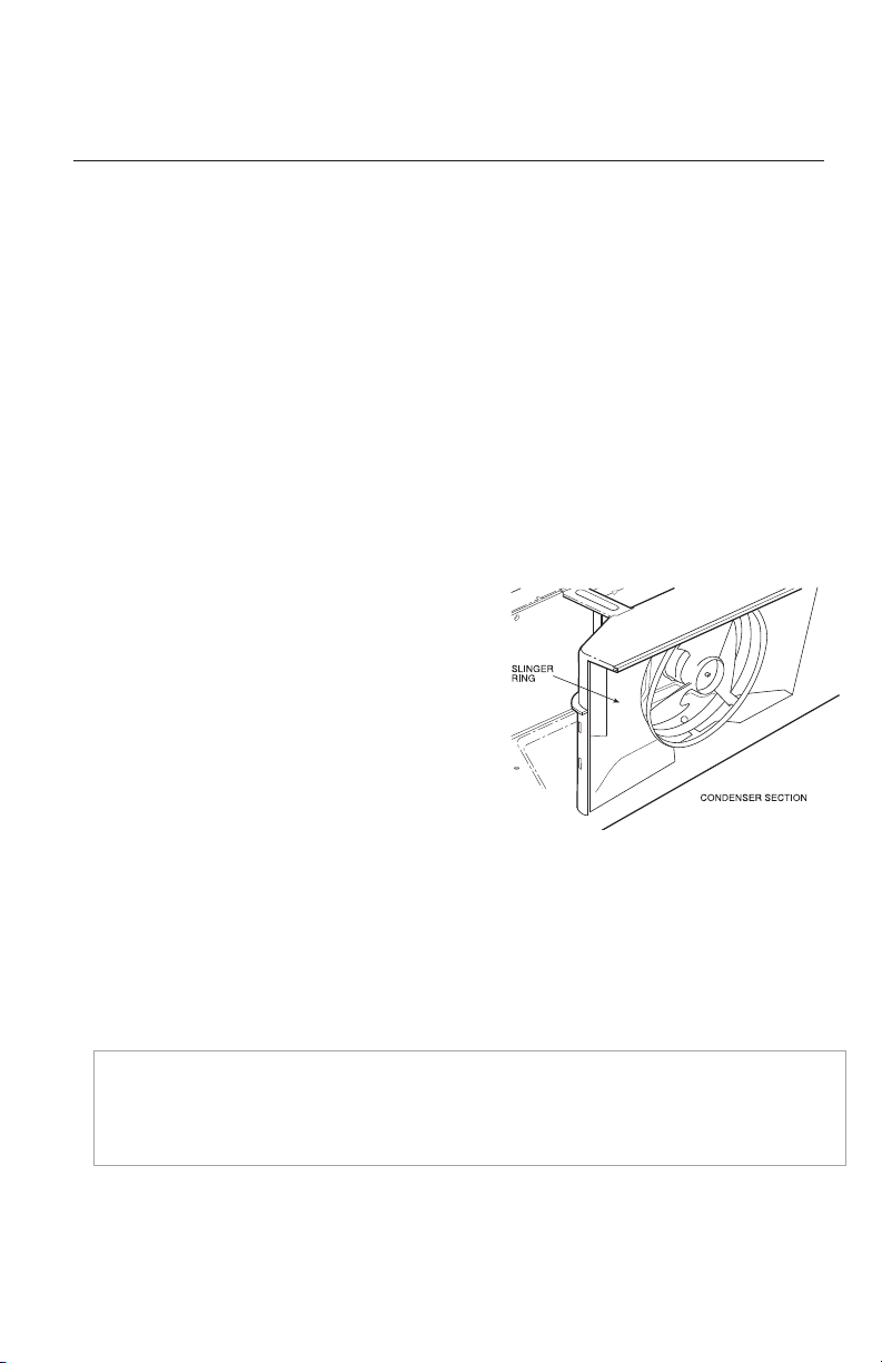
CONDENSATE REMOVAL SYSTEM
ETAC II has a new condensate (water) disposal
system. The outdoor fan prop has a built in slinger
ring which draws condensate water and sprays
it on the warm outdoor coil for evaporation.
Thus
providing better disposal of excess condensate
and
improving unit operating efficiency.
It is normal and desirable to have some condensate
water in the base pan to boost operating efficiency.
All heat pump units contain a condensate drain valve. This temperature activated drain valve opens
when the outdoor temperature drops below 55°F (12.8°C) to prevent water from freezing in the
base pan. The water drains from the unit though the wall sleeve and out the wall sleeve’s rear
condensate drainage holes. If the condensate drain kit accessory is attached to the wall sleeve,
water will drain through the condensate drain tube.
NOTE: This unit will not always evaporate 100% of the unit generated condensate and
blown in rain water. If it is necessary to control 100% of the condensate, the Drain Kit
(Part No.: DRAIN-KIT-1PK) and a building condensate drain system is recommended.
Fig. 2

ALL UNITS
WIRE SIZE
Use recommended wire size given in Table 1 and install on a single branch circuit. All wiring must
comply with local and national codes.
All units are designed to operate off ONE single
branch circuit only.
ELECTRICAL DATA
ELECTRICAL SHOCK HAZARD – Failure to follow this warning could result in personal
injury or death and/or property damage. DO NOT use an extension cord.
POWER CONNECTION OPTIONS
The appropriate power cord accessory kit is determined by the voltage, and amperage of the branch
circuit. The unit does not come with a power cord (or hard wire kit). An accessory power cord kit must
be installed on the unit. If the unit is to be hard wired, an accessory hard wire kit must be ordered.
Be sure that your outlet matches the appropriate blade configuration of the plug and that it is
within reach of the service cord. All wiring, including installation of the receptacle, must be in
accordance with the NEC and local codes, ordinances and regulations. National codes require the
use of an arc fault or leakage current detection device on all 208/230V power cords. Be sure to
select the correct cord for your installation.
IMPORTANT: For 265V units, the power cord is only 18 inches long and must plug
into the accessory electrical 265V subbase.
WARNING
CAUTION
WARNING
WARNING
EQUIPMENT DAMAGE HAZARD – Failure to follow this caution may result in equipment
damage or improper operation. Using a 30 amp cord on 7000 or 9000 BtuH models could
result in damage to the unit. For these models, use 15 or 20 amp power cords only.
WARNING
CAUTION
WARNING
CAUTION
NOTE: Use copper conductors only.
76
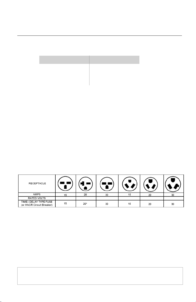
Table 2 – RECEPTACLES AND FUSE TYPES
ELECTRICAL DATA
Nameplate Amps AWG Wire Size †
7.0 to 12 14
12.1 to 16 12
16.1 to 24 10
Table 1 – SUGGESTED BRANCH CIRCUIT WIRE SIZES*
LEGEND
A
WG – American Wire Gauge
* Single circuit main power wire
f
rom electrical panel to unit.
AWG based on 240VAC Single
Phase, 100 ft. distance 1-way,
max. 5% allowable voltage drop.
GROUNDING
For safety and protection, the unit is grounded through the power cord plug or through separate
ground wire provided on hard wired units. Be sure that the branch circuit or general purpose
outlet is grounded.
VOLTAGE SUPPLY
Check voltage supply at outlet. For satisfactory results, the voltage range must always be within
the ranges found on the data information plate.
PROPER WALL RECEPTACLE OUTLET
The unit plug configuration must match the electrical wall outlet and be within reach of the
service cord. The standard cord – connected 265v units require an accessory electrical subbase.
Refer to Table 2 for proper receptacle and fuse type.
POWER CORD PROTECTION
The power cord for 208/230v units provide power cord safety protection. Unit power automatically
disconnects when unsafe conditions are detected. Power to the unit can be restored by pressing
the RESET button on LCDI plug head.
Upon completion of unit installation for 208/230V models, an operational check should be
performed using the TEST/RESET buttons on the plug head.
N
O
T
E
:
T
h
e
2
6
5
v
m
o
d
e
l
s
d
o
n
o
t
i
n
c
o
r
p
o
r
a
t
e
t
h
i
s
f
e
a
t
u
r
e
a
s
t
h
e
y
r
e
q
u
i
r
e
u
s
e
o
f
t
h
e
e
l
e
c
t
r
i
c
a
l
s
u
b
b
a
s
e
r
e
c
e
p
t
a
c
l
e
a
c
c
e
s
s
o
r
y
.
208/230 208/230 208/230 265 265 265
8
LEGEND
HACR-Heating,AirConditioning,Refrigeration
*Maybeusedfor15-ampapplications.
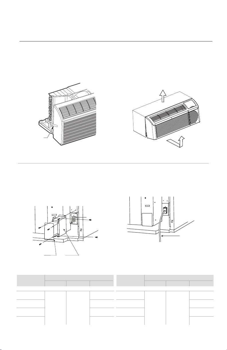
INSTALLATION
CHASSIS INSTALLATION
Units are shipped without a sleeve. In applications where unit is a replacement, it is recommended
that a standard wall sleeve be used.
These units can retrofit Carrier, General Electric, Amana, Trane, and Friedrich sleeves/grilles (be sure
outdoor grille is installed on the sleeve). See Table 3 for details. Gree engineering must approve any
other retrofit application.
For competitive retrofit applications, be sure that the foam seals (factory-installed on the tube
sheets) provide a good seal between the grille and outdoor coil. These foam seals provide
a barrier to separate outdoor coil discharge air from mixing with the outdoor
incoming air (known as air recirculation). Baffles may be required when using
non-Gree grills.
WARNING
CAUTION
WARNING
CAUTION
98
PROPER INSTALLATION IS THE RESPONSIBILITY OF THE INSTALLER. Product failure
due to improper installation is not covered under the limited Product Warranty.
WARNING
CAUTION
WARNING
WARNING
PERSONAL INJURY HAZARD – Failure to follow this warning could result in personal
injury or death. Chassis weighs up to 150 pounds (68.0kg). Seek help when lifting unit.
Lift unit by holding unit basepan.
UNIT DAMAGE AND/OR OPERATION HAZARD.
Failure to follow this caution may result in
equipment damage or improper operation. For retrofit
applications, foam seals on outdoor coil
tube sheets must make a seal between the coil and the grille or loss of performance and
premature damage to the major components can result.
WARNING
CAUTION
WARNING
CAUTION
WARNING
CAUTION
WARNING
CAUTION
Unit must be stored/placed in the horizontal position for 3 hours prior to startup, otherwise
unit may not start.
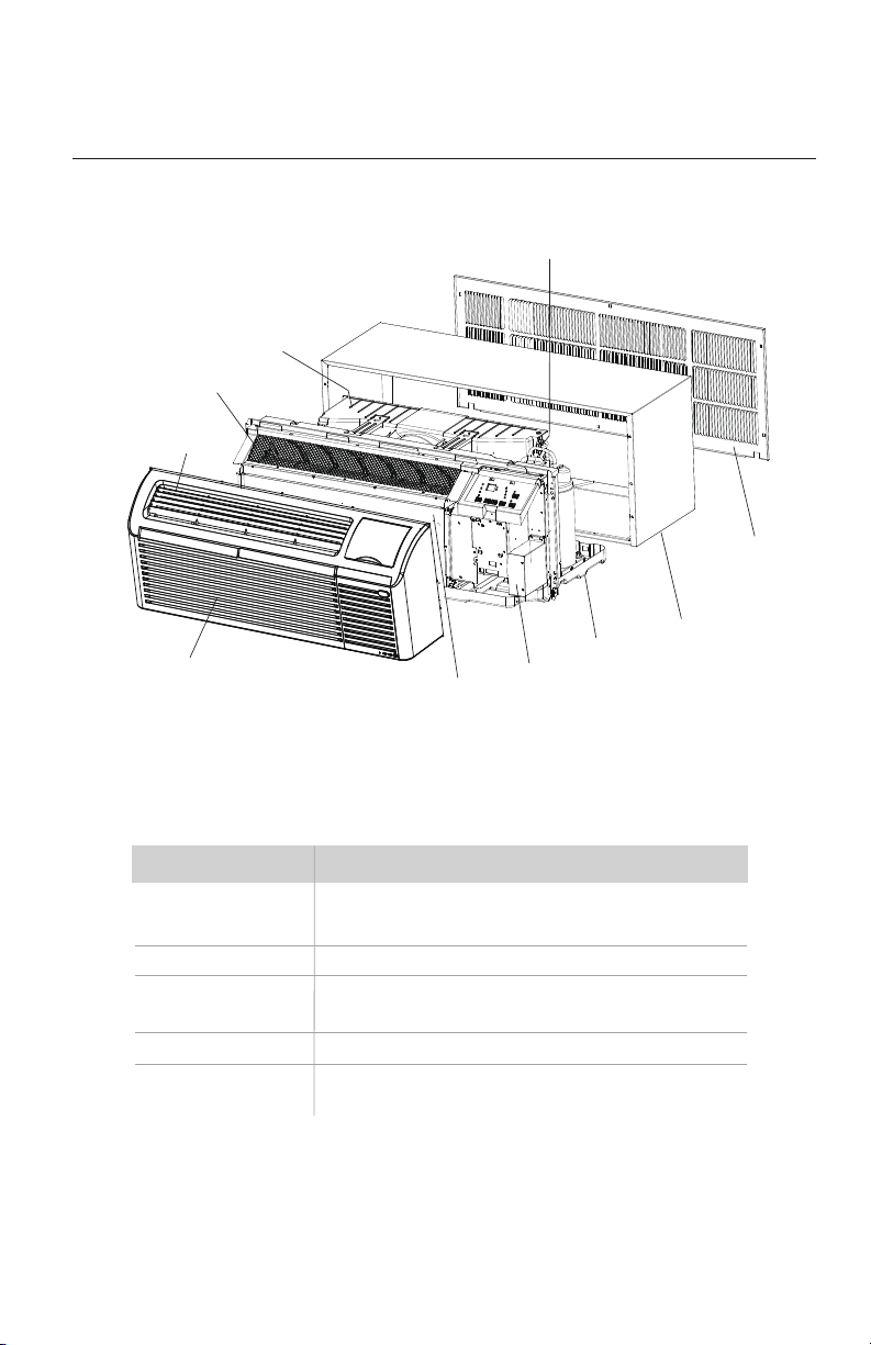
W
ire Screen
Discharge Grille
Front Panel
Indoor
Coil
O
utdoor Shroud
C
oil Tube Sheets
Accessory
Outdoor Grille
Accessory
Wall Sleeve
Basepan
Power Cord
Connection
INSTALLATION
Table 3 – RETROFIT WALL SLEEVES
Manufacturer Wall Sleeve Part Number
General Electric Metal Sleeve - RAB71
Plastic Sleeve - RAB77
Amana Metal Sleeve - WS900B
Gree Metal Sleeve - PTAC-SLEEVE-SE-INS
Plastic Sleeve - SLEEVE-INSUL-1PK
Trane Metal Sleeve - SLV149
Friedrich T-Series Metal 11 1/2-in. Deep Wall Sleeve
*
Standard Depth Wall Sleeve 16 x 42 x 13 3/4-in. PXWS
*FR-Sleeve-EXT accessory is required for retrofit into Friedrich (T-Series) wall sleeves.
Minimum wall sleeve opening must be greater than 14.75” x 40.0”.
10
Fig. 3 –
Unit Components
INSTALLATION
RETROFIT SLEEVE PREPARATION
IMPORTANT: Inspect wall sleeve thoroughly prior to installation. Manufacturer
does not assume responsibility for costs or damages due to defects in sleeve or
for improper installation.
ELECTRICAL SHOCK HAZARD – Failure to follow this warning could result in personal injury
or death. Disconnect all power to unit to avoid possible electrical shock during installation.
WARNING
CAUTION
WARNING
WARNING
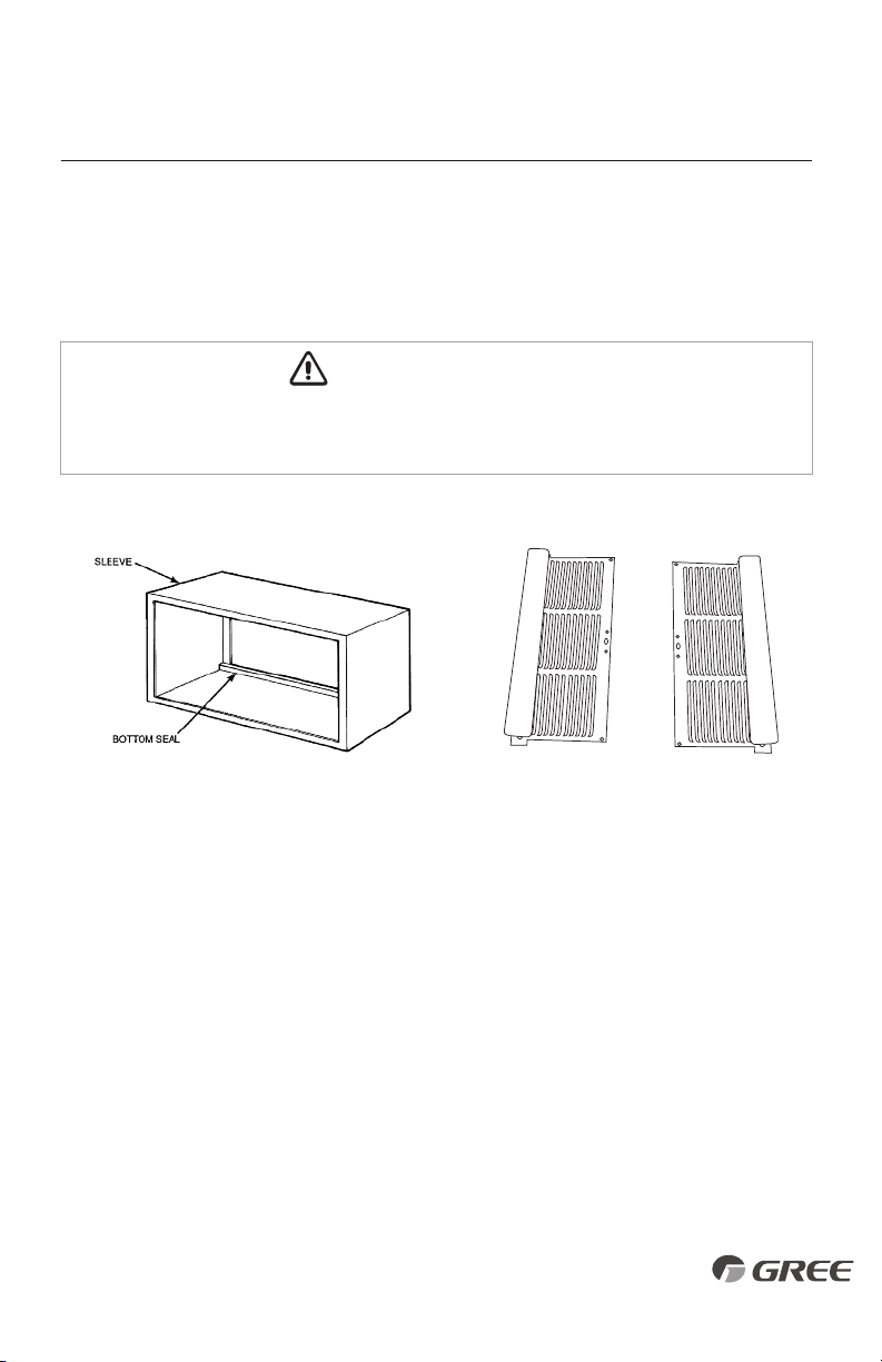
Fig. 4 – GE Plastic Sleeve
Remove bottom seal from plastic sleeve.
Fig. 5 – Accessory Baffle Kit
(Part# BAFFLE-KIT-1PK)
WINDOW WALL INSTALLATIONS
This application has become more common due to pre-manufactured windows with built-in
grilles. Installations using a grille built in a pre-manufactured window assembly may require
installation of an Accessory Baffle Kit (see Fig. 5), which ensures a good air seal between the
outdoor coil and exterior grille to prevent air recirculation. Air recirculation is a large contributor
to capacity loss and premature damage to major components.
1110
INSTALLATION
SHIPPING
TAPE
REMOVE SHIPPING
SCREW IF PRESENT
CHASSIS AND POWER CORD INSTALLATION PREPARATION
1. Carefully remove shipping tape from the
front panel.
Fig. 6
Fig. 9
Fig. 7
Fig. 8
2. Remove front panel.
a. Pull out at the bottom to release it from the tabs (1).
b. Then lift up (2).
Unit Connector
Junction Box Cover
Junction Box
Accessory
Power Supply Cord
2
1
3. Remove junction box.
a. Remove junction box cover by removing three
screws from front (save these for later).
b. Remove junction box by taking out top, rear and
side screws (save these for later).
Unit Connector
Junction Box Cover
Junction Box
Accessory
Power Supply Cord
4. Connect power cord connector to unit connector.
a. Units must be installed using the appropriate
power cord kit. See Power Connection Chart below.
Unit Connector
Junction Box Cover
Junction Box
Accessory
Power Supply Cord
Accessory
Power Cord
Unit Model
ETAC2-07HC265VA-A
ETAC2-09HC265VA-A
ETAC2-12HC265VA-A
ETAC2-15HC265VA-A
ETAC2-07HP265VA-A
ETAC2-09HP265VA-A
ETAC2-12HP265VA-A
ETAC2-15HP265VA-A
Electric Heater - Amp (KW)
20A (3.5KW)
265 VOLTS
E2CORD-
265V20A
15A (2.5KW)
E2CORD-
265V15A
30A (5.0KW)
Not available
*
E2CORD-
265V30A
Not available
*
E2CORD-
265V30A
Unit Model
ETAC2-07HC230VA-A
ETAC2-09HC230VA-A
ETAC2-12HC230VA-A
ETAC2-15HC230VA-A
ETAC2-07HP230VA-A
ETAC2-09HP230VA-A
ETAC2-12HP230VA-A
ETAC2-15HP230VA-A
POWER CONNECTION CHART
Electric Heater - Amp (KW)
20A (3.5KW)
230/208 VOLTS
E2CORD-
230V20A
15A (2.5KW)
E2CORD-
230V15A
30A (5.0KW)
Not available
*
E2CORD-
230V30A
Not available
*
E2CORD-
230V30A
* Using 30A on these units could result in damage to your unit.
12

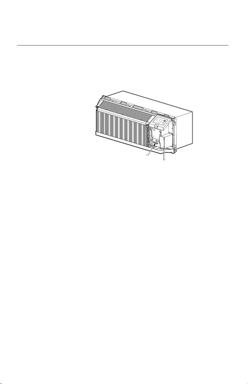
INSTALLATION
6.
Lift unit level and slide into wall sleeve until seal
rests firmly against front of wall sleeve.
a.
Secure with 4 mounting screws provided with the unit.
b.
Careful not to over tighten and strip the screws.
Fig. 11
5.
Re-install junction box and cover. Secure power cord.
a. Re-install junction box.
b. Use wire clamp to secure power cord to basepan
with screw provided.
c. Replace junction box cover.
Wire clamp
Fig. 10
7. Replace front panel.
a. Place tabs over top rail (1).
b. Push Inward at bottom until panel snaps into place (2).
c.
Plug unit in and turn power on.
Wire clamp
2
1
Fig. 12
1312
Power
Supply
Cord
Wire Clamp

SYSTEM CONFIGURATION
VENTILATION CONTROL
The unique ventilation system is activated by a two
position control. Fresh outside air is redirected by
the vent door to the indoor room. A polymer air filter
prevents dirt and debris from entering the room from
outdoors. The ventilation control lever is located at
left side of unit, behind the front panel.
NOTE: The vent door is screwed shut for shipping
purposes. Remove shipping screw before using vent
control lever. See Installation Instructions.
When vent is set at CLOSE, only the air inside the room
is circulated and filtered.
When vent is set at OPEN, some outdoor air will be drawn
into room. This will reduce heating or cooling efficiency.
ADJUSTING AIR DIRECTION
The bi-directional discharge grille is constructed of durable polycarbonate and is reversible. Air flows
upward at a 40 degree angle to the floor but can easily be adjusted to an 80 degree angle to the floor.
To adjust air direction:
1. Remove front panel.
2. Remove louver screws that
hold louver insert in place
(from back side of front panel).
3. Turn louver insert and rotate 180°.
4. Replace louver insert.
5. Replace screws and front panel.
WARNING
CAUTION
WARNING
CAUTION
UNIT DAMAGE HAZARD – Failure to follow this
caution may result in equipment damage or improper
operation. Failure to remove shipping tape and
screw will prevent fresh air vent door from opening
and may result in damage to vent door cable.
SHIPPING
TAP E
REMOVE SHIPPING
SCREW IF PRESENT
SHIPPING
TAP E
REMOVE SHIPPING
SCREW IF PRESENT
V
ent Control (Pull
lever through label
t
o operate.)
Louver screws
Louver screws
Air discharge upward
Air discharge outward (Default)
Adjusting Louvers
V
ent Control (Pull
lever through label
t
o operate.)
Louver screws
Louver screws
Air discharge upward
Air discharge outward (Default)
Adjusting Louvers
Fig. 14 – Ventilation Control
V
ent Control (Pull
lever through label
t
o operate.)
Louver screws
Louver screws
Air discharge upward
Air discharge outward (Default)
Adjusting Louvers
Fig. 15 – Backside of Front Panel
Fig. 16 – Adjusting Louvers
14
Vent Control (Pull
l
ever through label
to operate.)
Louver screws
Louver screws
Air discharge upward
Air discharge outward (Default)
Adjusting Louvers
Fig. 13 – Shipping Screw Removal
Vent Control (Pull
l
ever through label
to operate.)
Louver screws
Louver screws
Air discharge upward
Air discharge outward (Default)
Adjusting Louvers
DIGITAL CONTROL USER INPUT CONFIGURATION
The adjustable control dip switches are located at the lower portion of the control box.
The inputs are only visible and accessible with the front cover removed from the PTAC.
DIP SWITCH SETTING
• Emergency Heat Override – Switch 1
In the unlikely event of a compressor failure a heat pump unit maybe switched to operate in
only the electric heat mode until repairs can be made. Move Dip Switch 1 up to ‘ON’.
• Wall Thermostat – Switch
2
To enable wall thermostat control and disable the keypad, move Dip Switch 2 up to 'ON’.
• Heating Fan Control – Switch 3
Set indoor fan to continuous mode with Dip Switch 3 up or cycle mode with Dip Switch 3
down (factory default).
• Cooling Fan Control – Switch 4
Set indoor fan to cycle mode with Dip Switch 4 up or continuous mode with Dip Switch 4
down (factory default).
• Electronic Temperature Limiting – Switches 5-6
The factory default temperature range is 65°F to 78°F. Three other temperature ranges may
be selected with the Dip Switches. See Table 4 for available ranges.
• Room Freeze Protection – Switch 7
Room Freeze Protection can be switched off at the owner’s preference by moving Dip Switch 7 up
to ‘OFF’. This feature will monitor the indoor room conditions and in the event that the room
falls below 40°F the unit will cycle on high fan with the electric heater. This occurs regardless
of mode. Units are shipped from the factory with the room freeze protection enabled.
SYSTEM CONFIGURATION
Fig. 17 – Dip Switch Location
1514
Location of
Dip Switches
on Unit
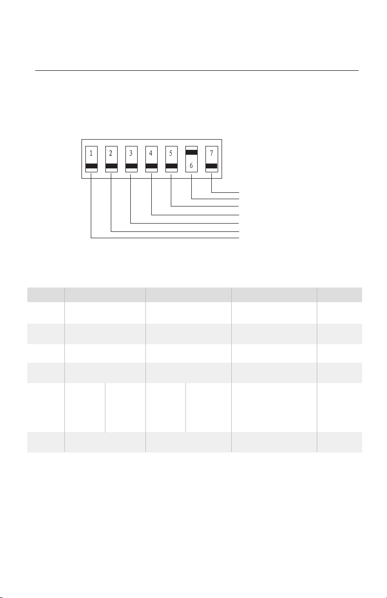
SYSTEM CONFIGURATION
DIP SWITCH CONFIGURATION
Freeze Guard
Setpoint Limit 1
Setpoint Limit 2
Fan CON/CYC for cooling
Fan CON/CYC for heating
Wall Thermostat Enable
Electric Heat Only (for heat pumps)
UP
DOWN
Table 4 – Dip Switch Functions
Fig. 18 – Dip Switches
Up
Electric Heat Only
Wall Thermostat Enable
Fan Continuous Run for Heating
Fan Cycle for Cooling
UP*UP
68-75°F
20-24°C
Freeze Guard Disable
UP*DOWN
63-80°F
18-28°C
DOWN*DOWN
61-86°F
16-30°C
(full range)
DOWN*UP
65-78°F
19-26°C
Down
Heat Pump
Control Panel Enable
Fan Cycle for Heat
Fan Continuous Run for Cooling
DOWN*UP
65-78°F
19-26°C
Freeze Guard Enable
Remarks
For Heat Pump Unit Only
Two configurations (5*6)
combine to select set point range.
When set point limit is set,
display always shows full range.
Default
DOWN
DOWN
DOWN
DOWN
DOWN
No.
1
2
3
4
5*6
7
16

SYSTEM CONFIGURATION
KEYPAD CONFIGURATION
Additional unit configurations are available using the keypad.
• To Enter Configuration Mode
Apply power to unit. Within 30 seconds press and hold the Fan Speed and Setpoint Down
button for 5 seconds.
• To scroll through the Keypad Configuration options
Press and release the Fan Speed button. The stored value will be displayed.
• To modify Configuration settings
Press and release the Setpoint Up or Setpoint Down buttons.
• To exit Keypad Configuration
Press MODE button on Keypad or wait 30 sec for automatic exit.
1. FAHRENHEIT/CELSIUS DISPLAY SWITCH
Use the Setpoint Up and Setpoint Down buttons to change between degrees
Fahrenheit (°F) and Celsius (°C) on the display. Default is Fahrenheit.
2. INDOOR AIR TEMPERATURE SENSOR BIASING FOR COOLING MODE
Sometimes known as an anticipator, the air temperature sensor bias is used to adjust the
room air temperature reading when in cooling mode. (Not normally required.) Default
biasing value is zero. Use the Setpoint Up and Setpoint Down buttons to set a bias
between -6°F to +6°F (-3°C to +3°C).
3. INDOOR AIR TEMPERATURE SENSOR BIASING FOR HEATING MODE
This operates the same as above, but for heating mode.
4. INDOOR TEMPERATURE DISPLAY
Use the Setpoint Up and Setpoint Down buttons to change between Setpoint Only
display (SP mode) and Room Temperature/Setpoint display (AA mode).
SP Mode
– Only the setpoint is displayed during heat, cool, and dry modes (factory default).
AA Mode
– The unit will display both setpoint and room temperature.
– Room temperature will be displayed in heat, cool, dry and fan only modes.
– Setpoint will be displayed for 10 seconds immediately after a mode change.
– Setpoint will be displayed for 10 seconds immediately after changing the setpoint.
1716
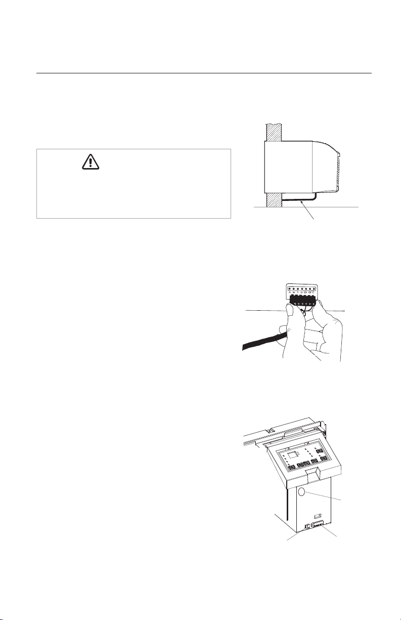
Thermostat Wire Routing
(under sleeve, behind front panel)
WALL THERMOSTAT INSTALLATION
ETAC II heat pump and heat/cool models will work with
most common 24vac single stage wall thermostats.
1. Disconnect all electrical power to unit including
disconnecting plug, fuses and circuit breakers.
2. Select a proper location on the wall for mounting
the wall thermostat
3. Install switch box (if required by code) and
thermostat back plate.
4. Install thermostat wire (field supplied) between
the thermostat and
ETAC II
. Unless otherwise
instructed, use standard 18-20AWG solid copper
thermostat wire.
5. Route thermostat wire beneath
ETAC II
unit and
up under the front panel on the power cord side
(see Fig. 19). Never route thermostat wire
through the wall sleeve.
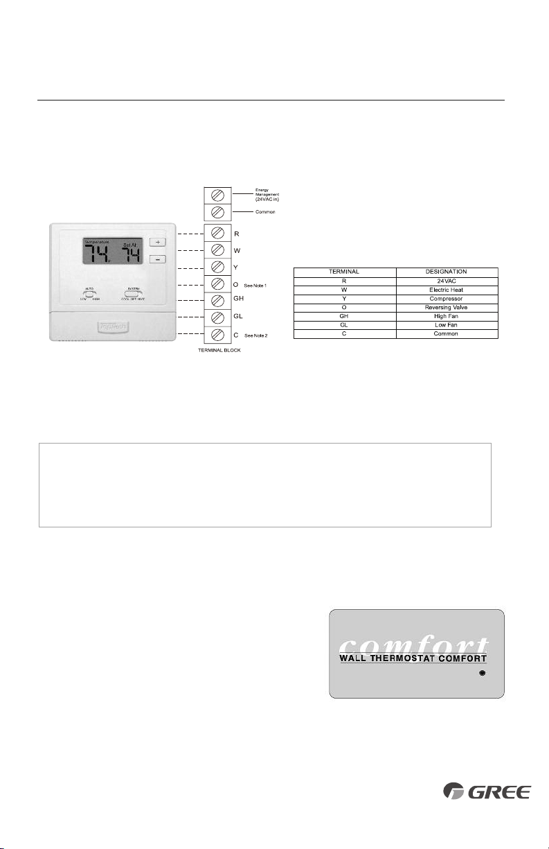
6. Locate thermostat connection terminal on
control box (see Fig. 21). Carefully remove
terminal block from unit (see Fig. 20).
STATUS LED
Wall Thermostat
Terminal Connections
Energy Management
Terminal Connections
SYSTEM CONFIGURATION
Fig. 19 – Proper Wire Routing
Fig. 20 – Terminal Connector
Removal and Replacement
Thermostat Wire Routing
(under sleeve, behind front panel)
Fig. 21 – Terminal Connector
and Status LED Location
ELECTRICAL SHOCK HAZARD – The unit and
accessories should be installed and serviced only by
trained, qualified installers and service technicians.
WARNING
CAUTION
WARNING
CAUTION
18
SYSTEM CONFIGURATION
Fig. 23 – Wall Thermostat
Control Panel Label
(Part# 62261101)
NOTE: For thermostats that have only one fan speed output (on or auto), the fan speed
is determined by how the terminal connector is wired. If Low fan is desired, wire the
G output from the thermostat to GL on the unit’s terminal block. If Hi fan is desired, wire
the G output from the thermostat to GH on the unit’s terminal block.
WALL THERMOSTAT INSTALLATION (CON’T)
7. Connect thermostat wire to the ETAC II thermostat connection terminals per wire diagram (see
Fig.
22).
8. Carefully re-attach thermostat terminal block on unit.
9. Locate configuration dip switches above thermostat
terminal connections. Set switch #2 "UP" for Wall
Thermostat Mode (see Fig. 17).
10.
Install thermostat escutcheon label over touchpad
control panel (see Fig. 23). Included in I/O packet.
11.
Mount, wire and configure wall thermostat
per instructions provided by the manufacturer.
12.
Restore power to unit and verify wall thermostat operation.
NOTES:
1. Use terminal “O” for heat pump connection only.
2. Terminal “C” (common) is typically only required
for digital thermostats.
NOTES:
Any illegal input combinations will be captured as thermostat
wiring failures and will light the STATUS LED indicator on main
board (see Intelligent Self-Checking Control section).
Fig. 22 – Wiring Connections
1918

INTELLIGENT SELF-CHECKING CONTROL
Your ETAC II has a computer on board that continuously checks key components of the unit to
ensure they are operating properly. Under normal operation, unit status indicator (STATUS, on
main PCB), light is steadily ON. If there is a major problem, the unit will shut down and display
a diagnostic failure code on the unit’s display. If it is only a minor failure and unit is correcting the
fault by itself, the diagnostic code will be flashed on the status LED that can easily be seen when
the front panel is removed (see Fig. 21). Failure STATUS codes are defined in the table below.
NOTE:
The ETAC II is operating normally when the Status LED continuously flashes ON for 1 second and OFF for 1 second.
SYSTEM CONFIGURATION
Table 5 – STATUS LED Indicator Definitions
ENERGY MANAGEMENT INPUT (FRONT DESK CONTROL)
The ETAC II can interface to a switch signal from remote energy management input, called EM
signal or front desk control. The input signal must be 24 VAC. If unit receives a 24 VAC signal, it
will turn off; otherwise, the unit runs normally. This function will be disabled under Freeze Guard
protection. See Fig. 21 for terminal connections.
Indoor air temp sensor open/short
Indoor coil sensor open or short
Outdoor coil sensor open/short
Freeze Guard protection
Indoor coil freeze protection
Outdoor coil high temp protection
Defrost (heat pump type)
Indoor coil high temp protection
Thermostat wiring error
High pressure protection (optional)
ETAC II Display ‘F1’, with STATUS light flash 1 times and off 3 sec, repeat
ETAC II Display ‘F2’, with STATUS light flash 2 times and off 3 sec, repeat
ETAC II Display ‘F4’, with STATUS light flash 3 times and off 3 sec, repeat
ETAC II Display ‘FP’
STATUS LED light flash 5 times and off 3 sec, repeat
STATUS LED light flash 6 times and off 3 sec, repeat
STATUS LED light flash 7 times and off 3 sec, repeat
STATUS LED light flash 8 times and off 3 sec, repeat
STATUS LED light flash 9 times and off 3 sec, repeat
ETAC II Display ‘E1’, (the highest display grade)
1
2
3
4
5
6
7
8
9
10
20
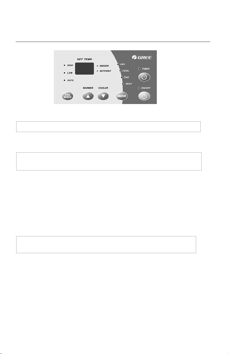
OPERATION
Fig. 24 – ETAC II
Display and Touchpad
ABOUT THE CONTROLS ON YOUR UNIT
NOTE: After power failure, unit automatically restores last programmed settings.
1. ON and OFF MODES
ON MODE – Places unit in ready or operation mode.
OFF MODE – Places unit in standby mode.
2. TEMP CONTROL
Temp Control is used to maintain room temperature. Compressor will cycle on and off to keep
room at the requested level of comfort.
COOLER – Lowers temperature. Minimum temperature setting is 61°F/16°C.
WARMER – Raises temperature. Maximum temperature setting is 86°F/30°C.
NOTE: The LED above the ON/OFF button will be green when unit is ON and red when the unit is
OFF. All other LEDs will be off when unit is set to OFF mode. Power remains connected to unit.
3. OPERATING MODE
MODE-COOL – For cooling
MODE-HEAT – For heating
MODE-DRY – For cooling with additional moisture removal.
MODE-FAN – For fan-only operation
4. FAN SPEED Set fan operation for HI, LO and AUTO speed.
Auto Fan Mode – Adjusts the indoor fan speed to balance comfort and quietness. Fan speed will
increase the farther away from the selected room temperature to quickly reach desired room temperature.
As the unit approaches selected temperature, the indoor fan slows down to a quieter comfort level.
5. TIMER MODE
Timer ON –When the unit is ON, the Timer ON function can be set. Time setting range is 0.5 to 24 hrs.
When the selected time is reached, the unit will turn ON and operate according to system settings.
Timer OFF – When the unit is OFF, the Timer OFF function can be set. Time setting range is 0.5 to 24 hrs.
When the selected time is reached, the unit will turn OFF.
Timer Setting – Press Timer button to set timer function. The Timer LED will turn ON and “88” will
be displayed. Press the up or down arrows to select the desired time.
NOTE: For heat pumps, raising the heat setting 5°F (2.8°C) will cause unit to use
electric heating elements for one cycle, to reach new requested temperature quickly.
20 21
CARE AND CLEANING
FRONT PANEL AND CASE
Turn unit off and disconnect power supply. To clean, use water and a mild detergent.
DO NOT use bleach or abrasives. Some commercial cleaners may damage the plastic parts.
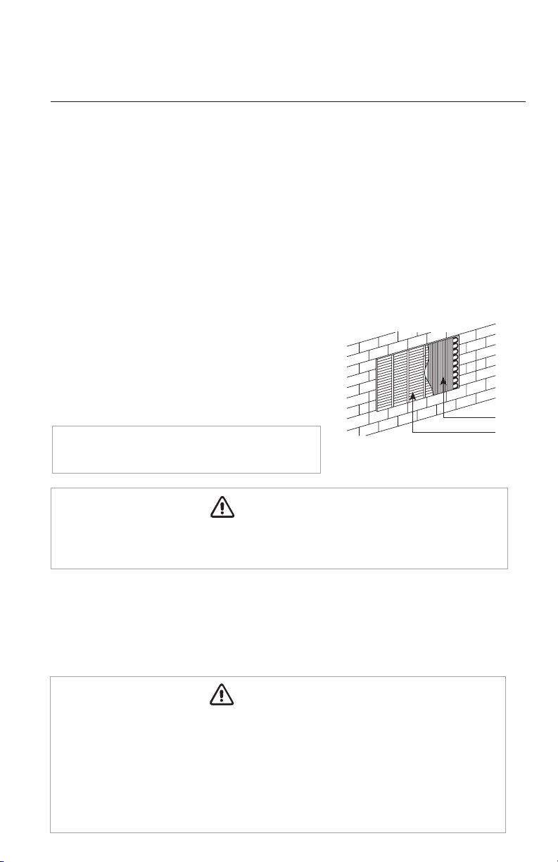
OUTDOOR COIL
Coil on outdoor side of unit should be checked regularly.
Unit will need to be removed from wall sleeve to inspect
dirt buildup that will occur on the inside of the coil. Clean
both sides of outdoor coil with warm water and a mild
detergent. Do not use corrosive coil cleaners.
BASEPAN
In some installations, dirt or other debris may be blown into unit from outside and settle in base
pan (bottom of unit). In some areas of the United States, a“jell-like” substance may be seen in
the basepan. Check basepan periodically and clean, if necessary.
NOTE: Never use a high-pressure spray on coil.
Clean inside and outside of outdoor coils regularly.
Fig. 25 – Outdoor Coil
WARNING
CAUTION
WARNING
CAUTION
UNIT DAMAGE HAZARD – Failure to follow this caution may result in equipment
damage or improper operation. Airflow restriction may cause damage to the unit.
WARNING
CAUTION
WARNING
CAUTION
UNIT DAMAGE HAZARD – Failure to follow this caution may result in equipment
damage or improper operation. Do not operate unit without filters in place. If a filter
becomes damaged, it should be replaced immediately.
Operating the unit without filters or with damaged filters will allow dirt and dust to
reach indoor coil and reduce cooling, heating, airflow and efficiency of unit. Airflow
restriction may cause damage to the unit; thereby voiding equipment warranty.
Preventive maintenance is essential to proper unit operation, efficiency and longevity, and
required to maintain equipment warranty.
To ensure equipment operates properly, it must be properly maintained. Equipment operation
should be checked and verified several times during each year. For typical unit inspection and
maintenance, follow the guidelines below:
22
2 Air filters
Pull up
Coils
Grille
Dirty filter-
Needs cleaning
Clogged filter -
Greatly reduces cooling,
heating and airflow.
Push down
2 Air filters
Pull up
Coils
Grille
Dirty filter-
Needs cleaning
Clogged filter -
Greatly reduces cooling,
heating and airflow.
Push down
2 Air filters
Pull up
Coils
Grille
Dirty filter-
Needs cleaning
Clogged filter -
Greatly reduces cooling,
heating and airflow.
Push down
CARE AND CLEANING
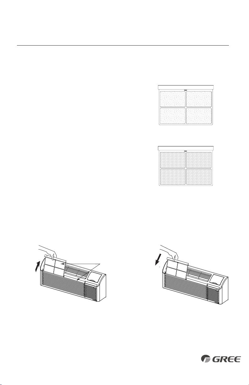
AIR FILTERS
IMPORTANT: Turn unit off before cleaning.
IDENTIFYING CLOGGED FILTER
The most important thing you can do to maintain unit
efficiency is to clean the filters at least every 30 days
(or sooner depending on application). Clogged filters
reduce cooling, heating and airflow.
2 Air filters
Pull up
Coils
G
rille
Dirty filter-
Needs cleaning
Clogged filter -
Greatly reduces cooling,
heating and airflow.
Push down
2 Air filters
Pull up
Coils
Grille
Dirty filter-
Needs cleaning
Clogged filter -
Greatly reduces cooling,
heating and airflow.
Push down
Fig. 26 – Identifying Clogged Filter
Fig. 27 – Removing and Replacing Air Filter
Keeping filters clean will:
• Decrease cost of operation.
• Save energy.
• Prevent clogged indoor coil.
• Reduce risk of premature component failure.
To Clean Air Filters:
• Vacuum off heavy soil.
• Run water through filters.
• Dry thoroughly before replacing.
Removing Air Filter Replacing Air Filter
2322

TROUBLESHOOTING
POSSIBLE CAUSES
UNIT DOES NOT START
• Unit may have become unplugged
• Fuse may have blown
• Circuit breaker may have been tripped
• Unit may be off or in wall thermostat mode. Check
section on dip switch settings to verify dip switches
are set properly.
• Unit may be in a protection or diagnostic failure mode.
See section on Intelligent Self-checking Control.
UNIT NOT COOLING/HEATING ROOM
• Unit air discharge section is blocked
• Temperature setting is not high or low enough.
Note: Setpoint limits may not allow the unit to
heat or cool the room to the temperature desired.
Check section on dip switch settings.
• Unit air filters are dirty.
• Room is excessively hot or cold when unit is started.
• Vent door left open
• Unit may be in a protection or diagnostic failure
mode
. Check section on Intelligent Self-checking
Control.
• Compressor is in time delay. There is a protective time
delay (approx. 3 minutes) on starting the compressor
after a power outage (or restarting after it has been
turned off), to prevent tripping of the compressor
overload.
DISPLAY HAS STRANGE
NUMBERS/CHARACTERS ON IT
UNIT MAKING NOISES
SOLUTIONS
• Check that plug is plugged securely in wall receptacle.
Note:
Plug has a test/reset button on it. Make sure that
the plug has not tripped.
• Replace the fuse. See Note 1.
• Reset circuit breaker. See Note 1.
• Turn unit on (bottom right button on keypad).
Note:
If the unit turns on, the LED will be green. If the
unit is off, the LED will be red. If there is no LED on, there
is a problem with power or damage to the control.
• Make sure that curtains, blinds or furniture are not
restricting or blocking unit airflow.
• Reset to a lower or higher temperature setting.
• Remove and clean filters.
• Allow sufficient amount of time for unit to heat or
cool the room. Start heating or cooling early before
outdoor temperature or gatherings of people make
room uncomfortable.
• Close vent door.
• Check dip switch settings for desired comfort.
Wait approximately 3 minutes for compressor to start.
• The unit may be in a diagnostic condition. Check
Intelligent Self Checking Control section to determine
if unit has had a failure.
• The unit may be set for °C (instead of °F), see the
keypad configuration section.
• Clicking, gurgling and whooshing noises are normal
during operation of unit.
24

TROUBLESHOOTING
POSSIBLE CAUSES
WATER DRIPPING INSIDE
• Wall sleeve is not installed level
• Clogged drain
ICE OR FROST FORMS ON INDOOR COIL
• Low outdoor temperature
• Dirty filters
COMPRESSOR PROTECTION
• Power may have cycled, so compressor is in a restart
protection.
WALL THERMOSTAT PROBLEM
SOLUTIONS
• Wall sleeve must be installed with a 1/4 bubble pitch
toward the outside for proper drainage of condensation.
Check that installation is level and make any necessary
adjustments.
• The condensate drain may be partially or fully plugged.
• When outdoor temperature is approximately 55°F
(12.8°C) or below, frost may form on the indoor coil
when unit is in Cooling mode. Switch unit to FAN
operation until ice or frost melts.
• Remove and clean filters.
• Random Compressor restart – Whenever the unit
is plugged in, or power has been restarted, a random
compressor restart will occur. After a power outage, the
compressor will restart after approximately 3 minutes.
• Compressor Protection – To prevent short cycling
of the compressor, there is a random start up delay
of 3 minutes and a minimum compressor run time of
3 minutes.
• Verify wiring is correct between thermostat and unit.
• Dip Switch settings are only read during power up.
Unplug unit and verify Dip Switch Settings, then plug
unit in.
NOTES:
1. If circuit breaker is tripped or fuse is blown more than once, contact a qualified electrician.
2. If unit is installed where condensation drainage could drip in an undesirable location, an accessory drain kit should be installed
and connected to drain system.
2524

GREE ELECTRIC APPLIANCES, INC.
www.greecomfort.com
LIMITED WARRANTY
TWO-YEAR PARTS AND LABOR LIMITED WARRANTY
–
During the first two years after purchase, GREE will, through its authorized independent servicing dealer or
service stations*, and free of charge to the user or subsequent users, repair or replace any parts that fail due to defect in material or workmanship. The replacement
p
art can be a new or remanufactured part as provided at GREE’S sole option.
EXTENDED THREE-YEAR PARTS AND LABOR LIMITED WARRANTY ON SEALED REFRIGERATION SYSTEM ONLY
–
During the third through fifth years after date
of original purchase, GREE will, through its authorized servicing dealers and service stations* and free of charge to the end user or subsequent users, remove, repair
or replace the compressor, condenser, evaporator or connecting tubing if it failed due to defect in material or workmanship. This includes system refrigeration charge.
The replacement part can be new or a remanufactured part at GREE’S sole option.
EXTENDED THREE-YEAR PARTS ONLY LIMITED WARRANTY ON NON-SEALED REFRIGERATION SYSTEM ONLY
– During the third through fifth years after
date of original purchase, Gree will provide, through its authorized servicing dealers and service stations and free of charge to the end user or subsequent users,
any non-sealed system part (motor, solenoid, thermistor, circuit boards, relays, switch, capacitor, overload, drain valve, fan, stator) if failed due to defect in material
or workmanship. The replacement part can be new or a remanufactured part at GREE’S sole option. THIS LIMITED WARRANTY DOES NOT INCLUDE LABOR, user is
responsible for labor, including cost of diagnosis of problem, removal and transportation of the air conditioner to and from the service center, and reinstallation
charges necessary to accomplish repair.
LIMITATION OF WARRANTIES
– ALL IMPLIED WARRANTIES (INCLUDING IMPLIED WARRANTIES OF MERCHANTABILITY AND FITNESS FOR PARTICULAR USE
OR PURPOSE) ARE HEREBY LIMITED IN DURATION TO THE PERIOD FOR WHICH EACH LIMITED WARRANTY IS GIVEN AND APPLIES. SOME STATES DO NOT ALLOW
LIMITATIONS ON HOW LONG AN IMPLIED WARRANTY LASTS, SO THE ABOVE LIMITATION MAY NOT APPLY TO YOU. THE EXPRESSED WARRANTIES MADE IN
THIS WARRANTY ARE EXCLUSIVE AND MAY NOT BE ALTERED, ENLARGED, OR CHANGED BY ANY DISTRIBUTOR, DEALER, OR OTHER PERSON WHATSOEVER.
ALL WORK UNDER THE TERMS OF THIS WARRANTY SHALL BE PERFORMED DURING NORMAL WORKING HOURS. ALL REPLACEMENT PARTS, WHETHER
NEW OR REMANUFACTURED, ASSUME AS THEIR WARRANTY PERIOD ONLY THE REMAINING TIME PERIOD OF THIS WARRANTY.
ALL WORK UNDER THE TERMS OF THIS WARRANTY SHALL BE PERFORMED DURING NORMAL WORKING HOURS. ALL REPLACEMENT PARTS, WHETHER
NEW OR REMANUFACTURED, ASSUME AS THEIR WARRANTY PERIOD ONLY THE REMAINING TIME PERIOD OF THIS WARRANTY.
GREE WILL NOT BE RESPONSIBLE FOR:
1. CLEANING REQUIRED PRIOR TO WARRANTY REPAIR.
2. Standard maintenance, cleaning or damage resulting from failure to perform normal maintenance as outlined in the owner’s manual.
3. Instruction on methods of control and use of air conditioning unit after initial installation.
4. Damage or repairs needed as consequence of faulty installation or application. This is the responsibility of the installer.
5. Failure to start due to voltage conditions, blown fuses, open circuit breakers or any other damages due to the inadequacy or interruption of electrical services.
6. Damage or repairs needed as consequence of any misapplication, abuse, unauthorized alteration, improper servicing or operation.
7. Damage as a result of floods, winds, fires, lightning, accidents, corrosive environment, or other conditions beyond the control of GREE.
EXCEPTION TO CORROSIVE ENVIRONMENT EXCLUSION IN ABOVE PARAGRAPH – Packaged terminal units built with corrosion protection are exempt from the
exclusion –“Corrosive Environment.” The unit model number is identified on the nameplate with CP suffix.
8. Reimbursement for replacement parts or repair services which are not supplied or designated by GREE and which are specifically covered under this warranty.
9. GREE products installed outside the continental U.S.A., Alaska, Hawaii, and Canada.
10. Shipping damage or damage as a result of transporting the unit. This is the responsibility of the selling dealer or the authorized service station.
11. ANY SPECIAL, INDIRECT OR CONSEQUENTIAL PROPERTY OR COMMERCIAL DAMAGE OF ANY NATURE WHATSOEVER. Some states do not allow the exclusion
or limitation of incidental or consequential damages, so the above limitation or exclusion may not apply to you.
12. Warranty coverage of accessory items (wall thermostats, wall sleeves, etc.)
13. Installations of non-corrosion protected models within one (1) mile of a corrosive body of water or environment shall void the EXTENDED THREE-YEAR PARTS
AND LABOR LIMITED WARRANTY ON SEALED REFRIGERATION SYSTEM ONLY and EXTENDED THREE-YEAR PARTS ONLY LIMITED WARRANTY ON NON-SEALED
REFRIGERATION SYSTEM ONLY limited warranties .
* Authorized independent dealers or service stations are registered with Gree through its distributor organization.
This warranty gives you specific legal rights, and you may also have other rights which vary from state to state.
IF YOUR AIR CONDITIONER DOES NOT WORK, FOLLOW THESE STEPS IN ORDER:
1. CHECK THE THINGS YOU CAN DO YOURSELF. These include being sure the air conditioner is plugged in firmly in an appropriate receptacle, checking the fuse
or circuit breaker and ensuring its replacement or resetting, if necessary, and rereading the instruction book to ensure that all controls are set properly. By doing
this you can save money. Many unnecessary service calls result in the serviceman doing what the owner can do for him or herself.
2. CONTACT YOUR DEALER OR THE AUTHORIZED SERVICE CENTER HE RECOMMENDS. They have been set up to handle the great majority of all possible service
problems. The quickest, surest and best way to get your air conditioner back in service is to use this step before proceeding further.
Gree Electric Appliances, Inc ©2016 Printed in U.S.A. Edition Date: 01/16 Catalog No. PTAC-ETAC II-1SI
Manufacturer reserves the right to change, at any time, specifications and designs without notice and without obligations.