
Universal™ Series
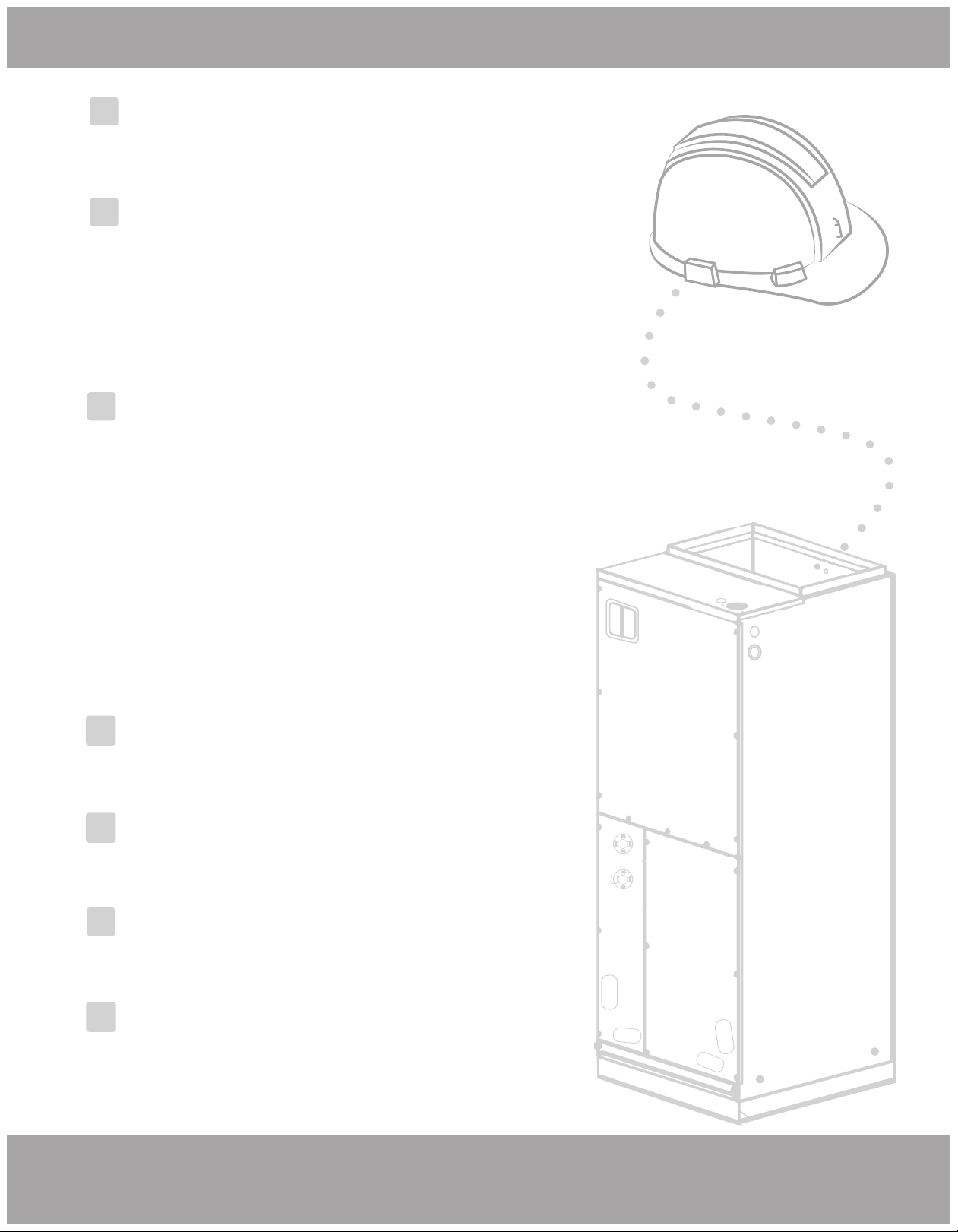
Air Handler | 2-3 Ton
Please read this manual carefully before installation and keep it for future reference.
Copyright © 2019 MRCOOL, LLC | v1.10.20
Thank you for choosing MRCOOL. Please read this manual carefully before installation and keep it for future reference.
Owner’s Manual
Contents
Page 1 mrcool.com
EU Disposal Guidelines .............. 29
6
Post Installation Checks ........... 22
3
Troubleshooting ......................... 24
4
Maintenance and Care
................
28
5
Unit Installation ........................... 9
1. Pre-Installation Instructions............................ 9
3. Conventional Line Set Installation................ 11
3. No-Vac® Quick Connect ® Installation....... 12
4. Condensate Removal ..................................... 13
2. Installation Location ....................................... 10
6. Electric Heater .................................................. 14
7 Air Handler Field Conversion ........................ 16
8. Electrical Connection ...................................... 17
5. Ductwork ............................................................ 14
2
1. Introduction ........................................................ 5
2. Accessories ........................................................ 6
4. Main Parts ........................................................... 8
1
Appliance Overview ..................... 5
Safety Precautions ....................... 2
!
3. Unit Dimensions ................................................ 7
Page 2
Safety Precautions
mrcool.com
WARNING
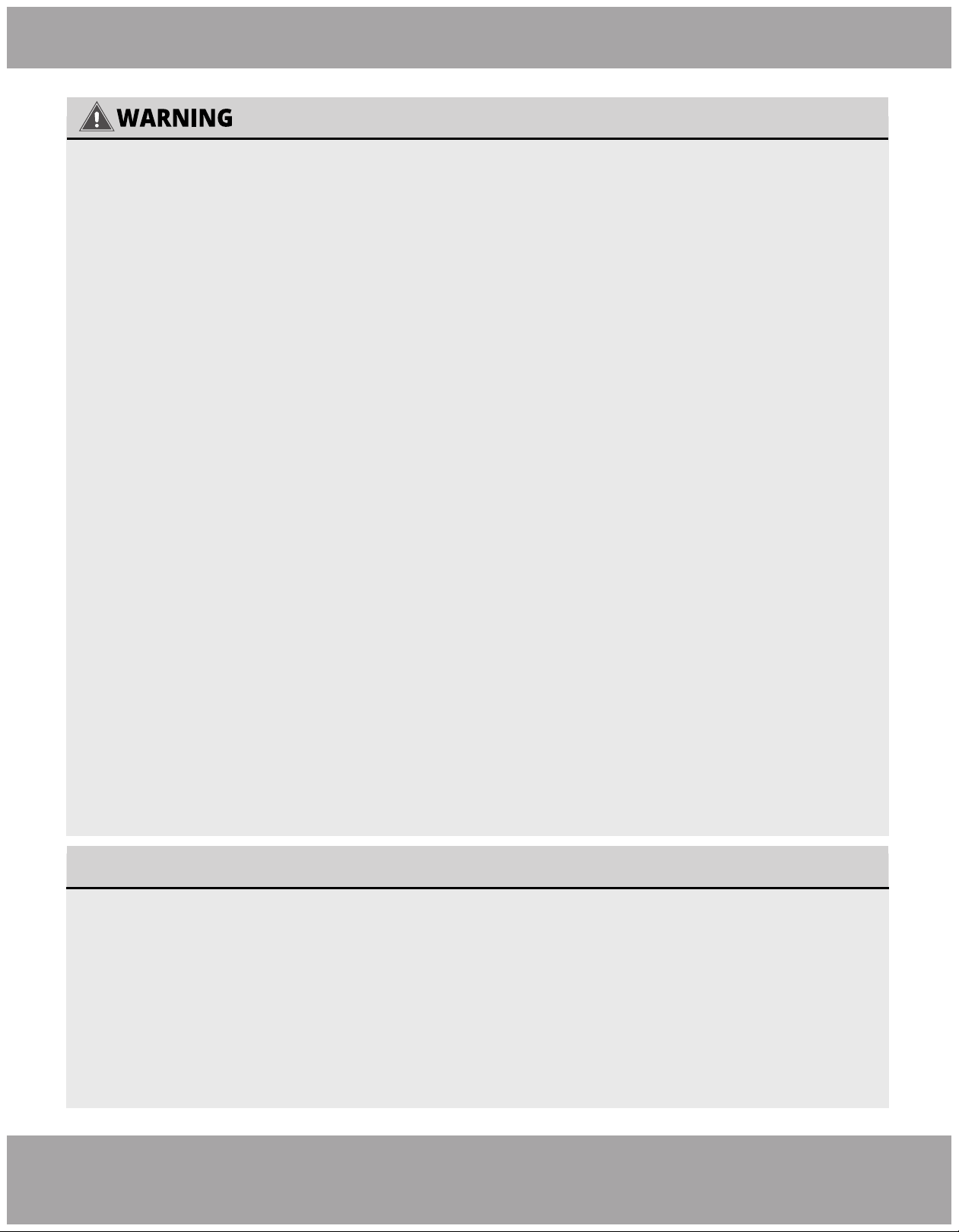
Please read the manual in its entirety before installing, operating or repairing.
DO NOT share the electrical circuit with other appliances. Improper or insufficient power supply
can cause fire or electrical shock.
When connecting refrigerant piping,
DO NOT let substances or gases other than the refrigerant
enter the unit. The presence of other gases or substances will lower the unit’s capacity, and may
cause abnormally high pressure in the operation cycle. This may cause explosion and injury.
DO NOT connect the ground wire to a gas pipe, water pipe, lightning arrester or telephone wire.
DO NOT allow children to play with the air conditioner. Children should be supervised around the
unit at all times.
DO NOT alter the settings of the pressure sensor or other protective devices; if short-circuited or
modified, fire or even an explosion could occur.
Installation must be performed by an authorized technician. Improper installation may cause
water leakage, electrical shock, or fire.
Installation must be performed according to installation instructions. Improper installation may
cause water leakage, electrical shock, or fire.
In North America, installation must be performed in accordance with the requirement of NEC and
CEC (by authorized personnel only.) Contact an authorized service technician for repair or
maintenance of the unit.
Only use the included accessories and specified parts for installation. Using non-standard parts
can cause water leakage, electrical shock, or fire and may cause the unit to fail.
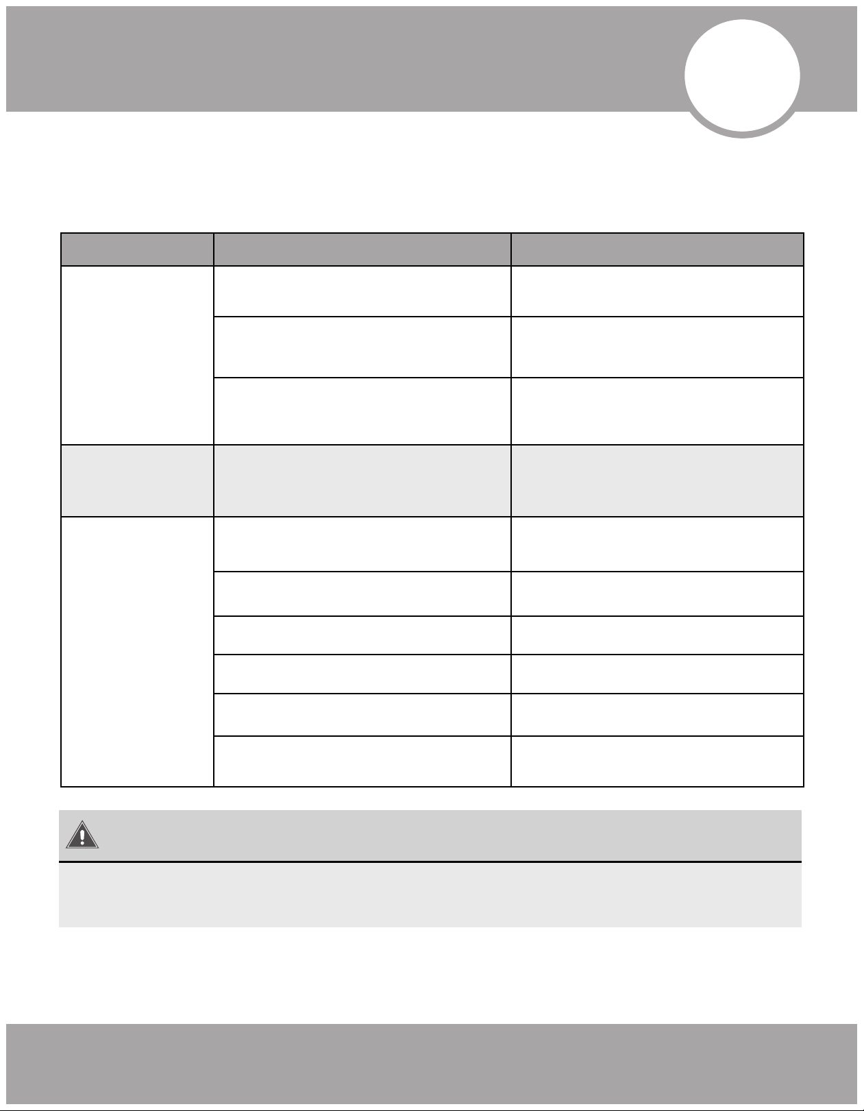
Read Before Installation
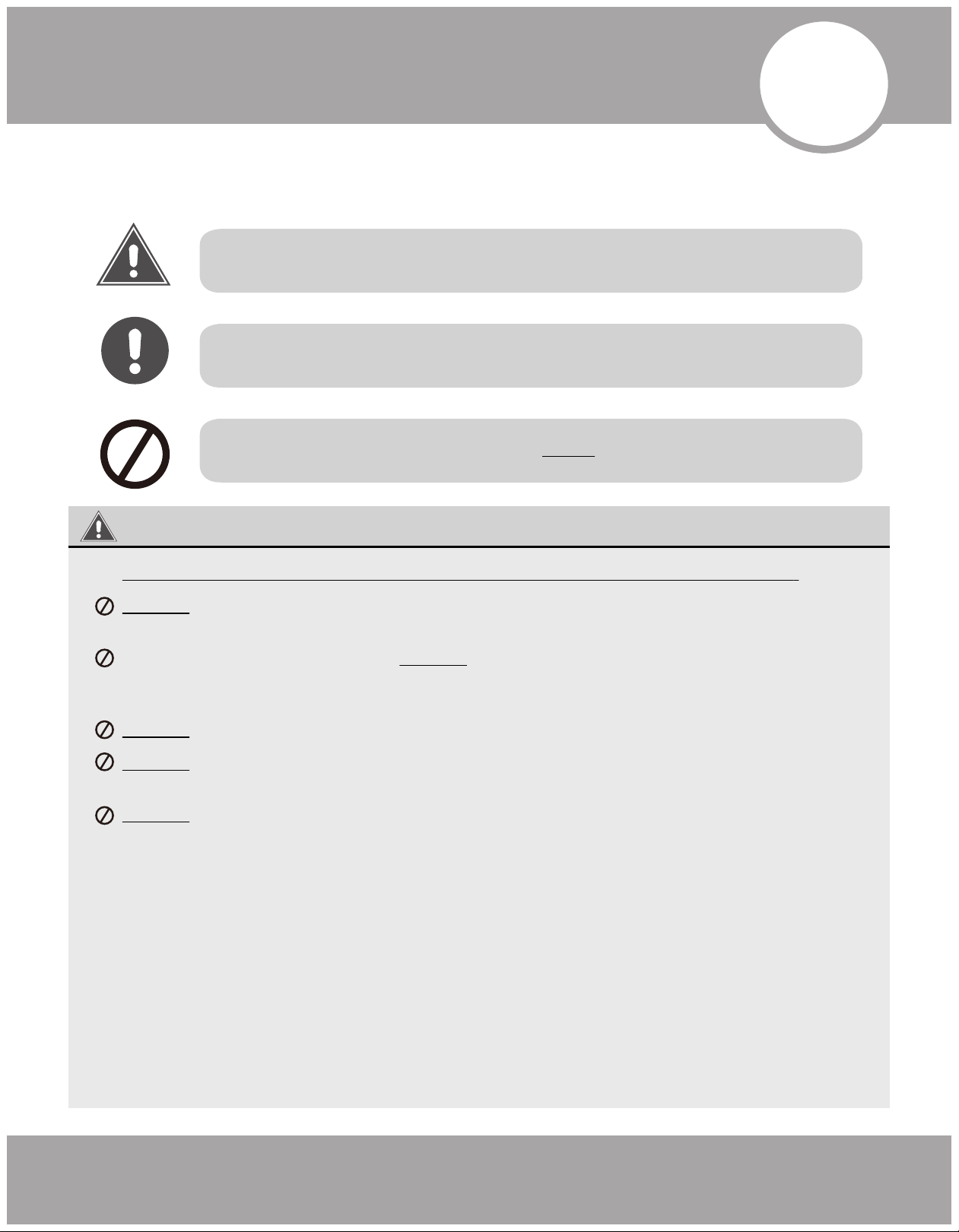
Incorrect installation may cause serious damage or injury.
The seriousness of potential damage or injuries is classified as either a WARNING or CAUTION.
WARNING
CAUTION
This symbol indicates ignoring instructions may cause death or serious injury.
This symbol indicates that ignoring instructions may cause moderate injury
to your person, damage to your unit, or other property.
This symbol indicates that you should NEVER perform the indicated action.
1.
2.
3.
4.
!
Safety Precautions
Page 3
Safety Precautions
mrcool.com
Note about Flourinated Gases:
1.
2.
3.
4.
5.
6.
7.
8.
9.
10.
11.
12.
13.
14.
6.
5.
Install the unit in a firm location that can support the unit’s weight. If the installation location
cannot support the weight, or the installation is performed improperly, the unit may fall and
cause serious injury and/or damage.
For all electrical work, follow all appropriate wiring standards, regulations, and the Installation
Manual.
You must use an independent circuit to supply power. Do not connect other appliances to the
same circuit. Insufficient electrical capacity or defects in electrical work can cause electrical
shock or fire.
For all electrical work, fuse the specified cables. Connect cables tightly and clamp them securely
to prevent external forces from damaging the terminal. Improper electrical connections may
overheat, causing fire and/or electrical shock.
All wiring must be properly arranged to ensure that the control board cover can close properly.
If the control board cover is not closed properly, it can lead to corrosion and cause the
connection points on the terminal to overheat , causing fire and/or electrical shock.
In certain functional environments, such as kitchens, server rooms, etc., the use of specially
designed air-conditioning units is highly recommended. If the supply cord is damaged, it must
be replaced by the manufacturer, its service agent, or similarly qualified persons in order to
avoid a hazard.
This appliance can be used by children aged 8 years and older and persons with reduced
physical, sensory, or mental capabilities or lack of experience and knowledge if they have been
given supervision or instruction concerning use of the appliance in a safe way and understand
the hazards involved. Children should not play with the appliance. Cleaning and user
maintenance should not be made by children without supervision.
The air conditioner unit can only be cleaned after it has been turned off and disconnected from
power, otherwise electric shock may occur.
If installed in a compact space, ensure that there is adequate ventilation in case of leakage.
Concentration of refrigerant gas can lead to explosion and other hazards.
The fixed wires connecting to this appliance must be configured with an all-pole disconnect
under voltage class III.
This air-conditioning unit contains R410A flourinated gases.
The refigerant gas may not have an odor, thus this should not be considered a means of leak
detection.
Installation, service, maintenance, and repair of this unit must be performed by a certified techni-
cian.
Product uninstallation and recycling must be performed by a certified technician.
If the system has a leak-detection system installed, it should be checked for leaks at least every 12
months.
Keep a record of all leak checks for the lifetime of the unit.
Page 4
Safety Precautions
mrcool.com
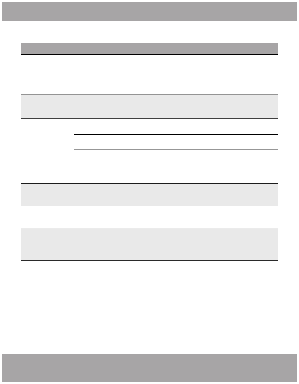
1.
2.
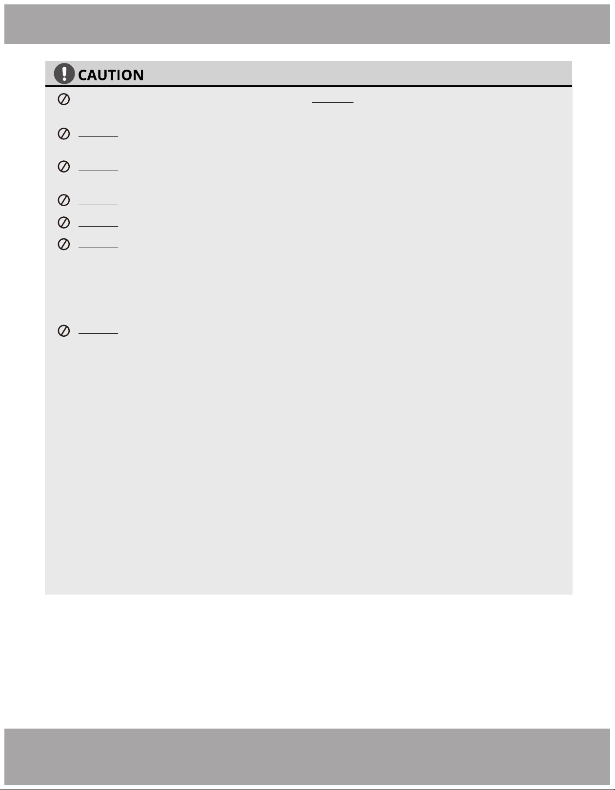
For units that have an auxiliary electric heater, DO NOT install the unit within 3 feet (1 meter) of
combustible materials.
DO NOT install the unit in a location that may be exposed to combustible gases. If combustible
gas accumulates around the unit, it may cause fire.
DO NOT operate your air conditioner in a wet room such as a bathroom or laundry room. Too
much exposure to water may cause electrical components to short circuit.
DO NOT put appendages or other objects into the air inlet or return grills.
DO NOT stop the appliance by directly cutting off the power. Turn off the unit first.
DO NOT install the appliance in areas with:
• oil, smoke, or volatile liquid; as plastic parts may deteriorate, adversely affecting the integrity
and functionality of the appliance.
• corrosive gas; as this may corrode copper piping and welds, adversely affecting the integrity
and functionality of the appliance.
DO NOT force-dry the filter using open flame or blowers, as this could damage it.
This appliance must be properly grounded during installation, or electrical shock may occur.
Install drainage piping according to the instructions in this manual. Improper drainage may
cause water damage to your home and property.
This appliance must be stored in a well ventilated area equal in size to the area specified for
operation.
Use proper measures to protect the unit from rodents and other small animals that may
damage electrical components, causing the unit to malfunction.
If wired control (i.e. a wall-mount thermostat) is to be used, it should be connected first before
powering up the unit, otherwise it may not funciton properly.
Only use a soft dry cloth or, as necessary, a slightly wet cloth with neutral detergent to clean
the casing of this appliance.
Before operating the unit under low temperature, connect it to power for 8 hours. If it is
deactivated for a short time, for example, one night, do not cut off the power (this is to protect
the compressor).
1.
2.
3.
4.
5.
6.
7.

Page 5
Safety Precautions
mrcool.com
To Our Customers;
Thank you for choosing a MRCOOL home HVAC product. Please read this manual carefully before installation
and operation of the Universal™ Series Air Handler to ensure correct use and handling. In addition to the
safety precautions in the previous section, please adhere to the following guidelines and note our exceptions
to liability.
1. This appliance can be used by children aged 8 years and older and persons with reduced physical, sensory
or mental capabilities or lack of experience and knowledge if they have been given supervision or instruction
concerning use of the appliance in a safe way and understand the hazards involved. Children should not play
with the appliance. Cleaning and user maintenance should not be made by children without supervision.
2. To ensure product reliability, the unit may consume power under stand-by status to maintain normal
communication, and for preheating refrigerant and lubricant. If the unit will not be used for an extended
period, disconnect the power supply. Reconnect the power supply and preheat the unit prior to use.
3. Ensure you have selected the proper model for the operating environment. Improper selection may impact
operating performance.
4. This product has undergone strict inspection and operational testing before leaving the factory. To avoid
damage due to improper disassembly, which may impact the normal operation, please do not disassemble the
unit without proper training and equipment.
5. For technical assistance, please contact MRCOOL technical support at (270) 366-0457.
6. If the product is malfunctioning and/or is inoperable, please contact MRCOOL technical support at the
aforementioned number, as soon as possible and provide the following information:
a. Product Nameplate Contents (model number, cooling / heating capacity, product serial number, factory
date)
b. Nature of Malfunction (specify the circumstances before and after the error occurred)
7. All illustrations and information in the instruction manual are for reference only. In order to improve the
product , we will continuously assess and innovate. We retain the right to make necessary revisions to the
product from time to time. We reserve the right to revise the contents of this manual without notice.
8. If the supply cord is damaged, it must be replaced by MRCOOL, a professional service agent or similarly
qualified person in order to avoid damage to the product.
9. MRCOOL, LLC assumes no responsibility for personal injury, property loss or equipment damage caused by
improper installation and commissioning, unecessary maintenance, or failure to follow relevant federal and
state regulations, industrial standards, and the requirements of this instuction manual.
10. MRCOOL, LLC will bear no responsibilities for personal injury or property damage caused by the following:
a. Improper use of the appliance
b. Altering, maintaining, or operating the product with non-approved equipment.
c. Altering, maintaining, or operating the product outside of the guidelines of this manual.
d. Defects caused by corrosive gas.
e. Defects caused by shipping damage.
f. Failure to abide by this instruction manual or government regulations.
g. Products made by other manufacturers
h. Natural disasters, improper installation environment, or force majeure.
1
Appliance Overview
Page 6mrcool.com
Appliance Overview
1
1
(this)
1
1
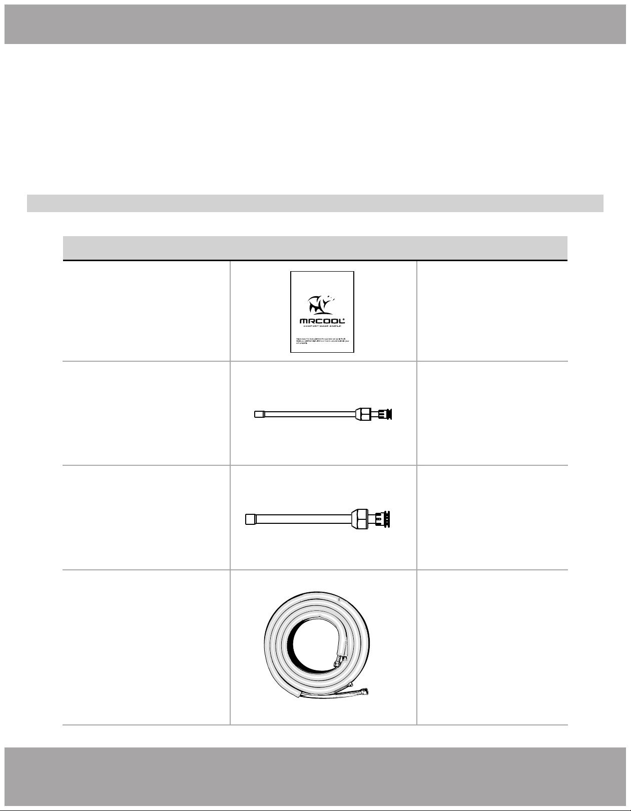
Owner’s Manual
Liquid Side Stub Kit
Gas Side Stub Kit
PART LOOKS LIKE... QUANTITY
Unless otherwise stated (as “OPTIONAL”) the air conditioning system includes the following accessories. Use
all of the installation parts and accessories to install the air conditioner. Improper installation may result in
water leakage, electrical shock, fire, or equipment failure.
Please read this manual carefully before installation and keep it for future reference.
Owner’s Manual
UNIVERSAL
™
Series
For more details visit www.MrCool.com
To connect the unit
with the liquid pipe
To connect the unit
with the gas pipe
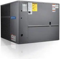
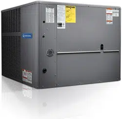
The Universal Series™ Air Handler offers the perfect combination of superior product quality, operating
efficiency, operating sound levels, and value for money. The condensing unit uses the environmentally friendly
refrigerant R410A, which is chlorine-free to help prevent damage to the ozone layer.
Accessories
OPTIONAL
No-Vac
®
Quick Connect
®
Lineset
Gas / Liquid
Pipe Assembly
Page 7 mrcool.com
Appliance Overview
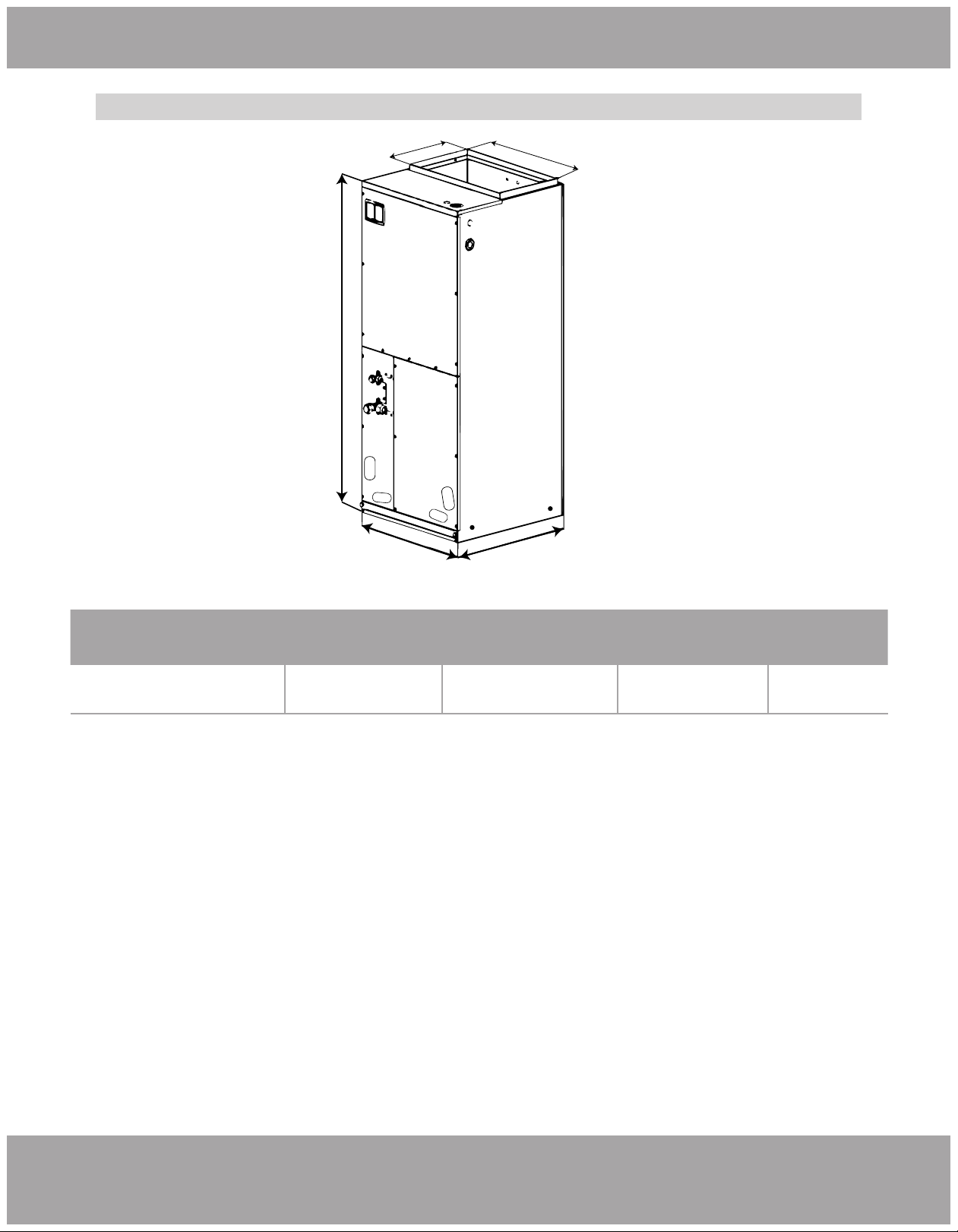
Fig. 1.1
Unit Dimensions
MDUI18024/MDUI18036
Unit Dimensions (Inches/MM)
Width Depth Height A B
21-1/4 in. (540mm)
21-1/4in. (540)mm 48-1/4in. (1224mm) 11-5/8in. (295mm) 20in. (508mm)
A
H
W
D
B
Page 8mrcool.com
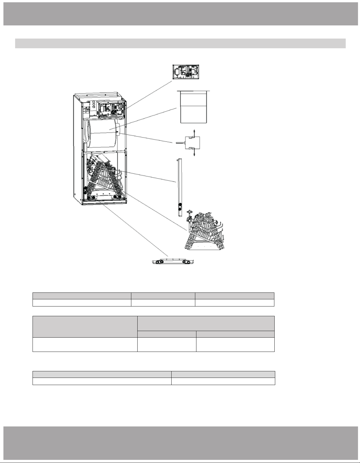
Appliance Overview
Main Parts
Electric Box
Assembly
Centrifugal Fan
Fan Motor
Secondary Drain Pan
Evaporator
Assembly
Primary Drain Pan
Model
Cooling capacity (ton)
Optional electric heater (kW)
MDUI18024 / MDUI18036
3.0
5-20
Model
Motor @ 230V ~, 60Hz
HP
FLA
MDUI18024 / MDUI18036 1/2 2.1
Unit: inch ( mm)
Model
Filter size
MDUI18024 / MDUI18036
19-5/16×20-5/16× 5/8(490×516×15)
Fig. 1.2
Page 9 mrcool.com
Pre-Installation Instructions
1. Checking Product Received
After receiving the product, please check for any damage caused by transportation. Shipping damage is the
responsibility of the carrier. Verify the model number, specifications, and accessories are correct prior to
installation. The distributor or manufacturer will not accept claims from dealers for transportation damage or
installation of incorrectly shipped units. If an incorrect unit is supplied, it must not be installed and it is to be
returned to the supplier. The manufacturer assumes no responsibility for the installation of incorrectly delivered
units.
2. Before Installation
Carefully read all instructions for the installation prior to installing product. Make sure each step or procedure is
understood and any special considerations are taken into account before starting installation. Assemble all tools,
hardware and supplies needed to complete the installation. Some items may need to be purchased separately.
Make sure everything needed to install the product is on hand before starting.
3. Codes & Regulations
This product is designed and manufactured to comply with national codes. It is installer’s responsibilities to install
the product in accordance with such codes and/or any prevailing local codes/regulations. The manufacturer
assumes no responsibilities for equipment installed in violation of any codes or regulations.
4. Replacement Parts... (continued on following page)
2
Unit Installation
CAUTION
• Before serving or installing this equipment, the electrical power to this unit must be in the “off” position.
• More than one electrical disconnect may exist on this unit. Failure to observe this warning may result in
electrical shock that can cause personal injury or death.
• Due to high system pressure and electrical shock potential, installation and service work can be
dangerous. Only trained and qualified persons are permitted to install or service this equipment.
Observe all warnings contained in this manual and labels/tags attached to the equipment.
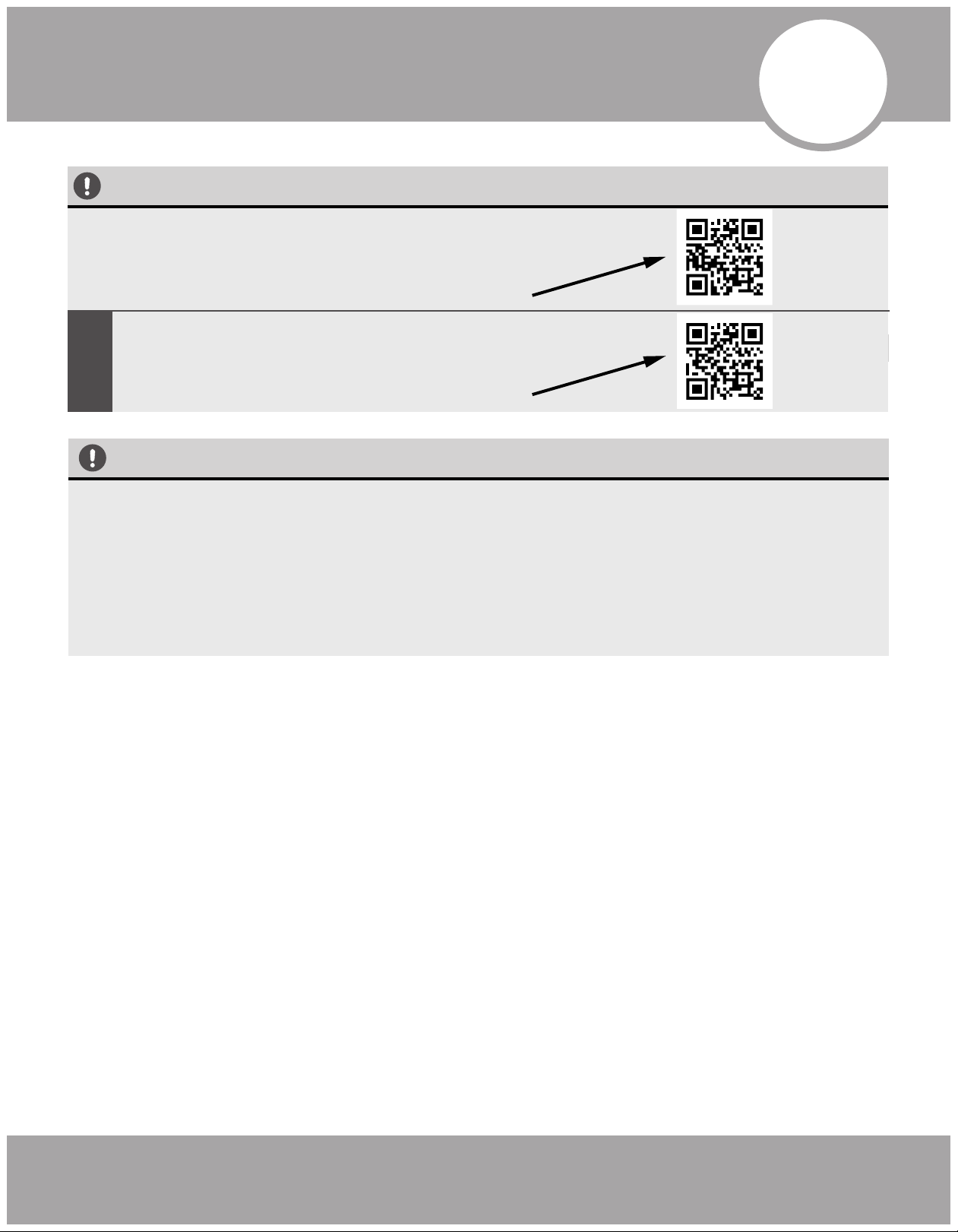
1. The Conventional Weld Line Set Installation
Instructions can be found on page 11
OR
View complete install video by scanning this QR code
2.
No-Vac
®
Quick Connect
®
Line Set
Installation
Instructions can be found on page 12
OR
View complete install video by scanning this QR code
The Universal™ Series has 2 installation methods
MRCOOL
®
Preferred Method
Page 10mrcool.com
Unit Installation
Installation Location
WARNING
• This air handler is designed for indoor installation only. Do not install it outdoors.
• When installing the air handler, take consideration to minimize the length of refrigerant tubing as
much as possible.
• When installing in an area directly over a finished ceiling (such as an attic), installation of an
emergency drain pan is required directly under the unit. See local and state codes for
requirements.
• When installing this unit in an area that may become wet, elevate the unit with a sturdy,
non-porous material. In installations that may lead to physical damage (i.e. a garage), it is advised
to install a protective barrier to prevent such damage.
This air handler is designed for a complete supply and return ductwork system. DO NOT operate
this product without complete ductwork attached.
DO NOT install the air handler in a location above or below the condenser that violates the
instructions provided with the condenser. Service clearance is to take precedence. Allow a
minimum of 24” service clearance in front of the unit.
DO NOT install the air handler in enclosed areas, such as garages, utility rooms or parking areas.
Carbon monoxide producing devices (such as an automobile, space heater, gas water heater, etc.)
should not be operated in enclosed areas such as unventilated garages, utility rooms or parking
areas because of the danger of carbon monoxide (CO) poisoning resulting from exhaust
emissions. If a furnace or air handler is installed in an enclosed area such as a garage, utility
room, or parking area, and a carbon monoxide producing device is operated therein, there must
be direct ventilation to the outside. Adequate ventilation is necessary to avoid the danger of CO
poisoning which can occur if a carbon monoxide producing device continues to operate in an
enclosed area. If these warnings are not followed, Carbon monoxide emission can be
(re)circulated throughout the building from the air handler causing serious illness including
permanent brain damage or death.
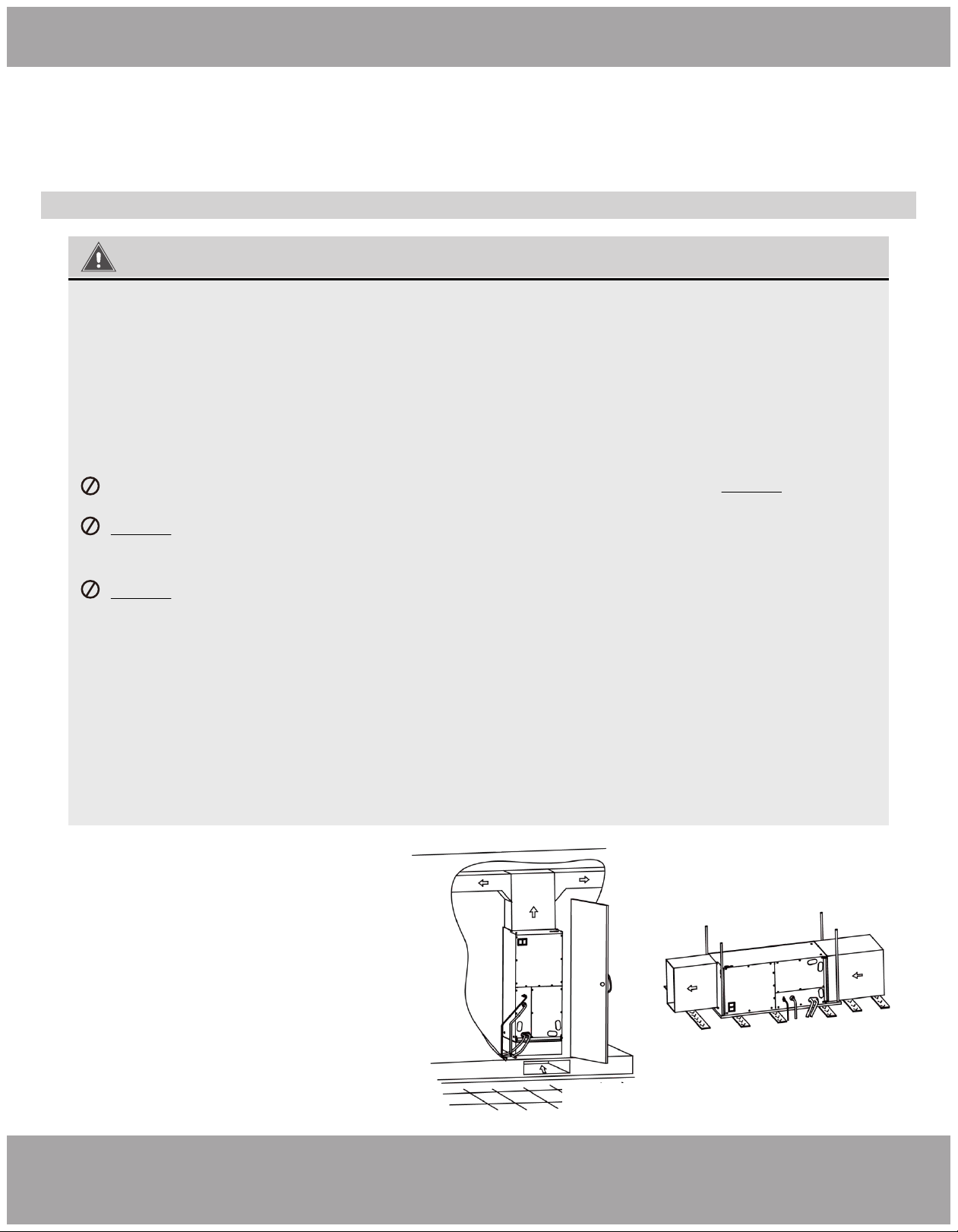
Fig. 2.1
Fig. 2.2
• If air handler is installed as Fig. 2.1, the air
handler should be concealed in a specific
room or space and make sure the air
handler is not accessible to the general
public.
• If air handler is installed as Fig. 2.2, make
sure there is enough space for care and
maintenance and the height between the air
handler and ground is above 8
feet/2500mm. and the air handler is not
accessible to the general public.
4. Replacement Parts
When reporting shortages or damages, or ordering repair parts, give the complete product model and serial
numbers as stamped on the product. Replacement parts for this product are available through your contractor or
local distributor.
Page 11 mrcool.com
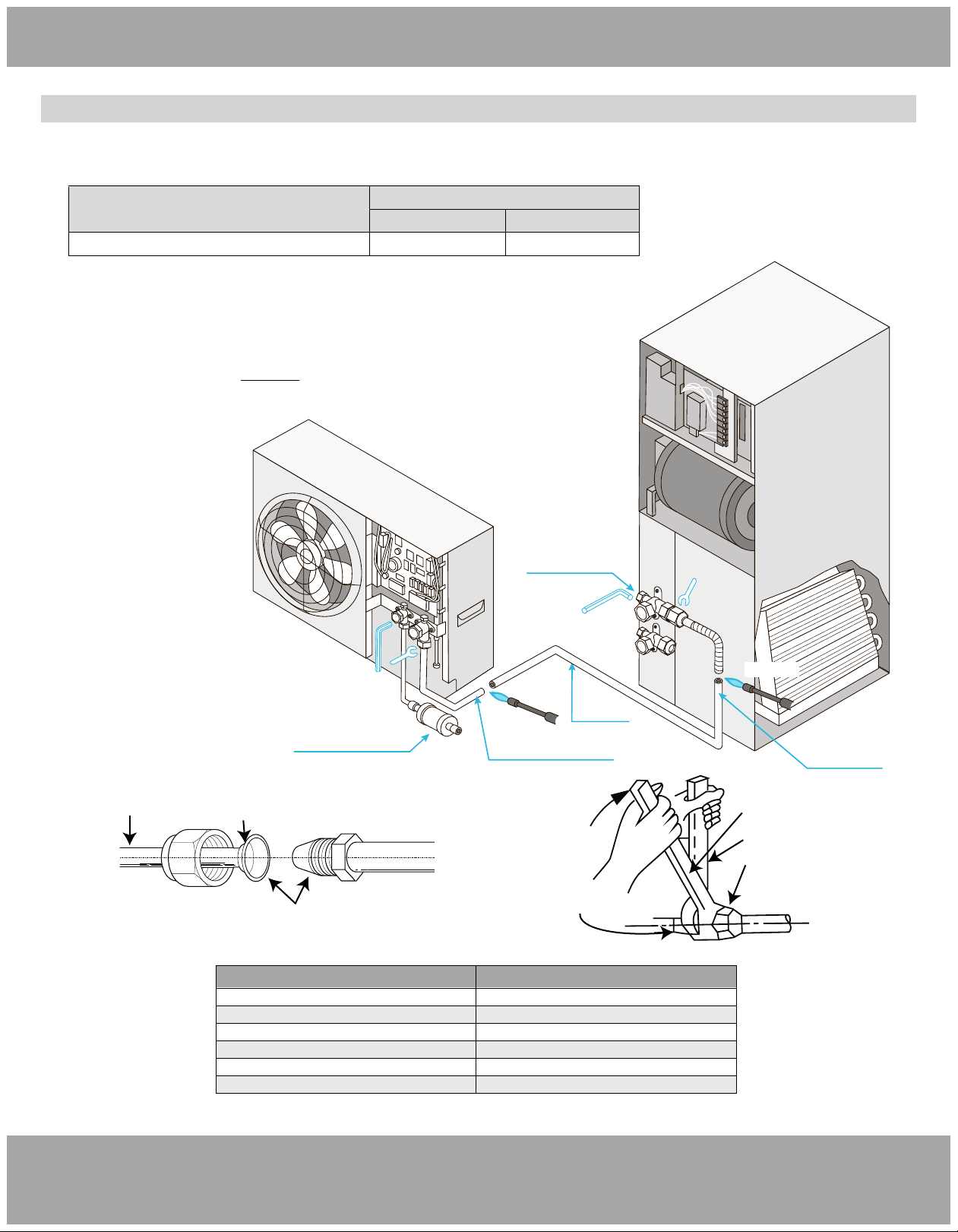
Unit Installation - OPTION 1: Conventional Weld / Flare Line Set
Conventional Line Set Installation
Specification of Connection Pipe
Piping Preparation
1.
WELD Type Complete Unit Replacement
All cut ends are to be round, burr free, and cleaned. Failure to follow this
practice increases the chances for refrigerant leakage. Line set size matches
service valve connection. DO NOT crimp service valve connector when pipe is
smaller than connector. See diagram below.
2. Screw Connection
Copper Piping
Oil Applied (to reduce
friction with the flare nut)
Oil Applied (improves
air-tight seal)
Fig. 2.5
Fig. 2.4
Fig. 2.3
Torque Wrench
Spanner
Piping Union
Flare Nut
Model
External diameter (inch)
Vapor pipe Liquid pipe
3/4 3/8
Pipe diameter (inch)
Tightening torque (N·m)
1/4
15-30
3/8
35-40
1/2
45-50
5/8
60-65
3/4
70-75
7/8
80-85
MDUI18024 / MDUI18036
Purge with
Nitrogen
Must open stop valves
after pulling vacuum
and before powering
on unit
Weld joint
Weld joint
Air Handler
MRCOOL Universal Series
DC Inverter
Open stop valves with allen
wrench only after nishing
lineset connections and before
powering on the unit
Must install lter
drier bi ow with this
installation type
Must Purge with Nitrogen
before brazing joints
Must Purge with
Nitrogen before
brazing joints
Page 12mrcool.com
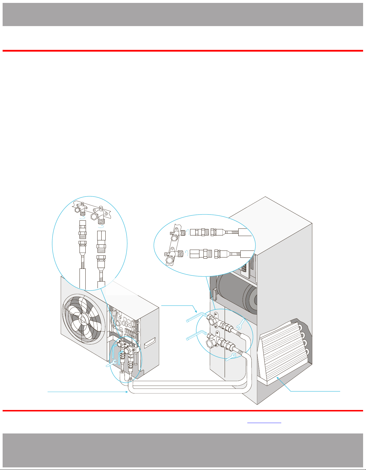
Unit Installation - OPTION 2: No-Vac
®
Quick Connect
®
Line Set
INSTRUCTIONS FOR USE WITH
NO-VAC™ QUICK CONNECT® LINE SET
SOLD SEPARATELY
KINK RESISTANT, PRECHARGED, SIMPLE SECURE QUICK CONNECT, 100% CONNECTION GUARANTEE
www.mrcool.com
v01-07-2020
:
1.
Take out matching male connectors M1 and M2.
2.
DC INVERTER and ensure the threads are clean and complete.
3.
the M1 connector to the
the M2 connector to the
4.
Repeat AIR HANDLER LINE SET.
Unroll and route the LINE SET between the AIR HANDLER and the DC INVERTER.
6.
LINE SET.
7.
the LINE SET F1 valve to the M1 Connector 45N. the LINE SET F2 valve to the
M2 Connector 45N.
8. Repeat AIR HANDLER LINE SET.
9.
At the the at the and open the with a hex wrench to
If close the valve and that steps
3 and 7 Otherwise
close the valve and that steps 3 and 7
10. the
valve’s and
to help .
ⱡFailure to follow the instrucons provided could result in severe harm to you, this product, or other property.
The manufacturer, distributor, and seller are not responsible for any harm resulng from the failure to follow
instrucons and the failure to follow these instrucons will void any and all warranes express or implied.
50 N
50 N
70 N
70 N
M1
F1
M1
F1
M2
F2
M2 F2
*1
*1
*2
*2
3/8”
3/8”
3/4”
3/4”
Complete Unit Replacement
Using The No Vac® Quick Connect® Lines
Air Handler
Open the stop valve
only after connecting
the refrigerate lines
A-coil Precharged
with 410 Refrigerate
Connect using precharged
line set with quick connect
ttings in length 15, 25, 35, 50 feet
MRCOOL Universal Series
DC Inverter
Page 13 mrcool.com
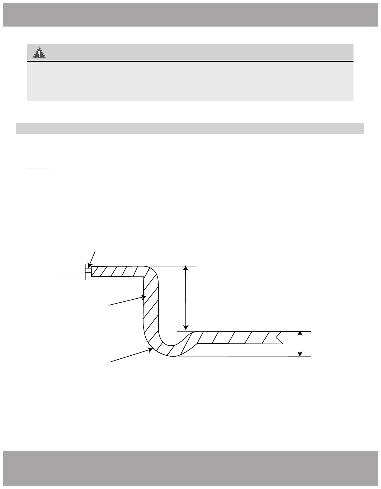
Unit Installation
Condensate Removal
1. DO NOT connect the condensate drain pipe into the waste pipe or other pipelines that are likely to produce corrosive or
peculiar smells. This will prevent odors from entering indoors or corrupting the unit.
2. DO NOT connect the condensate drain pipe into the rain pipe. This will prevent rain water from pouring in and causing
property loss or personal injury.
3. The condensate drain pipe should be connected into a special drain system for the unit.
4. The drain pan has primary and secondary drain connections. Condensate removal is performed by attaching a 3/4” PVC
pipe to the evaporator coil pan and terminated in accordance with local or state Plumbing/HVAC codes. The installation
must include a “P” style trap that is located closely to the evaporator coil. DO NOT over-tighten the drain connection in
order to prevent damage to the evaporator drain pan. See the following figure for details of a typical condensate line “P”
trap.
Drain Connection
2” Minimum
3” Minimum
Flexible Tubing
(Hose or Pipe)
Positive Liquid Seal
(Required)
Unit
IMPORTANT
The cutoff valves on the air handlers must be opened AFTER connecting the lines
and BEFORE turning on the unit. Otherwise, operation can cause leakage and/or
damage to the unit.
Fig. 2.6
Page 14mrcool.com
Unit Installation
Ductwork
This air handler is designed for a complete supply and return ductwork system.
Return ductwork:
Do not dispose of the return ductwork in an area that can introduce toxic, or objectionable
fumes/odors into the ductwork. The return ductwork is to be introduced into the air handler
bottom (upflow configuration).
Return Air Filters:
Each installation must include a return air filter for the air handler or externally using a return air
filter grille.
WARNING
DO NOT operate the unit without all ductwork completed and attached.
• Inadequate ductwork that restricts airflow can result in improper performance and compressor
or heater failure.
• Ductwork is to be constructed in a manner that limits restrictions and maintains suitable air
velocity.
• Ductwork is to be sealed to the unit in a manner that will prevent leakage.
Electric Heater
The air handlers listed in this manual do not have a factory installed electric heater. An electric heat kit is
available as an accessory. The only heater kits that can be used are HNRd series. Please refer to installation
instructions provided with heater kit for the correct installation procedure.
WARNING
• The electrical characteristics of the air handler, the electric heater kit, and the supply power
should be identical.
Page 15 mrcool.com
Unit Installation
CAUTION
1. Ensure that all power supply is disconnected prior to installing the heater kit.
2. A means of strain relief and conductor protection must be provided at the supply wire entrance into
cabinet.
3. Only use copper conductors.
4. Installation must follow national electric code and other applicable codes.
5. If this appliance is installed in an enclosed area such as a garage or utility room with any carbon
monoxide producing appliance, ensure the area is properly ventilated to the outside.
1) Refer to the Table below for the appropriate HNRd
heater kit.
2) Check for any physical damage; do not install
damaged heater kit.
3) Remove the upper access panel from air handler.
4) Remove cover plate from air handler.
5) Slide the heater kit in to the slot and secure
element plate with previously removed screws.
6) Insert power leads into the circuit breaker lugs or
stripped red and black wires (for heater kit without
circuit breaker) and tighten.
7) Connect ground wire to ground lug.
8) Break out appropriate area of the plastic circuit
breaker cover on the access panel of the air
handler.
9) Replace access panel and check operation.
Cover Plate
Heater Kit
Circuit Breaker
Bolt
Fig 2.7
HNRd5-D
HNRd8-D
Circuit breaker, 5kW heat strip
Circuit breaker, 8kW heat strip
HNRd10-D Circuit breaker, 10kW heat strip
Kit #. Description
HNRd15-D Circuit breaker, 15kW heat strip
HNRd20-D Circuit breaker, 20kW heat strip
Kit #. Description
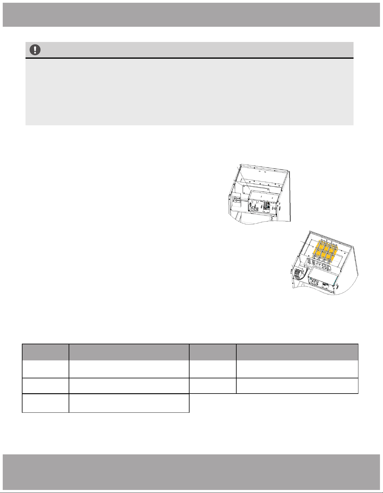
NOTE
Refer to the Universal Condenser Manual for the Dip Switch instructions and settings for the condenser.
mrcool.com Page 16
Fig. 2.8 Fig. 2.9
Location of
Dip Switch on
Air Handler
Main Board
Unit Installation
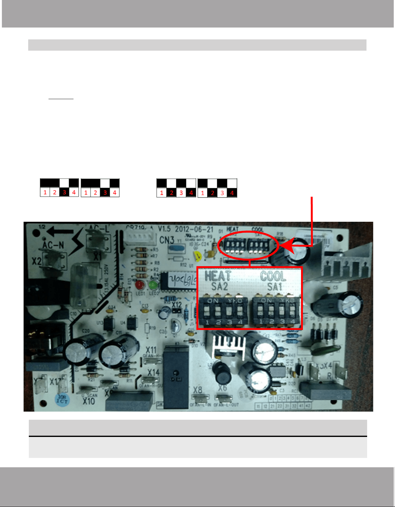
Converting Unit From 3 Ton to 2 Ton
Follow these instructions during unit installation in order to enable a Universal Series 3 ton condenser
and air handler split system to operate at 2 ton capacity.
1. DO NOT attempt this conversion while the unit is powered on.
2. Locate the capacity dip switch on the air handler main board. The capacity dip switch is circled on
the photo below.
3. The default position of the capacity dip switch is 1, 2, & 4 ‘Up’ and 3 ‘Down’ on both the SA2 and
SA1 switches.
4. The default position of the capacity dip switch is 36k.
5. To activate the 24k capacity, flip capacity dip switch 2 & 4 on SA2 and SA1 to Down. Flip capacity
dip switch 3 on SA2 and SA1 to Up.
Air Handler Field Conversion
DEFAULT 3 TON 2 TON SETTING
Page 17
mrcool.com
Unit Installation
WARNING Before performing electrical work, read the following regulations
1. Electrical installation must be conducted by professionals in compliance with local laws,
regulations and this installation manual. Never artificially extend the length of a power cord. The
electric circuit must be equipped with a circuit breaker and air switch. Both must have sufficient
capacity.
2. Unit operating power must be within the nominal range stated in the instruction manual. Use
a specialized power circuit for the unit. Do not draw power from another power circuit.
3. The air conditioner circuit should be at least 1.5m away from any flammable surface.
4. The external power cord and signal wire must be effectively fixed.
5. The external power cord and signal wire must NOT directly contact any hot objects. For
example: they must not come into contact with chimney pipes, warm gas pipes or other hot
objects.
6. The external power cord and signal wire must NOT be squeezed. Never pull, stretch or bend
the wires.
7. The external power cord and signal wire must NOT collide with any metal beam or edge on
the ceiling, or touch any metal burrs or sharp metal edge.
8. Connect wires in accordance to the circuit diagram labeled on the unit or electric box. Screws
must be tightened. Slipped screws must be replaced by specialized flat-head screws.
9. Please use the power cables that are packaged with the appliance. DO NOT change the power
cables arbitrarily. Do not change the length and terminals of the power cables. If you want to
change the power cables, please contact MRCOOL’s local service center.
10. Wiring terminals should be connected firmly to the terminal board. Loose connection is not
safe.
11. After the electrical installation is finished, please use wire clamps to secure the power cord,
connection wire of temperature controller and outdoor unit, and the communication cords. Make
sure the wires are not clamped too tight.
12. The wire gauge of the power cord should be sufficiently large. A damaged power cord or
other wires must be replaced by specialized wires. Wiring work must be done according to
national wiring rules and regulations.
Vacuum Lines
Electrical Connection
Electrical Regulations
Page 18mrcool.com
Unit Installation
Outdoor Unit Model Power Supply
Max. Overcurrent
Protection (A)
208/230V
60Hz
15 amps5 amps
MDUI18024/MDUI18036
Min. Circuit
Ampacity
Electrical Connection
Electrical Parameters
1. The fuse is located on the main board.
2. Install a circuit breaker at every power terminal near the units (indoor unit and temperature controller)
with at least 0.12in (3mm) contact gap. Both units must reach the plug.
3. Circuit breaker and power cord specifications listed in the above table are determined based on the
maximum power input of the units.
4. Specifications of power cords listed in the above table are applicable in a working condition where
ambient temperature is 104°F (40°C) and multi-core copper cable (e.g. YJV copper cable, with insulated
PE and PVC sheath) is protected by a conduit, and is resistant to 194°F (90°C) in maximum (see IEC
60364-5-52). If working conditions change, please adjust the specifications according to national
standards.
5. Specifications of circuit breaker are based on a working condition where the working temperature is
104°F (40°C). If working conditions change, please adjust the specifications according to national
standards.
6. Use 5pc of AWG18 power cords as the signal wire between the indoor unit and the temperature
controller. The maximum length is 98 feet (30m). Please select a proper length according to local
conditions. Communication cords must not be twisted together.
7. The gauge of signal wire should not be less than AWG18. It’s recommended to use AWG18 power cords
as the signal wire.
Page 19 mrcool.com
Unit Installation
Electrical Connection
Connecting the Power Cord & Communication Wire
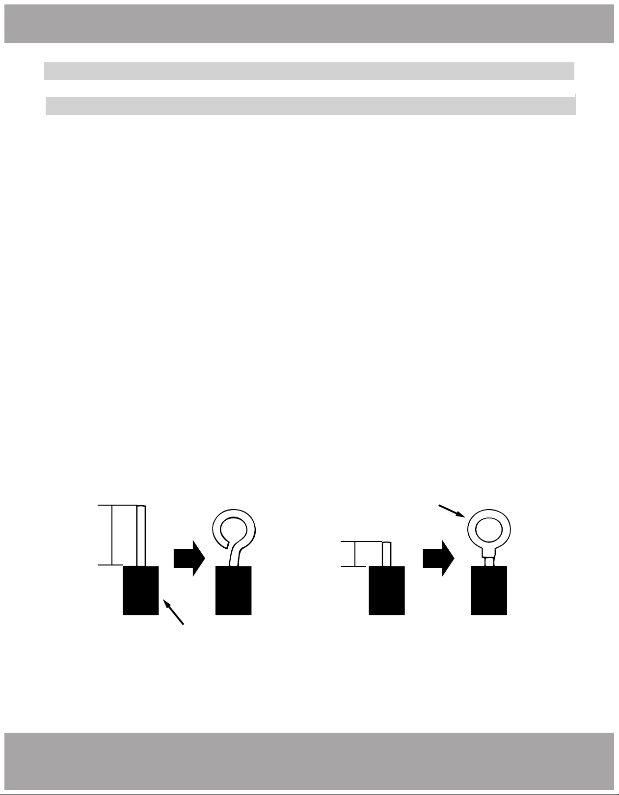
For solid wires (Refer to Fig. 2.10 A):
1. Use wire cutters to cut off the wire end and then peel away about 25mm of the insulation layer.
2. Use a screwdriver to unscrew the terminal screw on the terminal board.
3. Use nippers to bend the solid wire into a ring that fits the terminal screw.
4. Form a proper ring and attach to the terminal board. Use a screwdriver to tighten the terminal screw.
For braided wires (Refer to Fig. 2.10 B & Fig. 2.10):
1. Use wire cutters to cut off the wire end and then peel away about 10mm of the insulation layer.
2. Use a screwdriver to unscrew the terminal screw on the terminal board.
3. Use a round terminal fastener or clamp to secure the round terminal firmly on the peeled wire end.
4. Locate the round terminal conduit. Use a screwdriver to replace it and tighten the terminal screw (as
shown in Fig. 2.10).
A. Solid Wire
Jacket / Insulation
1” (25mm)
B. Braided Wire
Solderless
Terminal
3/8” (10mm)
Fig. 2.10
Page 20mrcool.com
Unit Installation
Electrical Connection
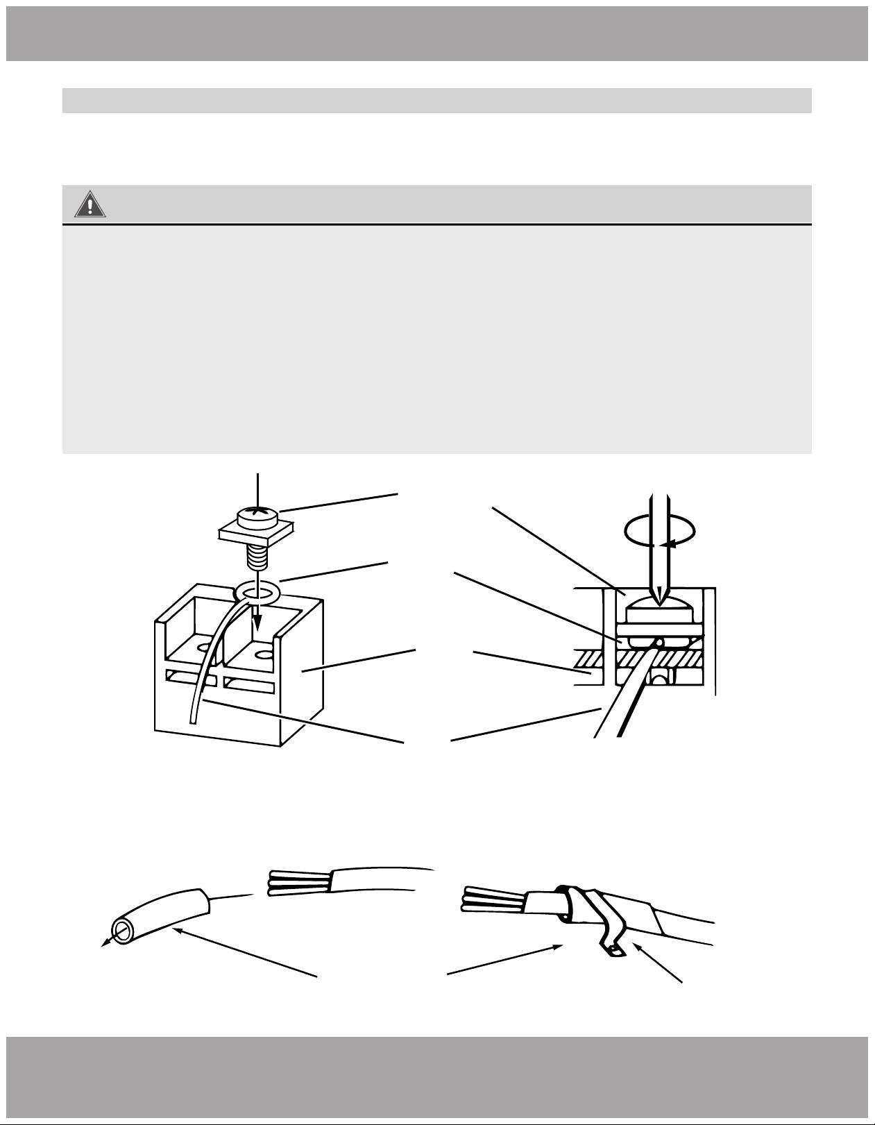
Connecting the Power Cord & Communication Wire
Screw with
Special Fastener
Round
Terminal
Wire
Terminal
Board
For all terminal wiring (Refer to Fig. 2.13 on the next page):
Lead the connection wire and power cord through the insulation tube. Then secure
the wires with wire clamps (as shown in Fig. 2.12).
Fig. 2.12
Fig. 2.11
Cord Clamp
Insulation Tube
WARNING
1. Before work begins, please check to ensure the unit is powered OFF.
2. Match the terminal numbers and wire colors with the colors indicated in the indoor unit.
3. Wrong wire connection may burn the electrical components.
4. Connect the wires firmly to the wiring box. Incomplete installation may lead to a fire hazard.
5. Please use wire clamps to secure the external covers of connecting wires. (Insulators must be
clamped securely; otherwise, electric leakage may occur.)
6. Ground wire should be connected.
Page 21 mrcool.com
Unit Installation
WARNING
1. High and low voltage wires should be led through different rubber rings of the electric box
cover.
2. Do not bundle the temperature controller wires or lay them side by side, otherwise errors will
occur.
3. High and low voltage wires should be secured separately. Secure the former ones with large
clamps and the latter ones with small clamps.
4. Use screws to tighten the power cord and signal wire of the units on the terminal board.
Improper connection may create a fire hazard.
5. If the power cord and communication wire are not correctly connected, the air conditioner
may suffer damage.
6. Ground the units by connecting the ground wire.
7. The units should comply with applicable local and national rules and regulations on power
consumption.
8. When connecting the power cord, make sure the phase sequence of the power supply
matches with the corresponding terminals, otherwise the compressor will get reversed and
operate abnormally.
Electrical Connection
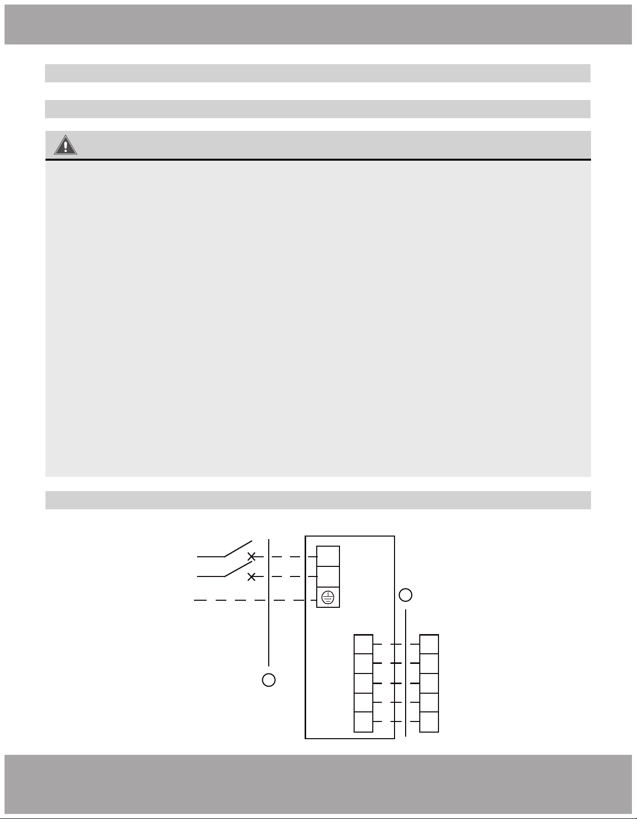
Connecting the Power Cord & Communication Wire
POWE R
Breaker
208-230V L1
1PH L2
60Hz G
L1
L2
B O/B
W1
R
C
G
W1
R
C
G
Temperature
Controller
Electrical wiring of Single-phase unit: MDUI18024/MDUI18036
Fig. 2.13
2
1
INDOOR
UNIT
Page 22mrcool.com
Refrigerant Piping Connection
List of Checks to Perform Possible Malfunctions PASS/FAIL
Is the main body installed securely?
Did you conduct a water leakage test?
Is the unit well insulated from heat?
Does water drain properly from drain
hose?
Is the voltage consistent with
specifications stated on the nameplate?
Are the wires, piping, and valves
installed correctly?
Has the unit been safely grounded?
Do the wire specifications wires comply
with the requirement?
Are there any obstacles blocking the
air inlet or outlet of the units?
Have you recorded the length of
refrigerant pipe and the refrigerant
charging amount?
Is the panel mounted firmly?
Are there any cracks in the air return
or supply pipe?
The unit may fall down, vibrate or produce
noise.
Cooling capacity may become
unsatisfactory.
Condensate, water drops may occur
Condensate, water drops may occur
The unit may fail or its components may
get burned.
The unit may fail or its components may
ignite.
Risk of electric leakage.
The unit may fail or its components may
ignite.
Cooling capacity may become
unsatisfactory.
The refrigerant charging amount can’t be
controlled.
It may cause air leak, vibration, and
condensation.
It may cause air leak, vibration, and
condensation.
Before Test Run
Only perform test run after you have completed the following steps:
• Electrical Safety Checks – Confirm that the electrical system is safe and operating properly
• Gas Leak Checks – Check all flare nut connections and confirm that the system is not leaking
• Confirm that gas and liquid (high and low pressure) valves are fully open
3
Post Installation Checks

Page 23 mrcool.com
Post Installation Checks
Preparation Before Connecting The Power:
1. Power must not be connected if the installation work is not completed.
2. Verify the control circuit is correct and all the wires are firmly connected. Valves on the vapor and liquid
line should be completely open.
3. Remove any scattered objects, especially metal filing, thrum, and clip.
4. Ensure the unit’s appearance and piping system has not been damaged during transportation or handling.
5. Check for any loose terminals and ensure the phases are correct.
Operation After Connecting The Power:
1. If all the above steps are complete, power on the unit.
2. If there are any loud and/or abnormal sounds, turn off the unit and contact MRCOOL Tech Support
immediately.
3. Verify the unit operates normally under several modes.
Test Run
Page 24mrcool.com
Outdoor Unit Installation
Maintenance
4
4
Troubleshooting
(1) If your air conditioner fails to function normally, check the following items before conducting
maintenance:
Problem Cause Corrective Measure
The unit
will not activate.
Abnormal cooling
or heating.
The unit operates
but stops
immediately.
The unit isn’t connected to a power
supply.
Low voltage.
Fuse broken or circuit breaker trips o.
Connect to power supply.
Check the circuit voltage is within
rated scope.
Replace fuse or reconnect breaker.
Remove obstacles.
Adjust setting at wired controller.
Close the door or windows.
Draw curtain or louver.
Reduce heat source.
Clean the lter.
Air inlet and outlet of the units have
been blocked.
Air inlet and outlet of the units have
been blocked.
Filter screen is blocked by dirt.
Too much heat source in the room.
Doors or windows are opened.
Direct sunshine.
Inappropriate temperature setting.
Clear any obstacles and keep the area
well ventilated.
NOTICE
Check the above items and take appropriate corrective measures. If the unit
continues to function improperly, immediatey disconnect power and contact MRCOOL or your
installation dealer.
Page 25 mrcool.com
Troubleshooting
Problem Time of Occurrence Cause
Mist comes from the
unit.
Unit doesn’t run.
The unit
generates noise.
The unit
emits odor.
Indoor unit still
runs after
switched o.
Dust comes from
the unit.
During operation.
When power is turned on.
When unit is started immediately after it
is just turned o.
There is a continuous sound when cooling.
The unit makes a sound when unit
starts or stops.
Slight cracking sound is heard when unit
is turned on.
Electronic expansion valve initialization
can cause this noise temporarily.
There is slight and continuous sound
when unit is running or after running.
When unit runs after no operation for
a long period of time.
After every indoor unit receives "stop"
signal, fan will keep running.
If the unit is running under high
humidity, the wet air in the room will be
quickly cooled down.
Overload protection switch causes a 3
minute delay.
Start up could be delayed up to
1 minute.
Gas refrigerant ow can cause a slight noise.
Gas refrigerant ow can cause a slight noise.
The drainage system can cause this
noise during operation.
Dust has settled inside the indoor unit.
During operation.
Smells from the operating environment
may be pulled through the air handler.
Indoor fan can be set as “ON” or “AUTO”
mode. Under “ON” mode, indoor fan
will keep running after switching o the
unit.
(2) The following situations are not operation failures.
Page 26mrcool.com
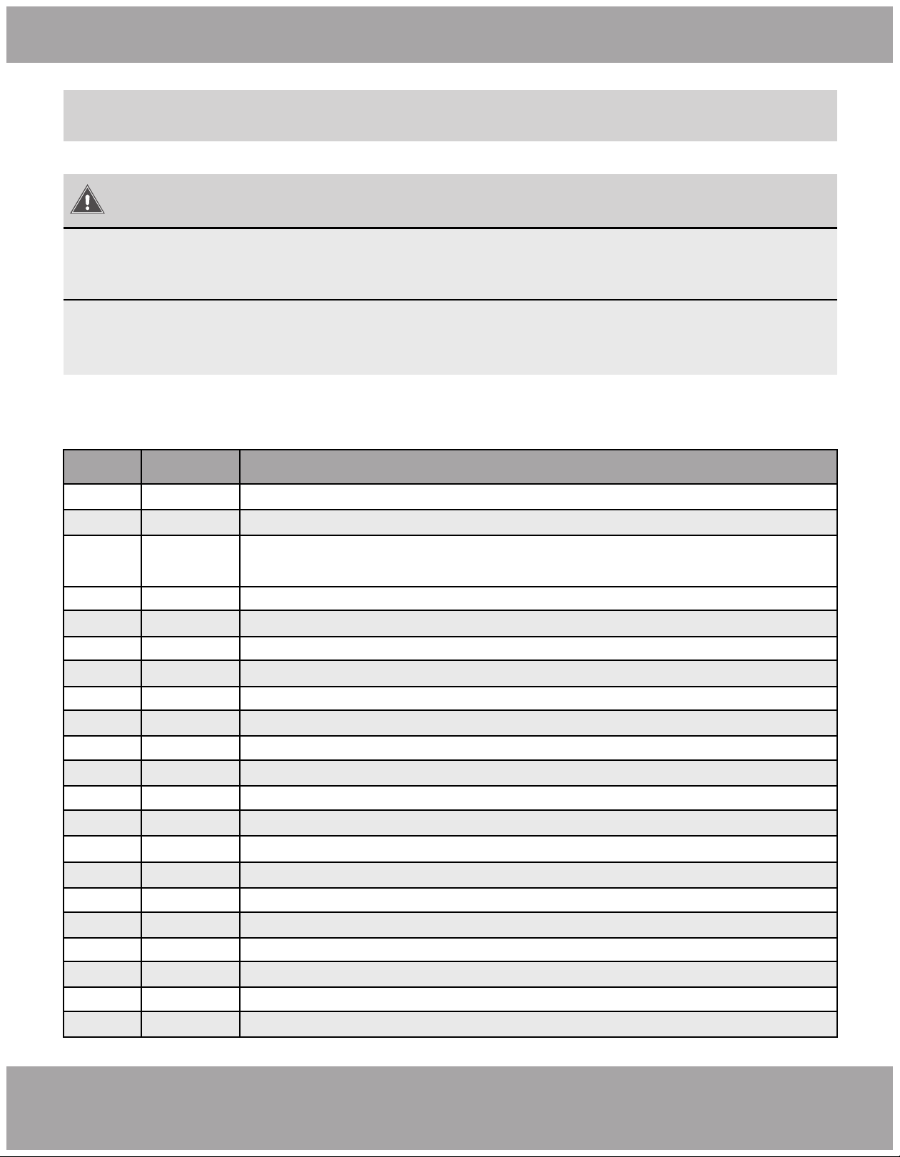
Troubleshooting
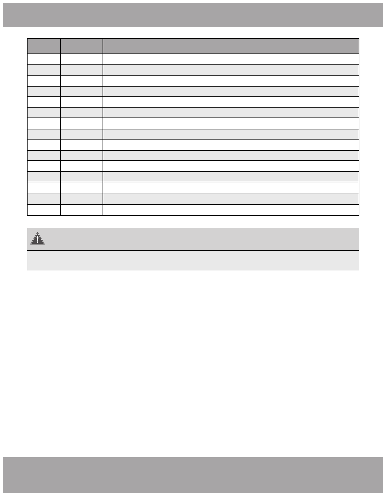
Error Code
WARNING
1) When abnormalities occur, stop the unit immediately and disconnect power. Contact
MRCOOL. If the unit continues to run abnormally, it may damage the unit and cause an
electric shock or a fire hazard.
2) DO NOT attempt repairs to the appliance yourself. Improper repair and maintenance
can create electric shock and fire hazards. Please contact MRCOOL Tech Support for
further guidance or a qualified professional for repairs.
Number Error Code Error
1 E1 Compressor high pressure protection
2 E4 Compressor air discharge high-temperature protection
4 F2 Condenser temperature sensor error
5 F3 Outdoor ambient temperature sensor error
6 F4 Discharge temperature sensor error
7 F6 Outdoor unit tube temperature sensor error
8 C5 Indoor unit jumper cap error
9 EE Outdoor unit memory chip error
10 PF Electric box sensor error
11 H3 Compressor overload protection
12 H4 Overload
13 H5 IPM protection
14 H6 DC fan error
15 H7 Driver out-of-step protection
16 HC Pfc protection
17 Lc Startup failure
18 Ld Compressor phase-sequence protection
19 LF Power protection
20 U7 4-way valve switch-over error
21 P0 Drive reset protection
3 E3
Compressor low pressure protection, refrigerant lack protection and refrigerant
collecting mode
If the display panel or wired control displays an error code, please refer to the following table:
Page 27 mrcool.com
Troubleshooting
Number Error Code Error
22 P5 Over-current protection
23 P6 Master control and driver communication error
Driver module sensor error
25 P8 Driver module high temperature protection
26 P9 Zero-crossing protection
27 PA AC current protection
28 Pc Driver current error
29 Pd Sensor connection protection
30 PE Temperature drift protection
31 PL Bus low-voltage protection
32 PH Bus high-voltage protection
33 PU Charge loop error
34 PP Input voltage error
35 ee Driver memory chip error
36 C4 ODU jumper cap error
24 P7
NOTICE
When the unit is connected with the wired controller, the error code will show simultaneously
on it.
5
Page 28mrcool.com
Maintenance and Care
Drain Pipe
Notice Before Seasonal Use
Regular check, maintenance, and care should be performed by professional personnel,
which will prolong the life span of the unit.
Regularly check the drain pipe for clogs in order to ensure smooth condensate drainage.
Purchase replacement parts from local appointed service center or dealer if necessary.
1. Check if the inlet/outlet of the indoor unit is clogged.
2. Check if the ground wire is earthed reliably.
3. Check if the filter screen has been set soundly.
4. Check if the unit is installed firmly. If there is something abnormal, please contact the local appointed
service center.
Maintenance After Seasonal Use
Parts Replacement
If the air-conditioning unit you purchased has any quality problem or you have any inquiry, please contact the
Mr. Cool Tech Support.
Warranty should meet the following requirements:
1. First run of the unit should be operated by professional personnel from factory appointed service center.
2. Only factory manufactured accessories can be used on the machine.
3. All the instructions listed in this manual should be followed.
4. Warranty will be automatically voiced if the above requirements are not met.
After-Sales Service
1.
Cut off main power supply of the unit.
2. Clean filter screen of indoor units.
3. Clean the dust from the indoor units.
4. In the event of rusting, use anti-rust paint to stop the spreading of rust.
Page 29 mrcool.com
Refrigerant Piping Connection
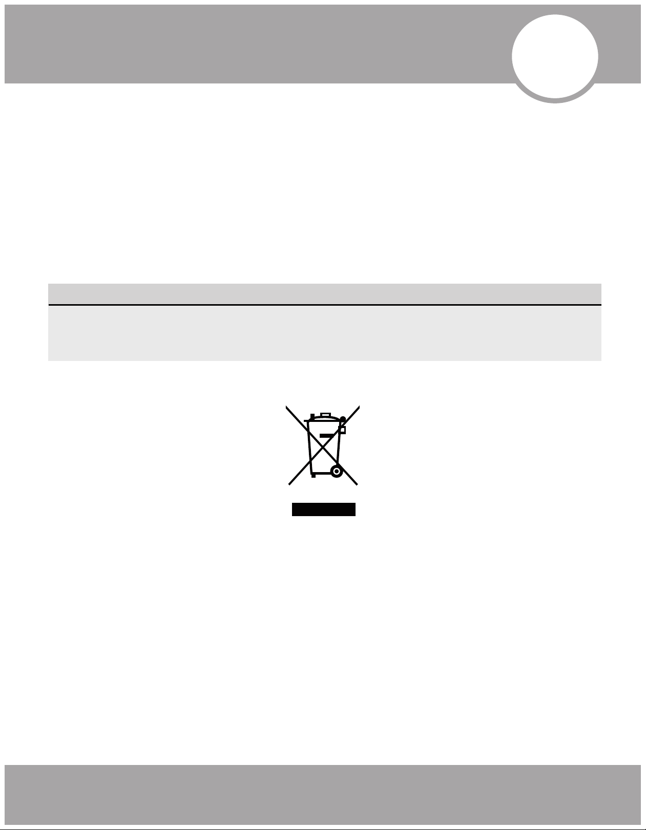
Special notice
This appliance contains refrigerant and other potentially hazardous materials. When disposing of this appli-
ance, the law requires special collection and treatment. DO NOT dispose of this product as household waste
or unsorted municipal waste.
When disposing of this appliance, you have the following options:
• Dispose of the appliance at a designated municipal electronic waste collection facility.
• When buying a new appliance, the retailer will receive the old appliance free of charge.
• The manufacturer will receive the old appliance free of charge.
• Sell the appliance to certified scrap metal dealers.
Disposing of this appliance in the forest or other natural surroundings endangers your health
and is bad for the environment. Hazardous substances may leak into the ground water and
enter the food chain.
6
EU Disposal Guidelines
Universal™ Series
The design and specifications of this product and/or manual are subject to change without prior notice.
Consult with the sales agency or manufacturer for details.
Copyright © 2019 MRCOOL, LLC.
ELECTRICIAN and/or HVAC TECHNICIAN:
LICENSE #:
INSTALLATION DATE:
INSTALLATION LOCATION:
SERIAL NUMBER: