Loading ...
Loading ...
Loading ...
Compact Unit / Utility Heater
16
Operating Instructions and Owner’s Manual
6
5
4
3
2
1
0
1
2
3
4
5
6
6
5
4
3
2
1
0
1
2
3
4
5
6
4”
10”
N.G. L.P.
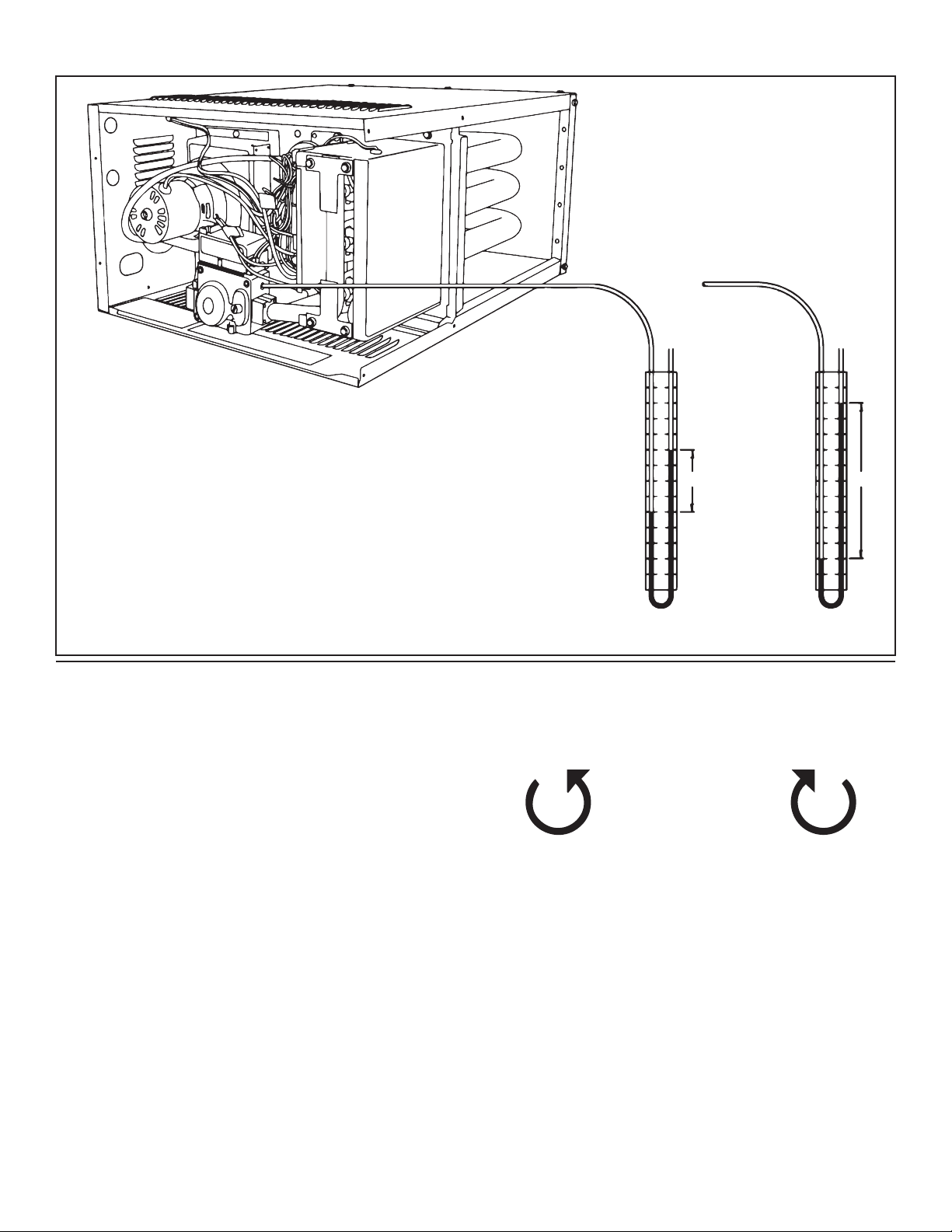
FIGURE 12
Step 5
Rotate the valve/ manifold assembly back up into the burner box,
making sure that all the orifices are indexed into the burners and are
not caught on the locating ring on the back of each burner. Secure
the manifold to the burner box with the four screws removed in step 2.
Step 6
Following the instructions in the unit heaters operations manual
mount the heater and connect the gas supply (making sure to leak
check all connections with soapy water).
Step 7
Remove valve pressure test plug and retain for later use. Connect a
water-filled U-tube manometer to the test port. See Figure 12. Use a
manometer because test gauges are not reliable and may give a false
reading.
Step 8
Connect main electrical power supply, and turn main gas supply on.
Step 9
Turn up the thermostat to call for heat, thereby starting the ignition
sequence for the heater.
Step 10
When the burners light, set the manifold gas pressure by turning the
adjustment screw to the regulator spring that was replaced in step 6.
Once the pressure has been adjusted, replace the adjustment screw
cover with a new one from the conversion kit.
Decrease Pressure
Counter-Clockwise
Increase Pressure
Clockwise
Refer to Table 6 for inlet pressure requirements, and set manifold
pressures according to gas type and altitude(See Table 4 and Table 5).
The manometer illustration (See Figure 12) shows each of the pressure
readings.
Step 11
Turn down the thermostat and allow the heater to complete a cool
down cycle. Then disconnect main electrical power, and turn the
main gas supply off to appliance.
Step 12
Disconnect the manometer from appliance and replace the test plug
on valve removed in step 6.
Loading ...
Loading ...
Loading ...