Loading ...
Loading ...
Loading ...
Installation Instructions (cont'd)
Temperature-Pressure
Relief Valve
&WARNING
At the time of manufacture this water heater was provided
with a combination temperature-pressuras relief valve cer-
tiffed by a nationally recognized testing laboratory that
maintains periodic inspection of production of listed equip-
ment or materials, as meeting the requirements for Relief
Valves and Automatic Gas Shutoff Devices for Hot Water
Supply Systems, and the current edition of ANSI Z21.22 ,
CSA 4.4 and the code requirements of ASHE. If replaced,
the valve must meet the requirements of local codes, but
not less than a combination temperature and pressure
relief valve certified as meeting the requirements for Relief
Valves and Automatic Gas Shutoff Devices for Hot Water
Supply Systems, ANSI Z21.22, CSA 4.4 by a nationally rec-
ognized testing laboratory that maintains periodic inspec-
tion of production of listed equipment or materials.
The valve must be marked with a maximum set pressure
not to exceed the marked hydrostatic working pressure of
the water heater (150 Ibs. p.s.i.) and a discharge capacity
not less than the water heater input rate as shown on the
model rating plate. (Electric heaters - watts divided by 1000
x 3412 equal BTU/Hr. rate.)
Your local jurisdictional authority, while mandating the use
of a temperature-pressure relief valve complying with ANSI
Z21.22, CSA 4.4 and ASME, may require a valve model dif-
ferent from the one furnished with the water heater.
Compliance with such local requirements must be satisfied
by the installer or end user oftbe water heater with a local-
ly prescribed temperature-pressure relief valve installed in
the designated opening in the water heater in place of the
factory furnished valve.
For safe operation of the water heater, the relief valve must
not be removed from it's designated opening or plugged.
The temperature-pressure relief valve must be installed
directly into the fitting of the water heater designated for
the relief valve. Position the valve downward and provide
tubing so that any discharge will exit only within 6 inches
above, or at any distance below the structural floor. Be cer-
tain that no contact is made with any live electrical part.
The discharge opening must not be blocked or reduced in
size under any circumstances. Excessive length, over 30
feet, or use of more than four elbows can cause restriction
and reduce the discharge capacity of the valve.
No valve or other obstruction is to be placed between the
relief valve and the tank. Do not connect tubing directly to
discharge drain unless a 6" air gap is provided. To prevent
bodily injury, hazard to life, or property damage, the relief
valve must be allowed to discharge water in quantities
should circumstances demand. If the discharge pipe is not
connected to a drain or other suitable means, the water
flow may cause property damage.
The Discharge Pipe:
Must not be smaller in size than the outlet pipe size of
the valve, or have any reducing couplings or other
restriction.
Must not be plugged or blocked.
Must be of material listed for hot water distribution.
Must be installed so as to allow complete drainage of
both the temperature-pressure relief valve, and the dis-
charge pipe.
Must terminate at an adequate drain.
Must not haveany valve between the relief valve and tank.
&WARNING
The temperature-pressure relief valve must be manually
operated at least once a year. Caution shouldbe taken to
ensure that (I) no one is in front of or around the outlet
of the temperature-pressure relief valve discharge line,
and (2) the water manually dischargedwill not causeany
bodilyinjury or property damage becausethe water may
beextremely hot.
If after manually operating the valve,it failsto completely
reset and continuesto release water, immediately, close
the coldwater inlet to the water heater, followthe drain-
ing instructions, and replace the temperature-pressure
relief valvewith a new one.
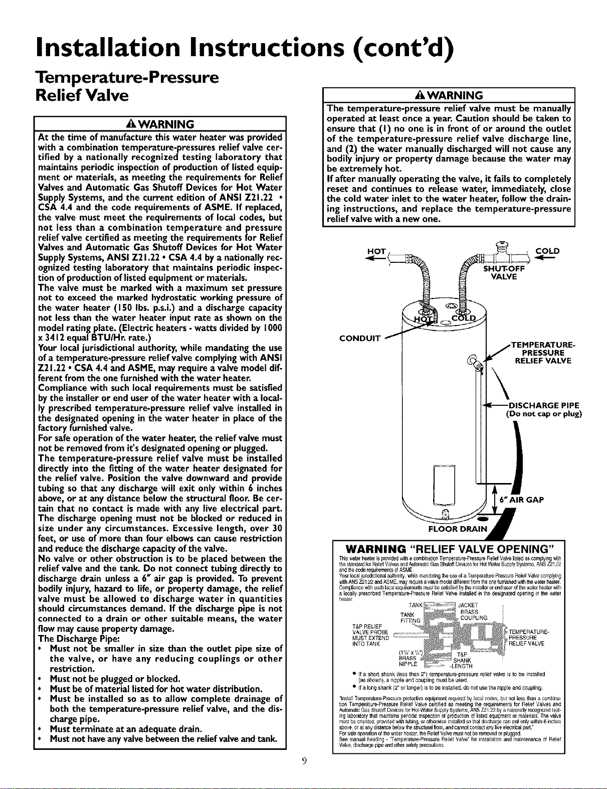
HOT COLD
SHUT-OFF
VALVE
CONDUIT
PRESSURE
RELIEF VALVE
(Do not cap or plug)
6_AIR GAP
WARNING "RELIEF VALVE OPENING"
Thiswatelheaterispr0v_ wiL_a corn_na_0nTempela_re_PiessureRstiefVa_e lisl_ asc0mp_i_g_
thestande_dfo_RelstfVa_esandA_lomaBcGasShuloflDe_lcesfor HotWaterSupp_Systems,ANSZ2122
an=3[hecodereqstrementsOfASME
Y0UlI_st i_Ilsd_0IlaJ a_[holity,w_lem_;statirlgthe_seof a Tempela_le_P_ssureRSt_ Vstvecon'_y_ng
withANS212122 andASME,mayrequirea valvemodeld_ffe_entfromtheoP_ft_r_sl_dw_ththe waea_heater
C0mpi_e w_hSUCh_caJl_,de_:nenlsmust be_t_ed byt_e_stst_eror _J U,_P,_Ofthew_telheat_ w_
_o_l_/pre_ci_be_T_psratur_Press_re Rel_f Vstve i;islalstd in _ designatedop_ir_g in the water
_tel
T&P RELIEF
VALVE PROBE
MUST EXTEND
INTOTANK
• if a short shank (less than 2) tempei_ture*pressule relief valve is to be instalstd
(assflown), a nipple_c_ coul31ingm_st be used¸
• ifa_ongshank (2_or _ongel) isto be installed,do _ot t_sethe nipple _nd cotJpling
Forsafeope[atstrlofthewate_deate_,the Re,ofVstvemust r_ofbe removedor plu_ged
see manual dead_g • 'Tempelat_re•Pless_re Relief Vstve_for i_sta_latio_an_mair_te_anceof Relief
Vstve,discha_;epipean_othel saletyprecaut_or_s
9
Loading ...
Loading ...
Loading ...