E L I T E
TM
Gas Dryer
Secadora de Gas
8519320A Sears Roebuck and Co., Hoffman Estates, IL 60179 U.S.A. www.sears.com
TABLE OF CONTENTS
WARRANTY ..................................................................................... 2
PEDESTAL OPTION WARRANTY ................................................. 2
DRYER SAFETY .............................................................................. 3
INSTALLATION INSTRUCTIONS .................................................. 5
Tools and Parts ............................................................................ 5
Optional Pedestal ......................................................................... 5
Location Requirements ............................................................... 5
Electrical Requirements ................................................................ 7
Gas Supply Requirements ........................................................... 7
Venting Requirements .................................................................. 8
Plan Vent System ......................................................................... 9
Install Vent System .................................................................... 10
Install Leveling Legs .................................................................. 11
Level Dryer................................................................................. 11
Make Gas Connection ............................................................... 11
Connect Vent ............................................................................. 12
Reverse Door Swing .................................................................. 12
Complete Installation ................................................................. 13
FEATURES AND BENEFITS ....................................................... 14
Automatic Temperature Control ................................................ 14
Jeans Cycle ............................................................................... 14
Ultra Delicate ............................................................................. 14
DRYER USE ................................................................................. 14
Starting Your Dryer .................................................................... 14
Stopping Your Dryer .................................................................. 15
Pausing or Restarting ................................................................ 15
Control Locked .......................................................................... 15
Leading ...................................................................................... 15
Drying and Cycle Tips ............................................................... 15
Status Lights .............................................................................. 16
Cycles ........................................................................................ 16
Options ...................................................................................... 17
Modifiers .................................................................................... 17
Changing Cycles, Options and Modifiers ................................. 18
End of Cycle Signal ................................................................... 18
TUMBLE FREF MHeated Dryer Rack ....................................... 18
DRYER CARE .............................................................................. 19
Cleaning the Dryer Location ...................................................... 19
Cleaning the Lint Screen ........................................................... 19
Cleaning the Dryer Interior ........................................................ 20
Removing Accumulated Lint ..................................................... 20
Vacation and Moving Care ........................................................ 20
Changing the Drum Light .......................................................... 20
TROUBLESHOOTING .................................................................. 20
PROTECTION AGREEMENTS .................................................... 21
SERVICE NUMBERS ............................................... BACK COVER
WARRANTY
Full One-Year Warranty on Mechanical and Bectrical Parts
For one year from the date of purchase, when this dryer is
installed and operated according to the instructions provided in
this Use and Care Guide, Sears will repair this dryer, free of
charge, if defective in materials or workmanship.
NOTE: Exhausting this dryer with a plastic vent can void this
warranty. See "Installation Instructions" for the complete exhaust
requirements for this dryer.
Limited Two-Year Warranty on SENSOR SMART TM
Electronic Control Board
For the second year from the date of purchase, Sears will replace
the electronic control board if defective in material or
workmanship. You will be charged for labor after the first year.
Warranty Restriction
If the dryer is subject to other than private family use, the above
warranty coverage is effective for only 90 days.
Warranty Service
Warranty service is available by contacting the nearest Sears
Service Center. This warranty applies only while the product is in
use in the United States.
This warranty gives you specific legal rights and you may also
have other rights which vary from state to state.
For Sears Warranty information or to contact a Sears Service
Center, please refer to the service numbers located on the back
page of this manual.
Sears, Roebuck and Co.
D/817WA, Hoffman Estates, IL 60179
Product Record
In the space following, record your complete model number,
serial number, and purchase date.You can find this information
on the model and serial number label, located at the top inside
dryer door well.
Have this information available to help you quickly obtain
assistance or service when you contact Sears concerning your
appliance.
Model number 110_
Serial number
Purchase date
Save these instructions and your sales receipt for future
reference.
PEDESTAL OPTION
WARRANTY
Full One-Year Warranty on Mechanical Parts
For one year from the date of purchase, supplier will repair or
replace any of its mechanical parts if defective in material or
workmanship. This Pedestal must be installed with this dryer
according to the instructions provided in the Pedestal Installation
Instructions.
Warranty Restriction
If the Pedestal is subject to other than private family use and/or
used with any other product than those listed in the installation
instructions, this warranty is null and void.
In the space following, record your complete model number,
serial number, and purchase date.You can find this information
on the model and serial number label.
Have this information available to help you quickly obtain
assistance or service when you contact Sears concerning your
appliance.
Model number 110_
Serial number
Purchase date
Save these instructions and your sales receipt for future
reference.
2
DRYER SAFETY
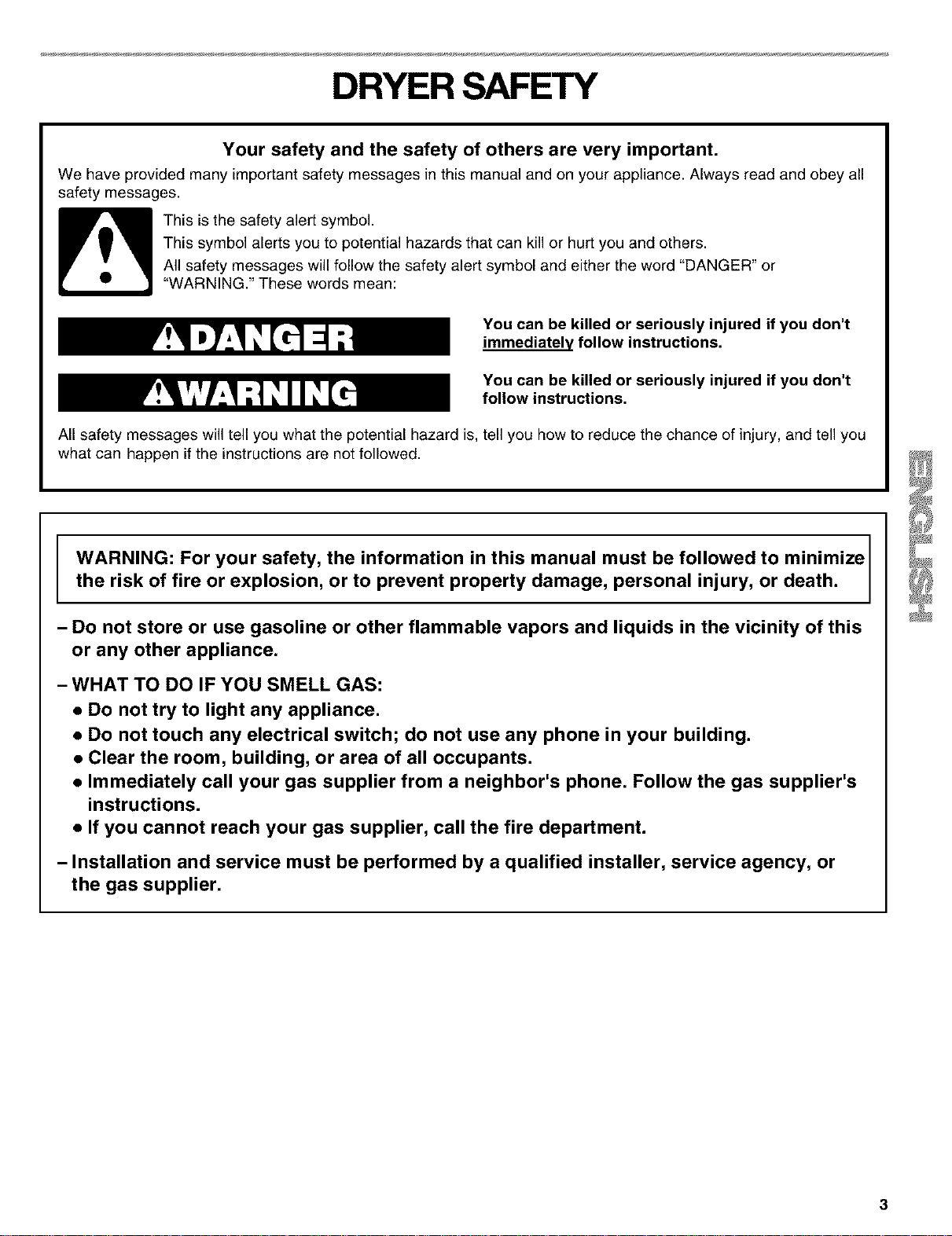
Your safety and the safety of others are very important.
We have provided many important safety messages in this manual and on your appliance. Always read and obey all
safety messages.
This is the safety alert symbol.
This symbol alerts you to potential hazards that can kill or hurt you and others.
All safety messages will follow the safety alert symbol and either the word "DANGER" or
"WARNING." These words mean:
You can be killed or seriously injured if you don't
immediately follow instructions.
You can be killed or seriously injured if you don't
follow instructions,
All safety messages will tell you what the potential hazard is, tell you how to reduce the chance of injury, and tell you
what can happen if the instructions are not followed.
WARNING: For your safety, the information in this manual must be followed to minimize
the risk of fire or explosion, or to prevent property damage, personal injury, or death.
- Do not store or use gasoline or other flammable vapors and liquids in the vicinity of this
or any other appliance.
- WHAT TO DO IF YOU SMELL GAS:
• Do not try to light any appliance.
• Do not touch any electrical switch; do not use any phone in your building.
• Clear the room, building, or area of all occupants.
• Immediately call your gas supplier from a neighbor's phone. Follow the gas supplier's
instructions.
• If you cannot reach your gas supplier, call the fire department.
- Installation and service must be performed by a qualified installer, service agency, or
the gas supplier.
IMPORTANT SAFETY INSTRUCTIONS
WARNING: To reduce the risk of fire, electric shock, or injury to persons when using the dryer, follow basic
precautions, including the following:
• Read all instructions before using the dryer.
• Do not place items exposed to cooking oils in
your dryer. Items contaminated with cooking oils
may contribute to a chemical reaction that could
cause a load to catch fire.
• Do not dry articles that have been previously
cleaned in, washed in, soaked in, or spotted with
gasoline, dry-cleaning solvents, other flammable,
or explosive substances as they give oft vapors
that could ignite or explode.
• Do not allow children to play on or in the dryer.
Close supervision of children is necessary when
the dryer is used near children.
• Before the dryer is removed from service or dis-
carded, remove the door to the drying compart-
ment.
• Do not reach into the dryer if the drum is moving.
• Do not install or store the dryer where it will be
exposed to the weather.
• Do not tamper with controls.
• Do not repair or replace any part of the dryer or
attempt any servicing unless specifically recom-
mended in this Use and Care Guide or in published
user-repair instructions that you understand and have
the skills to carry out.
• Do not use fabric softeners or products to eliminate
static unless recommended by the manufacturer of
the fabric softener or product.
• Do not use heat to dry articles containing foam rubber
or similarly textured rubberqike materials.
• Clean lint screen before or after each load.
• Keep area around the exhaust opening and adjacent
surrounding areas free from the accumulation of lint,
dust, and dirt.
• The interior of the dryer and exhaust vent should be
cleaned periodically by qualified service personnel.
• See installation instructions for grounding require-
ments.
SAVE THESE INSTRUCTIONS
IMPORTANT: The gas installation must conform with local codes, or in the absence of local codes, with the National
Fuel Gas Code, ANSI Z223.1/NFPA 54.
The dryer must be electrically grounded in accordance with local codes, or in the absence of local codes, with the
National Electrical Code, ANSI/NFPA 70.
4

INSTALLATION
INSTRUCTIONS
s Re 5ss s
Are you placing the dryer on a pedestal? You can purchase a
pedestal separately for this dryer. This pedestal will add about
14 in. (35.56 em) to the height of your unit for a total height of
approximately 52 in. (132.08 era).
Check that you have everything necessary for correct installation.
Proper installation is your responsibility.
• 8in. or 10 in. pipe wrench • Knife
• 8 in. or 10 in. adjustable • Safety glasses
wrench (for gas
connections) • Duct tape
• Flat-blade screwdriver • Pipe-joint compound
resistant to L.R gas
• Adjustable wrench that
opens to 1 in. (2.54 cm) • Caulking gun and
or hex-head socket compound (for installing
wrench (for adjusting new exhaust vent)
dryer feet) • Gloves
• Level • Pliers
• Y4in. nut driver or socket
wrench
Parts supplied
Remove parts package from dryer drum. Check that all parts
were included.
4 Levelinglegs
NOTE: Do not use leveling legs if installing the dryer on a
pedestal.
Parts needed
Check local codes and with gas supplier. Check existing gas
supply, electrical supply and venting. Read "Electrical
Requirements," "Gas Supply Requirements" and "Venting
Requirements" before purchasing parts.
• For close-clearance installations between 31.5 in. (80.01 cm)
and 37 in. (93.98 cm), see "Plan Vent System" section for
venting requirements.
I< 87,, >1
(93.98 ¢m)
Mobile home installations require special parts (listed following)
available for purchase from your local Sears store or Sears
Service Center. For further information, please call
1-800-4-MY-HOME _ (1-800-469-4663).
• Mobile Home Installation Kit. Ask for Part Number 346764.
• Metalexhaust system hardware.
Optional pedestal
The pedestal is available in three colors
White - Part Number 42842
Biscuit - Part Number 42844
Graphite - Part Number 42846
To order, call your local Sears store. For further information,
please call 1-800-4-MY-HOME _ (1-800-469-4663).
Lee@:on
u el
Explosion Hazard
Keep flammable materials and vapors, such as
gasoline, away from dryer.
Place dryer at least 18 inches (46 cm) above the
floor for a garage installation.
Failure to do so can result in death, explosion,
or fire.
You will need
• A location that allows for proper exhaust installation. A gas
dryer must be exhausted to the outdoors. See "Venting
Requirements."
• A grounded electrical outlet located within 2 ft (61 cm) of
either side of the dryer. See "Electrical Requirements."
• A sturdy floor to support the total dryer weight of 200 Ibs
(90.7 kg). The combined weight of a companion appliance
should also be considered.
A level floor with a maximum slope of 1 in. (2.5 cm) under
entire dryer. (If slope is greater than 1 in. [2.5 cm], install
Extended Dryer Feet Kit, Part No. 279816.) Clothes may not
tumble properly and automatic sensor cycles may not
operate correctly if dryer is not level.
• For a garage installation, you will need to place the dryer at
least 18 in. (46 cm) above the floor. If using a pedestal, you
will need an additional 6 in. (15.24 cm).
Donotoperateyourdryerattemperaturesbelow45°F(7°C).At
lowertemperatures,thedryermightnotshutoffattheendofan
automaticcycle.Dryingtimescanbeextended.
Thelaundrycentermustnotbeinstalledorstoredinanarea
whereitwillbeexposedtowaterand/orweather.
Checkcoderequirements.Somecodeslimit,ordonotpermit,
installationofthedryeringarages,closets,mobilehomes,or
sleepingquarters.Contactyourlocalbuildinginspector.
NOTE:Nootherfuel-burningappliancecanbeinstalled in the
same closet as a dryer.
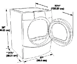
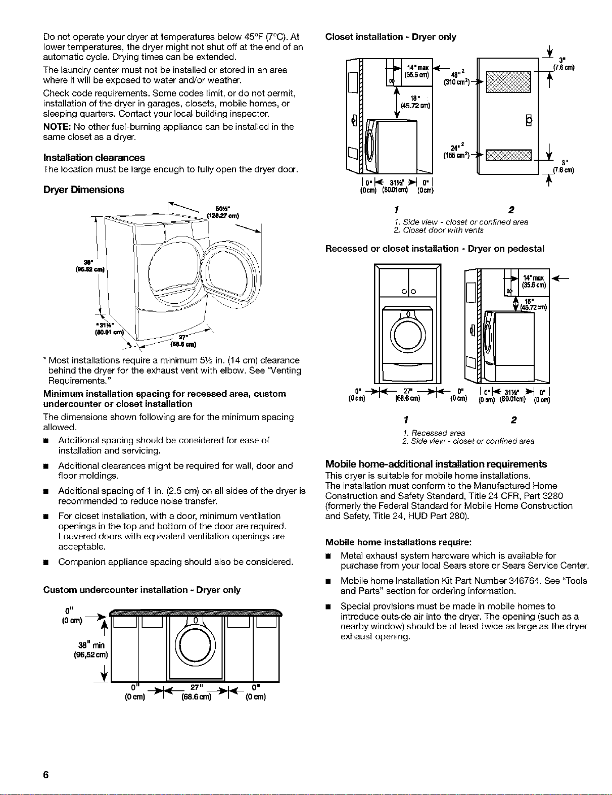
Installation clearances
The location must be large enough to fully open the dryer door.
Dryer Dimensions
(1Z.27 ¢rn)
* Most installations require a minimum 51/2in. (14 cm) clearance
behind the dryer for the exhaust vent with elbow. See '_/enting
Requirements."
Minimum installation spacing for recessed area, custom
undereountar or closet installation
The dimensions shown following are for the minimum spacing
allowed.
• Additional spacing should be considered for ease of
installation and servicing.
Additional clearances might be required for wall, door and
floor moldings.
Additional spacing of 1 in. (2.5 cm) on all sides of the dryer is
recommended to reduce noise transfer.
For closet installation, with a door, minimum ventilation
openings in the top and bottom of the door are required.
Louvered doors with equivalent ventilation openings are
acceptable.
• Companion appliance spacing should also be considered.
Custom undercounter installation +Dryer only
0 II
I I
38"rain
(96,52c_
0II 27" 0 II
Closet installation - Dryer only
Io. am" o.
IOcrnl(80.01_1 (0_)
#
+
3"
(7.6cm)
__(7.6cm)
1 2
I Side view - closet or confined area
2. Closet door with vents
Recessed or closet installation - Dryer on pedestal
olo
0" 27" 0"
(ocm)->_--lm.6_-->1<-(6 am)
Io'1"<-31_" _ o'1
(Ocm) (80.01crn) (Ocm)
1 2
1,Recessedarea
2+Side view - closet or confined area
Mobile home=additional installation requirements
This dryer is suitable for mobile home installations.
The installation must conform to the Manufactured Home
Construction and Safety Standard, Title 24 CFR, Part 3280
(formerly the Federal Standard for Mobile Home Construction
and Safety, Title 24, HUD Part 280).
Mobile home installations require:
• Metal exhaust system hardware which is available for
purchase from your local Sears store or Sears Service Center.
• Mobile home Installation Kit Part Number 346764. See "Tools
and Parts" section for ordering information.
Special provisions must be made in mobile homes to
introduce outside air into the dryer. The opening (such as a
nearby window) should be at least twice as large as the dryer
exhaust opening.
6
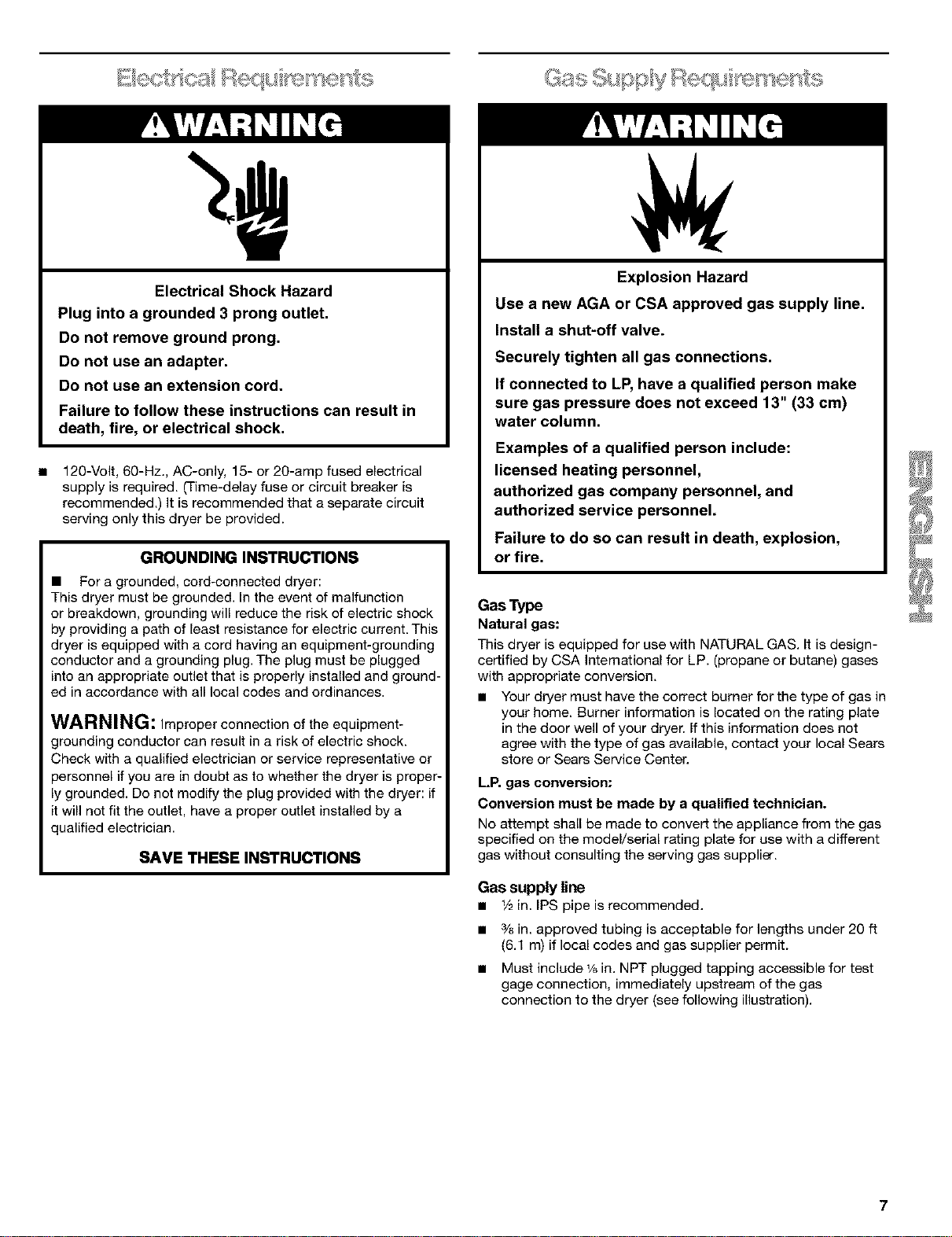
Electrical Shock Hazard
Plug into a grounded 3 prong outlet.
Do not remove ground prong.
Do not use an adapter.
Do not use an extension cord.
Failure to follow these instructions can result in
death, fire, or electrical shock.
120-Volt, 60-Hz., AC-only, 15- or 20-amp fused electrical
supply is required. (Time-delay fuse or circuit breaker is
recommended.) It is recommended that a separate circuit
serving only this dryer be provided.
GROUNDING INSTRUCTIONS
• For a grounded, cord-connected dryer:
This dryer must be grounded. In the event of malfunction
or breakdown, grounding will reduce the risk of electric shock
by providing a path of least resistance for electric current. This
dryer is equipped with a cord having an equipment-grounding
conductor and a grounding plug. The plug must be plugged
into an appropriate outlet that is properly installed and ground-
ed in accordance with all local codes and ordinances.
WARNING: Improper connection of the equipment-
grounding conductor can result in a risk of electric shock.
Check with a qualified electrician or service representative or
personnel if you are in doubt as to whether the dryer is proper-
ly grounded. Do not modify the plug provided with the dryer: if
it will not fit the outlet, have a proper outlet installed by a
qualified electrician.
SAVE THESE INSTRUCTIONS
Explosion Hazard
Use a new AGA or CSA approved gas supply line.
Install a shut-off valve.
Securely tighten all gas connections.
If connected to LP, have a qualified person make
sure gas pressure does not exceed 13" (33 cm)
water column=
Examples of a qualified person include:
licensed heating personnel,
authorized gas company personnel, and
authorized service personnel.
Failure to do so can result in death, explosion,
or fire.
Gas Type
Natural gas:
This dryer is equipped for use with NATURAL GAS. It is design-
certified by CSA International for LP. (propane or butane) gases
with appropriate conversion.
• Your dryer must have the correct burner for the type of gas in
your home. Burner information is located on the rating plate
in the door well of your dryer. If this information does not
agree with the type of gas available, contact your local Sears
store or Sears Service Center.
LP. gas conversion:
Conversion must be made by a qualified technician.
No attempt shall be made to convert the appliance from the gas
specified on the model/serial rating plate for use with a different
gas without consulting the serving gas supplier.
Gas supply line
• 1/2in. IPSpipe isrecommended.
• 3/8in. approved tubing is acceptable for lengths under 20 ft
(6.1 m) if local codes and gas supplier permit.
• Must include v6 in. NPT plugged tapping accessible for test
gage connection, immediately upstream of the gas
connection to the dryer (see following illustration).
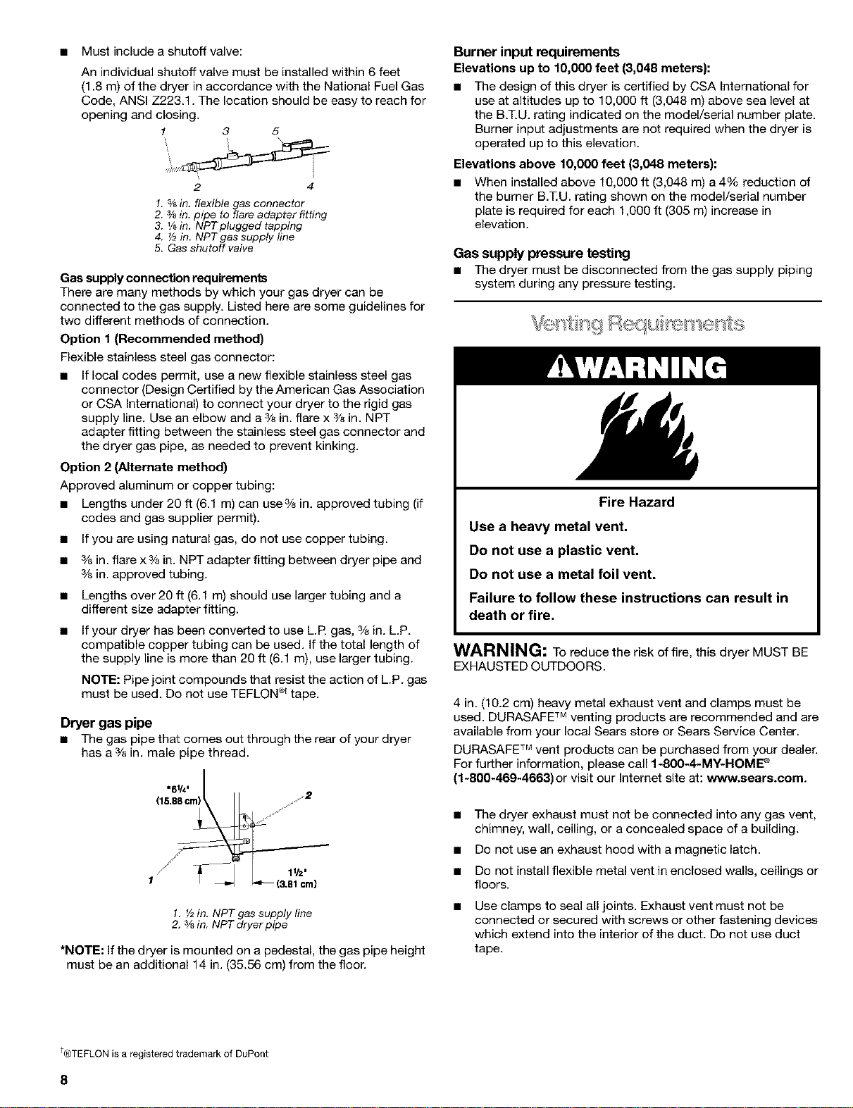
• Mustincludeashutoffvalve:
Anindividualshutoffvalvemustbeinstalledwithin6feet
(1.8m)ofthedryerinaccordancewiththeNationalFuelGas
Code,ANSIZ223.1.Thelocationshouldbeeasytoreachfor
openingandclosing.
1 3 5
2 4
1, s/3in. flexible gas connector
2. 3/8in. pipe to flare adapter fitting
3. Ysin. NPT ptugged tapping
4. _/2in. NPT gas supply line
5. Gas shutoff valve
Gas supply connection requirements
There are many methods by which your gas dryer can be
connected to the gas supply. Listed here are some guidelines for
two different methods of connection.
Option 1 (Recommended method)
Flexible stainless steel gas connector:
• If local codes permit, use a new flexible stainless steel gas
connector (Design Certified by the American Gas Association
or CSA International) to connect your dryer to the rigid gas
supply line. Use an elbow and a 3/8in. flare x 3/8in. NPT
adapter fitting between the stainless steel gas connector and
the dryer gas pipe, as needed to prevent kinking.
Option 2 (Alternate method)
Approved aluminum or copper tubing:
• Lengths under 20 ff (6.1 m) can use 3/8in. approved tubing (if
codes and gas supplier permit).
• If you are using natural gas, do not use copper tubing.
• 3/8in. flare x 3/8in. NPT adapter fitting between dryer pipe and
3/sin. approved tubing.
• Lengths over 20 ft (6.1 m) should use larger tubing and a
different size adapter fitting.
• If your dryer has been converted to use L.FLgas, 3/8in. L.P.
compatible copper tubing can be used. If the total length of
the supply line is more than 20 ft (6.1 m), use larger tubing.
NOTE: Pipe joint compounds that resist the action of LP. gas
must be used. De net use TEFLON _ tape.
Dryer gas pipe
• The gas pipe that comes out through the rear of your dryer
has a 3/8in. male pipe thread.
-61/4,
(15.88cm)
1 (3.81cm)
1. _/2in. NPT gas supply line
2. 3/3in NPT dryer pipe
*NOTE: If the dryer is mounted on a pedestal, the gas pipe height
must be an additional 14 in. (35.56 cm) from the floor.
Burner input requirements
Elevations up to 10,0(30 feet (3,048 meters):
• The design of this dryer is certified by CSA International for
use at altitudes up to 10,000 ft (3,048 m) above sea level at
the B.T.U. rating indicated on the model/serial number plate.
Burner input adjustments are not required when the dryer is
operated up to this elevation.
Elevations above 10,000 feet (3,048 meters):
• When installed above 10,000 ft (3,048 m) a 4% reduction of
the burner B.]_U. rating shown on the model/serial number
plate is required for each 1,000 ft (305 m) increase in
elevation.
Gas supply pressure testing
• The dryer must be disconnected from the gas supply piping
system during any pressure testing.
Fire Hazard
Use a heavy metal vent.
Do not use a plastic vent.
Do not use a metal foil vent.
Failure to follow these instructions can result in
death or fire.
WARNING: To reduce the risk of fire, this dryer MUST BE
EXHAUSTED OUTDOORS.
4 in. (10.2 cm) heavy metal exhaust vent and clamps must be
used. DURASAFE TM venting products are recommended and are
available from your local Sears store or Sears Service Center.
DURASAFE TM vent products can be purchased from your dealer.
For further information, please call 1-800-4-MY-HOME _
(1-800-469-4663) or visit our Internet site at: www.sears.com.
• The dryer exhaust must not be connected into any gas vent,
chimney, wall, ceiling, or a concealed space of a building.
• De net use an exhaust hood with a magnetic latch.
• De net install flexible metal vent in enclosed walls, ceilings or
floors.
Use clamps to seal all joints. Exhaust vent must not be
connected or secured with screws or other fastening devices
which extend into the interior of the duct. Do not use duct
tape.
t®TEFLON is a registered trademark of DuPont
8
IMPORTANT: Observe all governing codes and ordinances.
Improper venting can cause moisture and lint to collect
indoors, which may result in:
• Moisture damage to woodwork, furniture, paint, wall-
paper, carpets, etc.
• Housecleaning problems and health problems.
Use a heavy metal vent. Do not use plastic or metal foil vent.
Rigid metal vent is recommended to prevent crushing and
kinking.
Flexible metal vent must be fully extended and supported when
the dryer is in its final position. Remove excess flexible metal vent
to avoid sagging and kinking that may result in reduced airflow
and poor performance.
An exhaust hood should cap the vent to prevent rodents and
insects from entering the home.
Exhaust hood must be at least 12 in. (30.5 cm) from the ground or
any object that may be in the path of the exhaust (such as
flowers, rocks or bushes, etc.).
If using an existing vent system, clean lint from the entire length
of the system and make sure exhaust hood is not plugged with
lint. Replace any plastic or metal foil vent with rigid metal or
flexible metal vent.
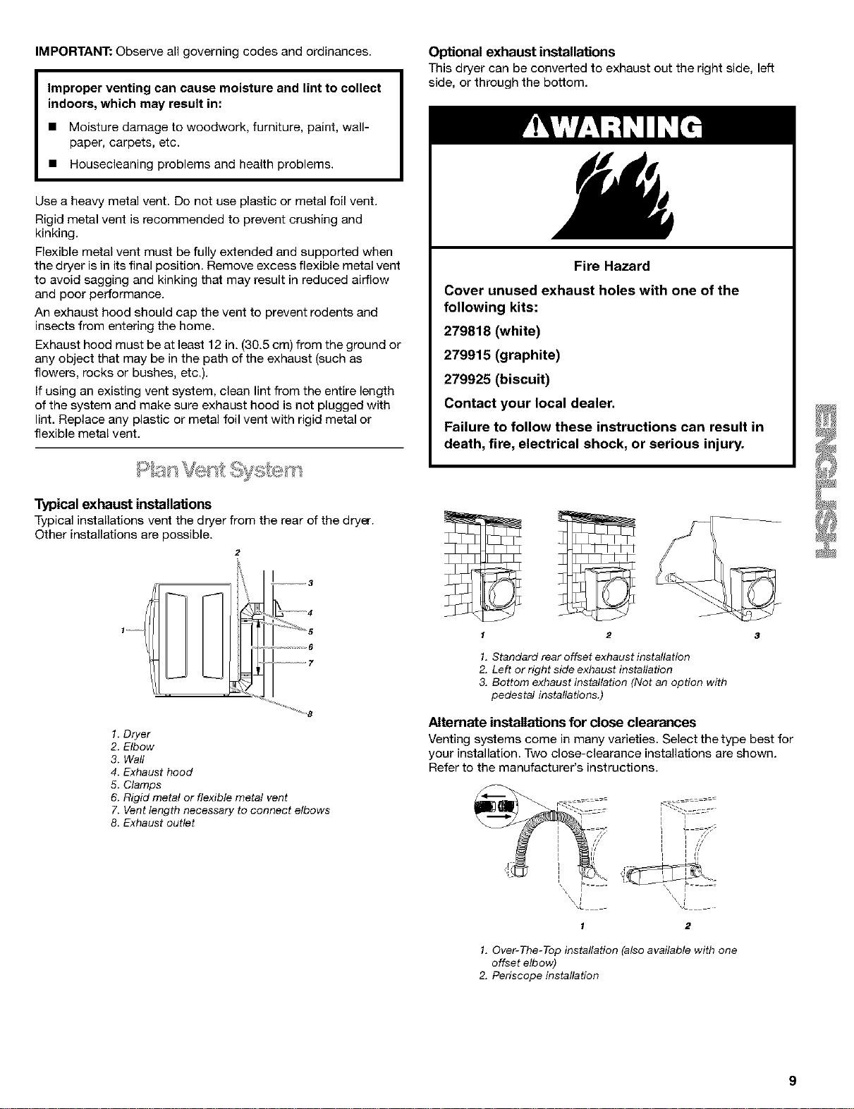
Optional exhaust installations
This dryer can be converted to exhaust out the right side, left
side, or through the bottom.
Fire Hazard
Cover unused exhaust holes with one of the
following kits:
279818 (white)
279915 (graphite)
279925 (biscuit)
Contact your local dealer.
Failure to follow these instructions can result in
death, fire, electrical shock, or serious injury.
Typical exhaust installations
Typical installations vent the dryer from the rear of the dryer.
Other installations are possible.
2
/ /
o
................ 6
.................... 7
1. Dryer
2. Elbow
3. Wall
4. Exhaust hood
5. Clamps
6. Rigid metal or flexible metal vent
7. Vent length necessary to connect elbows
8. Exhaust outlet
f 2
1. Standard rear offset exhaust installation
2. Left or right side exhaust installation
3. Bottom exhaust installation (Not an option with
pedestal installations.)
Alternate installations for close clearances
Venting systems come in many varieties. Select the type best for
your installation. Two close-clearance installations are shown.
Refer to the manufacturer's instructions.
XL XL
1 2
1. Over-The-Top installation (also available with one
offset elbow)
2. Periscope installation
NOTE: The following kits for close clearance alternate
installations are avaUable for purchase. For further information,
please call 1-800-4-MY-HOM E®(1-800-469-4663).
• Over-The-Top InstaUatien:
Part Number 26-49900
Periscope Installation (For use with dryer vent to wall vent
mismatch):
Part Number 26-49901 - Less than 5 in. (12.7 cm) mismatch
Part Number 26-49908 - 5 in. (12.7 cm) to 18 in. (45.72 cm)
mismatch
Part Number 26-49904 - 18 in. (45.72 cm) to 29 in. (73.66 cm)
mismatch
Part Number 26-49905 - 29 in. (73.66 cm) to 50 in. (127 cm)
mismatch
Special provisions for mobile home installations
The exhaust vent must be securely fastened to a noncombustible
portion of the mobile home structure and must not terminate
beneath the mobile home. Terminate the exhaust vent outside.
Determine Vent Length
1. Select the route that will provide the straightest and most
direct path outdoors. Plan the installation to use the fewest
number of elbows and turns. When using elbows or making
turns, allow as much room as possible. Bend vent gradually
to avoid kinking. Avoid 90° turns.
2. Determine vent length
The maximum length of the exhaust system depends upon:
• The type of vent (rigid metal or flexible metal).
• The number of elbows used.
• Type of hood.
Recommended hood styles are shown here.
2
(10.2 cm}
(10.2crn)
1.Louvered hood style
2. Box hood style
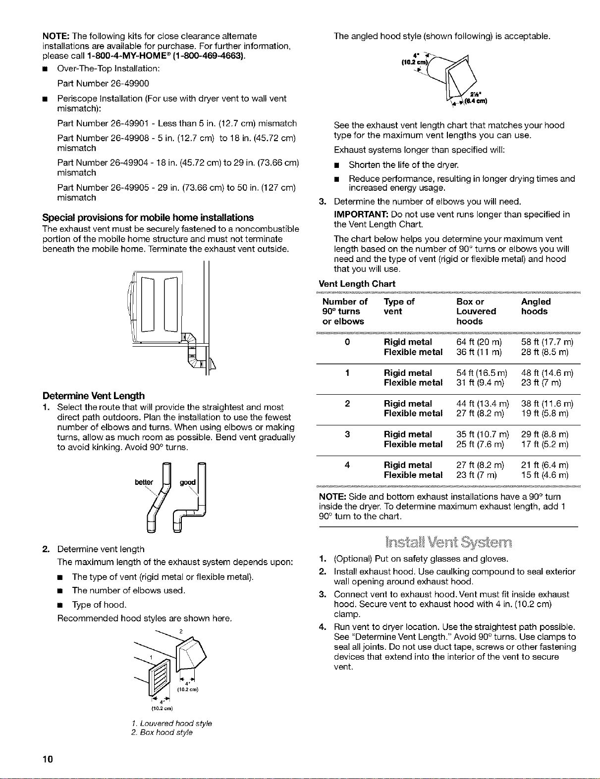
The angled hood style (shown following) is acceptable.
4"_
See the exhaust vent length chart that matches your hood
type for the maximum vent lengths you can use.
Exhaust systems longer than specified will:
• Shorten the life of the dryer.
• Reduce performance, resulting in longer drying times and
increased energy usage.
3. Determine the number of elbows you will need.
IMPORTANT: Do not use vent runs longer than specified in
the Vent Length Chart.
The chart below helps you determine your maximum vent
length based on the number of 99 ° turns or elbows you will
need and the type of vent (rigid or flexible metal) and hood
that you will use.
Vent Length Chart
Number of Type of Box or Angled
90° turns vent Louvered hoods
or elbows hoods
0 Rigid metal 64 ft (20 m) 58 ft (17.7 m)
Flexible metal 36 ft (11 m) 28 ft (8.5 m)
1 Rigid metal 54 ft (16.5 m) 48 ft (14.6 m)
Flexible metal 31 ft (9.4 m) 23 ft (7 m)
2 Rigid metal 44 ft (13.4 m) 38 ft (11.6 m)
Flexible metal 27 ft (8.2 m) 19 ft (5.8 m)
3 Rigid metal 35 ft (10.7 m) 29 ft (8.8 m)
Flexible metal 25 ft (7.6 m) 17 ft (5.2 m)
4 Rigid metal 27 ft (8.2 m) 21 ft (6.4 m)
Flexible metal 23 ft (7 m) 15 ft (4.6 m)
NOTE: Side and bottom exhaust installations have a 90° turn
inside the dryer. To determine maximum exhaust length, add 1
90° turn to the chart.
1. (Optional) Put on safety glasses and gloves.
2. Install exhaust hood. Use caulking compound to seal exterior
wall opening around exhaust hood.
3. Connect vent to exhaust hood. Vent must fit inside exhaust
hood. Secure vent to exhaust hood with 4 in. (10.2 cm)
clamp.
4. Run vent to dryer location. Use the straightest path possible.
See "Determine Vent Length." Avoid 90° turns. Use clamps to
seal all joints. Do not use duct tape, screws or other fastening
devices that extend into the interior of the vent to secure
vent.
10
L,,eveng Legs
Check the levelness of the dryer. Check levelness first
side-to-side, then front-to-back.
1. To protect the floor, use a large flat piece of cardboard from
the dryer carton. Place cardboard under the entire back edge
of the dryer. See illustration.
2. Firmly grasp the body of the dryer (not the conecle panel).
Gently lay the dryer on the cardboard.
8. Examine the leveling legs. Find the diamond marking.
4. Screw the legs into the leg holes by hand. Use a wrench to
finish turning the legs until the diamond marking is no longer
visible.
5. Place a carton corner post under each of the 2 dryer back
corners. Stand the dryer up. Slide the dryer on the corner
posts until it is close to its final location. Leave enough room
to connect the exhaust vent or gas line.
6. Once connection is made and dryer is in final location,
remove comer posts and cardboard.
For mobile home use
Gas dryers must be securely fastened to the floor at the time of
installation.
Mobile home installations require a Mobile Home Installation Kit.
For more information, please reference the service numbers
located on the back page of this manual.
If the dryer is not level, prop up the dryer using a wood block.
Use a wrench to adjust the legs up or down and check again for
levelness.
NOTE: It might be necessary to level the dryer again after it has
been moved into its final position.
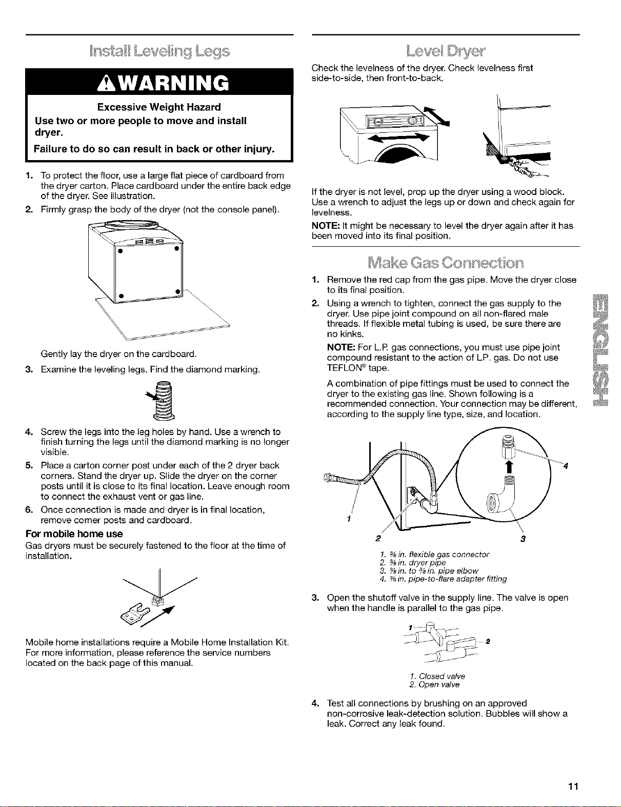
1.
2.
_,. ,_ . _ _ • _ . 2,_,_ ,
Ms<e Gas ÷ct <x
Remove the red cap from the gas pipe. Move the dryer close
to its final position.
Using a wrench to tighten, connect the gas supply to the
dryer. Use pipe joint compound on all non-flared male
threads. If flexible metal tubing is used, be sure there are
no kinks.
NOTE: For LP gas connections, you must use pipe joint
compound resistant to the action of LP. gas. De not use
TEFLON ®tape.
A combination of pipe fittings must be used to connect the
dryer to the existing gas line. Shown following is a
recommended connection. Your connection may be different,
according to the supply line type, size, and location.
!
1
1. _ in. flexible gas connector
2. _sin. dryer pipe
3, _8in. to _sin. pipe elbow
4. _in. pipe-to-flare adapter fitting
8. Open the shutoff valve in the supply line. The valve is open
when the handle is parallel to the gas pipe.
1. Closed valve
2. Open valve
4. Test all connections by brushing on an approved
non-corrosive leak-detection solution. Bubbles will show a
leak. Correct any leak found.
11
1. Using a 4 in. (10.2 cm) clamp, connect vent to exhaust outlet
in dryer. If connecting to existing vent, make sure the vent is
clean. The dryer vent must fit over the dryer exhaust outlet
and inside the exhaust hood. Make sure the vent is secured
to exhaust hood with a 4 in. (10.2 cm) clamp.
2. Move dryer into final position. Do not crush or kink vent.
Make sure dryer is level.
3. (On gas models) Check to be sure there are no kinks in the
flexible gas line.
Reverse the hinge and hinge cover
1. Place the inner door, screwhead side up, on the work space.
2. Gently pull the plastic cover out and down. This unsnaps the
plastic hinge cover from the inside door assembly.
You can change your door swing from a right-side opening to a
left-side opening, if desired.
Remove the door
1. Place a towel or soft cloth on top of the dryer or work space
to protect the surface.
2. Open the dryer door. Remove the 5 screws that hold the door
hinge on the front panel of the dryer. Loosen, but do not
remove, the screw with the top keyhole opening LAST (2nd
from the top).
\
3. Remove the 4 screws that hold the hinge to the door.
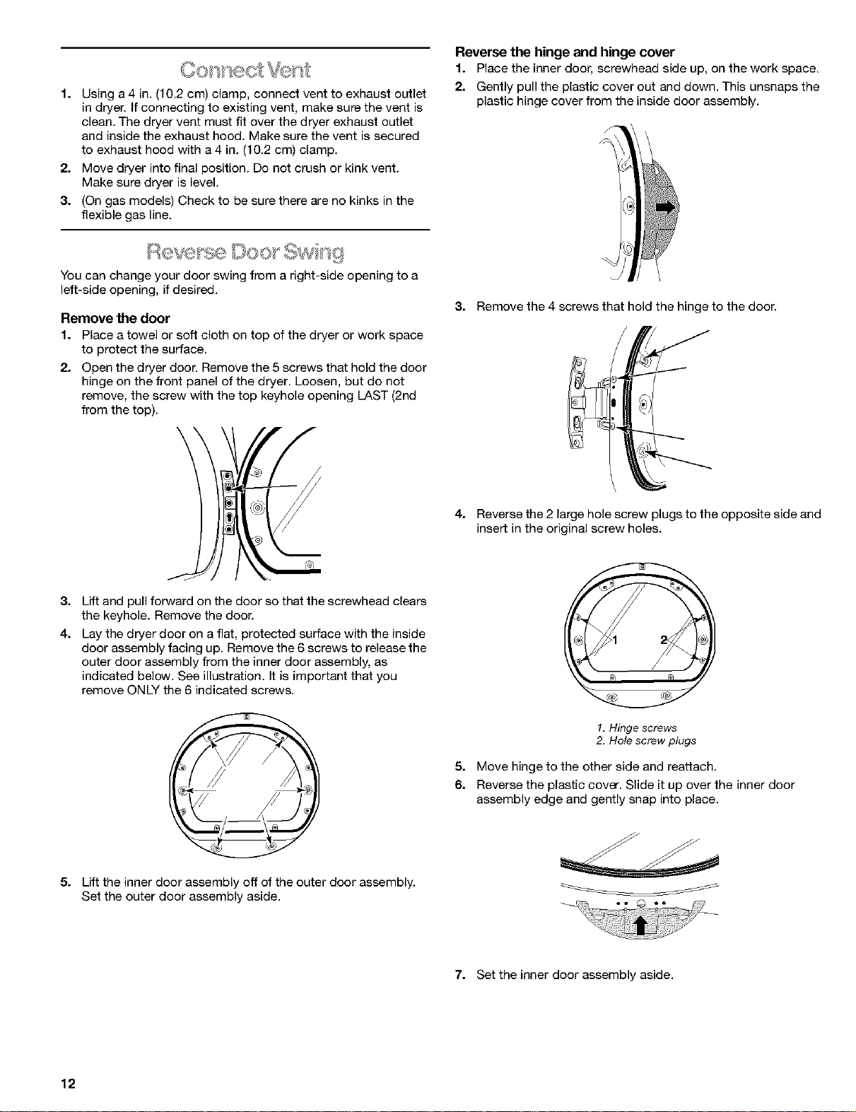
4. Reverse the 2 lane hole screw plugs to the opposite side and
insert in the original screw holes.
3. Lift and pull forward on the door so that the ecrewhead clears
the keyhole. Remove the door.
4. Lay the dryer door on a flat, protected surface with the inside
door assembly facing up. Remove the 6 screws to release the
outer door assembly from the inner door assembly, as
indicated below. See illustration. It is important that you
remove ONLY the 6 indicated screws.
5. Lift the inner door assembly off of the outer door assembly.
Set the outer door assembly aside.
1, Hinge screws
2. Hole screw plugs
5. Move hinge to the other side and reattach.
6. Reverse the plastic cover. Slide it up over the inner door
assembly edge and gently snap into place.
7. Set the inner door assembly aside.
12
Reverse the door handle
1. Place the outer door assembly face down on work space.
2. Remove the 2 screws that hold the door handle and the 2
screws holding the hole plugs. If hole plugs do not easily fall
out after screws are removec insert a small screwdriver into
the holes and gently push the plugs out.
\
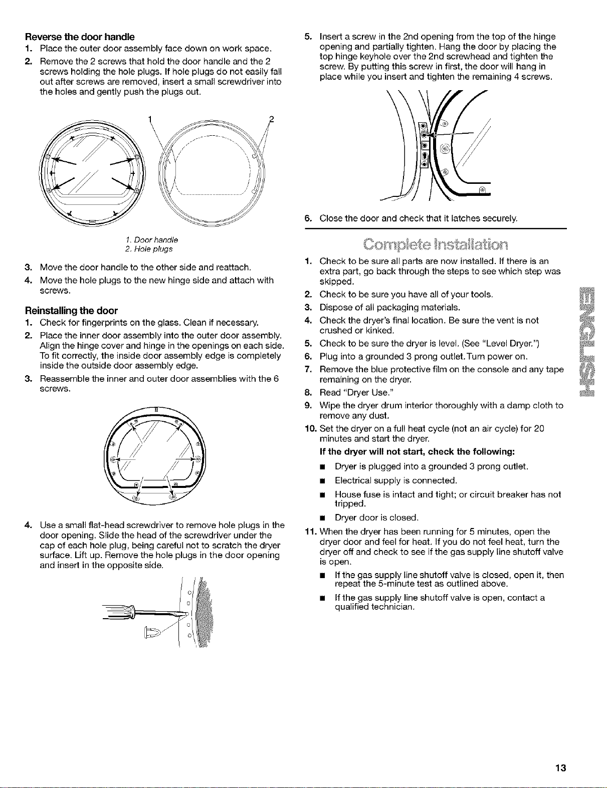
5. Insert a screw in the 2nd opening from the top of the hinge
opening and partially tighten. Hang the door by placing the
top hinge keyhole over the 2nd screwhead and tighten the
screw. By putting this screw in first, the door will hang in
place while you insert and tighten the remaining 4 screws.
\
1,Door handle
2. Hole plugs
3. Move the door handle to the other side and reattach.
4. Move the hole plugs to the new hinge side and attach with
screws.
Reinstalling the door
1. Check for fingerprints on the glass. Clean ff necessary.
2. Place the inner door assembly into the outer door assembly.
Align the hinge cover and hinge in the openings on each side.
To fit correctly, the inside door assembly edge is completely
inside the outside door assembly edge.
3. Reassemble the inner and outer door assemblies with the 6
screws.
41
Use a small flat-head screwdriver to remove hole plugs in the
door opening. Slide the head of the screwdriver under the
cap of each hole plug, being careful not to scratch the dryer
surface. Lift up. Remove the hole plugs in the door opening
and insert in the opposite side.
6. Close the door and check that it latches securely.
1. Check to be sure all parts are now installed, If there is an
extra part, go back through the steps to see which step was
skipped.
2. Check to be sure you have all of your tools.
3. Dispose of all packaging materials,
4. Check the dryer's final location. Be sure the vent is not
crushed or kinked.
5. Check to be sure the dryer is level. (See "Level Dryer.")
6. Plug into a grounded 3 prong outlet.Turn power on.
7. Remove the blue protective film on the console and any tape
remaining on the dryer.
8. Read "Dryer Use."
9. Wipe the dryer drum interior thoroughly with a damp cloth to
remove any dust.
10. Set the dryer on a full heat cycle (not an air cycle) for 20
minutes and start the dryer.
If the dryer will not start, check the following:
• Dryer is plugged into a grounded 3 prong outlet.
• Electrical supply is connected.
• House fuse is intact and tight; or circuit breaker has not
tripped.
• Dryer dooris closed.
11. When the dryer has been running for 5 minutes, open the
dryer door and feel for heat. If you do not feel heat, turn the
dryer off and check to see if the gas supply line shutoff valve
is open.
• If the gas supply line shutoff valve is closed, open it, then
repeat the 5-minute test as outlined above.
• If the gas supply line shutoff valve is open, contact a
qualified technician.
13
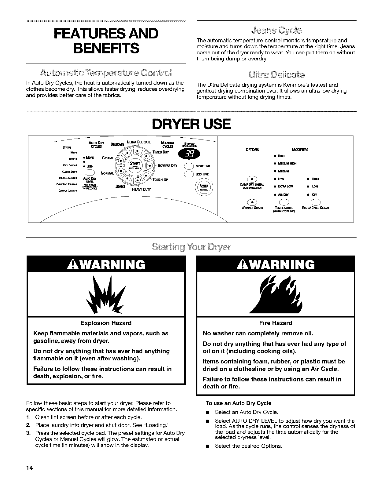
FEATURES AND
BENEFITS
In Auto Dry Cycles, the heat is automatically turned down as the
clothes become dry. This allows faster drying, reduces overdrying
and provides better care of the fabrics.
The automatic temperature control monitors temperature and
moisture and turns down the temperature at the right time. Jeans
come out of the dryer ready to wear. You can pat them on without
them being damp or overdry.
The Ultra Delicate drying system is Kenmore's fastest and
gentlest drying combination ever. It allows an ultra low drying
temperature without long drying times.
DRYER USE
Explosion Hazard
Keep flammable materials and vapors, such as
gasoline, away from dryer.
Do not dry anything that has ever had anything
flammable on it (even after washing).
Failure to follow these instructions can result in
death, explosion, or fire.
Fire Hazard
No washer can completely remove oil.
Do not dry anything that has ever had any type of
oil on it (including cooking oils).
Items containing foam, rubber, or plastic must be
dried on a clothesline or by using an Air Cycle.
Failure to follow these instructions can result in
death or fire.
Follow these basic steps to start your dryer. Please refer to
specific sections of this manual for more detailed information.
1. Clean lint screen before or after each cycle.
2. Place laundry into dryer and shut door. See "Loading."
3. Press the selected cycle pad. The preset settings for Auto Dry
Cycles or Manual Cycles will glow. The estimated or actual
cycle time (in minutes) will show in the display.
To use an Auto Dry Cycle
• Select an Auto Dry Cycle.
Select AUTO DRY LEVEL to adjust how dry you want the
load. As the cycle runs, the control senses the dryness of
the load and adjusts the time automatically for the
selected dryness level.
• Select the desired Options.
14
To make changes during an Auto Dry Cycle:
• Press PAUSE/CANCEL
• Adjust Auto Dry Level and/or Options.
NOTE: Auto Dry Level selections can only be made while
using Auto Dry Cycles. Selecting More or Less
automalcaly adjusts the sensed time needed.
• MORE
• LESS
AUTO DRY
LEVEL
PRESS&HOLD3
S_'OND5I_ LOCK/
UNLOa(CDNI_OL
To use a Manual Cycle
• Select a Manual Cycle.
Press MORE TIME or LESS TIME until the desired drying
time is displayed. Tap MORE TIME or LESS TIME and the
time will change by 1-minute intervals. Press and hold
MORE TIME or LESS TIME and the time will change by
5-minute intervals.
NOTE: The More Time and Less Time features can only
be used with Manual Cycles.
O MORETIME
(_ LESSlIME
• Press TEMPERATURE until the desired temperature
glows.
NOTE: During a Manual Cycle, you can change the settings
for Time, Temperature, WRINKLE GUARD _>and End of Cycle
Signal. Press PAUSE/CANCEL twice to stop the dryer and
clear the settings. Select another cycle or option.
4. (OPTIONAL STEP) If desired, select OPTIONS. For more
details, see "Options."
5. (OPTIONAL STEP) If desired, set the END of CYCLE SIGNAL.
Select HIGH or LOW to alert you when a cycle ends.
6. Press and hold START for approximately 3 seconds until
dryer starts. Be sure the door is closed.
• If you do not press Start within 5 minutes of selecting the
cycle, the dryer automatically shuts off.
• If you wish to end your drying cycle after pressing Start,
press PAUSE/CANCEL twice.
To stop your dryer at anytime
Press PAUSE/CANCELtwice or open the door.
To pause the dryer at anytime
Open the door or press PAUSE/CANCEL once.
TO restart the dryer
Close the door. Press and hold START until dryer starts.
NOTE: Drying will continue from where the cycle was interrupted
if you close the door and press Start within 5 minutes. If the cycle
is interrupted for more than 5 minutes, the dryer will shut off.
Select new cycle settings before restarting the dryer.
This feature allows you to lock your settings to prevent
unintended use of the dryer. You can also use the Control Locked
feature to prevent unintended cycle or option changes during
dryer operation.
To enable the Control Locked feature:
Press and hold AUTO DRY LEVEL for 3 seconds. Control Locked
glows and a single beep tone is heard. To unlock, press and hold
AUTO DRY LEVEL for 3 seconds. The indicator light turns off.
Properly loading your dryer can lower your utility bill and prolong
the life of your garments.
Loading suggestions
• Load the dryer by the amount of space items take up, not by
their weight.
• Do not overload the dryer. This causes uneven drying and
wrinkling.
Super Capacity Dryers
Heavy Work Clothes
4jeans 2 sweatpants
4 workpants 2 sweatshirts
4 workshirts
Towels
10 bath towels 14 washcloths
10 hand towels
Mixed Load
3 sheets (1 king, 2 twin) 9 T-shirts
4 pillowcases 9 shorts
3 shirts 10 handkerchiefs
3 blouses
Select the correct cycle and dryness level or temperature for your
load. If an Auto Dry Cycle is running, the display shows the
estimated cycle time when your dryer is automatically sensing
the dryness level of your load. If a Manual Cycle is running, the
display shows the exact number of minutes remaining in the
cycle.
Cool Down tumbles the load without heat during the last few
minutes of all cycles. Cool Down makes the loads easier to
handle and reduces wrinkling. The length of the Cool Down
depends on the load size and dryness level.
Drying tips
• Follow care label directions when they are available.
• If you use fabric softener sheets, use only ones labeled as
dryer safe. Follow package instructions.
• To reduce wrinkling, remove the load from the dryer as soon
as tumbling stops. This is especially important for permanent
press, knits, and synthetic fabrics.
• Avoid drying heavy work clothes together with lighter fabrics.
This could cause overdrying of lighter fabrics and their
increased shrinkage or wrinkling.
15
Cycle tips
• Dry most loads using the preset cycle settings.
• Refer to the Auto Dry or Manual Preset Cycle Settings chart
(in the "Cycles" section) for a guide to drying various loads.
Drying temperature and Auto Dry Level are preset when
you choose an Auto Dry Cycle.You can select a different
dryness level, depending on your load by pressing Auto
Dry Level and tapping More or Less.
If you wish to adjust the cycle length of a Manual Cycle,
press More Time or Less Time. Adjust the temperature of
a Manual Cycle by pressing Temperature until the desired
temperature is selected.
NOTE: You cannot choose an Auto Dry Level with Manual
Cycles.
_ S
Follow the progress of your dryer with the drying Status indicator
lights.
WET•
DAMP•
COOL DOWN •
CLOTHESDRY•
WRINKLEGUARD•
CHECKLINTSCREEN•
CON'mOL LOCKED•
Wet
The Wet light glows at the beginning of Auto Dry or Manual
cycles if a wet item is detected.
• In an Auto Dry Cycle, if a wet item is not detected after 5
minutes, the dryer goes directly into Cool Down and the Cool
Down and WRINKLE GUARD <_indicators glow, if selected.
• In a Manual Cycle, if a wet item is not detected, the dryer will
continue to run for the length of time selected, but the Wet
light will not glow.
Damp
The Damp light glows in an Auto Dry Cycle when the laundry is
approximately 80% dry. Damp Dry Signal beeps, if selected. (See
"Options.")
Cool Down
The Cool Down light glows during the cool down part of the
cycle. Laundry cools for ease in handling.
Clothes Dry
The Clothes Dry light glows when the drying cycle is finished.
This indicator stays on during WRINKLE GUARD ®.
WRINKLE GUARD ®
The WRINKLE GUARD _"_light glows when this option is selected.
This indicator stays on with Clothes Dry.
Check Lint Screen
The Check Lint Screen light reminds you to check the lint screen.
The light glows when the user selects a cycle. It goes out when
the door is opened, Start is pressed, or until 5 minutes elapses.
Corrlml Locked
The Control Locked light glows when this option isenabled.
Indicator lights
Other indicator lights show Cycle, Options, Modifiers and End of
Cycle settings selected. The display shows the estimated or
actual time remaining.
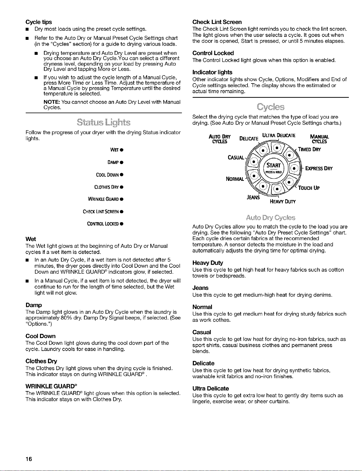
Select the drying cycle that matches the type of load you are
drying. (See Auto Dry or Manual Preset Cycle Settings charts.)
AUTODRY DELICATEULTRADEUCAIE MANUAL
CYQ.ES _ MEDDCRLES
NORMAL__k___i EXPRESSDl_t'
_TOUCHUP
JEANS
HEAVYDUTY
Auto Dry Cycles allow you to match the cycle to the load you are
drying. See the following "Auto Dry Preset Cycle Settings" chart.
Each cycle dries certain fabrics at the recommended
temperature. A sensor detects the moisture in the load and
automatically adjusts the drying time for optimal drying.
Heavy Duty
Use this cycle to get high heat for heavy fabrics such as cotton
towels or bedspreads.
Jeans
Usethis cycle to get medium-high heat for drying denims.
Normal
Use this cycle to get medium heat for drying sturdy fabrics such
as work cothee.
Casual
Use this cycle to get low heat for drying no-iron fabrics, such as
sport shirts, casual business clothes and permanent press
blends.
Delicate
Use this cycle to get low heat for drying synthetic fabrics,
washable knit fabrics and no-iron finishes.
Ultra Delicate
Use this cycle to get extra low heat to gently dry items such as
lingerie, exercise wear, or sheer curtains.
16
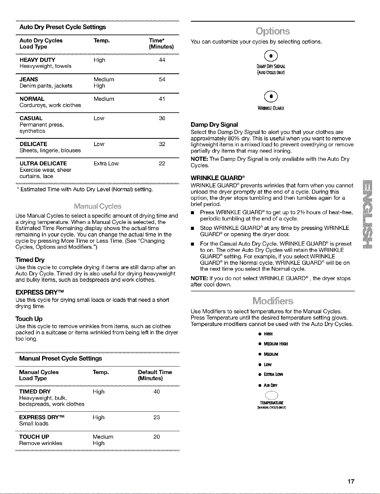
Auto Dry Preset Cycle Settings
Auto Dry Cycles Temp. Time*
Load Type (Minutes)
HEAVY DUTY High 44
Heavyweight, towels
JEANS Medium 54
Denim pants, jackets High
NORMAL Medium 41
Corduroys, work clothes
CASUAL Low 36
Permanent press,
synthetics
DELICATE Low 32
Sheets, lingerie, blouses
ULTRA DELICATE Extra Low 22
Exercise wear, sheer
curtains, lace
* Estimated Time with Auto Dry Level (Normal) setting.
Use Manual Cycles to select a specific amount of drying time and
a drying temperature. When a Manual Cycle is selected, the
Estimated Time Remaining display shows the actual time
remaining in your cycle. You can change the actual time in the
cycle by pressing More Time or Less Time. (See "Changing
Cycles, Options and Modifiers.")
Timed Dry
Use this cycle to complete drying if items are still damp after an
Auto Dry Cycle. Timed dry is also useful for drying heavyweight
and bulky items, such as bedspreads and work clothes.
EXPRESS DRY TM
Use this cycle for drying small loads or loads that need a short
drying time.
Touch Up
Use this cycle to remove wrinkles from items, such as clothes
packed in a suitcase or items wrinkled from being left in the dryer
too long.
Manual Preset Cycle Settings
Manual Cycles Temp. Default Time
Load Type (Minutes)
TIMED DRY High 40
Heavyweight, bulk,
bedspreads, work clothes
EXPRESS DRYTM High 23
Small loads
TOUCH UP Medium 20
Remove wrinkles High
You can customize your cycles by selecting options.
@
DAMPDRYSIGNAL
(AuToRYeso,Lvl
WRINI_EGUARD
Damp Dry Signal
Select the Damp Dry Signal to alert you that your clothes are
approximately 80% dry. This is useful when you want to remove
lightweight items in amixed load to prevent overdrying or remove
partially dry items that may need ironing.
NOTE: The Damp Dry Signal is only available with the Auto Dry
Cycles.
WRINKLE GUARD _
WRINKLE GUARD <_prevents wrinkles that form when you cannot
unload the dryer promptly at the end of a cycle. During this
option, the dryer stops tumbling and then tumbles again for a
brief period.
• Press WRINKLE GUARD <_to get up to 21/2hours of heat-free,
periodic tumbling at the end of a cycle.
• Stop WRINKLE GUARD'at any time by pressing WRINKLE
GUARD ®or opening the dryer door.
• For the Casual Auto Dry Cycle, WRINKLE GUARD _ is preset
to on. The other Auto Dry Cycles will retain the WRINKLE
GUARD ®setting. For example, if you select WRINKLE
GUARD ®in the Normal cycle, WRINKLE GUARD <'>will be on
the next time you select the Normal cycle.
NOTE: Ifyou do not select WRINKLE GUARD _">, the dryer stops
after cool down.
Use Modifiers to select temperatures for the Manual Cycles.
Press Temperature until the desired temperature setting glows.
Temperature modifiers cannot be used with the Auto Dry Cycles.
• HIDH
• MEDIUMHI6H
• MEDIUM
sLOW
• Exn_LOW
• AIRDRY
TEMPERA'PJRE
_NUAL CfCLESOffLY)
17
Air Dry
Use the Air Dry Modifier for items that require drying without heat
such as rubber, plastic and heat-sensitive fabrics. This chart
shows examples of items that can be dded using Air Dry.
Type of Load Time*
(Minutes)
Foam rubber - pillows, padded bras, stuffed toys 20 - 30
Plastic - Shower curtains, tablecloths 20 - 30
Rubber-backed rugs 40 - 50
Olefin, polypropylene, sheer nylon 10 - 20
* Reset cycle to complete drying, if needed.
When using Air Dry
• Check to see that coverings are securely stitched.
• Shake and fluff pillows by hand periodically during the cycle.
• Dry item completely. Foam rubber pillows are slow to dry.
NOTE: Air Dry is not available with Auto Dry Cycles.
a sd Moo f el,',u
You can change Auto Dry and Manual Cycles, Options and
Modifiers any time before pressing Start.
• Three short tones sound if an unavailable combination is
selected. The last selection will not be accepted.
Changing Cycles after pressing Start
1. Press PAUSE/CANCEL twice.
2. Select the desired cycle and options.
3. Press and hold START. The dryer starts at the beginning of
the new cycle.
NOTE: If you do not press Start within 5 minutes of selecting the
cycle, the dryer automatically shuts off.
Changing Options and Modifiers after pressing Start
You can change an Option or Modifier anytime before the
selected Option or Modifier begins.
1. Press PAUSE/CANCELonce.
2. Select the new Option and/or Modifiers.
3. Press and hold START to continue the cycle.
NOTE: If you happen to press Pause/Cancel twice, the program
clears and your dryer shuts down. Restart the selection process.
l! !l e = " ....
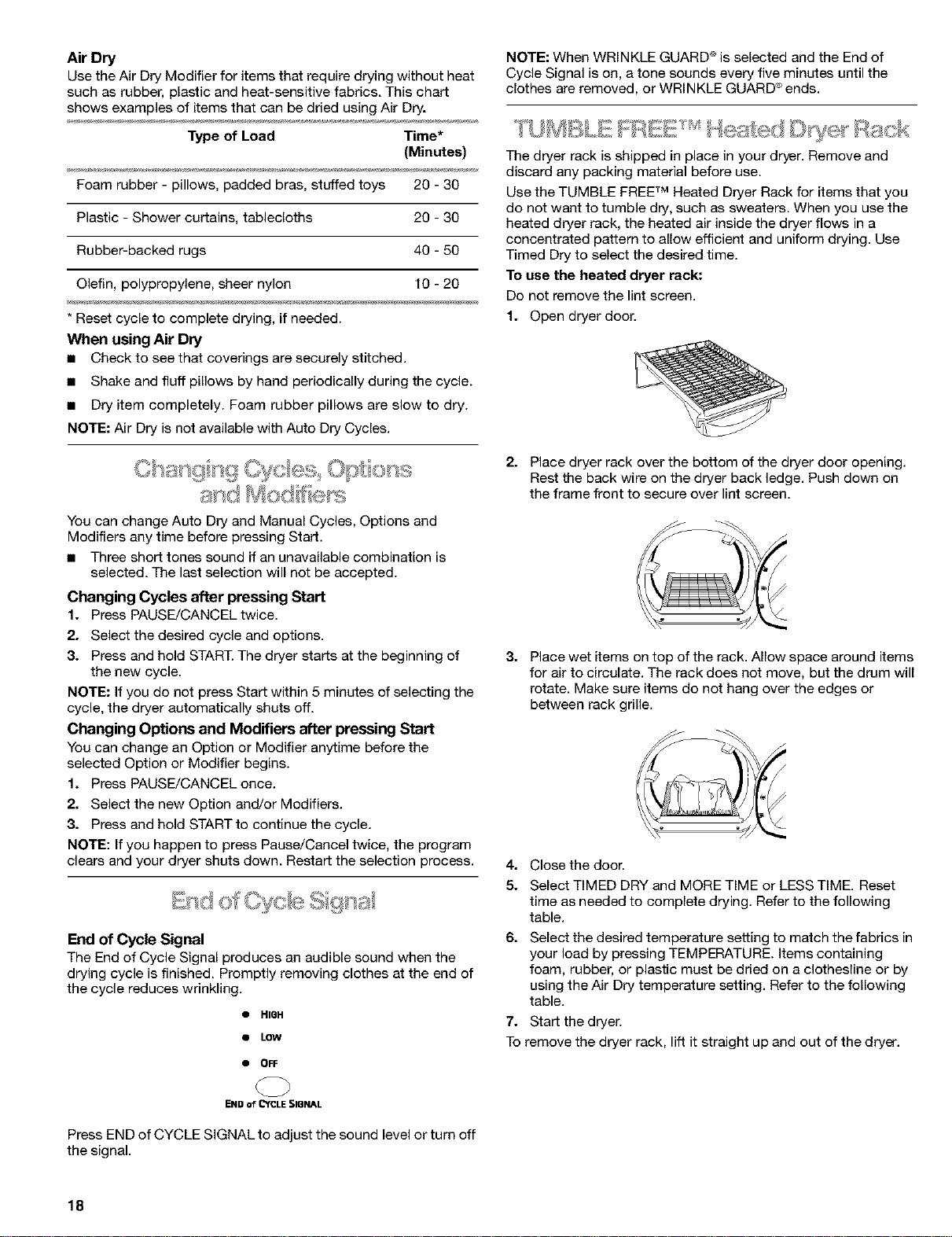
End of Cycle Signal
The End of Cycle Signal produces an audible sound when the
drying cycle is finished. Promptly removing clothes at the end of
the cycle reduces wrinkling.
• HIQH
• LOW
• OFF
NOTE: When WRINKLE GUARD ®is selected and the End of
Cycle Signal is on, a tone sounds every five minutes until the
clothes are removed, or WRINKLE GUARD ®ends.
U BLIs ;ssw'-s;:o bleate(: l<ack
The dryer rack is shipped in place in your dr_r. Remove and
discard any packing material before use.
Use the TUMBLE FREETM Heated Dryer Rack for items that you
do not want to tumble dry, such as sweaters. When you use the
heated dryer rack, the heated air inside the dryer flows in a
concentrated pattern to allow efficient and uniform drying. Use
Timed Dry to select the desired time.
To use the heated dryer rack:
Do not remove the lint screen.
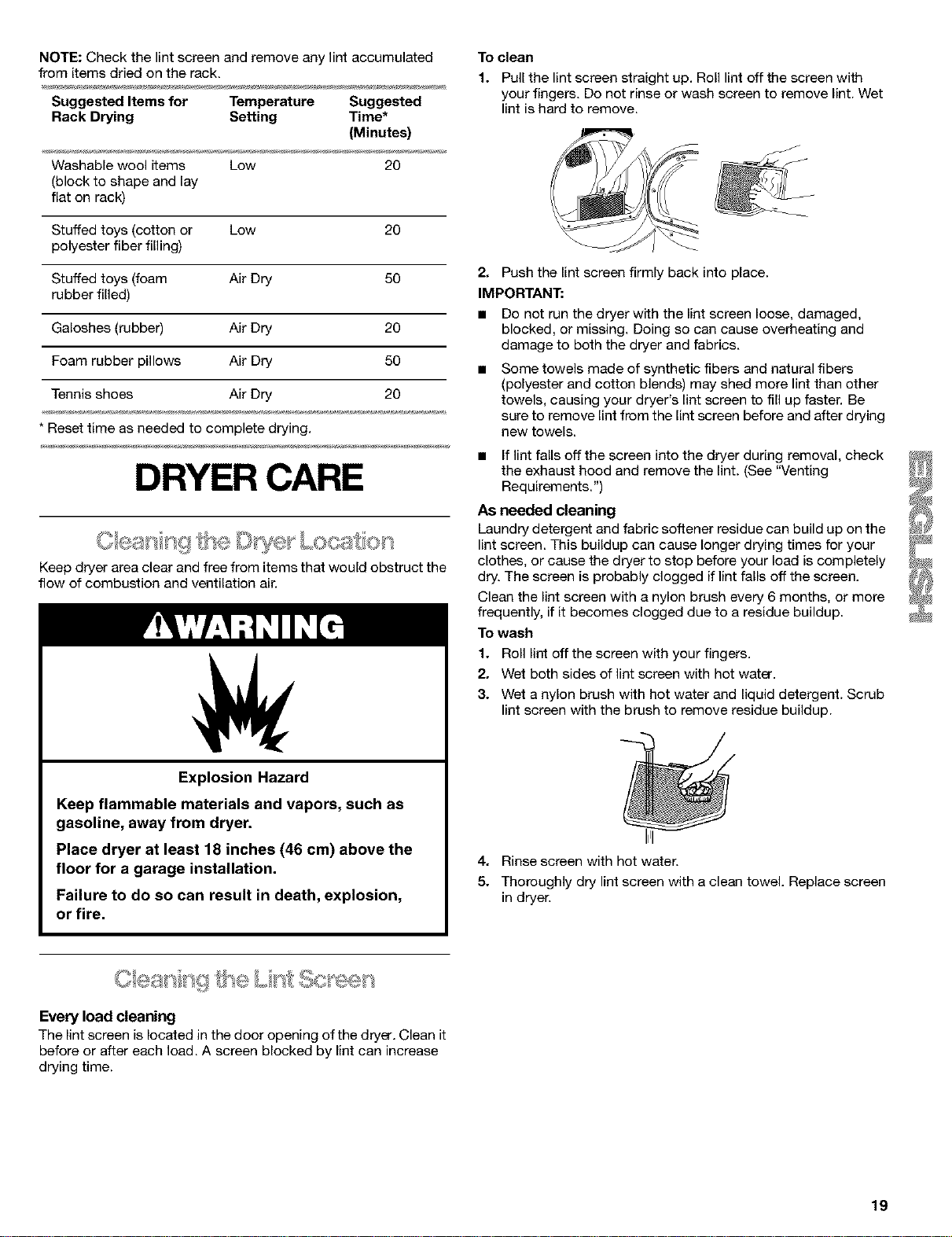
1. Open dryer door.
2. Place dryer rack over the bottom of the dryer door opening.
Rest the back wire on the dryer back ledge. Push down on
the frame front to secure over lint screen.
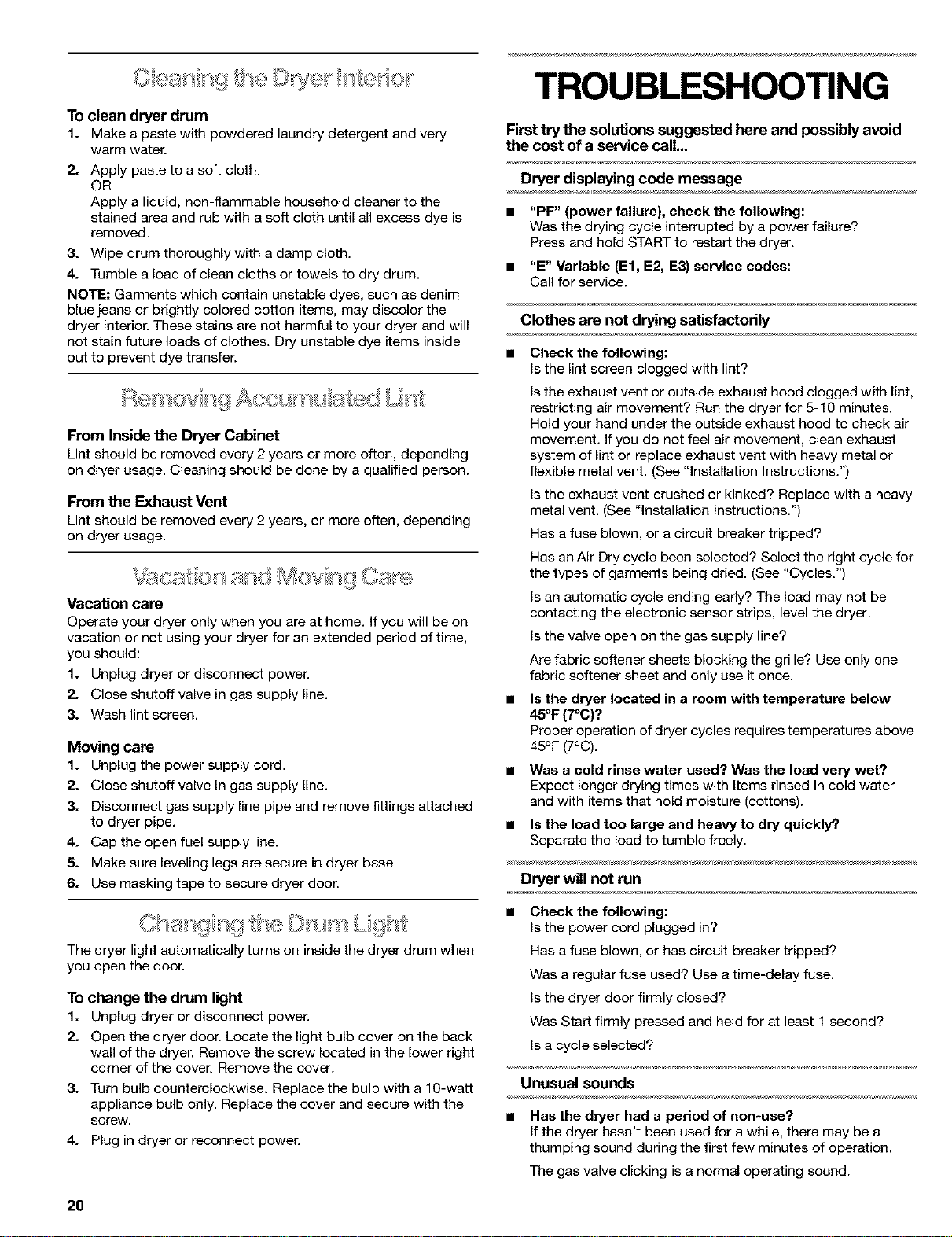
3. Place wet items on top of the rack. Allow space around items
for air to circulate. The rack does not move, but the drum will
rotate. Make sure items do not hang over the edges or
between rack grille.
4. CIosethe doon
5. Select TIMED DRY and MORE TIME or LESS TIME. Reset
time as needed to complete drying. Refer to the following
table.
6.
Select the desired temperature setting to match the fabrics in
your load by pressing TEMPB:b_,TURE. Items containing
foam, rubber, or plastic must be dried on a clothesline or by
using the Air Dry temperature setting. Refer to the following
table.
7. Start the dryen
To remove the dryer rack, lift it straight up and out of the dryer.
END of CYCLE SIQNAL
Press END of CYCLE SIGNAL to adjust the sound level or turn off
the signal.
18
NOTE: Check the lint screen and remove any lint accumulated
from items dried on the rack.
Suggested Items for Temperature Suggested
Rack Drying Setting Time*
(Minutes)
Washable wool items Low 20
(block to shape and lay
flat on rack)
Stuffed toys (cotton or Low 20
polyester fiber filling)
Stuffed toys (foam Air Dry 50
rubber filled)
Galoshes (rubber) Air Dry 20
Foam rubber pillows Air Dry 50
Tennis shoes Air Dry 20
* Reset time as needed to complete drying.
DRYER CARE
Keep dryer area clear and free from items that would obstruct the
flew of combustion and ventilation air.
Explosion Hazard
Keep flammable materials and vapors, such as
gasoline, away from dryer.
Place dryer at least 18 inches (46 cm) above the
floor for a garage installation.
Failure to do so can result in death, explosion,
or fire.
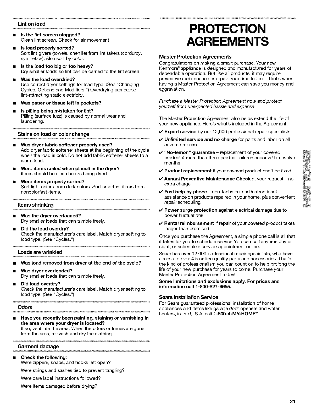
To clean
1. Pull the lint screen straight up. Roll lint off the screen with
your fingers. De net rinse or wash screen to remove lint. Wet
lint is hard to remove.
2. Push the lint screen firmly back into place.
IMPORTANT:
• Do not run the dryer with the lint screen loose, damaged,
blocked, or missing. Doing so can cause overheating and
damage to both the dryer and fabrics.
Some towels made of synthetic fibers and natural fibers
(polyester and cotton blends) may shed more lint than other
towels, causing your dryer's lint screen to fill up faster. Be
sure to remove lint from the lint screen before and after drying
new towels.
• If lint falls off the screen into the dryer during removal, check
the exhaust hood and remove the lint. (See "Venting
Requirements.")
As needed cleaning
Laundry detergent and fabric softener residue can build up on the
lint screen. This buildup can cause longer drying times for your
clothes, or cause the dryer to stop before your load is completely
dry. The screen is probably clogged if lint falls off the screen.
Clean the lint screen with a nylon brush every 6 months, or more
frequently, if it becomes clogged due to a residue buildup.
To wash
1. Roll lint off the screen with your fingers.
2. Wet both sides of lint screen with hot water.
3. Wet a nylon brush with hot water and liquid detergent. Scrub
lint screen with the brush to remove residue buildup.
I
4. Rinse screen with hot water.
5. Thoroughly dry lint screen with a clean towel. Replace screen
in dryer.
Every load cleaning
The lint screen is located in the door opening of the dryer. Clean it
before or after each load. A screen blocked by lint can increase
drying time.
19
TROUBLESHOOTING
To clean dryer drum
1. Make a paste with powdered laundry detergent and very
warm water.
2. Apply paste to a soft cloth.
OR
Apply a liquid, non-flammable household cleaner to the
stained area and rub with a soft cloth until all excess dye is
removed.
3. Wipe drum thoroughly with a damp cloth.
4. Tumble a load of clean cloths or towels to dry drum.
NOTE: Garments which contain unstable dyes, such as denim
blue jeans or brightly colored cotton items, may discolor the
dryer interior. These stains are not harmful to your dryer and will
not stain future loads of clothes. Dry unstable dye items inside
out to prevent dye transfer.
' " L, t
From Inside the Dryer Cabinet
Lint should be removed every 2 years or more often, depending
on dryer usage. Cleaning should be done by a qualified person.
From the Exhaust Vent
Lint should be removed every 2 years, or more often, depending
on dryer usage.
_ _@'i, _ ._ _,s,__ , _., _ . _= .
Vaca6on care
Operate your dryer only when you are at home. If you will be on
vacation or not using your dryer for an extended period of time,
you should:
1. Unplug dryer or disconnect power.
2. Close shutoff valve in gas supply line.
3. Wash lint screen.
Moving care
1. Unplug the power supply cord.
2. Close shutoff valve in gas supply line.
3. Disconnect gas supply line pipe and remove fittings attached
to dryer pipe.
4. Cap the open fuel supply line.
5. Make sure leveling legs are secure in dryer base.
6. Use masking tape to secure dryer door.
C{_SS_](;£!ISO_3@ [,]Yl. YYS ">"
'' .......... Lgll,
The dryer light automatically turns on inside the dryer drum when
you open the door.
To change the drum light
1. Unplug dryer or disconnect power.
2. Open the dryer door. Locate the light bulb cover on the back
wall of the dryer. Remove the screw located in the lower right
corner of the cover. Remove the cover.
3. Turn bulb counterclockwise. Replace the bulb with a 1g-watt
appliance bulb only. Replace the cover and secure with the
screw.
4. Plug in dryer or reconnect power.
Firsttry the solutions suggested here and possibly avoid
the cost of a service call...
Dryer displaying code message
• "PF" (power failure), check the following:
Was the drying cycle interrupted by a power failure?
Press and hold START to restart the dryer.
• "E" Variable (El, E2, E3) service codes:
Call for service.
Clothes are not drying satisfactorily
• Check the following:
Is the lint screen clogged with lint?
Is the exhaust vent or outside exhaust hood clogged with lint,
restricting air movement? Run the dryer for 5-10 minutes.
Hold your hand under the outside exhaust hood to check air
movement. If you do not feel air movement, clean exhaust
system of lint or replace exhaust vent with heavy metal or
flexible metal vent. (See "Installation Instructions.")
Is the exhaust vent crushed or kinked? Replace with a heavy
metal vent. (See "Installation Instructions.")
Has a fuse blown, or a circuit breaker tripped?
Has an Air Dry cycle been selected? Select the right cycle for
the types of garments being dried. (See "Cycles.")
Is an automatic cycle ending early? The load may not be
contacting the electronic sensor strips, level the dryer.
Is the valve open on the gas supply line?
Are fabric softener sheets blocking the grille? Use only one
fabric softener sheet and only use it once.
Is the dryer located in a room with temperature below
45OF(7oC)?
Proper operation of dryer cycles requires temperatures above
45°F (7°C).
Was a cold rinse water used? Was the load very wet?
Expect longer drying times with items rinsed in cold water
and with items that hold moisture (cottons).
Is the load too large and heavy to dry quickly?.
Separate the load to tumble freely.
Dryer will not run
• Check the following:
Is the power cord plugged in?
Has a fuse blown, or has circuit breaker tripped?
Was a regular fuse used? Use a time-delay fuse.
Is the dryer door firmly closed?
Was Start firmly pressed and held for at least 1 second?
Is a cycle selected?
Unusual sounds
• Has the dryer had a period of non-use?
If the dryer hasn't been used for a while, there may be a
thumping sound during the first few minutes of operation.
The gas valve clicking is a normal operating sound.
2O
Lint on load
• Is the lint screen clogged?
Clean lint screen. Check for air movement.
Is load properly sorted?
Sort lint givers (towels, chenille) from lint takers (corduroy,
synthetics). Also sort by color.
Is the load too big or too heavy?
Dry smaller loads so lint can be carried to the lint screen.
• Was the load overdried?
Use correct dryer settings for load type. (See "Changing
Cycles, Options and Modifiers.") Overdrying can cause
lint-attracting static electricity.
• Was paper or tissue left in pockets?
• Is pilling being mistaken for lint?
Pilling (surface fuzz) is caused by normal wear and
laundering.
Stains on load or color change
• Was dryer fabric softener properly used?
Add dryer fabric softener sheets at the beginning of the cycle
when the load is cold. Do not add fabric softener sheets to a
warm load.
• Were items soiled when placed in the dryer?
Items should be clean before being dried.
• Were items properly sorted?
Sort light colors from dark colors. Sort colorfast items from
noncolorfast items.
Items shrinking
• Was the dryer overloaded?
Dry smaller loads that can tumble freely.
• Did the load overdry?
Check the manufacturer's care label. Match dryer setting to
load type. (See "Cycles.")
Loads are wrinkled
• Was load removed from dryer at the end of the cycle?
• Was dryer overloaded?
Dry smaller loads that can tumble freely.
• Did load overdry?
Check the manufacturer's care label. Match dryer setting to
load type. (See "Cycles.")
Odors
Have you recently been painting, staining or varnishing in
the area where your dryer is located?
If so, ventilate the area. When the odors or fumes are gone
from the area, re-wash and dry the clothing.
Garment damage
• Check the following:
Were zippers, snaps, and hooks left open?
Were strings and sashes tied to prevent tangling?
Were care label instructions followed?
Were items damaged before drying?
PROTECTION
AGREEMENTS
Master Protection Agreements
Congratulations on making a smart purchase. Your new
Kenmore®appliance is designed and manufactured for years of
dependable operation. But like all products, it may require
preventive maintenance or repair from time to time. That's when
having a Master Protection Agreement can save you money and
aggravation.
Purchase a Master Protection Agreement now and protect
yourself from unexpected hassle and expense.
The Master Protection Agreement also helps extend the life of
your new appliance. Here's what's included in the Agreement:
v" Expert service by our 12,000 professional repair specialists
v" Unlimited service and no charge for parts and labor on all
covered repairs
v" "No-lemon" guarantee - replacement of your covered
product if more than three product failures occur within twelve
months
v" Product replacement if your covered product can't be fixed
v" Annual Preventive Maintenance Check at your request - no
extra charge
v" Fast help by phone - non-technical and instructional
assistance on products repaired in your home, plus convenient
repair scheduling
v" Power surge protection against electrical damage due to
power fluctuations
v" Rental reimbursement if repair of your covered product takes
longer than promised
Once you purchase the Agreement, a simple phone call is all that
it takes for you to schedule eervice.You can call anytime day or
night, or schedule a service appointment online.
Sears has over 12,000 professional repair specialists, who have
access to over 4.5 million quality parts and accessories. That's
the kind of professionalism you can count on to help prolong the
life of your new purchase for years to come. Purchase your
Master Protection Agreement today!
Some limitations and exclusions apply. For prices and
information call 1-800-827-6655.
Sears Installation Service
For Sears guaranteed professional installation of home
appliances and items like garage door openers and water
heaters, in the U.S.A. call f-800-4-MY-HOME ®.
21
Your Home
For repair-in your home-of all major brand appliances,
lawn and garden equipment, or heatingand cooling systems,
no matter who made it, no matter who sold it!
For the replacement parts, accessories and
owner's manuals that you need to do-it-yourself.
For Sears professional installationof home appliances
and items like garage door openers and water heaters.
1-800-4-MY-HOME ® (1-800-469-4e63)
Call anytime, day or night(U.S.A. and Canada)
www.sears.com www.sears.ca
Our Home
For repair of carry-initems likevacuums, lawn equipment,
and electronics, call or go on-linefor the locationof your nearest
Sears Parts & Repair Center.
1-800-488-1222
Call anytime, day or night (U.S.A. only)
www.sears.com
To purchase a protectionagreement (U.S.A.)
or maintenance agreement (Canada) on a product serviced by Sears:
1-800-827-6655 (U.S.A.) 1-800-361-6665 (Canada)
:ilililililililililililililili_
Para pedir servicio de reparaci6n
a domicilio, y para ordenar piezas:
1-888-SU-HOGAR _
(1-888-784-6427)
Au Canada pour service en fran_ais:
1-800-LE-FOYER Mc
(1-800-533-6937)
www.sears.ca
SEARS
8519320A . TM SM . 9/02
® RegisteredTrademark / Trademark/ Service Mark of Sears, Roebuckand Co. PrintedinU.S.A.
© Sears, Roebuckand Co. . TM . SM " " Impreso en EE. UU.
® Marca Reglstrada/ Marca de Comerclo/ Marca de Servlclo deSears, Roebuck and Co.