User Manual
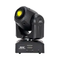
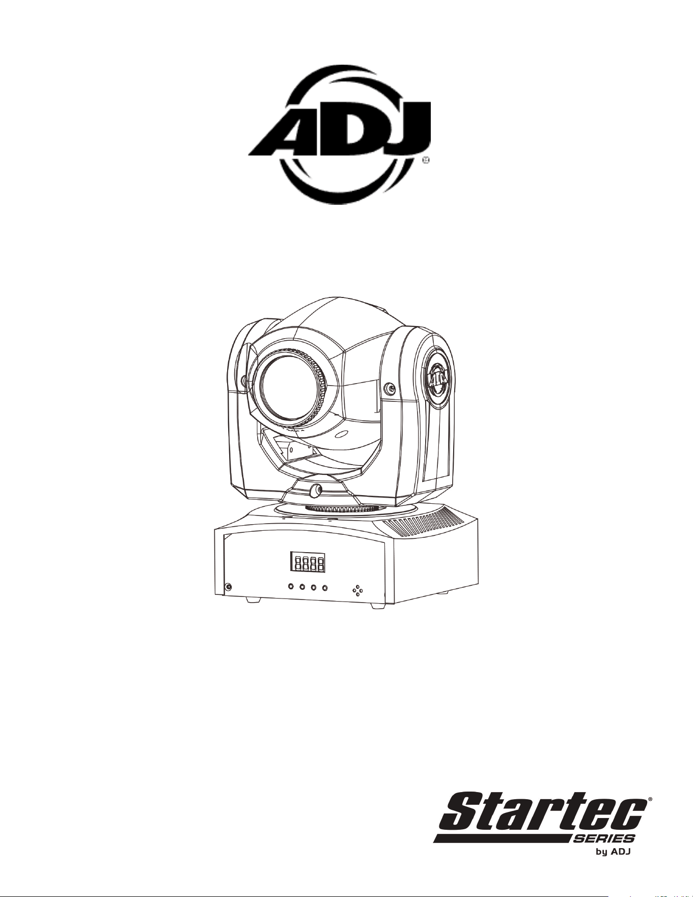
STINGER SPOT

©2020 ADJ Products, LLC all rights reserved. Information, specications, diagrams, images, and
instructions herein are subject to change without notice. ADJ Products, LLC logo and identifying
product names and numbers herein are trademarks of ADJ Products, LLC. Copyright protection
claimed includes all forms and matters of copyrightable materials and information now allowed by
statutory or judicial law or hereinafter granted. Product names used in this document may be trade-
marks or registered trademarks of their respective companies and are hereby acknowledged. All
non-ADJ Products, LLC brands and product names are trademarks or registered trademarks of their
respective companies.
ADJ Products, LLC and all aliated companies hereby disclaim any and all liabilities for property,
equipment, building, and electrical damages, injuries to any persons, and direct or indirect economic
loss associated with the use or reliance of any information contained within this document, and/or as
a result of the improper, unsafe, unsucient and negligent assembly, installation, rigging, and opera-
tion of this product.
Europe Energy Saving Notice
Energy Saving Matters (EuP 2009/125/EC)
Saving electric energy is a key to help protecting the enviroment. Please turn o all electrical products when
they are not in use. To avoid power consumption in idle mode, disconnect all electrical equipment from power
when not in use. Thank you!
ADJ Products, LLC - www.adj.com - Stinger Spot User Manual Page 2

ADJ Products, LLC - www.adj.com - Stinger Spot User Manual Page 3
Unpacking: Thank you for purchasing the Stinger Spot by ADJ Products, LLC. Every Stinger Spot
has been thoroughly tested and has been shipped in perfect operating condition. Carefully check the
shipping carton for damage that may have occurred during shipping. If the carton appears to be dam-
aged, carefully inspect your xture for any damage and be sure all equipment necessary to operate the
unit has arrived intact. In the event damage has been found or parts are missing, please contact our
toll-free customer support number for further instructions. Please do not return this unit to your dealer
without contacting customer support rst.
Introduction: The Stinger Spot is a DMX intelligent, moving head, mini LED xture. The Stinger Spot
can operate as a stand alone xture or in a primary/secondary conguration. The Stinger Spot has
three operating modes: sound active mode, show mode, and DMX controlled. This xture is suitable
for theaters, studios, retail stores, and other similar locations. For best results use fog or special eects
smoke to enhance the beam’s projections.
Customer Support: ADJ Products, LLC provides a toll free customer support line, to provide help and
to answer any question should you encounter problems during your set up or initial operation. You
may also visit us on the web at www.adj.com for any comments or suggestions. Service Hours are
Monday through Friday 8:00 a.m. to 4:30 p.m. Pacic Standard Time.
Voice: (800) 322-6337
Fax: (323) 582-2941
E-mail: [email protected]
To purchase parts online, visit parts.adj.com.
Warning! To prevent or reduce the risk of electrical shock or re, do not expose this unit to rain or
moisture.
Warning! This may cause severe eye damage. Avoid looking directly into the light source at all times!
Stinger Spot General Information

Stinger Spot General Instructions
To optimize the performance of this product, please read these operating instructions carefully to
familiarize yourself with the basic operations of this unit. These instructions contain important safety
information regarding the use and maintenance of this unit. Please keep this manual with the unit, for
future reference.
Stinger Spot Warranty Registration
The Stinger Spot carries a 1 year (365 days) limited warranty. Please fill out the enclosed warranty
card to validate your purchase and warranty. You may also register your product online at www.adj.
com. All returned service items whether under warranty or not, must be freight pre-paid and accom-
pany a return authorization (R.A.) number. If the unit is under warranty you must provide a copy of
your proof of purchase invoice. Please contact ADJ Products, LLC customer support for a R.A. num-
ber
ADJ Products, LLC - www.adj.com - Stinger Spot User Manual Page 4
Stinger Spot Features
• DMX-512 Protocol Compatible (9 or 11 DMX Channels)
• 7 Colors + White
• Fixed Gobo Wheel with 7 Gobos + Spot
• 3 Operating Modes - Sound Active, Show Mode, & DMX Control
• Internal Microphone
• Digital Display for Address and Function Setting
• 4 Preprogrammed Shows
Stinger Spot Handling Precautions
Caution! There are no user serviceable parts inside this unit. Do not attempt any repairs yourself,
doing so will void your manufacturer’s warranty. In the unlikely event your unit may require service
please contact ADJ Products, LLC.
During operating the housing may become extremely hot. Avoid touching the unit with bare hands
while in use.
ADJ Products, LLC will not accept any liability for any resulting damages caused by the non-obser-
vance of this manual or any unauthorized modification to this unit.

ADJ Products, LLC - www.adj.com - Stinger Spot User Manual Page 5
Stinger Spot Safety Precautions
For Your Own Personal Safety, Please Read and Understand This Manual Completely Before
You Attempt To Install Or Operate This Unit!
• To reduce the risk of electrical shock or fire, do not expose this unit to rain or moisture.
• Do not spill water or other liquids into or onto your unit.
• Be sure that the local power outlet matches the required voltage of your unit.
• Do not attempt to operate this unit if the power cord has been frayed or broken.
• Do not attempt to remove or break off the ground prong from the electrical cord. This prong is
used to reduce the risk of electrical shock and fire in case of an internal short.
• Disconnect from main power before making any type of connection.
• Do not remove the cover under any conditions. There are no user serviceable parts inside.
• Never operate this unit when its cover is removed.
• Always be sure to mount this unit in an area that will allow proper ventilation. Allow about 6”
(15cm) between this device and a wall.
• Do not attempt to operate this unit if it has been damaged.
• This unit is intended for indoor use only, use of this product outdoors voids all warranties.
• Always mount this unit in safe and stable matter.
• Power-supply cords should be routed so that they are not likely to be walked on or pinched by
items placed upon or against them, paying particular attention to cords at plugs, convenience
receptacles, and the point where they exit from the appliance.
• Cleaning -The fixture should be cleaned only as recommended by the manufacturer.
• Heat -This fixture should be situated away from heat sources such as radiators, heat registers,
stoves, or other appliances (including amplifiers) that produce heat.
• The fixture should be serviced by qualified service personnel when:
A. Objects have fallen, or liquid has been spilled into the applicance.
B. The applicance has been exposed to rain or water.
C. The applicance does not appear to operate normally or exhibits a marked change in perfor-
mance.
ADJ Products, LLC - www.adj.com - Stinger Spot User Manual Page 6
When installing the unit, the trussing or area of installation must be able to hold 10 times the weight
without any deformation. When installing the unit must be secured with a secondary safety attach-
ment, e.g. and appropriate safety cable. Never stand directly below the unit when mounting, remov-
ing, or servicing the unit.
Overhead mounting requires extensive experience, including calculating working load limits, installa-
tion material being used, and perodic safety inspection of all installation material and unit. If you lack
these qualifications, do not attempt the installation yourself.
The installaiton should be checked by a skilled person once a year.
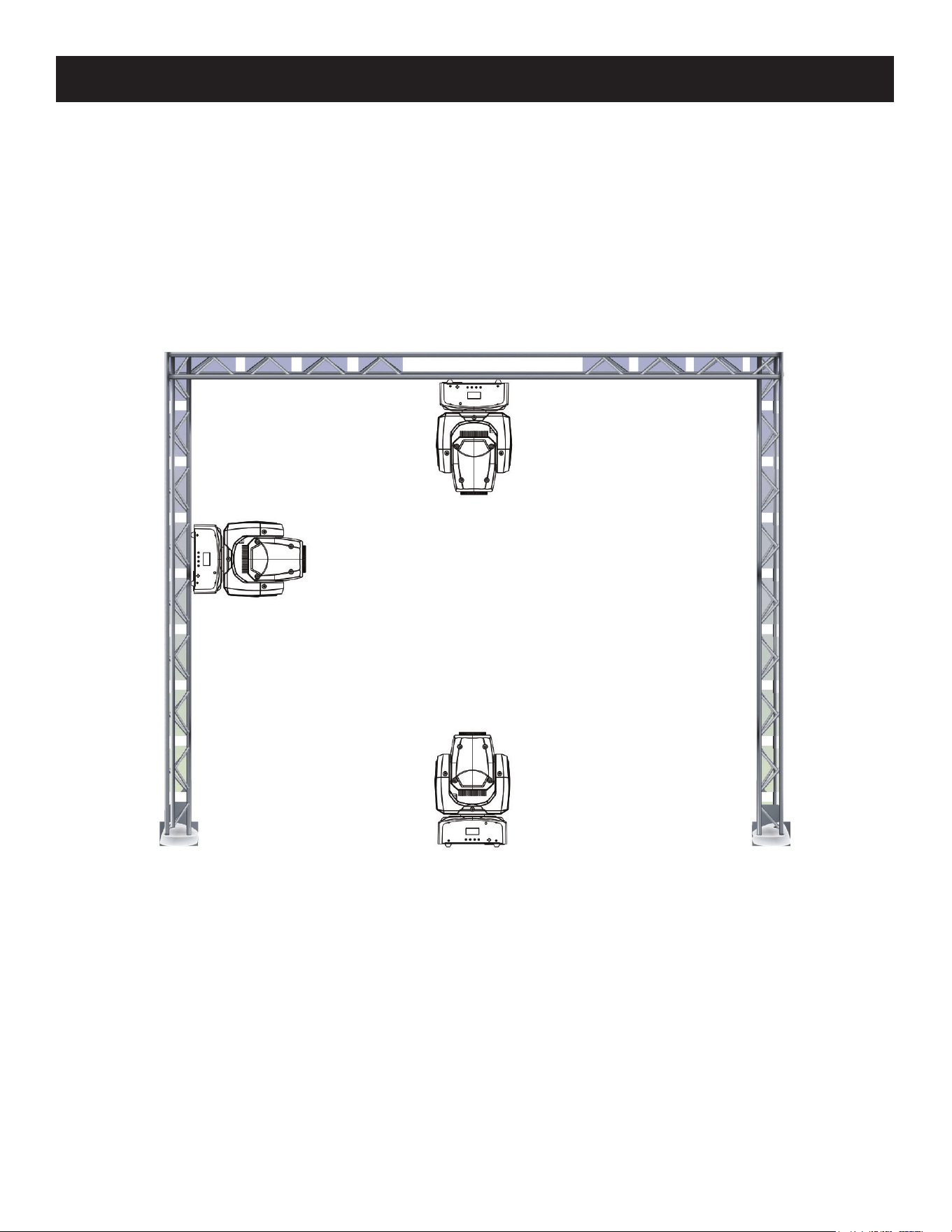
Stinger Spot Mounting
The Stinger Spot is fully operational in three different mounting positions: hanging upside-down from
a trussing setup, sideways from a trussing setup, or set on a flat level surface.
Be sure this fixture is kept at least 3.3 feet (0.5m) away from any flammable materials, such as deco-
rations. Always use an install an appropriately rated safety cable to prevent accidental damage and/
or injury in the event the clamp fails.
ADJ Products, LLC - www.adj.com - Stinger Spot User Manual Page 7
NOTICE: The suitable environmental temperature range for this lighting fixture is -13 deg F to 113
deg F (-25 deg C to 45 deg C). Do not place this lighting fixture in an environment where the tem-
peratures fall outside of this range. This will allow the fixture to run at its best and help prolong the
life of the fixture.
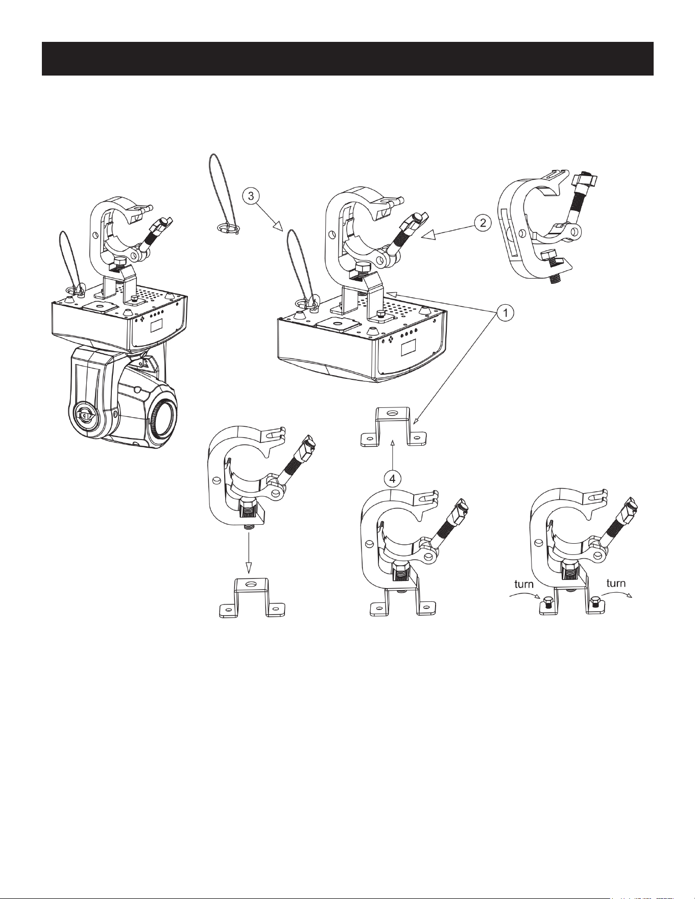
Stinger Spot Mounting
Screw one clamp via a M12 screw and nut to the included bracket. Attach the bracket to the bottom
of the Stinger Spot using the included screws. Attach the eyehole screw to the bottom of the base
and pull the safety-cable through the screw and over the trussing system or a safe fixation spot.
Insert the end in the carabine and tighten the safety screw.
ADJ Products, LLC - www.adj.com - Stinger Spot User Manual Page 8
Stinger Spot DMX Set Up
Power Supply: The ADJ Stinger Spot contains an automatic voltage switch, which will auto sense
the voltage when it is plugged into the power source. With this switch there is no need to worry
about the correct power voltage, this unit can be plugged in anywhere.
DMX-512: DMX is short for Digital Multiplex. This is a universal pro-tocol used by most lighting and
controller manufactures as a form of communication between intelligent fixtures and controllers. A
DMX controller sends DMX data instructions from the controller to the fixture. DMX data is sent as
serial data that travels from fixture to fixture via the DATA “IN” and DATA “OUT” XLR terminals locat-
ed on all DMX fixtures (most controllers only have a DATA “OUT” terminal).
DMX Linking: DMX is a language allowing all makes and models of different manufacurers to be
linked together and operate from a single controller, as long as all fixtures and the controller are DMX
compliant. To ensure proper DMX data transmission, when using several DMX fixtures try to use
the shortest cable path possible. The order in which fixtures are connected in a DMX line does not
influence the DMX addressing. For example; a fixture assigned a DMX address of 1 may be placed
anywhere in a DMX line, at the beginning, at the end, or anywhere in the middle. Therefore, the first
fixture controlled by the controller could be the last fixture in the chain. When a fixture is assigned
a DMX address of 1, the DMX controller knows to send DATA assigned to address 1 to that unit, no
matter where it is located in the DMX chain.
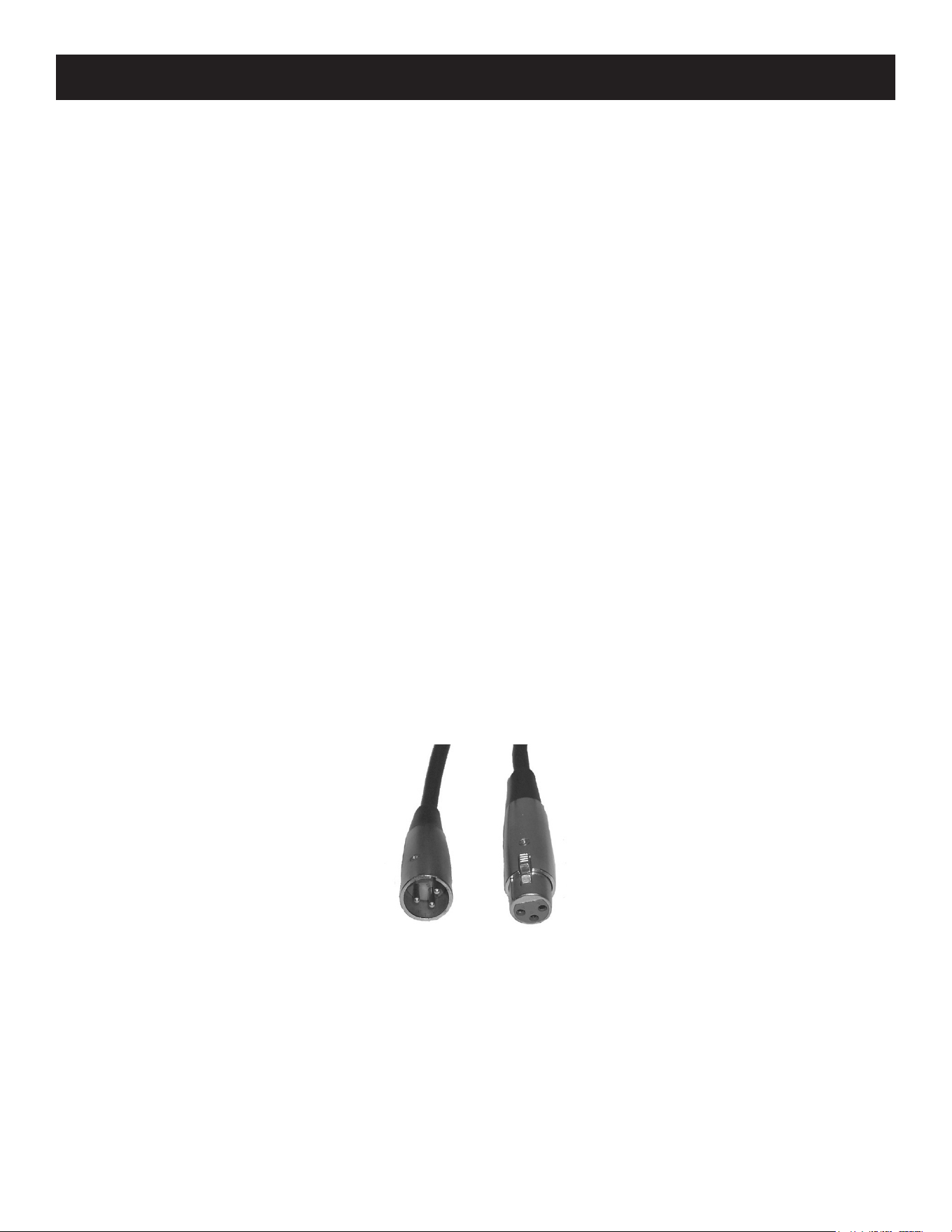
Data Cable (DMX Cable) Requirements (For DMX and Primary/Secondary Operation): The
Stinger Spot can be controlled via DMX-512 protocol. The Stinger Spot two DMX channel modes;
9 channel mode & 11 channel mode. The DMX address is set electronically using the controls on
the front panel of the unit. Your unit and your DMX controller require a approved DMX-512 110 Ohm
Data cable for data input and data output (Figure 1). We recommend Accu-Cable DMX cables. If you
are making your own cables, be sure to use standard 110-120 Ohm shielded cable. This cable may
be purchased at almost all professional sound and lighting stores.
Figure 1
Your cables should be made with a male and female XLR connector on either end of the cable. Also
remember that DMX cable must be daisy chained and cannot be split.
ADJ Products, LLC - www.adj.com - Stinger Spot User Manual Page 9
Stinger Spot DMX Set Up
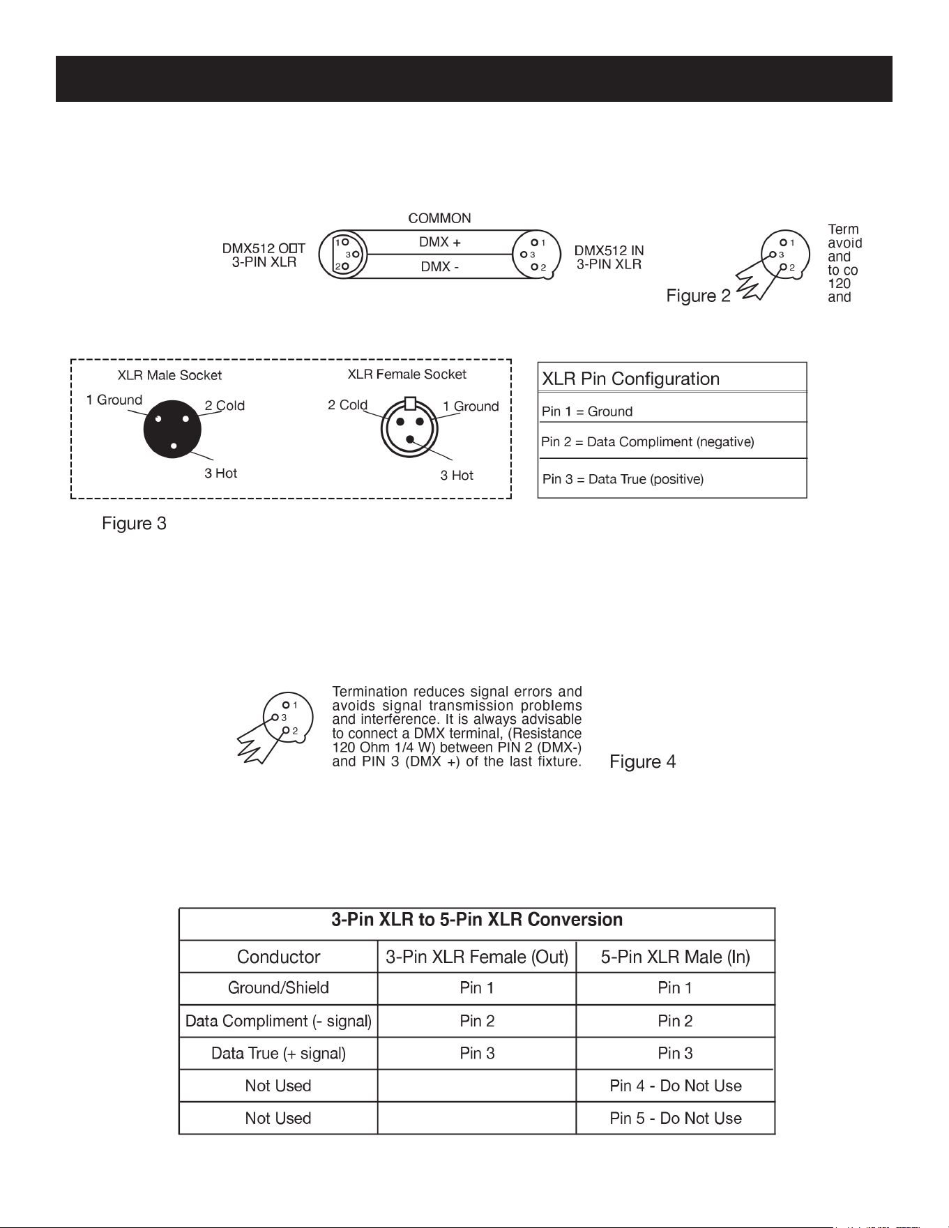
Notice: Be sure to follow figures two and three when making your own cables. Do not use the
ground lug on the XLR connector. Do not connect the cable’s shield conductor to the ground lug
or allow the shield conductor to come in contact with the XLR’s outer casing. Grounding the shield
could cause a short circuit and erratic behavior.
Special Note: Line Termination. When longer runs of cable are used, you may need to use a ter-
minator on the last unit to avoid erratic behavior. A terminator is a 110-120 ohm 1/4 watt resistor
which is connected between pins 2 and 3 of a male XLR connector (DATA + and DATA -). This unit is
inserted in the female XLR connector of the last unit in your daisy chain to terminate the line. Using a
cable terminator (ADJ part number Z-DMX/T) will decrease the possibilities of erratic behavior.
5-Pin XLR DMX Connectors. Some manufacturers use 5-pin DMX-512 data cables for DATA trans-
mission in place of 3-pin. 5-pin DMX fixtures may be implemented in a 3-pin DMX line. When insert-
ing standard 5-pin data cables in to a 3-pin line, a cable adaptor must be used. These adaptors are
readily available at most electronics stores. The chart below details a proper cable conversion.
ADJ Products, LLC - www.adj.com - Stinger Spot User Manual Page 10
Stinger Spot System Menu
Primary Mode

ADJ Products, LLC - www.adj.com - Stinger Spot User Manual Page 11
System Menu: When making adjustments press ENTER to conrm your setup then press and
hold the MENU button for at least 3 seconds. To exit without making any adjustments press
the MENU button. The display will lock after 30 seconds, press the MENU button for 3 seconds
to unlock.
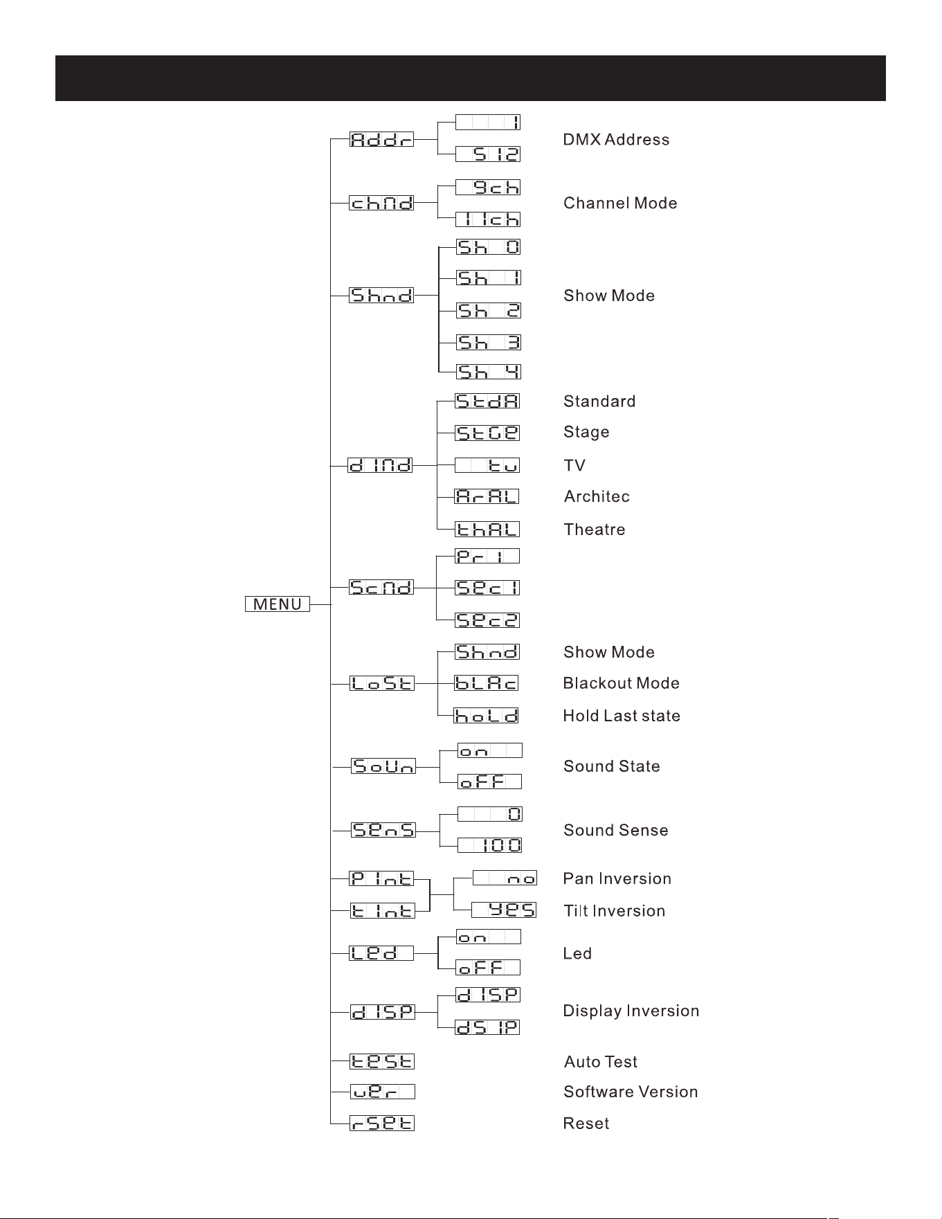
ADDR - DMX Address Setting.
1. Press the either the MENU, UP, or DOWN buttons until “ADDR” is displayed, press ENTER.
2. The current address will now be displayed and ashing. Press the UP or DOWN buttons to nd
your desired address. Press ENTER to set your desired DMX address.
CHND - This will let select your desired DMX channel mode.
1. Press the either the MENU button until “CHND” is displayed, press ENTER. Either “9CH” or
“11CH” will be displayed.
2. Press the UP or DOWN buttons to nd your desired DMX channel mode and press ENTER to
conrm and exit.
SHND - Show modes 0-4 (Factory programs). Show mode can run with or without sound active
mode active.
1. Press the MENU button until “SHND” is displayed, press ENTER.
2. “Sh X” will now be displayed, “X” representing a number between 0-4. Shows 1-4 are factory
programs, while show “0” is random mode.
3. When you have found your desired show press ENTER, then press and hold the MENU button for
at least 3 seconds to activate. After you have set your desired show, it can be changed at any
time using the UP or DOWN buttons.
DIND - This will let select your desired dimmer curve.
1. Press the either the MENU button until “DIND” is displayed, press ENTER. 1 of 5 dimmer curves
will be displayed. “STDA” (standard), “STGE” (stage), “TV” (TV), “ARAL” (theatrical), or “THAL”
(Architectural).
2. Press the UP and DOWN buttons to nd your desired dimmer curve and press ENTER to conrm
and exit.
SCND - This will let you set unit as the primary or secondary device in a primary/secondary
conguration.
1. Press the MENU button until “SCND” is displayed, press ENTER. Either “PRI”, “SEC1”, or “SEC2”
will be displayed.
2. Press the UP or DOWN buttons until your desired setting is displayed, press ENTER to conrm.
NOTE: In a primary/secondary conguration, you can set one xture to “PRI” and then set the next
xture to “SEC2”, the xtures will now have contrasting movements to each other.
Stinger Spot System Menu

ADJ Products, LLC - www.adj.com - Stinger Spot User Manual Page 12
Stinger Spot System Menu
LOST - In the event that the DMX signal is lost, interrupted, or power is lost, this mode denes
how the xture will behave until power or communication is re-established.
1. Press the MENU button until “LOST” is displayed, and either “HOLD”, “SHND”, or “BLAC” will be
displayed beneath.
2. Press ENTER and the bottom choice will begin to ash. Use the UP or DOWN buttons to choose
an operating mode you would like the unit to start up in when power is applied or the DMX signal
is lost.
• Hold - If the DMX signal is lost, the xture will stay in the last DMX setting. When power is ap-
plied, the unit will automatically default to the last DMX set up before power was disconnected.
• SHND (Show Mode) - If the DMX signal is lost or interrupted, the unit will automatically go into
show mode.
• BLAC (Blackout) - If the DMX signal is lost or interrupted, the unit will automatically go into stand-
by mode.
3. Press ENTER to conrm your desired setup.
SOUN - Sound Active mode.
1. Press the MENU button until “SOUN” is displayed, press ENTER.
2. The display will show either “ON” or “OFF”. Press the UP or DOWN buttons to select “ON” to
activate sound active mode, or “OFF” to deactivate sound active mode.
3. Press ENTER to conrm.
SENS - In this mode you can adjust the sound sensitivity.
1. Press the MENU button until “SENS” is displayed, press ENTER.
2. A number between 0-100 will be displayed. Press the UP or DOWN buttons to adjust the sound
sensitivity. 0 being the least sensitive, and 100 being the most sensitive.
3. When you have found your desired setting press ENTER to conrm.
PINT - Pan Inversion
1. Press the MENU button until “PINT” is displayed, press ENTER. Either “Yes” or “No” will be
displayed.
2. To activate the Pan inversion press the UP or DOWN buttons until “Yes” is displayed, and press
ENTER to conrm. To deactivate Pan inversion, select “No” and press ENTER.
TINT - Tilt Inversion
1. Press the MENU button until “TINT” is displayed, press ENTER. Either “Yes” or “No” will be
displayed.
2. To activate the tilt inversion press the UP or DOWN buttons until “Yes” is displayed, and press
ENTER to conrm. To deactivate tilt inversion, select “No” and press ENTER.
LED - With this function you can have the LED display turn o after 10 seconds.
1. Press the MENU button until “LED” is displayed, and press ENTER.
2. The display will show either “ON” or “OFF”. Press the UP or DOWN buttons to select “ON” to
keep the LED display on at all time, or “OFF” to set the LED display to switch o after 10
seconds.
3. Press ENTER to conrm.

DISP - This function will reverse the display 180 degrees.
1. Press the MENU button until “DISP” is displayed, and press ENTER.
2. Press UP or DOWN to ip the display between regular (“DISP”) and inverted (“DSIP”). Press EN-
TER to conrm your selection.
TEST - This function will run a self-test program.
1. Press the MENU button until “TEST” is displayed, and press ENTER.
2. The xture will now run a self-test.
VER - Use this function to display the software version of the unit.
1. Press the MENU button until “VER” is displayed, and press ENTER.
2. The display will show the software version.
RSET - Use this function to reset the unit.
1. Press the MENU button until “RSET” is displayed, and press ENTER.
2. The xture will now reset to default factory settings.
ADJ Products, LLC - www.adj.com - Stinger Spot User Manual Page 13
Stinger Spot System Menu
ADJ Products, LLC - www.adj.com - Stinger Spot User Manual Page 14
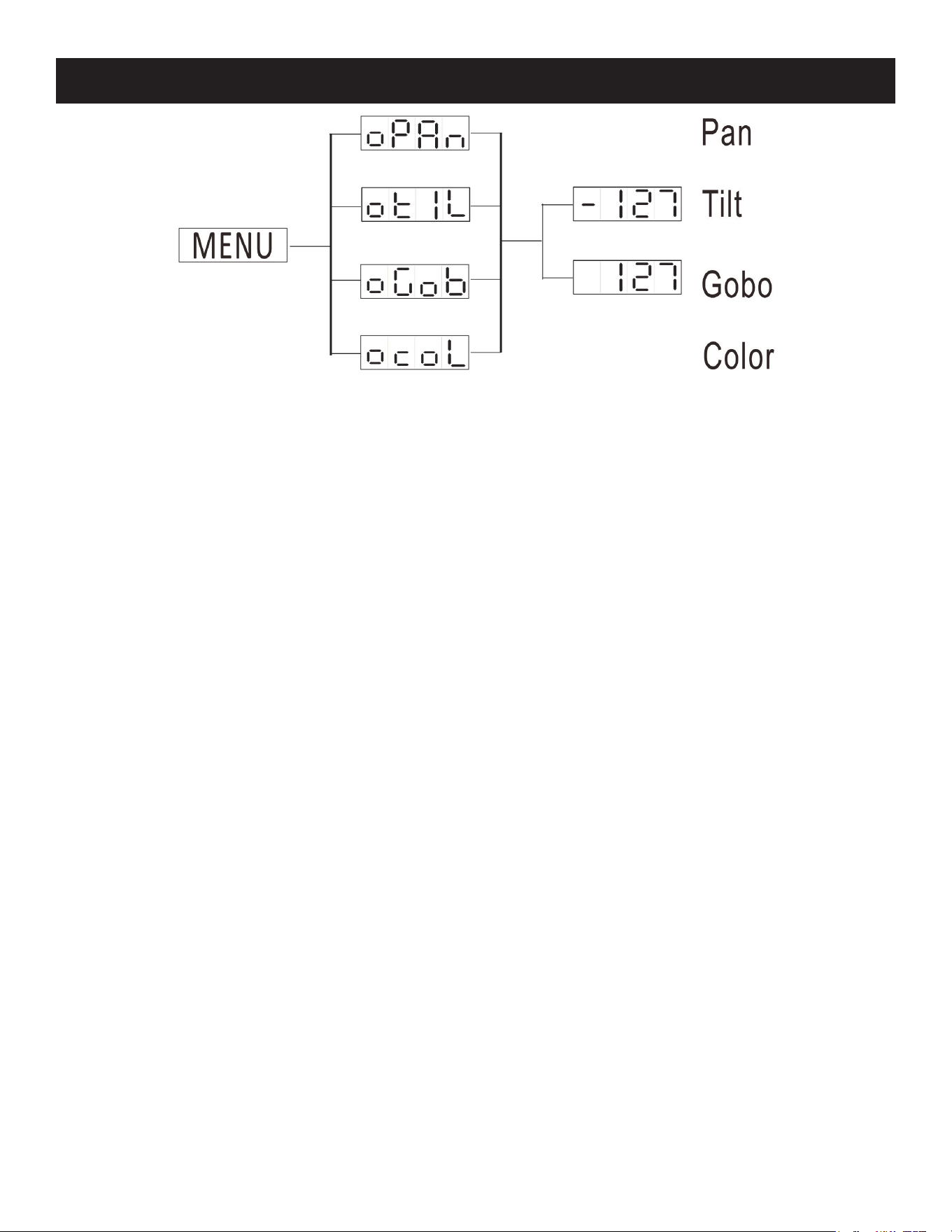
Stinger Spot Home Adjustment Menu
To enter the home position adjustment menu, press the ENTER button for at least 5 seconds. In this
submenu you are able to adjust the original position of the pan position, tilt position, color wheel
position, and gobo wheel position.
OPAN - Adjustment of the pan position.
1. Press the ENTER button for at least 5 seconds, then press the UP or DOWN buttons so that
“OPAN” is displayed. Press ENTER.
2. Use the UP and DOWN buttons to make your adjustments, and then press ENTER to conrm.
Press the MENU button for one second to exit.
OTIL - Adjustment of the tilt position.
1. Press the ENTER button for atl east 5 seconds, then press the UP or DOWN buttons so that
“OTIL” is displayed. Press ENTER.
2. Use the UP and DOWN buttons to make your adjustments, and then press ENTER to conrm.
Press the MENU button for one second to exit.
OGOB - Adjustment of the gobo wheel.
1. Press the ENTER button for at least 5 seconds, then press the UP or DOWN buttons so that
“OGOB” is displayed. Press ENTER.
2. Use the UP and DOWN buttons to make your adjustments, and then press ENTER to conrm.
Press the MENU button for one second to exit.
OCOL - Adjustment for the color wheel.
1. Press the ENTER button for at least 5 seconds, then press the UP or DOWN buttons so that
“OCOL” is displayed. Press ENTER.
2. Use the UP and DOWN buttons to make your adjustments, and then press ENTER to conrm.
Press the MENU button for one second to exit.

ADJ Products, LLC - www.adj.com - Stinger Spot User Manual Page 15
Stinger Spot Operation
Universal DMX Control: This function allows you to use a universal DMX-512 controller to
control the chases and patterns, dimmer and strobe. A DMX controller allows you to create
unique programs tailored to your individual needs.
1. The Stinger Spot has 2 DMX channel modes; 9 channel mode or 11 channel mode. See 9-Chan-
nel Mode and 11-Channel Mode section for details.
2. To control your xture in DMX mode, follow the procedures in the DMX Set Up section as well as
the set-up specications that are included with your DMX controller.
3. Use the controller’s faders to control the various DMX xture traits.
4. This will allow you to create your own programs.
5. Follow the instructions in the DMX Set Up section to set the DMX address.
6. For longer cable runs (more than a 100 feet) use a terminator on the last xture.
7. For help operating in DMX mode consult the manual included with your DMX controller.
Sound Active Mode: This mode allows either a single unit or a set of several units that have
been linked together to run to the beat of the music.
1. Press the MENU button until “SOUN” is displayed, and press ENTER. Press the UP or DOWN
buttons so that “ON” is displayed and press ENTER.
2. Press the MENU button until “SENS” is displayed, and press ENTER. Use the UP and DOWN
buttons to adjust the sound sensitivity. Press ENTER when you have found your desired sensitiv-
ity level.
Show Mode: This mode allows either a single unit or several unit that have been linked togeth-
er to run one of four shows that can be selected by the user.
1. Press the MENU button until “SHND” is displayed, and press ENTER.
2. Press the UP or DOWN buttons until you nd your desired show, and press ENTER.

Stinger Spot Primary-Secondary Set Up
Primary-Secondary Operation: This function will allow you to link up to 16 units together and oper-
ate without a controller. The units will be sound activated. In Primary-Secondary operation one unit
will act as the controlling unit and the others will react to the controlling units programs. Any unit can
act as a Primary or as a Secondary.
1. Using approved DMX data cables, daisy chain your units together via the XLR connector on the
rear of each unit. Remember the male XLR connector is the input and the female XLR connec-
tor is the output. The rst unit in the chain (primary) will use the female XLR connector only, and
the last unit in the chain will use the male XLR connector only. For longer cable runs, the use of a
terminator on the last xture is strongly recommended.
2. On the primary unit, press the MENU button until “SCND” is displayed, and press ENTER. Use
the UP and DOWN buttons to scroll to the “PRI” setting and press ENTER.
3. After setting the primary unit to the primary setting, congure the primary unit to the desired op-
erating mode.
4. On the secondary units, press the MENU button until “SCND” is displayed, and press ENTER.
Choose either “Sec1” or “Sec2” and press ENTER. See the System Menu section for more infor-
mation.
5. The secondary units will now follow the primary unit.
ADJ Products, LLC - www.adj.com - Stinger Spot User Manual Page 16
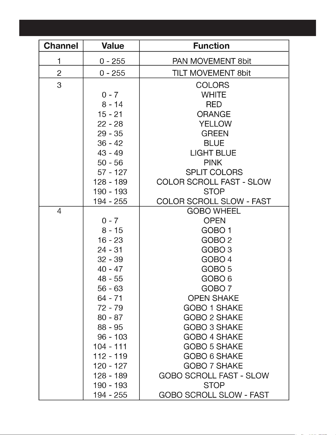
Stinger Spot 9-Channel Mode
ADJ Products, LLC - www.adj.com - Stinger Spot User Manual Page 17
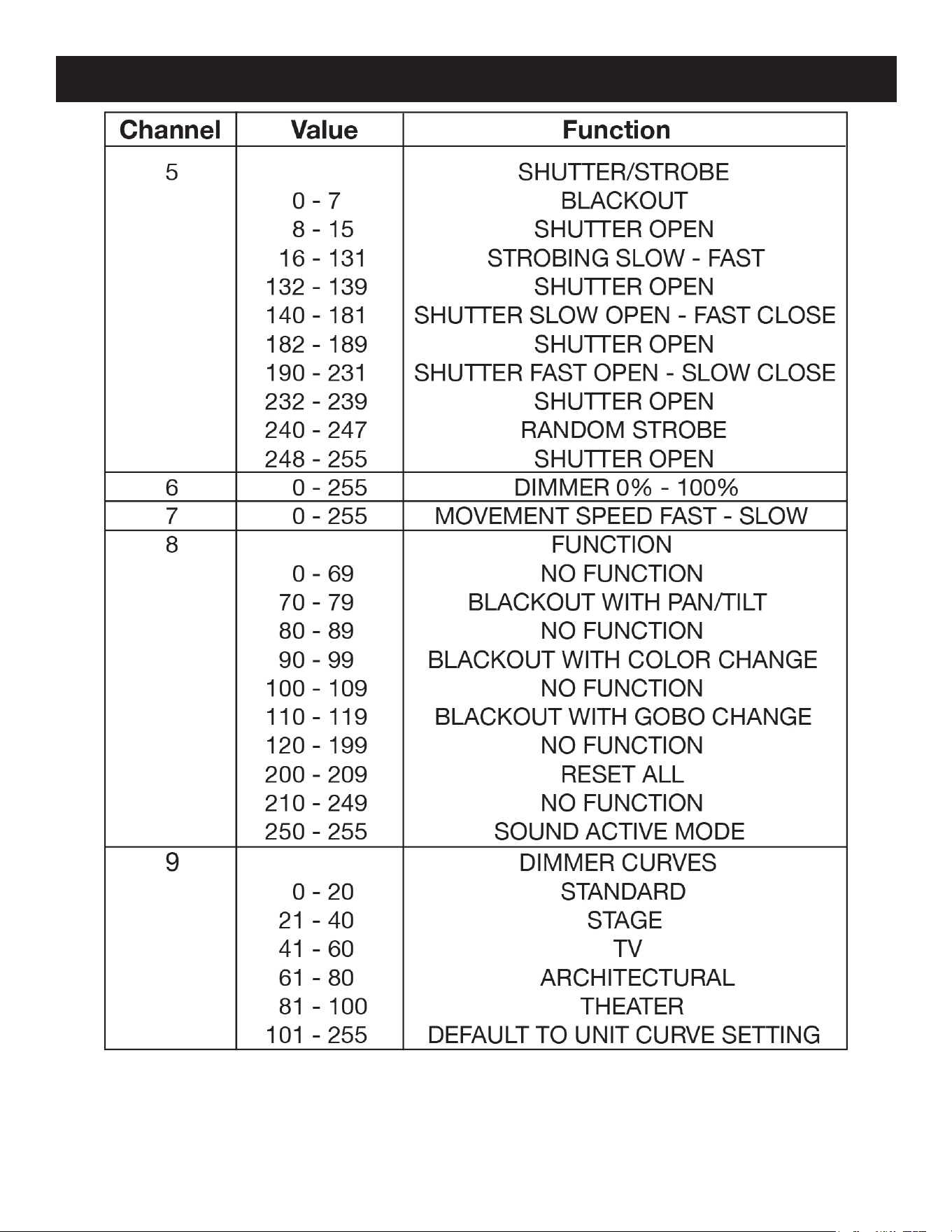
Stinger Spot 9-Channel Mode
ADJ Products, LLC - www.adj.com - Stinger Spot User Manual Page 18
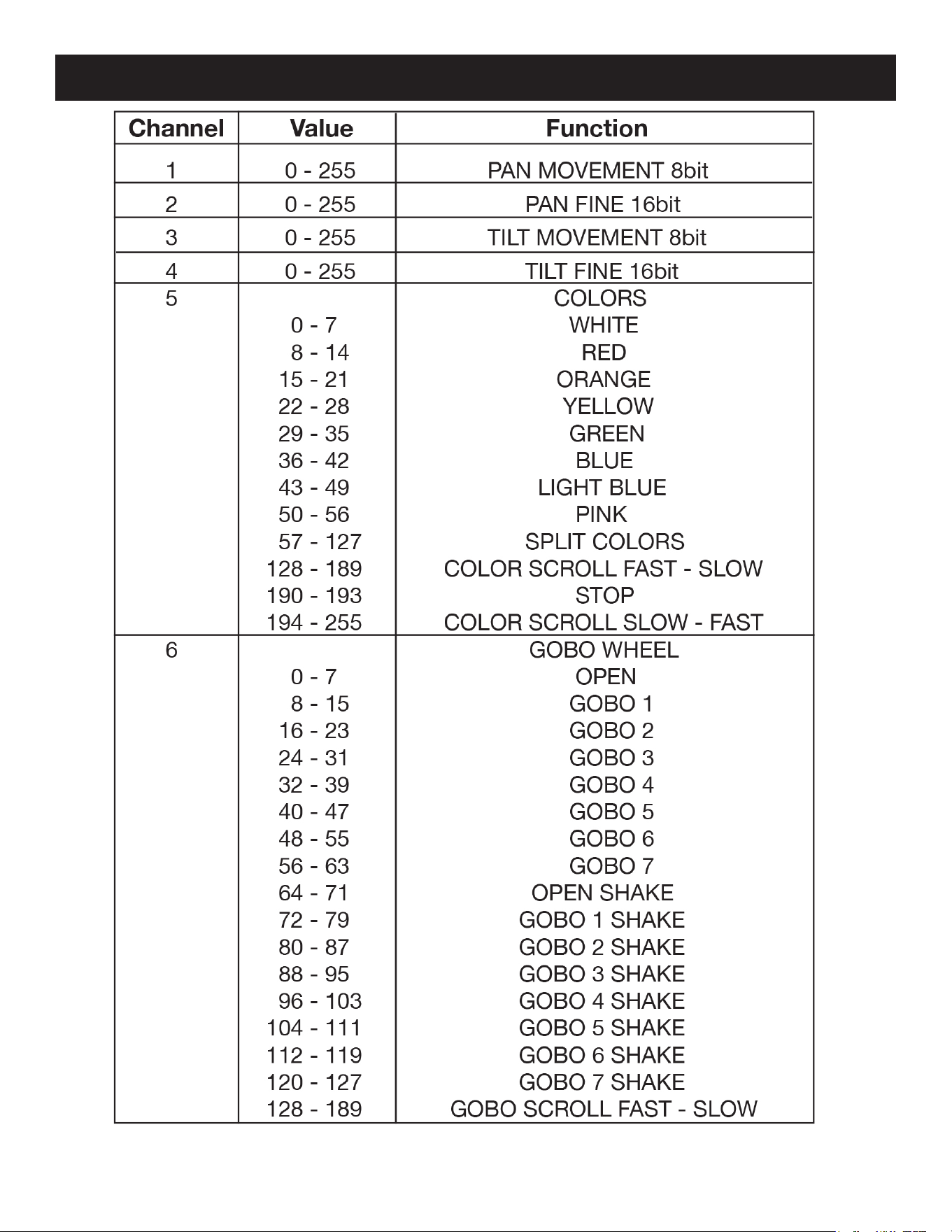
Stinger Spot 11-Channel Mode
ADJ Products, LLC - www.adj.com - Stinger Spot User Manual Page 19
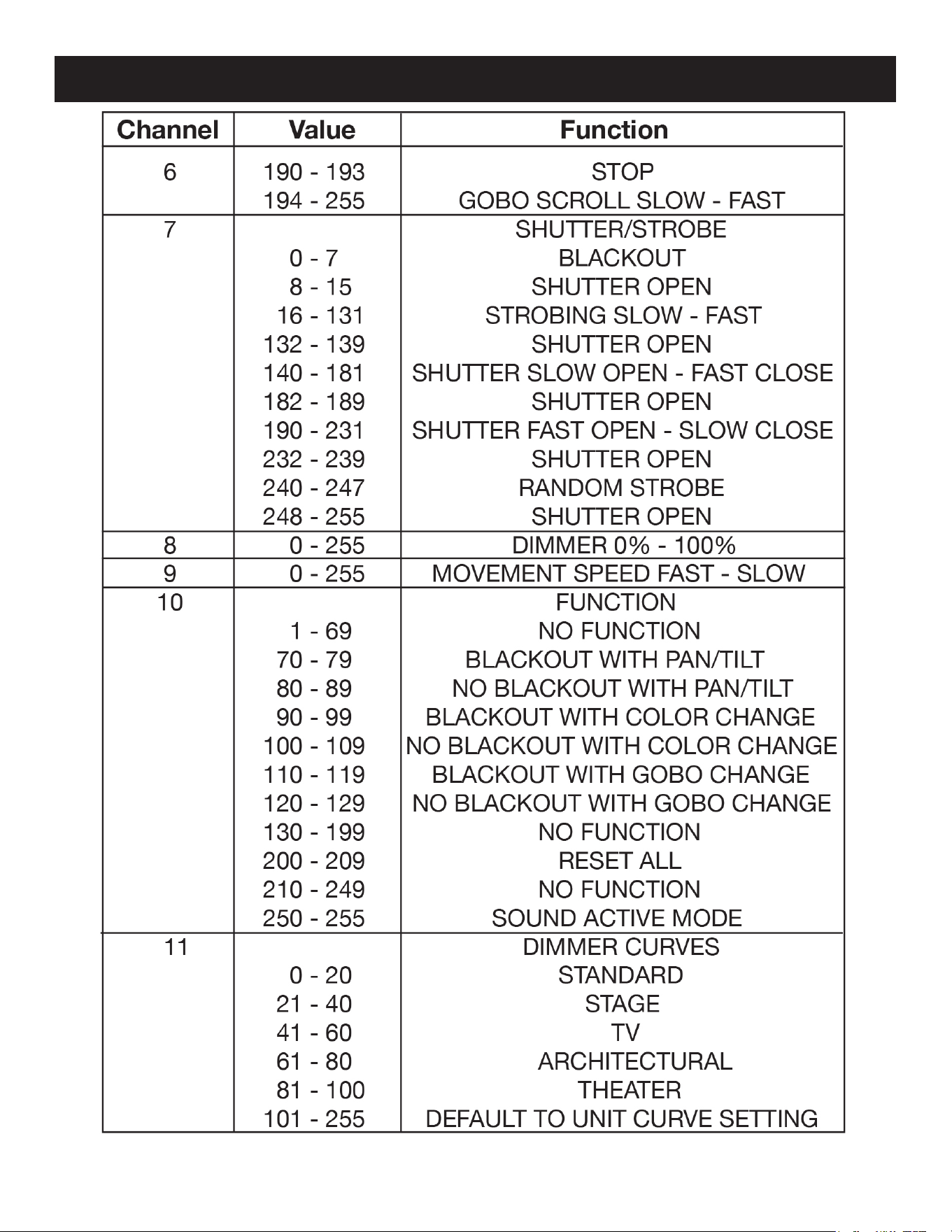
Stinger Spot 11-Channel Mode
ADJ Products, LLC - www.adj.com - Stinger Spot User Manual Page 20
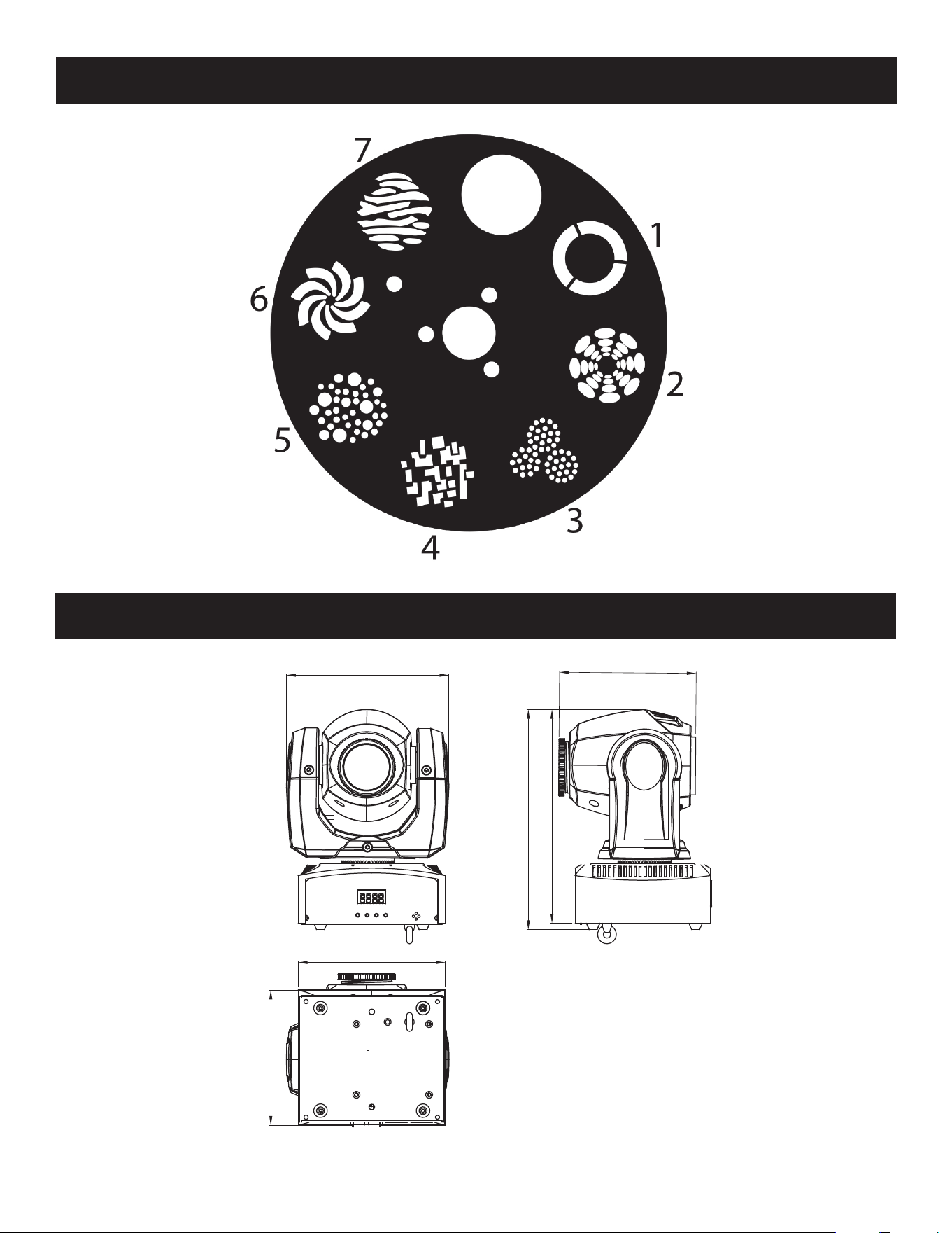
Stinger Spot Gobo Wheel
Stinger Spot CAD Drawing
173mm/6.81”
147mm/5.78”
158mm/6.22”
145mm/5.7”
236mm/9.29”
229mm/9”
ADJ Products, LLC - www.adj.com - Stinger Spot User Manual Page 21
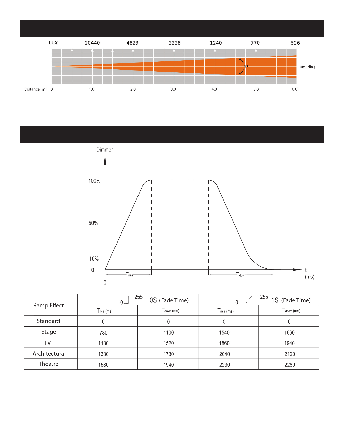
Stinger Spot Photometric Chart
Stinger Spot Dimmer Curve Chart
ADJ Products, LLC - www.adj.com - Stinger Spot User Manual Page 22

Stinger Spot Fuse Replacement
Locate and remove the unit’s power cord. Once the cord has been removed, locate the fuse holder
inside the power socket. Insert a at-head screw driver into the power socket and gently pry out the
fuse holder. Remove the bad fuse and replace with a new one. The fuse holder has a built-in socket
for a spare fuse; be sure not to confuse the spare fuse with the active fuse.
Stinger Spot Cleaning
Due to fog residue, smoke, and dust, cleaning of the internal and external optical lenses and mirror
should be carried out periodically to optimize light output. Cleaning frequency depends on the en-
vironment in which the xture operates (i.e. smoke, fog residue, dust, or dew). In heavy club use, it
is recommended to clean the xture on a monthly basis. Periodic cleaning will ensure longevity and
crisp output.
1. Use normal glass cleaner and a soft cloth to wipe down the outside casing.
2. Use a brush to wipe down the cooling vents and fan grill.
3. Clean the external optics with glass cleaner and a soft cloth every 20 days.
4. Clean the internal optics with glass cleaner and a soft cloth every 30-60 days,
5. Always be sure to dry all parts completely before plugging the unit back in.
Stinger Spot Trouble Shooting
Trouble Shooting: Listed below are a few common problems that you may encounter, with solu-
tions.
No light output from the unit;
1. Be sure the external fuse has not blown. The fuse is located on the rear panel of the unit.
2. Be sure the fuse holder is completely and properly seated.
Unit does not respond to sound;
1. Low frequencies (bass) should cause the unit to react to sound. Tapping on the microphone,
quiet or high pitched sounds may not activate the unit.
ADJ Products, LLC - www.adj.com - Stinger Spot User Manual Page 23

Stinger Spot Warranty
ADJ Products, LLC - www.adj.com - Stinger Spot User Manual Page 24
MANUFACTURER’S LIMITED WARRANTY
A. ADJ Products, LLC hereby warrants, to the original purchaser, ADJ Products, LLC products to be free of manufac-
turing defects in material and workmanship for a prescribed period from the date of purchase (see specic warranty
period on reverse). This warranty shall be valid only if the product is purchased within the United States of America,
including possessions and territories. It is the owner’s responsibility to establish the date and place of purchase by
acceptable evidence, at the time service is sought.
B. For warranty service you must obtain a Return Authorization number (RA#) before sending back the product–please
contact ADJ Products, LLC Service Department at 800-322-6337. Send the product only to the ADJ Products, LLC
factory. All shipping charges must be pre-paid. If the requested repairs or service (including parts replacement) are
within the terms of this warranty, ADJ Products, LLC will pay return shipping charges only to a designated point
within the United States. If the entire instrument is sent, it must be shipped in its original package. No accessories
should be shipped with the product. If any accessories are shipped with the product, ADJ Products, LLC shall have
no liability whatsoever for loss of or damage to any such accessories, nor for the safe return thereof.
C. This warranty is void if the serial number has been altered or removed; if the product is modied in any manner which
ADJ Products, LLC concludes, after inspection, aects the reliability of the product; if the product has been repaired
or serviced by anyone other than the ADJ Products, LLC factory unless prior written authorization was issued to pur-
chaser by ADJ Products, LLC; if the product is damaged because not properly maintained as set forth in the instruc-
tion manual.
D. This is not a service contract, and this warranty does not include maintnance, cleaning or periodic check up. During
the period specied above, ADJ Products, LLC will replace defective parts at its expense with new or refurbished
parts, and will absorb all expenses for warranty service and repair labor by reason of defects in material or workman-
ship. The sole responsibility of ADJ Products, LLC under this warranty shall be limited to the repair of the product,
or replacement thereof, including parts, at the sole discretion of ADJ Products, LLC. All products covered by this
warranty were manufactured after August 15, 2012, and bear indentifying marks to that eect.
E. ADJ Products, LLC reserves the right to make changes in design and/or improvements upon its products without
any obligation to include these changes in any products theretofore manufactured.
No warranty, whether expressed or implied, is given or made with respect to any accessory supplied with products
described above. Except to the extent prohibited by applicable law, all implied warranties made by ADJ Products, LLC
in connection with this product, including warranties of merchantability or tness, are limited in duration to the warranty
period set forth above. And no warranties, whether expressed or implied, including warranties of merchantability or t-
ness, shall apply to this product after said period has expired. The consumer’s and/or Dealer’s sole remedy shall be such
repair or replacement as is expressly provided above; and under no circumstances shall ADJ Products, LLC be liable for
any loss or damage, direct or consequential, arising out of the use of, or inability to use, this product.
This warranty is the only written warranty applicable to ADJ Products, LLC Products and supersedes all prior warranties
and written descriptions of warranty terms and conditions heretofore published.
MANUFACTURER’S LIMITED WARRANTY PERIODS
Non L.E.D. Lighting Products = 1-year (365 days) Limited Warranty (Such as: Special Eect Lighting, Intelligent Light-
ing, UV lighting, Strobes, Fog Machines, Bubble Machines, Mirror Balls, Par Cans, Trussing, Lighting Stands etc. exclud-
ing LED and lamps)
Laser Products = 1 Year (365 Days) Limited Warranty (excluding laser diodes which have a 6 month limited warranty)
L.E.D. Products = 2-year (730 days) Limited Warranty (excluding batteries which have a 180 day limited warranty).
Note: 2 Year Warranty only applies to purchases within the United States.
StarTec Series = 1 Year Limited Warranty (excluding batteries which have a 180 day limited warranty).
ADJ DMX Controllers = 2 Year (730 Days) Limited Warranty

Stinger Spot Specifications
Model: Stinger Spot
Voltage: 100 - 240V, 50/60 Hz
LED: 1 x 10W White LED
Power Consumption: 36W
Dimensions: 6.75” (L) x 5.75” (W) x 10.75” (H)
174mm x 145mm x 273mm
Weight: 7 Lbs. / 3 kgs.
Beam Angle: 13 Degrees
Fuse: 2 Amp
Duty Cycle: None
DMX: 2 DMX Channel Modes: 9-ch mode & 11-ch mode
Colors: 7 + White
Gobos: 7 + Spot
Sound Active: Yes
Working Position: Any Safe, Secure Position
Warranty: 1 Year (365 days)
Please Note: Specications and improvements in the design of this unit and this man-
ual are subject to change without any prior written notice.
Auto Sensing Voltage: This xture contains an automatic voltage switch, which will
automatically sense the voltage when it is plugged into a power source.
ADJ Products, LLC
6122 S. Eastern Ave. Los Angeles, CA, 90040 USA
Tel: 323-582-2650 / Fax: 323-725-6100
Web: www.adj.com / E-mail: [email protected]
A.D.J. Supply Europe B.V.
Junostraat 2
6468 EW Kerkrade
The Netherlands
service@adjgroup.eu / www.adj.eu
Tel: +31 45 546 85 00 / Fax: +31 45 546 85 99
ADJ Products, LLC - www.adj.com - Stinger Spot User Manual Page 25